Embed Size (px)
Citation preview

Composite Structures xxx (2010) xxx–xxx
ARTICLE IN PRESS
Contents lists available at ScienceDirect
Composite Structures
journal homepage: www.elsevier .com/locate /compstruct
Fabrication and crushing behavior of low density carbon fiber compositepyramidal truss structures
Jian Xiong a, Li Ma a, Linzhi Wu a,*, Bing Wang a, Ashkan Vaziri b
a Center for Composite Materials and Structures, Harbin Institute of Technology, Harbin 150001, PR Chinab Department of Mechanical and Industrial Engineering, Northeastern University, Boston, MA 02115, USA
a r t i c l e i n f o
Article history:Available online xxxx
Keywords:Sandwich panelMechanical propertiesPyramidal trussCarbon fiber
0263-8223/$ - see front matter Crown Copyright � 2doi:10.1016/j.compstruct.2010.03.010
* Corresponding author. Tel.: +86 451 86412549; faE-mail addresses: [email protected] (J. Xion
Please cite this article in press as: Xiong J et al. Fpos Struct (2010), doi:10.1016/j.compstruct.201
a b s t r a c t
A new method for fabricating carbon fiber composite pyramidal truss cores was developed based on themolding hot-press technique. In this method, all the continuous fibers of composite are aligned in thedirection of struts and thus, the truss structure can fully exploit the intrinsic strength of the fiber rein-forced composite. The microstructure and organizations of fibers of fabricated composite structures wereexamined using scanning electron microscope. The crushing response of the truss cores was also inves-tigated and the corresponding failure modes were studied and complemented with an analytic model ofthe core crushing response. Our results show that the fabricated low-density truss cores have superiorcompressive strength and thus, could be used in development of novel lightweight multifunctionalstructures.
Crown Copyright � 2010 Published by Elsevier Ltd. All rights reserved.
1. Introduction
Unique properties and multifunctional advantages of cellularstructures with lattice truss topologies have increased their usagein variety of engineering applications that range from blast resis-tant sandwich panels [1–9] to shape morphing [10,11] and activecooling [12,13]. The application of these cellular structures havefurther accentuated by emergence of novel manufacturing tech-niques that allow fabricating truss cores from a variety of engineer-ing materials, including composites and metallic alloys [14–22].From the structural perspective, cellular materials with latticetruss topologies are competitive to closed cell structures such ashoneycombs and are generally superior to stochastic foams [18].
In this context, fiber reinforced composite cellular structureswith lattice truss topologies have shown recently to fulfill theapparent gap between the existing materials and the unattainablematerials limit in the low-density region of the Ashby’s chart[23–26] – see Fig. 1. An example is the pioneering work ofFinnegan et al. [24], where composite pyramidal truss cores weremanufactured by using water-jet cutting process in combinationwith the snap-fitted method. In this study, only half of the fibersare aligned in the direction of truss struts and thus, the intrinsicstrength of the fiber reinforced composite is not fully exploitedby the truss structure. Here, we introduce a novel and practicalmethodology to fabricate composite pyramidal truss cores withunidirectional carbon/epoxy prepreg by the molding hot-press
010 Published by Elsevier Ltd. All r
x: +86 451 86402386.g), [email protected] (L. Wu).
abrication and crushing behav0.03.010
method. In this method, all the continuous fibers of compositeare aligned in the direction of fabricated truss structures. Thedetails related to fabrication of the truss cores are presented inSection 2. In Section 3, we examined the microstructure of thecreated composite structures using scanning electron microscope(SEM). Furthermore, we have studied the crushing behavior ofthe composite truss cores with different core relative density. Ascan be seen in Fig. 1, the fabricated truss cores occupy the low-density region of the chart and their strength is very close thetheoretical strength limit of the lattice trusses.
2. Fabrication method
Fig. 2 shows the schematic of the manufacturing method ofcomposite pyramidal lattice cores. The mold consists of four differ-ent parts: (1) up web frames, (2) down web frames, (3) blocks and(4) the base tooling – which were made of chrome steel. Theexpansion blocks used in the process are cast silicon rubber andwere laid into the space between the base tooling and down webframes. The parts were assembled as shown in Fig. 2a prior toinserting the composite slender laps into the strut compactionareas. For manufacturing the carbon fiber composite pyramidaltruss cores, we used unidirectional carbon fiber/epoxy prepregsheets with thickness r = 0.15 mm (T700/epoxy composite, BeijingInstitute of Aeronautical Materials, China). The properties of a uni-directional prepreg are listed in Table 1.
The slender unidirectional fiber reinforced laps were cut fromthe prepreg sheets using scissor. Then, the laps were put into thestrut compaction at 0� play angle to build the composite pyramidal
ights reserved.
ior of low density carbon fiber composite pyramidal truss structures. Com-

Fig. 1. Modified Ashby’s strength–density chart for a wide range of engineering materials [23]. The maximum theoretical strength of composite pyramidal truss cores isshown by the solid line marked ‘analytical’, we have added to this chart, the measured properties of composite pyramidal truss cores investigated here located in the lowdensity – high strength region of the chart.
Fig. 2. (a) Schematic of the manufacturing mold. (b) The side view of the mold.
Table 1Properties of unidirectional lamella (T700/epoxy composites).
Properties Value
0� Tensile strength (MPa) 14000� Tensile modulus (GPa) 12390� Tensile strength (MPa) 1890� Tensile modulus (GPa) 8.30� Compression strength (MPa) 8500� Compression modulus (GPa) 10090� Compression strength (MPa) 9690� Compression modulus (GPa) 8.4In-plane shear strength (MPa) 16.0In-plane shear modulus (GPa) 4.8Interlayer shear strength (MPa) 60Poisson’s ratio 0.3Volume fraction of fibers 57% ± 3Density (kg/m3) 1550
2 J. Xiong et al. / Composite Structures xxx (2010) xxx–xxx
ARTICLE IN PRESS
truss structures. Thus, in each strut of the fabricated truss core, thefibers are aligned in the direction of truss struts. Prior to processing,a release agent was brushed on the mold surfaces to allow easy sep-aration of the structures from the mold after curing. The compositewas cured in a hot-press at constant pressure 0.5 MPa and temper-ature 130 �C for 1.5 h. The composite pyramidal lattice cores weredetached from the mold after the solidification of the resin.
Fig. 3a shows an example of the created composite pyramidallattice structure with relative core density 1.81%. The density ofthe truss core is given by
q ¼ ð2b cos xþ h� 2tÞdt
ðhþ 2bÞ2 cos3 xhqs ð1Þ
where the geometrical parameters, b, h, d and x are shown in theschematic figure of the unit cell of the truss structure shown in
Please cite this article in press as: Xiong J et al. Fabrication and crushing behavior of low density carbon fiber composite pyramidal truss structures. Com-pos Struct (2010), doi:10.1016/j.compstruct.2010.03.010

Fig. 4. The scanning electron microscopy picture of struts with �q ¼ 1:81%. (a) Schematic image of the unit cell of pyramidal truss structures. (b) The transverse cross sectionA–A of struts. (c) The junction between two plies (B–B). (d) The triangular region between the edges of two slender plies in the junction (C–C).
Fig. 3. (a) Fabricated carbon fiber composite pyramidal truss structures with �q ¼ 1:81%. (b) Sketch of the unit cell of the pyramidal core. (c) Sandwich panel with carbon fibercomposite pyramidal truss core (�q ¼ 3:70%).
J. Xiong et al. / Composite Structures xxx (2010) xxx–xxx 3
ARTICLE IN PRESS
Fig. 3b. The pyramidal truss structure shown in Fig. 3a hasb = 4 mm, h = 15 mm, d = 3 mm, x = 45� and each strut of the
Please cite this article in press as: Xiong J et al. Fabrication and crushing behavpos Struct (2010), doi:10.1016/j.compstruct.2010.03.010
pyramidal truss is made of six slender laps. Fig. 3c shows a sand-wich structure, where the fabricated composite truss structure were
ior of low density carbon fiber composite pyramidal truss structures. Com-

Fig. 5. Two typical struts were investigated in the study. Strut 1 was intended to obtain the fracture failure strength of struts with the relative density 1.81%. Strut 2 wasintended to obtain the delamination strength of the struts with the relative density 4.70%.
4 J. Xiong et al. / Composite Structures xxx (2010) xxx–xxx
ARTICLE IN PRESS
employed as the core material. These sandwich structures were fab-ricated by attaching the pyramidal truss structures to flat carbonfiber reinforced face sheets with adhesive (08-57, HeilongjiangInstitute of Petrochemical).
3. Microstructure of the fabricated truss structures
In Fig. 4, we show the SEM images acquired from three differentcross sections of the truss structures (cross sections A–A, B–B andC–C shown in Fig. 4a). The SEM images of the strut cross sectionsshow that the distribution of carbon fibers is approximately uni-form in the strut cross section in Fig. 4b. Fig. 4c and d shows theSEM images acquired from two different planes at the junctionsof the struts. Fig. 4c shows that the composite fibers are continuousin two normal directions (fiber directions are shown in each direc-tion with a yellow dot and arrow1) and also show the proper bond-ing of the composite resin and fibers in the junction of the twoperpendicular struts. In contrast, Fig. 4d shows a ‘triangular region’of approximately 1.2 mm in length with almost no fiber. Voids aslong as 300 lm, which is much larger than the typical void size ob-served in the microstructure of struts are observed in this region.The direction of the fibers along the edge of this triangular regionis parallel to the triangle sides, as shown in Fig. 4d. Because in thecurrent design, all the slender plies are continuous through thestruts cross junction, the material at the cross junction is effec-tively twice of the material of each strut, the induced pressure inthis region during forming and curing of the specimens is not uni-form and generally lower than the pressure applied to the struts.This non-uniform pressure results in remarkable amount of voidsin the triangle region, which is one of the weak areas of the trussstructure.
4. Stiffness and fracture strength of composite struts
Prior to testing the mechanical behavior of pyramidal trusscores, we investigated the stiffness and strength of compositestruts under uniaxial compression. The results of this study will
1 For interpretation of color in Fig. 4, the reader is referred to the web version ofthis article.
Please cite this article in press as: Xiong J et al. Fabrication and crushing behavpos Struct (2010), doi:10.1016/j.compstruct.2010.03.010
be used in Sections 5 and 6 to interpret the response and fractureof composite truss structures under crushing. The struts were de-tached from two typical relative densities pyramidal truss cores.The applied load was measured via the load cell of the test machinewhile a laser extensometer was used to measure the nominal axialstrain in the specimens. A nominal applied strain rate of 10�3 s�1
was employed in these tests using INSTRON (5569).Column compression tests were conducted in which the speci-
mens were compressed between two flat and parallel platens withno end-clamping of the struts. The tests were conducted on rectan-gular specimens that were extracted from the manufactured pyra-midal truss cores as sketched in Fig. 5. These struts are sufficientlythick in both directions to prevent Euler buckling of the specimens.Prior to testing, the ends of struts with thickness 0.9 mm (strut 1)were reinforced by resin and fixture to prevent delamination. Sincethe struts in a truss sandwich panel are considered to be pinned atboth ends, tests are considered to be valid only when there is nomovement on the fixture platen for either end of the sample. In or-der to satisfy this boundary condition, it is important to make thetop and bottom surfaces parallel. However, there are several otherfactors that could not be controlled in the testing process, such asstruts deviation from the centerline of the fixture and struts slip-ping. Due to these factors, only 12 valid test data were obtainedfor each struts configuration, even though more than 40 compres-sion tests were carried out on individual struts extracted from thesandwich panels for each relative density.
Fig. 6 shows an example of measured nominal stress–straincurves of struts 1 and 2: the struts display a linear elastic responsefollowed by struts fracture, see Fig. 6b, left image. We used themeasured data to estimate the elastic modulus and failure strengthof the strut composites. For strut 1, the average unloading elasticmodulus was estimated as Es = 20.5 GPa and the fracture failurestrength rcf = 493.761 MPa. For strut 2, the average unloading elas-tic modulus was measured as Es = 21.8 GPa and the delaminationfailure strength rcd = 298.246 MPa.
5. Crushing response of pyramidal cores
We carried out uniaxial compression test using a screw-driventesting machine (INSTRON 5569) following ASTM C365/C 364M-05
ior of low density carbon fiber composite pyramidal truss structures. Com-

Fig. 6. (a) The measured compressive stress versus strain response of the materials used to manufacture cores with the two typical struts. (b) Photographs of the two typicalstruts after fracture and delamination.
J. Xiong et al. / Composite Structures xxx (2010) xxx–xxx 5
ARTICLE IN PRESS
[27]. Pyramidal truss cores were manufactured using the techniqueoutlined in Section 2 with b = 4 mm, h = 15 mm, d = 3 mm, x = 45�and three relative densities, �q ¼ 1:25% (with four plies throughthickness), 1.81% (with six plies through thickness) and 4.70%(with 20 plies through thickness). The compression tests were car-ried out in the quasi-static regime with a nominal displacementrate of 0.5 mm/min. Unloading–reloading curves were obtainedand used to determine the apparent material properties of thetruss cores. At least three tests were conducted for each coredensity.
The compressive stress–strain response of three pyramidaltruss sandwich panels is shown in Fig. 7. The initial linear re-sponse of the structures is followed by a nonlinear regime dueto the progressive failure of struts or debonding. After reachinga peak stress, the stress decreases with further crushing and aseries of local failure events leads to a reduction in the overallstrength of the core. We derived an analytical expression for
Please cite this article in press as: Xiong J et al. Fabrication and crushing behavpos Struct (2010), doi:10.1016/j.compstruct.2010.03.010
the ‘‘effective” compressive elastic modulus of the compositepyramidal cores, by analyzing the elastic deformation of a singlestrut of a pyramidal truss core. The analytical model of trussstructure deformation attached to two rigid flat plates is shownin Fig. 8. Symmetry considerations for individual struts dictatethat their top end can only move along the z-direction. For an im-posed displacement d in the z-direction, the axial force, FA, andshear force, FS, in a strut are given by the elementary beams the-ory as
FA ¼Esdt sin2 xðh� 2tÞ d; FS ¼
12EsI cos x sin3 xðh� 2tÞ3
d ð2Þ
where Es denotes the apparent elastic modulus of individual strutsand I = dt3/12. The total resisting force of truss structure againstcrushing, F can be obtained using the energy method. AssumingDx � 0 gives
ior of low density carbon fiber composite pyramidal truss structures. Com-
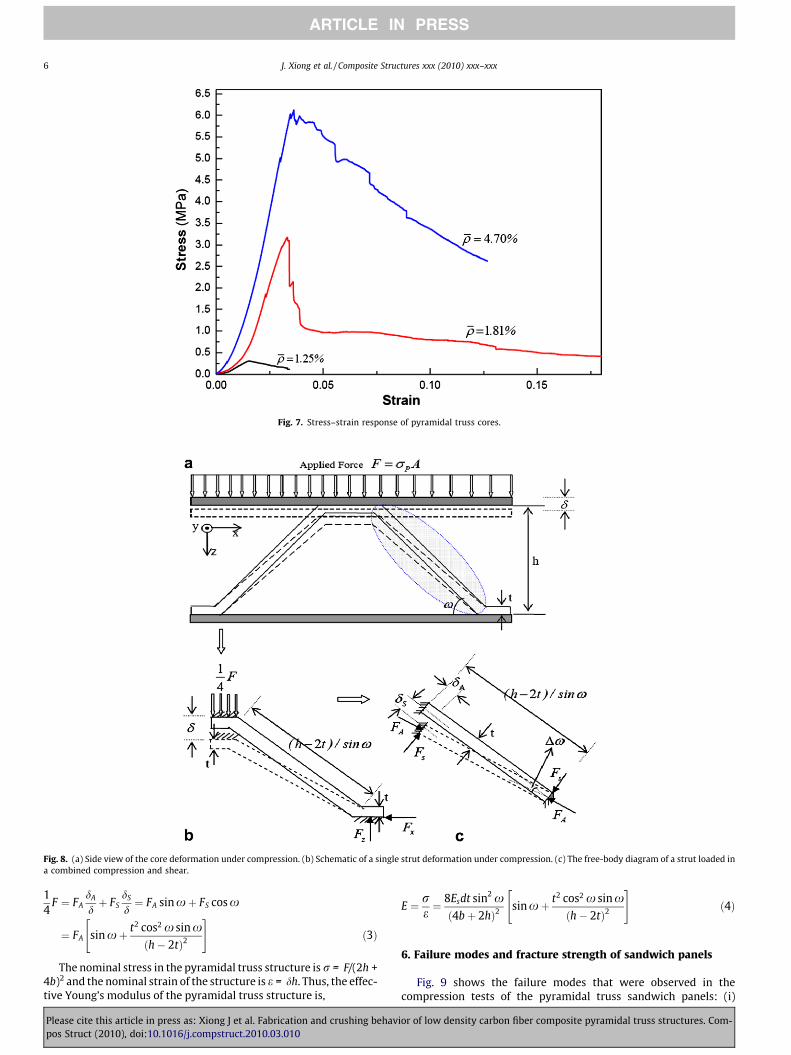
Fig. 7. Stress–strain response of pyramidal truss cores.
Fig. 8. (a) Side view of the core deformation under compression. (b) Schematic of a single strut deformation under compression. (c) The free-body diagram of a strut loaded ina combined compression and shear.
6 J. Xiong et al. / Composite Structures xxx (2010) xxx–xxx
ARTICLE IN PRESS
14
F ¼ FAdA
dþ FS
dS
d¼ FA sinxþ FS cos x
¼ FA sin xþ t2 cos2 x sin xðh� 2tÞ2
" #ð3Þ
The nominal stress in the pyramidal truss structure is r = F/(2h +4b)2 and the nominal strain of the structure is e = dh. Thus, the effec-tive Young’s modulus of the pyramidal truss structure is,
Please cite this article in press as: Xiong J et al. Fabrication and crushing behavpos Struct (2010), doi:10.1016/j.compstruct.2010.03.010
E ¼ re¼ 8Esdt sin2 xð4bþ 2hÞ2
sinxþ t2 cos2 x sinxðh� 2tÞ2
" #ð4Þ
6. Failure modes and fracture strength of sandwich panels
Fig. 9 shows the failure modes that were observed in thecompression tests of the pyramidal truss sandwich panels: (i)
ior of low density carbon fiber composite pyramidal truss structures. Com-

Fig. 9. Compressive failure modes for the composite pyramidal cores.
Table 2Experimental results and comparison with analytical predictions.
Specimengeometry
t(mm)
Obs. fail.mode
Analyt.fail. mode
Obs. fail. Analyt./obs.Stiffness/strength(MPa)
Stiffness/strength(MPa)
1 0.6 E E 45.8/0.304 49.3/0.3072 0.9 F F 70.3/3.17 74.0/3.563 3.0 D D 241.5/6.18 262.2/7.17
E = Euler buckling mode; F = fracture mode; D = delamination mode.Analyt. = analytical; Obs. = observed.
J. Xiong et al. / Composite Structures xxx (2010) xxx–xxx 7
ARTICLE IN PRESS
Euler buckling of struts, (ii) strut fracture, (iii) delamination, and(iv) debonding. The debonding is governed by the adhesivestrength and adhesive behavior and are not further exploredhere. In this part, we discuss the other three failure mechanismsof the sandwich panels which relate directly to the geometry ofpyramidal truss structure and the composite mechanicalbehavior.
6.1. Euler buckling of the struts
The peak stress for a pyramidal core with �q ¼ 1:25% occurs at0.304 MPa before any visible failure and is followed by Euler buck-ling and the subsequent large bending deformation of struts – seeFig. 9a. The Euler buckling load of an end-clamped strut subjectedto axial load can be estimated from
FE ¼4p2EsI sin2 xðh� 2tÞ2
ð5Þ
Thus, the nominal compressive collapse strength of a pyramidalcore due to the elastic buckling of its constituent struts can be esti-mated from
rE ¼32p2EsI sin2 x
ð4bþ 2hÞ2ðh� 2tÞ2sinxþ t2 cos2 x sinx
ðh� 2tÞ2
" #ð6Þ
6.2. Fracture of the struts
For a pyramidal core with �q ¼ 1:81%, the strut fracture is thedominant mode of failure. An upper limit for the failure load ofthe composite struts is FA ¼ rcf dt, where rcf is the strut’s fracturestress failure. The theoretical applied stress associated with the on-set of strut fracture, rF can be calculated from
rF ¼8rcf dt
ð4bþ 2hÞ2sin xþ t2 cos2 x sin x
ðh� 2tÞ2
" #ð7Þ
Please cite this article in press as: Xiong J et al. Fabrication and crushing behavpos Struct (2010), doi:10.1016/j.compstruct.2010.03.010
6.3. Delamination failure of the struts
For a pyramidal truss core with �q ¼ 4:70%, delamination anddebonding of the struts is the dominant mode of failure. In general,it was observed that the delamination initiates in the triangle re-gion located at the junction of struts and then propagates alongthe plies as the sandwich panel was crushed further. The stressassociated with the onset of delamination can be calculated from,
rD ¼8rcddt
ð4bþ 2hÞ2sinxþ t2 cos2 x sinx
ðh� 2tÞ2
" #ð8Þ
where rcd is the strut’s delamination stress failure.
7. Conclusions
We conclude by giving detailed experimental results and theo-retical predictions for three representative pyramidal truss cores –one failing by struts Euler buckling, one by struts fracture and oneby struts delamination. The experimental results for each failuremode are summarized in Table 2 and compared with the analyt-ical prediction. Good agreement is observed between the mea-surements and predictions for the Euler buckling mode, as wellas the fracture and delamination failure modes. The measuredstrength (peak stress) for these specimens is somewhat lowerthan the theoretical strengths, due to imperfections and voids inthe struts. Specifically, the measured stress of the specimen with�q ¼ 4:70% is much lower than the predicted one. The large loadapplied to this core results in debonding between the core andface sheets. It should be noted with increasing the core relativedensity, the struts intend to fail by delamination, not by fracture,as the triangle region becomes larger by increasing the strut’sthickness.
The molding hot-press method proposed here for fabricatingcomposite pyramidal truss structures is an effective method formanufacturing lightweight carbon fiber truss cores. A key limita-tion of the proposed is that in the current design, the pyramidalcores have considerable amount of avoids at the strut’s junctions.Possible improvements in the proposed method includes: (a) opti-mizing the design of the mold and the molding condition (pressureand temperature) and (b) preventing bubbles in the struts forma-tion, especially at the plies junction. As illustrated in Fig. 1, the fab-ricated composite structures have strength close to the theoreticalstrength of the pyramidal trusses and thus, can be used in develop-ment of novel lightweight multifunctional structures.
Acknowledgements
This work was supported by the National Science Foundation ofChina under Grant Nos. 90816024 and 10872059, the Major StateBasic Research Development Program of China (973 Program) un-der Grant No. 2006CB601206, the Program of Excellent Team inHarbin Institute of Technology and the Department of Mechanicaland Industrial Engineering at Northeastern University (AV). L.M.
ior of low density carbon fiber composite pyramidal truss structures. Com-
8 J. Xiong et al. / Composite Structures xxx (2010) xxx–xxx
ARTICLE IN PRESS
acknowledges the Program for New Century Excellent Talents inUniversity under Grant No. NCET-08-0152.
References
[1] Kim TD. Fabrication and testing of thin composite isogrid stiffened panel.Compos Struct 2000;49(1):21–5.
[2] Wallach JC, Gibson LJ. Mechanical behavior of a three-dimensional trussmaterial. Int J Solids Struct 2001;38(40–41):7181–96.
[3] Evans AG, Huchinson JW, Fleck NA, Ashby MF, Wandley HNG. The topologicaldesign of multifunctional cellular metals. Progr Mater Sci 2001;46(3–4):309–27.
[4] Deshpande VS, Fleck NA. Collapse of truss core sandwich beams in 3-pointbending. Int J Solids Struct 2001;38(36–37):6275–305.
[5] Cote F, Deshpande VS, Fleck NA. Shear fatigue strength of a prismatic diamondsandwich core. Scr Mater 2007;56(7):585–8.
[6] Yungwirth CJ, Radford Darren D, Aronson Mark, Wadley HNG. Experimentassessment of the ballistic response of composite pyramidal lattice trussstructures. Compos Part B: Eng 2008;39(3):556–9.
[7] Vaziri A, Xue Z. Mechanical behavior and constitutive modeling of metal cores.J Mech Mater Struct 2007;2(9):1743–61.
[8] Mori L, Lee S, Xue Z, Vaziri A, Queheillalt D, Wadley HNG, et al. On the behaviorof sandwich structures subjected to under water impulsive loads. J Mech MaterStruct 2007;2(10):1981–2006.
[9] Gibson LJ, Ashby MF. Cellular solids: structure and properties. CambridgeUniversity Press; 1997.
[10] Donev Aleksandar, Torquato Salvatore. Energy-efficient actuation in infinitelattice structures. J Mech Phys Solids 2003;51(8):1459–75.
[11] Hutchinson RG, Wicks N, Evans AG, Fleck NA, Hutchinson JW. Kagome platestructures for actuation. Int J Solids Struct 2003;40(25):6969–80.
[12] Gu S, Lu TJ, Evans AG. On the design of two-dimensional cellular metals forcombined heat dissipation and structural load capacity. Int J Heat Mass Trans2001;44(11):2163–75.
[13] Tian J, Kim T, Lu TJ, Hodson HP, Queheillalt DT, Sypeck DJ, et al. The effects oftopology upon fluid-flow and heat-transfer within cellular copper structures.Int J Heat Mass Trans 2004;47(14–16):3171–86.
Please cite this article in press as: Xiong J et al. Fabrication and crushing behavpos Struct (2010), doi:10.1016/j.compstruct.2010.03.010
[14] Zupan M, Deshpande VS, Fleck NA. The out-of-plane compressive behaviour ofwoven-core sandwich plates. Eur J Mech A/Solids 2004;23(3):411–21.
[15] Rathbun HJ, Zok FW, Waltner SA, Mercer C, Evans AG, Queheillalt DT, WadleyHNG. Structural performance of metallic sandwich beams with hollow trusscores. Acta Mater 2006;54(20):5509–18.
[16] Queheillalt DT, Wadley HNG. Pyramidal lattice truss structures with hollowtrusses. Mater Sci Eng A 2005;397:132–7.
[17] Cote F, Deshpande VS, Fleck NA, Evans AG. The compressive and shearresponses of corrugated and diamond lattice materials. Int J Solids Struct2006;43(20):6220–42.
[18] Queheillalt DT, Murty Yellapu, Wadley HNG. Mechanical properties of anextruded pyramidal lattice truss sandwich structure. Scr Mater 2008;58(1):76–9.
[19] Moongkhamklang Pimsiree, Elzey Dana M, Wadley HNG. Titanium matrixcomposite lattice structures. Composites: Part A 2008;39(2):176–87.
[20] Queheillalt DT, Wadley HNG. Titanium alloy lattice truss structures. Mater Des2009;30:1966–75.
[21] Fan HL, Meng FH, Yang W. Sandwich panels with Kagome lattice coresreinforced by carbon fibers. Compos Struct 2007;81(4):533–9.
[22] Kevin O’Brien T, Paris Isabelle L. Exploratory investigation of failuremechanisms in transition regions between solid laminates and X-cor trusssandwich. Compos Struct 2002;57(4):189–204.
[23] Ashby MF, Brechet YJM. Designing hybrid materials. Acta Mater2003;51(19):5801–21.
[24] Finnegan K, Kooistra G, Wadley Haydn NG, Deshpande VS. The compressiveresponse of carbon fiber composite pyramidal truss sandwich cores. Int JMater Res 2007;98:1264–72.
[25] Russell BP, Deshpande VS, Wadley HNG. Quasistatic deformation and failuremodes of composite square honeycombs. J Mech Mater Struct 2008;3(7):1315–40.
[26] Lee Byung-Kon, Kang Ki-Ju. Compressive strength of tube-woven Kagome trusscores. Scr Mater 2009;60(6):391–4.
[27] ASTM: C365/C 364M-05. Standard test method for flat wise compressiveproperties of sandwich cores. West Conshohocken (PA): ASTM Int.;2006.
ior of low density carbon fiber composite pyramidal truss structures. Com-