Embed Size (px)
Citation preview
ISSN(Online) : 2319-8753 ISSN (Print) : 2347-6710
International Journal of Innovative Research in Science, Engineering and Technology
(An ISO 3297: 2007 Certified Organization)
Vol. 4, Issue 7, July 2015
Copyright to IJIRSET DOI:10.15680/IJIRSET.2015.0407159 6396
Design and Analysis of Rocket Motor Bolted Joint for Enhanced Strength
P Rajamani 1, Dr G Srinivasa Gupta 2
P.G. Student, Department of Mechanical Engineering, VNR VJIET Engineering College, Hyderabad, India1
Professor, Department of Mechanical Engineering, VNR VJIET Engineering College, Hyderabad, India2
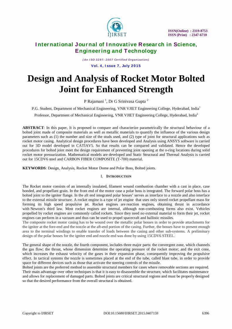
ABSTRACT: In this paper, It is proposed to compare and characterize parametrically the structural behaviour of a bolted joint made of composite materials as well as metallic materials to quantify the influence of the various design parameters such as (1) the number and size of the studs used, and (2) type of joint for structural applications such as rocket motor casing. Analytical design procedures have been developed and Analysis using ANSYS software is carried out for 3D model developed in CATIAV5. So that results can be compared and validated. Hence the developed procedures for bolted joint meet the design requirement of preventing joint opening at the o-ring locations during solid rocket motor pressurization. Mathematical models are developed and Static Structural and Thermal Analysis is carried out for 15CDV6 steel and CARBON FIBER COMPOSITE (T-700) material. KEYWORDS: Design, Analysis, Rocket Motor Dome and Polar Boss, Bolted joints.
I. INTRODUCTION
The Rocket motor consists of an internally insulated, filament wound combustion chamber with a cast in place, case bonded, and propellant grain. In the front end of the motor case a polar boss is integrated. The forward polar boss has a bolted joint to the igniter flange. In the aft end integrated polar bosses’ serves as interface to a nozzle and also interface to the external missile structure. A rocket engine is a type of jet engine that uses only stored rocket propellant mass for forming its high speed propulsive jet. Rocket engines are reaction engines, obtaining thrust in accordance with Newton's third law. Most rocket engines are internal, although non-combusting forms also exist. Vehicles propelled by rocket engines are commonly called rockets. Since they need no external material to form their jet, rocket engines can perform in a vacuum and thus can be used to propel spacecraft and ballistic missiles. The composite rocket motor casing has to be wound over the metallic polar bosses in order to provide attachments for the igniter at the fore-end and the nozzle at the aft-end portion of the casing. Further, the bosses have to present enough area to the terminal windings to enable transfer of loads between the casing and other sub-systems. A preliminary design of the polar bosses for the igniter end and nozzle end was done by using 15CDV6 STEEL. The general shape of the nozzle, the fourth component, includes three major parts: the convergent zone, which channels the gas flow; the throat, whose dimension determine the operating pressure of the rocket motor; and the exit cone, which increases the exhaust velocity of the gases in their expansion phase, consequently improving the propulsive effect. In tactical systems the nozzle is sometimes placed at the end of the tube, called blast tube, in order to provide space for different devices such as those that activate the steering controls of the missile. Bolted joints are the preferred method to assemble structural members for cases where removable sections are required. Their main advantage over other techniques is that it is easy to disassemble the structure, which facilitates maintenance and allows for replacement of damaged parts. Bolted joints are critical structural regions and must be properly designed so that the desired performance from the overall structural is obtained.
ISSN(Online) : 2319-8753 ISSN (Print) : 2347-6710
International Journal of Innovative Research in Science, Engineering and Technology
(An ISO 3297: 2007 Certified Organization)
Vol. 4, Issue 7, July 2015
Copyright to IJIRSET DOI:10.15680/IJIRSET.2015.0407159 6397
II. PROBLEM DESCRIPTION 1. Elements of Rocket Motor Bolted Joints
Rocket motor polar boss Bolted joints Rocket motor intermediate dome
The bolted joints are mainly design in Solid Rocket Motor to prevent hot gas leakage redirects internal forces around the bolts to reduce gap opening moments. A design requirement for the bolted joint is that no gap exists between the two flanges at the O-ring location during firing of Solid Rocket Motor.
III. DESIGN CALICULATIONS
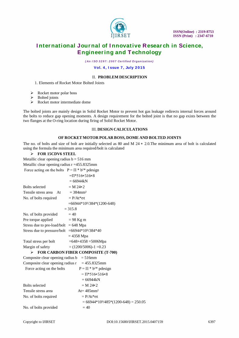
OF ROCKET MOTOR POLAR BOSS, DOME AND BOLTED JOINTS The no. of bolts and size of bolt are initially selected as 80 and M 24 2.0.The minimum area of bolt is calculated using the formula the minimum area required/bolt is calculated
FOR 15CDV6 STEEL Metallic clear opening radius b = 516 mm Metallic clear opening radius r =455.8325mm Force acting on the bolts P = Π * b²* pdesign =Π*5165168 = 66944kN Bolts selected = M 242 Tensile stress area At = 384mm² No. of bolts required = P/At*t =66944*10³/384*(1200-648) = 315.8 No. of bolts provided = 40 Pre torque applied = 98 Kg m Stress due to pre-load/bolt = 648 Mpa Stress due to pressure/bolt =66944*10³/384*40 = 4358 Mpa Total stress per bolt =648+4358 =5006Mpa Margin of safety = (1200/5006)-1 =0.23
FOR CARBON FIBER COMPOSITE (T-700) Composite clear opening radius b = 516mm Composite clear opening radius r = 455.8325mm Force acting on the bolts P = Π * b²* pdesign = Π*5165168 = 66944kN Bolts selected = M 242 Tensile stress area At= 485mm² No. of bolts required = P/At*t = 66944*10³/485*(1200-648) = 250.05 No. of bolts provided = 40
ISSN(Online) : 2319-8753 ISSN (Print) : 2347-6710
International Journal of Innovative Research in Science, Engineering and Technology
(An ISO 3297: 2007 Certified Organization)
Vol. 4, Issue 7, July 2015
Copyright to IJIRSET DOI:10.15680/IJIRSET.2015.0407159 6398
Pre torque applied = 98 Kg m Stress due to pre-load/bolt = 648 Mpa Stress due to pressure/bolt =66944*10³/384*40 = 4358 Mpa Total stress per bolt =648+4358 =5006Mpa Margin of safety = (1200/5006)-1 = 0.23
IV. MODELLING OF DOME, POLAR BOSS AND BOLTED JOINTS The geometry of rocket motor polar boss, bolted joint, rocket motor dome is created as 2D model using CATIYA V5 Software. The 2D model is converted into 2D solid surface then it is revolved around 360 about X-axis to convert into 3D solid model surface. So finally 3D model of rocket motor parts of bolted joints, dome, and polar boss are generated.
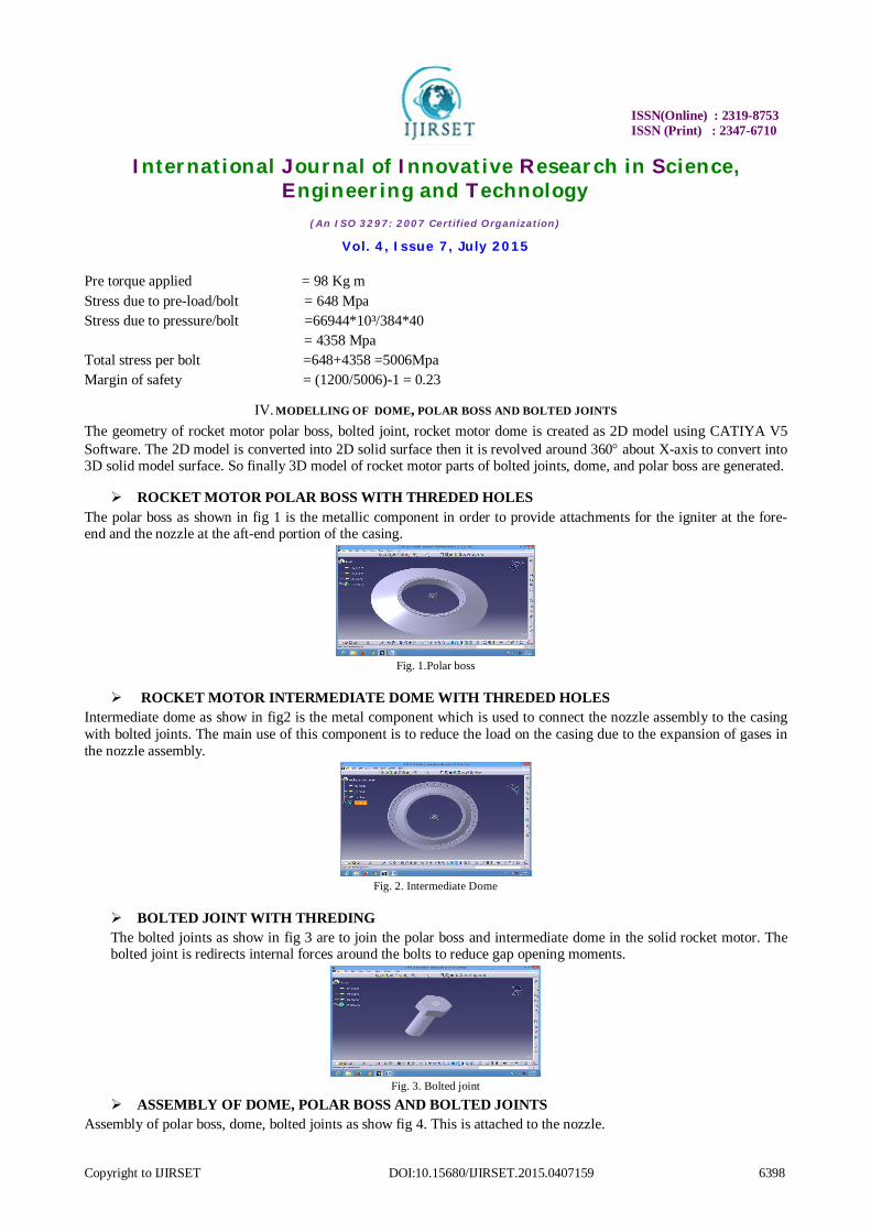
ROCKET MOTOR POLAR BOSS WITH THREDED HOLES The polar boss as shown in fig 1 is the metallic component in order to provide attachments for the igniter at the fore-end and the nozzle at the aft-end portion of the casing.
Fig. 1.Polar boss
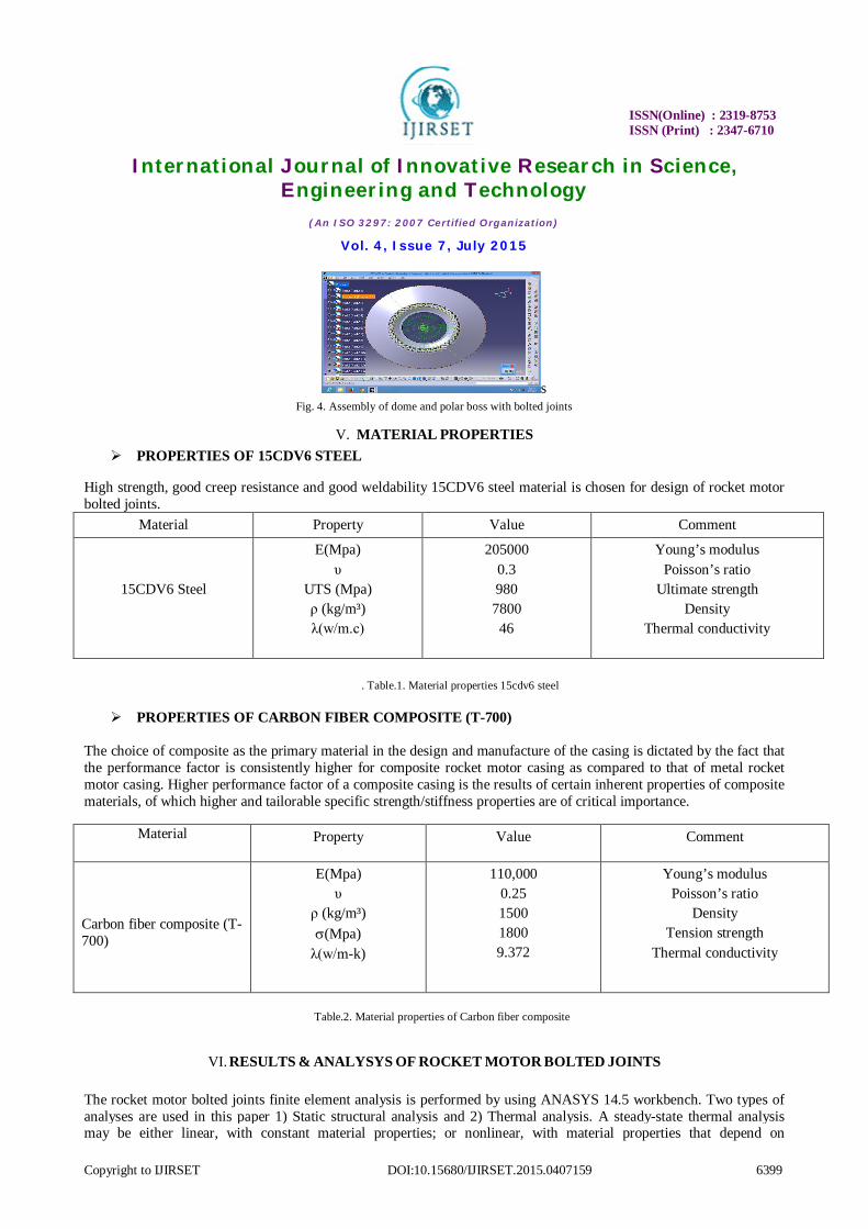
ROCKET MOTOR INTERMEDIATE DOME WITH THREDED HOLES Intermediate dome as show in fig2 is the metal component which is used to connect the nozzle assembly to the casing with bolted joints. The main use of this component is to reduce the load on the casing due to the expansion of gases in the nozzle assembly.
Fig. 2. Intermediate Dome
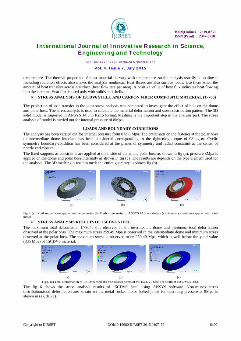
BOLTED JOINT WITH THREDING The bolted joints as show in fig 3 are to join the polar boss and intermediate dome in the solid rocket motor. The bolted joint is redirects internal forces around the bolts to reduce gap opening moments.
Fig. 3. Bolted joint
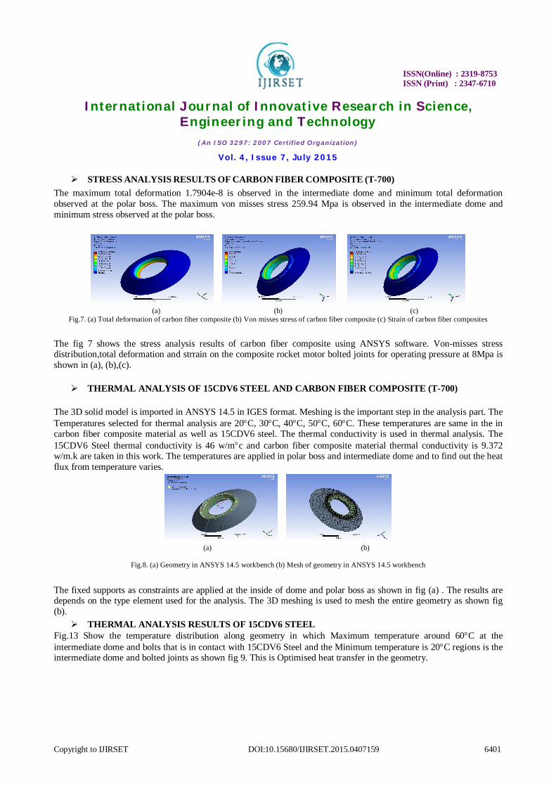
ASSEMBLY OF DOME, POLAR BOSS AND BOLTED JOINTS Assembly of polar boss, dome, bolted joints as show fig 4. This is attached to the nozzle.
ISSN(Online) : 2319-8753 ISSN (Print) : 2347-6710
International Journal of Innovative Research in Science, Engineering and Technology
(An ISO 3297: 2007 Certified Organization)
Vol. 4, Issue 7, July 2015
Copyright to IJIRSET DOI:10.15680/IJIRSET.2015.0407159 6399
s Fig. 4. Assembly of dome and polar boss with bolted joints
V. MATERIAL PROPERTIES PROPERTIES OF 15CDV6 STEEL
High strength, good creep resistance and good weldability 15CDV6 steel material is chosen for design of rocket motor bolted joints.
Material Property Value Comment
15CDV6 Steel
E(Mpa) υ
UTS (Mpa) ρ (kg/m³) λ(w/m.c)
205000 0.3 980 7800 46
Young’s modulus Poisson’s ratio
Ultimate strength Density
Thermal conductivity
. Table.1. Material properties 15cdv6 steel
PROPERTIES OF CARBON FIBER COMPOSITE (T-700)
The choice of composite as the primary material in the design and manufacture of the casing is dictated by the fact that the performance factor is consistently higher for composite rocket motor casing as compared to that of metal rocket motor casing. Higher performance factor of a composite casing is the results of certain inherent properties of composite materials, of which higher and tailorable specific strength/stiffness properties are of critical importance.
Material Property
Value
Comment
Carbon fiber composite (T-700)
E(Mpa) υ
ρ (kg/m³) (Mpa)
λ(w/m-k)
110,000 0.25 1500 1800 9.372
Young’s modulus Poisson’s ratio
Density Tension strength
Thermal conductivity
Table.2. Material properties of Carbon fiber composite
VI. RESULTS & ANALYSYS OF ROCKET MOTOR BOLTED JOINTS
The rocket motor bolted joints finite element analysis is performed by using ANASYS 14.5 workbench. Two types of analyses are used in this paper 1) Static structural analysis and 2) Thermal analysis. A steady-state thermal analysis may be either linear, with constant material properties; or nonlinear, with material properties that depend on
ISSN(Online) : 2319-8753 ISSN (Print) : 2347-6710
International Journal of Innovative Research in Science, Engineering and Technology
(An ISO 3297: 2007 Certified Organization)
Vol. 4, Issue 7, July 2015
Copyright to IJIRSET DOI:10.15680/IJIRSET.2015.0407159 6400
temperature. The thermal properties of most material do vary with temperature, so the analysis usually is nonlinear. Including radiation effects also makes the analysis nonlinear. Heat fluxes are also surface loads. Use them when the amount of heat transfers across a surface (heat flow rate per area). A positive value of heat flux indicates heat flowing into the element. Heat flux is used only with solids and shells.
STRESS ANALYSIS OF 15CDV6 STEEL AND CARBON FIBER COMPOSITE MATERIAL (T-700)
The prediction of load transfer in the joint stress analysis was contacted to investigate the effect of bolt on the dome and polar boss. The stress analysis is used to calculate the material deformation and stress distribution pattern. The 3D solid model is imported in ANSYS 14.5 in IGES format. Meshing is the important step in the analysis part. The stress analysis of model is carried out for internal pressure of 8Mpa.
LOADS AND BOUNDARY CONDITIONS The analysis has been carried out for internal pressure from 0 to 8 Mpa. The pretension on the fastener at the polar boss to intermediate dome interface has been considered corresponding to the tightening torque of 98 kg-m. Cyclic symmetry boundary-condition has been considered at the planes of symmetry and radial constraint at the center of nozzle end closure. The fixed supports as constraints are applied at the inside of dome and polar boss as shown in fig (a), pressure 8Mpa is applied on the dome and polar boss internally as shown in fig (c). The results are depends on the type element used for the analysis. The 3D meshing is used to mesh the entire geometry as shown fig (b).
(a) (b) (c)
Fig.5. (a) Fixed supports are applied on the geometry (b) Mesh of geometry in ANSYS 14.5 workbench (c) Boundary conditions applied on rocket motor
STRESS ANALYSIS RESULTS OF 15CDV6 STEEL The maximum total deformation 1.7904e-8 is observed in the intermediate dome and minimum total deformation observed at the polar boss. The maximum stress 259.49 Mpa is observed in the intermediate dome and minimum stress observed at the polar boss. The maximum stress is observed to be 259.49 Mpa, which is well below the yield value (835 Mpa) of 15CDV6 material.
(a) (b) (c)
Fig.6. (a) Total Deformation of 15CDV6 Steel (b) Von Misses Stress of the 15CDV6 Steel (c) Strain of 15CDV6 STEEL
The fig 6 shows the stress analysis results of 15CDV6 Steel using ANSYS software. Von-misses stress distribution,total deformation and strrain on the metal rocket motor bolted joints for operating pressure at 8Mpa is shown in (a), (b),(c).
ISSN(Online) : 2319-8753 ISSN (Print) : 2347-6710
International Journal of Innovative Research in Science, Engineering and Technology
(An ISO 3297: 2007 Certified Organization)
Vol. 4, Issue 7, July 2015
Copyright to IJIRSET DOI:10.15680/IJIRSET.2015.0407159 6401
STRESS ANALYSIS RESULTS OF CARBON FIBER COMPOSITE (T-700) The maximum total deformation 1.7904e-8 is observed in the intermediate dome and minimum total deformation observed at the polar boss. The maximum von misses stress 259.94 Mpa is observed in the intermediate dome and minimum stress observed at the polar boss.
(a) (b) (c)
Fig.7. (a) Total deformation of carbon fiber composite (b) Von misses stress of carbon fiber composite (c) Strain of carbon fiber composites
The fig 7 shows the stress analysis results of carbon fiber composite using ANSYS software. Von-misses stress distribution,total deformation and strrain on the composite rocket motor bolted joints for operating pressure at 8Mpa is shown in (a), (b),(c).
THERMAL ANALYSIS OF 15CDV6 STEEL AND CARBON FIBER COMPOSITE (T-700)
The 3D solid model is imported in ANSYS 14.5 in IGES format. Meshing is the important step in the analysis part. The Temperatures selected for thermal analysis are 20C, 30C, 40C, 50C, 60C. These temperatures are same in the in carbon fiber composite material as well as 15CDV6 steel. The thermal conductivity is used in thermal analysis. The 15CDV6 Steel thermal conductivity is 46 w/mc and carbon fiber composite material thermal conductivity is 9.372 w/m.k are taken in this work. The temperatures are applied in polar boss and intermediate dome and to find out the heat flux from temperature varies.
(a) (b)
Fig.8. (a) Geometry in ANSYS 14.5 workbench (b) Mesh of geometry in ANSYS 14.5 workbench
The fixed supports as constraints are applied at the inside of dome and polar boss as shown in fig (a) . The results are depends on the type element used for the analysis. The 3D meshing is used to mesh the entire geometry as shown fig (b).
THERMAL ANALYSIS RESULTS OF 15CDV6 STEEL Fig.13 Show the temperature distribution along geometry in which Maximum temperature around 60C at the intermediate dome and bolts that is in contact with 15CDV6 Steel and the Minimum temperature is 20C regions is the intermediate dome and bolted joints as shown fig 9. This is Optimised heat transfer in the geometry.
ISSN(Online) : 2319-8753 ISSN (Print) : 2347-6710
International Journal of Innovative Research in Science, Engineering and Technology
(An ISO 3297: 2007 Certified Organization)
Vol. 4, Issue 7, July 2015
Copyright to IJIRSET DOI:10.15680/IJIRSET.2015.0407159 6402
(a) (b)
Fig.9. (a) Temperature distribution and (b) Heat flux at 20C
(a) (b)
Fig.10. (a) Temperature distribution and (b) Heat flux at 30C
(a) (b) Fig.11. (a) Temperature distribution and (b) Heat flux at 40C
(a) (b)
Fig.12. (a) Temperature distribution and (b) Heat flux at 50C
Shown fig 9,10,11,12,13, analysis results, it is noted that rocket motor bolted joints gives better and uniform temperature distribution at every given temperatures. This results in optimised heat transfer in the manufacturing process. To applied the temperatures on the geometry to calculate the temperature distribution and heat flux. The maximum heat flux is 127.75 observed at 60C as shown in fig 13 and the minimum heat flux is 12.725 observed at 30 as shown in fig 10.
ISSN(Online) : 2319-8753 ISSN (Print) : 2347-6710
International Journal of Innovative Research in Science, Engineering and Technology
(An ISO 3297: 2007 Certified Organization)
Vol. 4, Issue 7, July 2015
Copyright to IJIRSET DOI:10.15680/IJIRSET.2015.0407159 6403
(a) (b)
Fig.13. (a) Temperature distribution and (b) Heat flux at 60C
THERMAL ANALYSIS RESULTS OF CARBON FIBER COMPOSITE (T-700) V: 0.5
Fig.18 Show the temperature distribution along geometry in which Maximum temperature around 60C at the intermediate dome and bolts that is in contact with CARBON FIBER COMPOSITE (T-700) and the Minimum temperature is 20C at the regions of the intermediate dome and bolted joints as shown fig 14.
(a) (b)
Fig.14.(a) Temperature distribution and (b) Heat flux at 20C
(a) (b)
Fig.15. (a) Temperature distribution and (b) Heat flux at 30C
(a) (b)
Fig.16. (a) Temperature distribution and (b) Heat flux at 40C
ISSN(Online) : 2319-8753 ISSN (Print) : 2347-6710
International Journal of Innovative Research in Science, Engineering and Technology
(An ISO 3297: 2007 Certified Organization)
Vol. 4, Issue 7, July 2015
Copyright to IJIRSET DOI:10.15680/IJIRSET.2015.0407159 6404
(a) (b)
Fig.17. (a) Temperature distribution and (b) Heat flux at 50C
(a) (b)
Fig.18. (a) Temperature distribution and (b) Heat flux at 60C
Shown fig 14,15,16,17,18, analysis results, it is noted that rocket motor bolted joints gives better and uniform temperature distribution at every given temperatures. This results in optimised heat transfer in the manufacturing process. To applied the temperatures on the geometry to calculate the temperature distribution and heat flux. The maximum heat flux is 125.75 observed at 60C as shown in fig 13 and the minimum heat flux is 12.725 observed at 30 as shown in fig 15.
VII. COMPARISON BETWEEN 15CDV6 STEEL AND CARBON FIBER COMPOSITE (T-700) FOR STRESS ANALYSIS
MATERIAL
COMMET MAX MIN
15CDV6 Steel
Carbon fiber composite (T-700)
Von misses stress
Total deformation
Strain
Von misses stress
Total deformation
Strain
259.49
1.7904e-8
1.3574e-8
259.94
7.9577e-9
3.0474e-8
0.031433 0
3.1239e-12
0.02364
0
7.2312e-12
Table.3. comparison between two materials for stress analysis
Show the table 3 maximum total deformation 1.7904e-8 is observed in the intermediate dome and minimum total deformation observed at the polar boss. The maximum stress 259.49 Mpa is observed in the intermediate dome and minimum stress observed at the polar boss. The maximum stress is observed to be 259.49 Mpa, which is well below the yield values for 15CDV6 material (648 Mpa). The maximum von misses stress 259.94 Mpa is observed in the
ISSN(Online) : 2319-8753 ISSN (Print) : 2347-6710
International Journal of Innovative Research in Science, Engineering and Technology
(An ISO 3297: 2007 Certified Organization)
Vol. 4, Issue 7, July 2015
Copyright to IJIRSET DOI:10.15680/IJIRSET.2015.0407159 6405
intermediate dome and minimum stress observed at the polar boss. The maximum total deformation 1.7904e-8 is observed in the intermediate dome and minimum total deformation observed at the polar boss.
FOR THERMAL ANALYSIS
MATERIAL TEMPARATURES TEMPARATURE DISTRIBUTION
HEAT FLUX
15CDV6 Steel
Carbon fiber composite (T-700)
At 20C
At 30C
At 40C
At 50C
At 60C
At 20C
At 30C
At 40C
At 50C
At 60C
MAX MIN 20.1 20 30.03 30 40 39.9 50 49.9 60.001 59.701 20.476 19.99 30.143 30 40.001 39.524 50.002 49.049 60.002 58.573
MAX MIN 42.584 1.7343e-8 12.775 7.5788e-9 42.584 1.9962e-8 85.169 3.728e-8 127.75 5.4825e-8 23.867 3.8279e-8 12.574 5.9763e-8 41.915 1.5194e-8 83.829 3.048e-8 125.74 4.5875e-8
Table .4. Comparison between two materials for thermal analysis
Show the table 4 temperature distribution of geometry in which Maximum temperature around 60C at the intermediate dome and bolts that is in contact with 15CDV6 Steel and the Minimum temperature is 20C regions the intermediate dome and bolted joints. The temperature distribution of geometry in which Maximum temperature around 60C at the intermediate dome and bolts that is in contact with CARBON FIBER COMPOSITE (T-700) and the Minimum temperature is 20C regions the intermediate dome and bolted joints. From these results it can be revealed that CARBON FIBER COMPOSITE material exhibits high strength and thermal resistance compared to 15CDV6 Steel.
VIII. CONCLUSIONS From Structural analysis, the maximum stress is more in carbon fiber composite material compare to 15CDV6 steel. The deformation of carbon fiber composite material is more compare to 15CDV6 Steel. The maximum strain is more in carbon fiber composite material compare to 15CDV6 steel. When we compare with corresponding allowable strengths and deformations, the differences of these values are considerably more than steel hence it can be concluded that carbon fiber composite has high strength and efficient material . From Thermal analysis, the maximum temperature distribution is more in Carbon fiber composite (T-700) at 60C and minimum temperature distribution in small in carbon fiber composite (T-700) at 20C. The maximum heat flux is more in 15CDV6 Steel at 60C and minimum heat flux is small in 15CDV6 Steel at 30C.
ISSN(Online) : 2319-8753 ISSN (Print) : 2347-6710
International Journal of Innovative Research in Science, Engineering and Technology
(An ISO 3297: 2007 Certified Organization)
Vol. 4, Issue 7, July 2015
Copyright to IJIRSET DOI:10.15680/IJIRSET.2015.0407159 6406
REFERENCES [1] John T. Dorsey, Peter A. Stein, and Harold G. Bush “Lightweight structural design of a bolted joint for the space shuttle solid rocket motor”
NASA Technical Paper 2851 1988 [2] Michael C. Lindell, and Winifred A. Stalnaker “Structural Analysis of a Bolted Joint Concept for the Space Shuttle’s Solid Rocket Motor”
Casing NASA Technical Memorandum 89092 1987 [3] John T. Dorsey, Peter A. Stein, and Harold G. Bush “Structural Design of an In-Line Bolted Joint for the Space Shuttle Rocket Motor Case
Segments” NASA Technical Memorandum 89027 1987 [4] J. F. M. Barthelemy, K. J. Chang, and J. L. Rogers, Jr. “Structural Optimization of an Alternate Design for the Space Shuttle Solid Rocket
Booster Field Joint” NASA Technical Memorandum 89113 1987 [5] Siva Sankara Raju R, Karuna Kumar Y, Pragathi Kumar G “Design and analysis of Rocket Motor Casing by Using Fem Technique” ISSN:
2249-8958, Vol-2, Issue-3, 2013 [6] S. Venkateswarlu, K.Rajesekhar “Modeling and Analysis of Hybrid Composite Joint Using Fen in Ansys” e-ISSN: 2278-1684, P-ISSN: 2320-
334X, Vol.6, Issue 6 , PP 01-06, 2013


![arXiv:1702.04756v1 [nlin.PS] 15 Feb 2017(Young’s modulus Y = 72 GPa, Poisson’s ratio = 0:17, and density ˆ= 2187 kg/m3) with identical diameter and length of 18 mm. A piezo-actuator](https://img.pdfslide.net/doc/110x75/607f63c12e5b7036aa7233c3/arxiv170204756v1-nlinps-15-feb-2017-youngas-modulus-y-72-gpa-poissonas.jpg)