Embed Size (px)
Citation preview
C A R B O N 4 9 ( 2 0 1 1 ) 1 4 8 4 – 1 4 9 0
. sc iencedi rec t .com
avai lab le at wwwjournal homepage: www.elsev ier .com/ locate /carbon
Fabrication of Ni–B alloy coated vapor-grown carbonnanofibers by electroless deposition
Susumu Arai a,*, Yuzo Imoto a, Yosuke Suzuki a, Morinobu Endo b
a Department of Chemistry and Material Engineering, Faculty of Engineering, Shinshu University, 4-17-1 Wakasato,
Nagano-shi, Nagano 380-8553, Japanb Department of Electrical and Electronic Engineering, Faculty of Engineering, Shinshu University, 4-17-1 Wakasato,
Nagano-shi, Nagano 380-8553, Japan
A R T I C L E I N F O
Article history:
Received 9 September 2010
Accepted 6 December 2010
Available online 11 December 2010
0008-6223/$ - see front matter � 2010 Elsevidoi:10.1016/j.carbon.2010.12.019
* Corresponding author: Fax: +81 26 269 5432E-mail address: [email protected]
A B S T R A C T
Ni–B alloy coated vapor-grown carbon nanofibers (VGCNFs) were fabricated by electroless
deposition and their microstructures were investigated. The effects of heat treatment on
the coated VGCNFs were also studied. VGCNFs could be coated with a homogeneous Ni–B
alloy film using a plating bath containing dimethylaminoborane (DMAB) as a reducing
agent. The boron content of the Ni–B alloy film could be varied from 14 to 24 atom% B by
varying the DMAB concentration of the plating bath. The VGCNFs were uniformly coated
with a Ni–B alloy layer that was only several nanometers thick. The coating thickness on
the VGCNFs could be controlled by varying the reaction time. The Ni–B alloy coatings formed
in this study were semicrystalline or amorphous depending on the boron content of the
alloy film. After heat treatment, the phase structure of the Ni–B alloy coatings changed to
a stable crystalline structure consisting of a face-centered-cubic nickel phase and a Ni3B
phase. No cracks or exfoliation of the coatings were observed, even after heat treatment.
� 2010 Elsevier Ltd. All rights reserved.
1. Introduction
Carbon nanotubes (CNTs) [1,2] and vapor-grown carbon nanof-
ibers (VGCNFs) have excellent mechanical characteristics
including high tensile strength and high elastic modulus. Re-
search into practical applications of CNTs and VGCNFs, includ-
ing the preparation of resin/CNT or VGCNFs, ceramic/CNT or
VGCNFs, and metal/CNT or VGCNFs composites, has been ac-
tively pursued. When fabricating CNT or VGCNFs composites,
the wettability of the CNTs or VGCNFs and the matrix material
is very important. Since CNTs also have electromagnetic wave
shielding properties, the use of CNT composites materials for
electromagnetic wave shielding has been investigated [3,4].
Furthermore, as CNTs and VGCNFs have superior chemical
er Ltd. All rights reserved
.(S. Arai).
and physical inertness and large specific surfaces, they are
expected to be potential supports for catalysts, such as fuel cell
electrode catalysts [5,6]. Metal coatings or deposition on CNTs
[7,8] or VGCNFs is considered to be effective for improving their
wettability with the matrix of composites; it could also be use-
ful for fabricating novel catalysts that use CNTs or VGCNFs as
the support. Ferromagnetic metallic coatings such as cobalt
coatings on CNTs or VGCNFs are expected to make CNTs or
VGCNFs ferromagnetic and enhance the electromagnetic wave
shielding properties of composites containing them.
Electroless Ni–B alloy coatings have been used as protect-
ing films for mechanical components due to their high hard-
ness and wear resistance [9–16]. Electroless Ni–B alloy
coatings have also been used to facilitate sintering of hard
.
C A R B O N 4 9 ( 2 0 1 1 ) 1 4 8 4 – 1 4 9 0 1485
particles such as WC, VC [17], B4C [18,19], and diamond [20]
particles. Recently, electroless Ni–B alloy coatings have also
been applied to electromagnetic wave shielding [21]. Electro-
less Ni–B alloy coatings, especially amorphous Ni–B alloy
coatings or deposits, have been examined as catalysts for
hydrogenation reactions [22–27].
Electroless Ni–B alloy coated CNTs or VGCNFs are thus
considered to be promising materials for various applications.
However, fabrication of electroless Ni–B alloy coated or depos-
ited CNTs and/or VGCNFs has not been reported. In this study,
we investigated Ni–B alloy coatings on VGCNFs by electroless
deposition and evaluated the effects of heat treatment on the
Ni–B alloy coated VGCNFs.
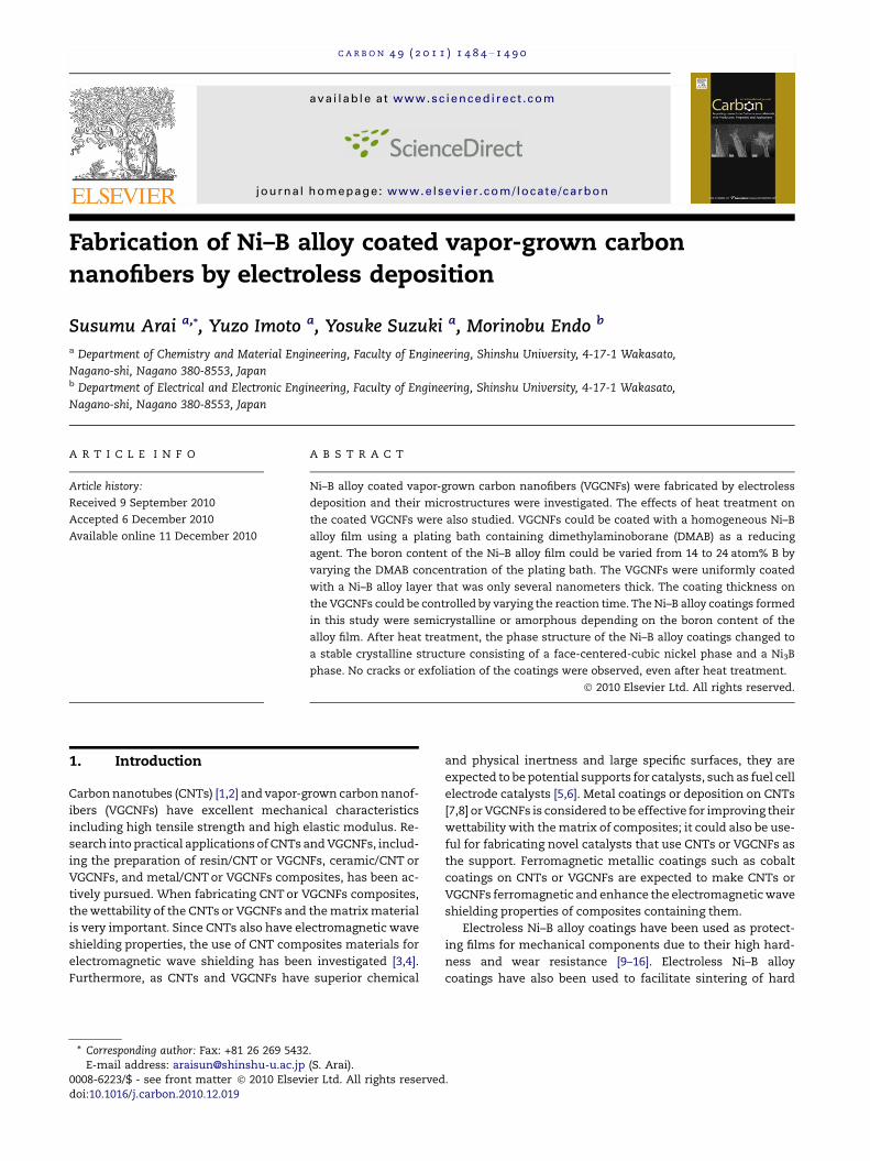
Fig. 1 – SEM image of Ni–B alloy coated VGCNFs produced by
electroless deposition at pH = 8. The DMAB concentration
was 0.05 M and the reaction time was 600 s.
2. Experimental
2.1. Chemicals
Commercially available VGCNFs (VGCFs, Showa Denko Co.
Ltd.) were used in the present study. The VGCFs had a
diameter of 150 nm and a length of 10 lm. The VGCFs are
graphitized VGCNFs that had been heat treated at 2800 �Cin argon gas for 30 min [28]. NiSO4Æ6H2O, C6H5Na3O7Æ2H2O,
dimethylaminoborane (DMAB), SnCl2ÆH2O, and PdCl2 (Wako
Pure Chemical Industries, Ltd.) were used in this study;
they are special-grade reagents. First-grade polyacrylic
acid with a mean molecular weight of 5000 (PA-5000, Wako
Pure Chemical Industries, Ltd.) was used to disperse the
VGCNFs. Pure water from an electrodialysis water purifier
(RFP343RA, Advantec MFS, Inc.) was used in all experi-
ments.
2.2. Sensitization and activation of the VGCNFs
Since VGCNFs are hydrophobic, the VGCNFs were first dis-
persed in an aqueous solution of PA-5000 that was agitated
using a stirrer and ultrasonic irradiation. After dispersion,
the VGCNFs were filtered and added to a 4.4 · 10�2 M SnCl2Æ2-
H2O + 0.12 M HCl solution at 25 �C with agitation (ultrasonic
irradiation: 1 min, stirrer agitation: 5 min) to absorb Sn2+ ions
on the VGCNFs (sensitization). After filtering, the VGCNFs
were then immersed in a 5.6 · 10�4 M PdCl2 + 0.12 M HCl solu-
tion at 25 �C with agitation (ultrasonic irradiation: 1 min, stir-
rer agitation: 5 min) to form palladium catalytic nuclei on the
VGCNFs (activation).
2.3. Electroless Ni–B alloy deposition on VGCNFs
After activation, the VGCNFs were placed in electroless plating
baths for Ni–B alloy deposition. The electroless plating bath
composition used was 0.1 M NiSO4Æ6H2O + 0.1 M Na3C6H5O7 + x
M DMAB. The bath pH was varied from 4 to 10. Electroless plat-
ing was performed with stirrer agitation at 30 �C.
2.4. Heat-treatment of Ni–B alloy deposited VGCNFs
The Ni–B alloy coated VGCNFs were heated at various temper-
atures for 1 h in an infrared heating furnace (mini lamp
annealer; MILA-3000, Ulvac-Riko Inc.) in vacuum.
2.5. Characterization of electroless Ni–B alloy deposits onVGCNFs
The Ni–B alloy deposits on the VGCNFs were observed by
field-emission scanning electron microscopy (SEM; JSM-
7000F, Jeol and SU-8000, Hitachi) and scanning transmission
electron microscopy (STEM; HD-2300A, Hitachi). The phase
structures of the deposits were analyzed by X-ray diffraction
(XRD) using Cu Ka1 radiation (XRD-6000, Shimadzu Seisaku-
sho). The boron content of the Ni–B alloy coating was mea-
sured by inductively coupled plasma spectroscopy (ICPS;
ICPS-7500, Shimadzu Seisakusho). The phase transition
behavior of the Ni–B alloy film was evaluated by differential
scanning calorimetry (DSC; DSC8230SF, Rigaku). The amount
of deposited Ni–B alloy was determined by weighing. For this,
Ni–B alloy deposited VGCNFs were dried and weighed. The Ni–
B alloy deposits were then dissolved in nitric acid. The
VGCNFs in the nitric acid solution were filtered, dried, and
weighed. The volume of the deposited Ni–B alloy was calcu-
lated by dividing the weight of the deposited Ni–B alloy by
its density. The mean density was calculated based on the
individual densities of nickel and boron. The mean thickness
of the Ni–B alloy coating on the VGCNFs was roughly calcu-
lated by dividing the volume of the deposited Ni–B alloy by
the surface area of the VGCNFs. The surface area of the
VGCNFs was taken to be 13 m2 g�1.
3. Results and discussion
The electroless deposition behavior of Ni–B alloy on VGCNFs
varied considerably with the bath pH. No deposits were ob-
served on the VGCNFs at a pH of 4. At pH of 6 and 10, small
amounts of inhomogeneous deposits were observed on the
VGCNFs. Homogeneous deposition of Ni–B alloy on the
VGCNFs was obtained at pH = 8. Fig. 1 shows an SEM image
of Ni–B alloy-deposited VGCNFs fabricated using a plating
bath containing 0.05 M DMAB at pH = 8. The reaction time
was 600 s. Each VGCNF is homogeneously coated with the
Ni–B alloy. Therefore, a bath pH of 8 was used in subsequent
experiments in this study.
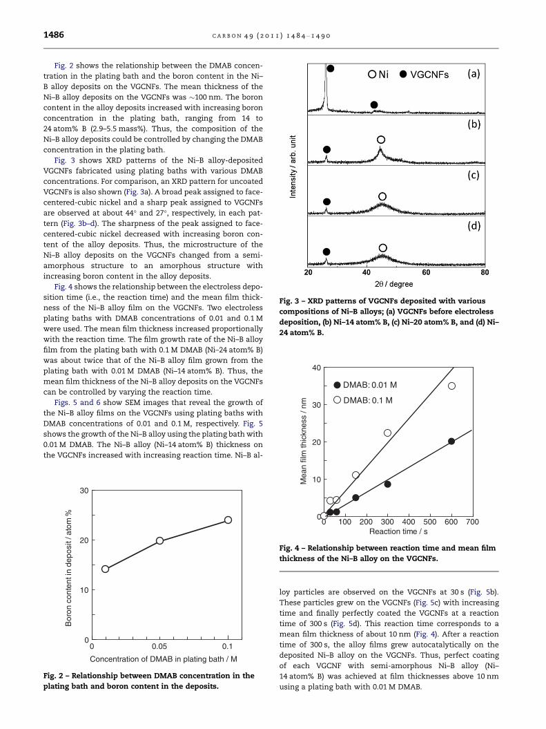
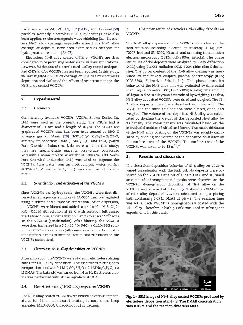
Fig. 3 – XRD patterns of VGCNFs deposited with various
compositions of Ni–B alloys; (a) VGCNFs before electroless
deposition, (b) Ni–14 atom% B, (c) Ni–20 atom% B, and (d) Ni–
24 atom% B.
20
30
40
DMAB: 0.01 M
DMAB: 0.1 M
film
thic
knes
s / n
m
1486 C A R B O N 4 9 ( 2 0 1 1 ) 1 4 8 4 – 1 4 9 0
Fig. 2 shows the relationship between the DMAB concen-
tration in the plating bath and the boron content in the Ni–
B alloy deposits on the VGCNFs. The mean thickness of the
Ni–B alloy deposits on the VGCNFs was �100 nm. The boron
content in the alloy deposits increased with increasing boron
concentration in the plating bath, ranging from 14 to
24 atom% B (2.9–5.5 mass%). Thus, the composition of the
Ni–B alloy deposits could be controlled by changing the DMAB
concentration in the plating bath.
Fig. 3 shows XRD patterns of the Ni–B alloy-deposited
VGCNFs fabricated using plating baths with various DMAB
concentrations. For comparison, an XRD pattern for uncoated
VGCNFs is also shown (Fig. 3a). A broad peak assigned to face-
centered-cubic nickel and a sharp peak assigned to VGCNFs
are observed at about 44� and 27�, respectively, in each pat-
tern (Fig. 3b–d). The sharpness of the peak assigned to face-
centered-cubic nickel decreased with increasing boron con-
tent of the alloy deposits. Thus, the microstructure of the
Ni–B alloy deposits on the VGCNFs changed from a semi-
amorphous structure to an amorphous structure with
increasing boron content in the alloy deposits.
Fig. 4 shows the relationship between the electroless depo-
sition time (i.e., the reaction time) and the mean film thick-
ness of the Ni–B alloy film on the VGCNFs. Two electroless
plating baths with DMAB concentrations of 0.01 and 0.1 M
were used. The mean film thickness increased proportionally
with the reaction time. The film growth rate of the Ni–B alloy
film from the plating bath with 0.1 M DMAB (Ni–24 atom% B)
was about twice that of the Ni–B alloy film grown from the
plating bath with 0.01 M DMAB (Ni–14 atom% B). Thus, the
mean film thickness of the Ni–B alloy deposits on the VGCNFs
can be controlled by varying the reaction time.
Figs. 5 and 6 show SEM images that reveal the growth of
the Ni–B alloy films on the VGCNFs using plating baths with
DMAB concentrations of 0.01 and 0.1 M, respectively. Fig. 5
shows the growth of the Ni–B alloy using the plating bath with
0.01 M DMAB. The Ni–B alloy (Ni–14 atom% B) thickness on
the VGCNFs increased with increasing reaction time. Ni–B al-
0 0.05 0.10
10
20
30
Concentration of DMAB in plating bath / M
Bor
on c
onte
nt in
dep
osit
/ ato
m
Fig. 2 – Relationship between DMAB concentration in the
plating bath and boron content in the deposits.
0 100 200 300 400 500 600 7000
10
Reaction time / s
Mea
n
Fig. 4 – Relationship between reaction time and mean film
thickness of the Ni–B alloy on the VGCNFs.
loy particles are observed on the VGCNFs at 30 s (Fig. 5b).
These particles grew on the VGCNFs (Fig. 5c) with increasing
time and finally perfectly coated the VGCNFs at a reaction
time of 300 s (Fig. 5d). This reaction time corresponds to a
mean film thickness of about 10 nm (Fig. 4). After a reaction
time of 300 s, the alloy films grew autocatalytically on the
deposited Ni–B alloy on the VGCNFs. Thus, perfect coating
of each VGCNF with semi-amorphous Ni–B alloy (Ni–
14 atom% B) was achieved at film thicknesses above 10 nm
using a plating bath with 0.01 M DMAB.
Fig. 5 – SEM images showing the growth of Ni–B alloy deposits on VGCNFs using an electroless plating bath with 0.01 M
DMAB (a) before electroless deposition and (b) after 30, (c) 150, and (d) 300 s.
Fig. 6 – SEM images showing growing process of Ni–B alloy deposits on VGCNFs from a plating bath with 0.1 M DMAB; (a)
before electroless deposition, (b) 30, (c) 150, and (d) 300 s.
C A R B O N 4 9 ( 2 0 1 1 ) 1 4 8 4 – 1 4 9 0 1487
Fig. 6 shows the growth of the Ni–B alloy on the VGCNFs
using the electroless plating bath with 0.1 M DMAB. The Ni–
B alloy (Ni–24 atom% B) deposits grew on the VGCNFs with
increasing reaction time. In contrast with Fig. 5, the VGCNFs
in this case were coated perfectly even at a reaction time of
30 s (Fig. 6b), which corresponds to a film thickness of about
4 nm (Fig. 4). Subsequently, the alloy films grew autocatalyti-
cally on the deposited Ni–B alloy on the VGCNFs (Fig. 6c
and d). The surface morphology was smoother than the Ni–
14 atom% B alloy deposits.
Fig. 7 shows STEM images of the Ni–B alloy deposits on the
VGCNFs from plating baths with DMAB concentrations of 0.01
and 0.1 M for a reaction time of 30 s. Fig. 7a and d shows STEM
images of pristine VGCNFs (Fig. 7d: high magnification). A
number of particles with diameters of several nanometers
are visible on the VGCNFs from the plating bath with 0.01 M
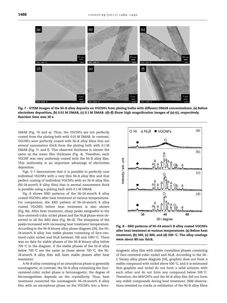
Fig. 7 – STEM images of the Ni–B alloy deposits on VGCNFs from plating baths with different DMAB concentrations. (a) Before
electroless deposition, (b) 0.01 M DMAB, (c) 0.1 M DMAB. (d)–(f) Show high magnification images of (a)–(c), respectively.
Reaction time was 30 s.
Fig. 8 – XRD patterns of Ni–24 atom% B alloy coated VGCNFs
after heat treatment at various temperatures. (a) Before heat
treatment, (b) 300, (c) 400, and (d) 500 �C. The alloy coatings
were about 80 nm thick.
1488 C A R B O N 4 9 ( 2 0 1 1 ) 1 4 8 4 – 1 4 9 0
DMAB (Fig. 7b and e). Thus, the VGCNFs are not perfectly
coated from the plating bath with 0.01 M DMAB. In contrast,
VGCNFs were perfectly coated with Ni–B alloy films that are
several nanometers thick from the plating bath with 0.1 M
DMAB (Fig. 7c and f). This observed thickness is almost the
same as the mean film thickness (Fig. 4). Therefore, each
VGCNF was very uniformly coated with the Ni–B alloy film.
This uniformity is an important advantage of electroless
deposition.
Figs. 5–7 demonstrate that it is possible to perfectly coat
individual VGCNFs with a very thin Ni–B alloy film and that
perfect coating of individual VGCNFs with an Ni–B alloy film
(Ni–24 atom% B alloy film) that is several nanometers thick
is possible using a plating bath with 0.1 M DMAB.
Fig. 8 shows XRD patterns of the Ni–24 atom% B alloy
coated VGCNFs after heat treatment at various temperatures.
For comparison, the XRD pattern of Ni–24 atom% B alloy
coated VGCNFs before heat treatment is also shown
(Fig. 8a). After heat treatment, sharp peaks assignable to the
face-centered-cubic nickel phase and the Ni3B phase were ob-
served in all the XRD data (Fig. 8b–d). The sharpness of the
peaks increased with increasing heat treatment temperature.
According to the Ni–B binary alloy phase diagram [29], the Ni–
24 atom% B alloy has stable phases consisting of face-cen-
tered-cubic nickel and Ni3B between 700 and 1093 �C. There
was no data for stable phases of the Ni–B binary alloy below
700 �C in the diagram. If the stable phases of the Ni–B alloy
below 700 �C are the same as those above 700 �C, the Ni–
24 atom% B alloy film will have stable phases after heat
treatment.
A Ni–B alloy consisting of an amorphous phase is generally
nonmagnetic; in contrast, the Ni–B alloy containing the face-
centered-cubic nickel phase is ferromagnetic; the degree of
ferromagnetism depends on the crystallinity. Thus, heat
treatment converted the nonmagnetic Ni–24 atom% B alloy
film with an amorphous phase on the VGCNFs into a ferro-
magnetic alloy film with stable crystalline phases consisting
of face-centered-cubic nickel and Ni3B. According to the Ni–
C binary alloy phase diagram [29], graphite does not form a
stable compound with nickel above 500 �C, and it is estimated
that graphite and nickel do not form a solid solution with
each other and do not form any compound below 500 �C.
Therefore, the MWCNTs and the Ni–B alloy film did not form
any stable compounds during heat treatment. SEM observa-
tions revealed no cracks or exfoliation of the Ni–B alloy films
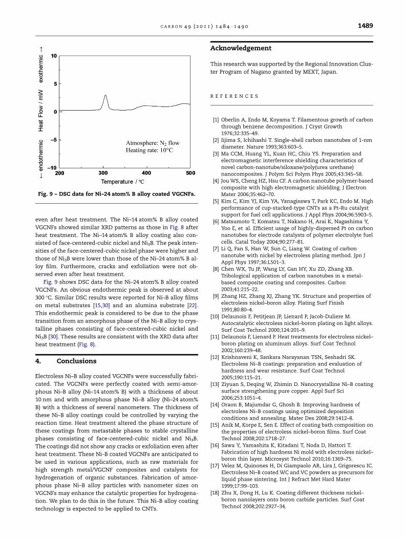
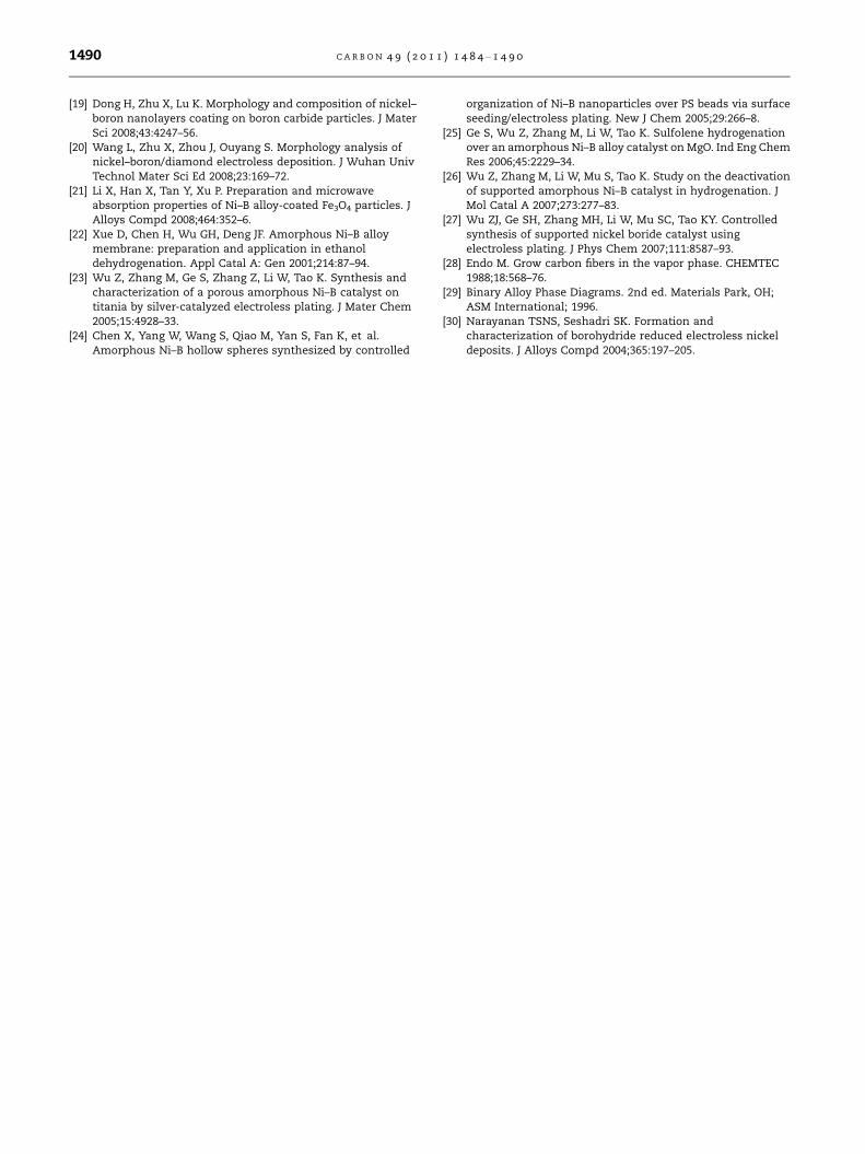
Fig. 9 – DSC data for Ni–24 atom% B alloy coated VGCNFs.
C A R B O N 4 9 ( 2 0 1 1 ) 1 4 8 4 – 1 4 9 0 1489
even after heat treatment. The Ni–14 atom% B alloy coated
VGCNFs showed similar XRD patterns as those in Fig. 8 after
heat treatment. The Ni–14 atom% B alloy coating also con-
sisted of face-centered-cubic nickel and Ni3B. The peak inten-
sities of the face-centered-cubic nickel phase were higher and
those of Ni3B were lower than those of the Ni–24 atom% B al-
loy film. Furthermore, cracks and exfoliation were not ob-
served even after heat treatment.
Fig. 9 shows DSC data for the Ni–24 atom% B alloy coated
VGCNFs. An obvious endothermic peak is observed at about
300 �C. Similar DSC results were reported for Ni–B alloy films
on metal substrates [15,30] and an alumina substrate [22].
This endothermic peak is considered to be due to the phase
transition from an amorphous phase of the Ni–B alloy to crys-
talline phases consisting of face-centered-cubic nickel and
Ni3B [30]. These results are consistent with the XRD data after
heat treatment (Fig. 8).
4. Conclusions
Electroless Ni–B alloy coated VGCNFs were successfully fabri-
cated. The VGCNFs were perfectly coated with semi-amor-
phous Ni–B alloy (Ni–14 atom% B) with a thickness of about
10 nm and with amorphous phase Ni–B alloy (Ni–24 atom%
B) with a thickness of several nanometers. The thickness of
these Ni–B alloy coatings could be controlled by varying the
reaction time. Heat treatment altered the phase structure of
these coatings from metastable phases to stable crystalline
phases consisting of face-centered-cubic nickel and Ni3B.
The coatings did not show any cracks or exfoliation even after
heat treatment. These Ni–B coated VGCNFs are anticipated to
be used in various applications, such as raw materials for
high strength metal/VGCNF composites and catalysts for
hydrogenation of organic substances. Fabrication of amor-
phous phase Ni–B alloy particles with nanometer sizes on
VGCNFs may enhance the catalytic properties for hydrogena-
tion. We plan to do this in the future. This Ni–B alloy coating
technology is expected to be applied to CNTs.
Acknowledgement
This research was supported by the Regional Innovation Clus-
ter Program of Nagano granted by MEXT, Japan.
R E F E R E N C E S
[1] Oberlin A, Endo M, Koyama T. Filamentous growth of carbonthrough benzene decomposition. J Cryst Growth1976;32:335–49.
[2] Iijima S, Ichihashi T. Single-shell carbon nanotubes of 1-nmdiameter. Nature 1993;363:603–5.
[3] Ma CCM, Huang YL, Kuan HC, Chiu YS. Preparation andelectromagnetic interference shielding characteristics ofnovel carbon-nanotube/siloxane/poly(urea urethane)nanocomposites. J Polym Sci Polym Phys 2005;43:345–58.
[4] Jou WS, Cheng HZ, Hsu CF. A carbon nanotube polymer-basedcomposite with high electromagnetic shielding. J ElectronMater 2006;35:462–70.
[5] Kim C, Kim YJ, Kim YA, Yanagisawa T, Park KC, Endo M. Highperformance of cup-stacked-type CNTs as a Pt–Ru catalystsupport for fuel cell applications. J Appl Phys 2004;96:5903–5.
[6] Matsumoto T, Komatsu T, Nakano H, Arai K, Nagashima Y,Yoo E, et al. Efficient usage of highly-dispersed Pt on carbonnanotubes for electrode catalysts of polymer electrolyte fuelcells. Catal Today 2004;90:277–81.
[7] Li Q, Fan S, Han W, Sun C, Liang W. Coating of carbonnanotube with nickel by electroless plating method. Jpn JAppl Phys 1997;36:L501–3.
[8] Chen WX, Tu JP, Wang LY, Gan HY, Xu ZD, Zhang XB.Tribological application of carbon nanotubes in a metal-based composite coating and composites. Carbon2003;41:215–22.
[9] Zhang HZ, Zhang XJ, Zhang YK. Structure and properties ofelectroless nickel–boron alloy. Plating Surf Finish1991;80:80–4.
[10] Delaunois F, Petitjean JP, Lienard P, Jacob-Duliere M.Autocatalytic electroless nickel–boron plating on light alloys.Surf Coat Technol 2000;124:201–9.
[11] Delaunois F, Lienard P. Heat treatments for electroless nickel–boron plating on aluminum alloys. Surf Coat Technol2002;160:239–48.
[12] Krishnaveni K, Sankara Narayanan TSN, Seshadri SK.Electroless Ni–B coatings: preparation and evaluation ofhardness and wear resistance. Surf Coat Technol2005;190:115–21.
[13] Ziyuan S, Deqing W, Zhimin D. Nanocrystalline Ni–B coatingsurface strengthening pure copper. Appl Surf Sci2006;253:1051–4.
[14] Oraon B, Majumdar G, Ghosh B. Improving hardness ofelectroless Ni–B coatings using optimized depositionconditions and annealing. Mater Des 2008;29:1412–8.
[15] Anik M, Korpe E, Sen E. Effect of coating bath composition onthe properties of electroless nickel–boron films. Surf CoatTechnol 2008;202:1718–27.
[16] Sawa Y, Yamashita K, Kitadani T, Noda D, Hattori T.Fabrication of high hardness Ni mold with electroless nickel–boron thin layer. Microsyst Technol 2010;16:1369–75.
[17] Velez M, Quinones H, Di Giampaolo AR, Lira J, Grigorescu IC.Electroless Ni–B coated WC and VC powders as precursors forliquid phase sintering. Int J Refract Met Hard Mater1999;17:99–103.
[18] Zhu X, Dong H, Lu K. Coating different thickness nickel–boron nanolayers onto boron carbide particles. Surf CoatTechnol 2008;202:2927–34.
1490 C A R B O N 4 9 ( 2 0 1 1 ) 1 4 8 4 – 1 4 9 0
[19] Dong H, Zhu X, Lu K. Morphology and composition of nickel–boron nanolayers coating on boron carbide particles. J MaterSci 2008;43:4247–56.
[20] Wang L, Zhu X, Zhou J, Ouyang S. Morphology analysis ofnickel–boron/diamond electroless deposition. J Wuhan UnivTechnol Mater Sci Ed 2008;23:169–72.
[21] Li X, Han X, Tan Y, Xu P. Preparation and microwaveabsorption properties of Ni–B alloy-coated Fe3O4 particles. JAlloys Compd 2008;464:352–6.
[22] Xue D, Chen H, Wu GH, Deng JF. Amorphous Ni–B alloymembrane: preparation and application in ethanoldehydrogenation. Appl Catal A: Gen 2001;214:87–94.
[23] Wu Z, Zhang M, Ge S, Zhang Z, Li W, Tao K. Synthesis andcharacterization of a porous amorphous Ni–B catalyst ontitania by silver-catalyzed electroless plating. J Mater Chem2005;15:4928–33.
[24] Chen X, Yang W, Wang S, Qiao M, Yan S, Fan K, et al.Amorphous Ni–B hollow spheres synthesized by controlled
organization of Ni–B nanoparticles over PS beads via surfaceseeding/electroless plating. New J Chem 2005;29:266–8.
[25] Ge S, Wu Z, Zhang M, Li W, Tao K. Sulfolene hydrogenationover an amorphous Ni–B alloy catalyst on MgO. Ind Eng ChemRes 2006;45:2229–34.
[26] Wu Z, Zhang M, Li W, Mu S, Tao K. Study on the deactivationof supported amorphous Ni–B catalyst in hydrogenation. JMol Catal A 2007;273:277–83.
[27] Wu ZJ, Ge SH, Zhang MH, Li W, Mu SC, Tao KY. Controlledsynthesis of supported nickel boride catalyst usingelectroless plating. J Phys Chem 2007;111:8587–93.
[28] Endo M. Grow carbon fibers in the vapor phase. CHEMTEC1988;18:568–76.
[29] Binary Alloy Phase Diagrams. 2nd ed. Materials Park, OH;ASM International; 1996.
[30] Narayanan TSNS, Seshadri SK. Formation andcharacterization of borohydride reduced electroless nickeldeposits. J Alloys Compd 2004;365:197–205.


![12-01-02 CarboMetal Poster€¦ · powder [SPS: Spark Plasma Sintering, HIP: Hot Isostatic Pressing] Synthesis of Al- and Cu-coated CNTs (Electroless Plating Process / Chemical and](https://img.pdfslide.net/doc/110x75/6085964762a9da2c892a410e/12-01-02-carbometal-powder-sps-spark-plasma-sintering-hip-hot-isostatic-pressing.jpg)