Embed Size (px)
Citation preview

FD-8142 957 SOME FACTORS AFFECTING THE SELECTION OF THE TYPE OF NEW i/iTRANSONIC TUNNEL T. (U) AERONAUTICAL RESEARCH LABS
NCLAS MELBOURNE (AUSTRALIA) N POLLOCK( DEC 83 ARL/AERO TM-359 N
UNLSSFE F/G 14/'2
MEUEEENEE IEND
I lflllllfff

II 1.25 3.2 .
1.25

'S / 1-'*AR-002-995
In0)NDEPARTMENT OF DEFENCEV DEFENCE SCIENCE AND TECHNOLOGY ORGANISATION
AERONAUTICAL RESEARCH LABORATORIES
IElUOUmE. VICTORIA
mftozm cs fdmica1 NGMz-nm 359
SOW FACTORS AFFECTING THE SELECTIONOF THE TYPE OF NEW TRANSONC TUNNEL
TO BEST MEET AUSTRALIAN NEEDS
by
DTICI i ILECTE
meow TEHNC IfOTuiO MAS& S JUL 0 %
0 ITHE UNITED STATES NATIONALE:3 AUTHCIs,:-u TO
RP'ODUOE AMD SULL TI W T I(c) owin ow§ 2A 163
V,. -A 11963
UNCLASSIFIEDANt~& 018

AR-002-995
. 'DEPARTMEhT OF DEFENCE
DEFENCE SCIENCE AND TECH =OGY ORGANISATION
AERO LTIC'AL ESEARC LB-RAODRIES
Aerodynamics Technical Memorandum 359
SOME FACTORS AFFECTING THE SELECTIONOF THE TYPE OF NEW TRANSONIC TUNNEL
TO BEST MEET AUSTRALIAN NEEDS
by
N. POLLOCK
r SUMMARY
A consideration of the new transonic wind tunnel optionsidentified at the Dec. 1982 workshop held at ARL is presented.Factors discussed include, Reynolds number requirements, test sectiondimensions, operating pressure, individual run duration, totalavailable testing time and operating costs.
It is concluded that, despite the lower test Reynolds numbercapability, a continuous flow, conventional fan driven tunnel is moresuited to Australian requirements than an intermittent blowdown tunnel.If a significant supersonic requirement existed this preference wouldprobably be reversed.
CD C4ONWLALTH OF AUSTFALIA 19E2
PCSTA ADDRESS: Director, Aeronautical Research Laboratcries,P.O. box 4331, Melbourne, Victcria, 3001, Australia.

.~ .' C * S St *S. . ....... .5.. .-... -- -.7- -
CONTENTS
PAGE NO.
1. INTRODUCTION 1
2. FACTORS AFFECTING TUNNEL SELECTION 1
2.1 Reynolds Number Requirements 1
4-., S2.2 Test Section Dimensions 3
2.3 Operating Pressure 4
2.4 Individual Run Duration 5
2.5 Total Available Testing Time 5
2.6 Operating Costs 6
3. COMPARISON BETWEEN BLOWDOWN AND CONTINUOUSFLOW TUNNELS 7
4. CONCLUSION 9
REFERENCES
DISTRIBUTION
DOCUMENT CONTROL DATA
Accession ForNTIS GRA&IDTIC TABTJustificatio
Distribut ion/
Availability CodesAva ii and/or
Dist Special

1. INTRODUCTION
Following a recommendation from the Australian, Science andTechnology Council (ASTEC) lan investigation into new aerodynamic testfacility requirements for Australia has been carried out at ARL andWSRL. A survey of the needs for such new facilities and ways in whichthe identified needs could be met are presented in References 2 and 3.As part of this investigation two prominent international wind tunneldesign consultants, DSMA International Inc. of Toronto, Canada andSverdrup Technology Inc. of Tullahoma, USA, were engaged to undertakeconceptural design studies of new wind tunnels to meet Australian needs.On the 9th and 10th of December 1982 a workshop4 on the topic "NeedsFor More Capable Wind Tunnels in Defence Support Laboratories" wasconducted at ARL. This workshop was attended by representatives fromthe Defence Forces, Industry, Research Organizations and AcademicInstitutions.
From the investigations conducted at ARL and WSRL, therecommendations of the two consultants and the conclusions reached atthe workshop there is overwhelming agreement that a new transonic windtunnel for Australia is urgently required. It is also clear from thework carried out up to now that the only practical facility types to meetlocal needs are a continuous flow closed circuit, compressor driventunnel or an intermittent blowdown tunnel.
Neither of these tunnels meets all of our requirements and anassessment of the advantages and disadvantages of the two types isrequired. It is the aim of this paper to contribute to this assessment.
2. FACTORS AFFECTING TUNNEL SELECTION
2.1 Reynolds Number Requirements
One of the important areas in which the capabilities of the twocontending tunnel types differs is that of available test Reynoldsnumber. Based on the costing information provided by the consultantsit appears that for a blowdown tunnel costing about $25M (1981Australian Dollars) a maximum Reynolds number (Re) of 10 X 10 6 to13 X i06 (based on 0.1 X vTest section area) is available in the transonicspeed range. This Re meets the requirement suggested in Reference 3which was formulated on the basis of arguments presented in Reference5. For a continuous tunnel of the same cost a maximum test Re abouthalf that of a blowdown tunnel would be available. Since this Redifference is such a fundamental factor it was considered worthwhile toreassess its importance.
During the past decade there have been a number 5-9 of investigations
* into what test Re is required to achieve an acceptable representationof the full scale flow. Viewed critically, there is some evidence tosuggest that the conclusion as to the minimum acceptable test Re reachedin these investigations was influenced by the capabilities of the facilitywhich was planned at the time. There also appears to be a trend formore recent investigations to recommend a higher Re. The situation nowappears to have been reached in the USA and Europe where the consensus ofopinion is that nothing short of full scale Re's are required. The

71. 71 V Pr, -. -W 77:
-2-
conviction with which this view is held is evidenced by the construction*< of the NTF in the USA and the advanced planning of the ETW in Europe.
It has been argued that these extreme test Re requirements are onlyrelevant to high aspect ratio transport configurations and not to combataircraft. In an attempt to test this assertion a survey of publishedtest results on various configurations was undertaken.
Over the years there have been an enormous number of tests onaircraft configurations many of which contain information of the effectof Re. Unfortunately they also contain information on tunnel flowquality, wall interference, model fidelity, model aeroelastic behavious
*and support interference. In virtually all cases it is difficult, ifnot impossible, to positively identify the contribution of the variousfactors mentioned above. This is graphically demonstrated by the NACA0012 lift curve slope data (Fig 1) presented by McCroskey during thediscussion at the May 1982 AGAR: conference on Wall Interference in
4 Wind Tunnels2 . However in the Author's view the following conclusionsqregarding Re can be drawn.
a. Different aircraft configurations vary widely in their Resensitivity. This sensitivity is also highly dependent on the part ofthe operational envelope under consideration. Generalizations on Resensitivity are difficult. Significant effects have been noted at Machnumbers from 0.16 to 1.0, for high and low lift conditions and for bothhigh and low aspect ratio configurations.
b. There is general agreement that a chord Re of 1 X 10⁶ is theabsolute minimum for any worthwhile testing regardless of configuration.The evidence suggests that this should be viewed as a minimum tip chordRe rather than simply a mean chord Re.
C. There is no convincing evidence that there is any generallyapplicable sub full scale Re above which Re effects can be neglected.The best controlled experiments (see for example Reference 10), whichunfortunately only extend to a chord Re of 5 X 10⁶, show a steadymonotonic change of a Re sensitive parameters throughout the test range.
d. For particular configurations at particular test conditionsthere is the possibility of a minimum acceptable Re below which the testflow pattern is completely different from the full scale one. Thisoccurs most conmmonly when the nature of the stall changes1 , say fromthe thin aerofoil type to the leading edge type.
There is no generally applicable Re for these discontinuousflow changes and the only defence against them is an awareness on the partof the test engineer of the fundamental flow conditions on the model he
* is testing.
e. For many, but not all, configurations there is a chord Re in therange 2.5 X 10⁶ to 4 X 10 6 where higher Re conditions can be simulatedusing the trick of aft transition fixing 12. It would be clearlyadvantageous for a wind tunnel to have access to the Re range.
f. To facilitate the extrapolation of test results to full scaleit is helpful if the test Re can be varied over a range of at least 2 to 1.

-3-
The best controlled investigations into the effect of test Re havebeen carried out on two dimensional aerofoils. Despite the fact thatthese tests are highly idealized they can give considerable insight into
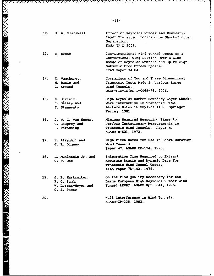
.0 the behaviour of full aircraft configurations. These tests13-15 show thatV the characteristics of most aerofcil sections are still changing significantly
at Re values of 30 X i0 to 40 X 106. These Re's are well into thefull scale flight range. For some modern supercritical sections thisRe effect is quite large as shown in Figure 2 which is redrawn fromReference 15.
On the basis of the factors discussed in this section the followingobservations on the Re requirements of new tunnels can be made:
a. The highest possible test Re consistent with tunnel cost andthe appearance of other adverse tunnel operating characteristics isrequired. However there is no Re value above 1 X 10⁶ (based on chord)which separates acceptable from fundamentally unacceptable testingcapability.
b. The tunnel should be capable of testing over a Re range of at least2 to 1 in the Mach number range 0.5 to 1.4 without dropping below theminimum value of I X 10.
c. It would be highly advantageous for the tunnel to be capable ofoperating at chord Re values of 2.5 X 10⁶ to 4 X 10⁶ in the high subsonicspeed range.
These requirements do not preclude either of the proposed tunneltypes but favour the higher Re capability of the blowdown tunnel.
2.2 Test Section Dimensions
The test section dimensions are a fundamental parameter which mustbe established early in a tunnel design program. These dimensions areparticularly critical because the tunnel cost, irrespective of type, varywith the linear dimensions raised to a power between 2 and 3. Consideringfirst the test section shape; there is a high level of agreement thata square shape is the best compromise for general aircraft testing.Turning to size; the most important impact of test section dimensions,apart from the obvious effect on Re, is on the design and manufacture oftest models. There is general agreement that aircraft models withextensive pressure tappings or with remotely set control actuators cannotbe economically manufactured with a span less than 0.6m to 0.8m. Basedon this fact and the current state of knowledge on wall interference, bothconsultants agreed that the minimum practical test section size is1.5m X 1.5m.
The author considers that there is evidence that a larger testsection size would be needed for very complex models involving manyadjustable control surfaces and/or representative elastic structures,like for example the FA-18. There is strong evidence that the cost of atunnel with a test section 2m square or larger would be prohibitive. Thepossible range of test section dimensions is therefore in the range 1.5mto 2m. The advantages acruing from small increases in the test sectionsize should not be underestimated. Although the Re gain is negligable thegreater freedom in model design may make very large differences to testaccuracy and productivity.

,AX .. I T N . .-.
-4-
2.3 Operating Pressure
There is general agreement that any tunnel suitable for Australiawould use ambient temperature air as a test gas and as pointed out in theprevious section, the practical range of test section sizes is verylimited. These two facts combine to leave the use of high stagnationpressure as the only path to increased test Re. The Re difference betweenthe continuous flow and blowdown options reflects their different operatingpressures. For a practical blowdown tunnel the maximum stagnationpressure in the transonic speed range, set by minimum run time considerations,is about 700 kPa and the minimum pressure, set by the atmospheric exhauststarting limit, is about 150 kPa. For a practical continuous flow tunnelof similar cost to a blowdown tunnel the maximum stagnation pressure, setby cost and peak power considerations is about 300 kPa and the onlyminimur pressure limit is set by the capacity of the tunnel pressurisationplant.
As higher tunnel pressures are utilised increasing problems withmodel strength, support strength and non representative aeroelasticdistortions would be experienced. An investigation5 into these problemsconcluded that for the high strength steels currently used for windtunnel models (ultimate tensile strength 1.0 GNm- ) the static pressurefor high lift testing should be limited to 280 kPa at transonic speeds.This is equivalent to a stagnation pressure of about 450 kPa. If maraging
2steels with an ultimate strength of around 2.0 Gm - were used thisstagnation pressure limit would be around 900 kPa. Unfortunately thesesteels are difficult to fabricate and have rather poor fatigue properties.For these limiting stagnation pressures the supporting sting requiredfor the model would contribute significant interference and in mostcases involve quite considerable modifications to the geometry of therear of the model. It would also preclude any intake flow modelling.The situation regarding aeroelastic distortion at these high pressuresis described very well in Reference 5 and conclusion from the appropriatesection of that Reference is reproduced below:
"The main conclusion to draw from this section is that even over
the restricted range of flight conditions for which model tests at highReynolds number might be thought necessary in order to simulate full-scaleflows on current aircraft, the model wing may differ from the aircraftshape by up to 0.4* of twist. From the results of deve*opment tests oftransport aircraft and of combat aircraft with simulated manoeuvredistortions, it appears that changes in wing twist of this magnitude canhave significant effects on stability and buffet margins. Greatererrors would be present for future aircraft if it turns out that therange of tests on one model has to be extended to cover flight conditionsdown to lg and more than one model might be needed to provide an alternativedatum. For the more highly - tapered and more highly - swept wings ofsome possible transport aircraft and, again for most combat aircraft, therate of change of model wing distortion with lift coefficient, for amodel with solid wings, may exceed that for the aircraft at high cruisingaltitude and hence there is no scope for improved aeroelastic modellingother than by reducing tunnel pressure. The model scale must be suchthat the Reynolds number does not fall too far in consequence of thisneed to work at lower pressures."
It must be remembered that the above conclusion was written in1971 well before very elastic aircraft like the F/A-IS entered service.oTh situation today is therefore considerable mzre difficult than the
above words imply.

- - . .. P ' j '. ; . -. . . .' - . : . .. . ' . .: - . .. . .' ..
-'5- [
On the basis of the material presented in this section theAuthor considers that it is doubtful whether testing at above about400 kPa stagnation pressure yields any significant increase in dataaccuracy. The gains from better Re scaling are likely to be largelyoffset by errors introduced by support interference and non-representativeaeroelastic deflections.
It should be noted that all the above conclusions are based onthe use of solid steel models. If more complex models incorporatingpressure tappings, mechanically actuated control surfaces or elasticallyscaled structures were used, the tunnel operating pressure would haveto be further restricted. One class of complex test which is of particularimportance to Australia is that of captive trajectory store release. Itis understood that in the AEDC 4T tunnel where much of the USA's storerelease work is carried out, it is normal practice to use stagnationpressure equal to or below atmospheric. The reductions in model andsupporting rig deflections are judged to be of greater importance thanthe loss in Re.I<
Current forecasts of materials developments over the next 30 yearssuggest that, for practical engineering materials suitable for modelmanufacture, gains in stiffness and strength of only about 50% overcurrent maraging steels are possible. During a recent overseas trip bythe Author there was a consensus of opinion among major tunnel operatorsthat advanced materials would not lead to significantly stronger orstiffer models in the foreseeable future.
The implication of the above considerations is that much of theRe advantage of the blowdown over the continuous flow tunnel cannot beused effectively for many tests. This clearly reduces the realimportance of the Re difference between the two facility types.
2.4 Individual Run Duration
Blowdown tunnels of the type under consideration have a maximumrun duration which varies from about 10 sec at the maximum Re to about60 sec at the minimum operating Re. Continuous compressor drive tunnelswith adequate installed cooling capacity have no inherent run durationlimit. It is generally agreed that all normal static and dynamic 1 transonictests can be carried out in less than 10 sec. It is known that at leastone blowdown tunnel in the world has the capability to carry out captivetrajectory store release tests, presumably only near its lowest Re.However there is no doubt that store release tests would be easier ifthey were not carried out under a strict time limit.
The short run duration of the blowdown tunnel coupled with thefact that the test section is at atmospheric pressure between runs has
the advantage that regular and rapid model access is available. Onbalance it is considered that the different run durations do not leadto a clear preference for either facility type.
2.5 Total Available Testing Time
Allowing for tunnel pressurisation, depressurisation, run up, rundown and model changing time it is not unreasonable to assume a totalsingle shift wind-on test time availability of about 4 hour/day for a

* *. ,. ~ . .q. . . . .~- -. ~ p~
~-6-
continuous tunnel. A blowdown tunnel with a typical compressor plantwould be capable of providing about 5 min/day of wind-on test time atthe same Re as the continuous flow tunnel. These figures obviously raisequestions regarding the relative productivity of the two facilities. Ithas been argued that using modern instrumentation and continuous sweepmodel attitude changing very high data rates can be obtained from ablowdown tunnel. While this is true it must be remembered that high datarates are only obtained at the expense of data precision. As pointed outin References 18 and 19 data accuracy is a function of the RMS noiselevel of the data, the frequency spectrum of the noise and the averagingtime used. For wind tunnel data the noise sources are tunnel flowunsteadiness, test section noise and model-balance vibrations. To give
9. 18some idea of the averaging times required iz has been estimated that fora reasonably tyical set of test conditions a time of 0.4 sec is neededto obtain 0.1% accuracy.
Rapid incidence sweeps have an additional disadvantage in thatno existing wind tunnel control system can maintain the flow mach
4 number at a constant value during a rapid change in model drag. Thereforeto obtain data at a particular Mach number it would be necessary totake additional test points and interpolate. The importance of thisproblem depends on the Mach number sensitivity of the tests beingconducted. However for much of the transonic speed range, Mach numberchanges approaching to static accuracy of the tunnel speed measuringsystem have a measurable effect on the data. It is therefore consideredthat even small changes in tunnel speed during an incidence sweep wouldinvolve a significant increase in the number of data points required.
The Author considers that there is no fundamental difference
between the wind-on data productivity of blowdown and continuous tunnelsand the potential productivity of the two tunnel types is thereforein the ratio 4 hours/day to 5 min/day ie. = 50:1. It is accepted thatcurrent blowdown tunnels tend to gather data more rapidly than continuousflow tunnels and this is taken as evidence that there is real productivitypressure in blowdown facilities due to their low available testing time.The importance of store release testing in the identified Australianneeds produces considerable pressure on tunnel productivity. When anumber of different store types can be released from a number of differentcarriage positions on the aircraft it is easy to produce a large numberof combinations which must be checked. When variations to release Machnumber and aircraft attitude are also considered it is relative by easyto envisage a test program which would very heavily load a blowdowntunnel.
2.6 Operating Costs
A blowdown tunnel is considerably less energy efficient than acontinuous flow tunnel. Based on data provided by the two consultantsit appears that the energy consumption ratio for a given Re and test timeis about 30:1. To indicate the significance of this ratio on operatingcost; the electric power charge to operate a blowdown tunnel of the sizeproposed for a single shift would be about $lM per year based on Nov. 1983State Electricity Commission of Victoria rates. The energy consumptionratio between the two tunnel types would only be directly reflected inthe operating costs if the higher peak power demand of the continuousflow tunnel can be supplied on the same tariff basis as the lowerpeak demand of the blowdown tunnel. Current indications are that forthe tunnel sizes under consideration the power would be supplied on the

-7-
same tariff for both tunnels. For a continuous tunnel with a Recapability equal to the blowdown tunnel these are strong indicationsthat some penalty tariff and/or operating limitations would be applied.
Over the projected life of the tunnel the difference in energyconsumption has the potential to make a significant difference to thetotal life cycle cost. The maintenance costs for the two facility typesand the staff levels required to operate them are believed to be similar.
3. COMPARISON BETWEEN BLWODOWN AND CONTINUOUS FLOW TUNNELS
The advantages and disadvantages of the two tunnel types arelisted below. This comparison is made on the basis of facilities ofsimilar capital cost.
a. Blowdown
* .Advantages:
i. Full test Reynolds number identified as necessary inReference 5.
* ii. Supersonic test capability to Mach 4 can be provided forlittle extra cost.
iii. Model failure unlikely to damage tunnel.
iv. Regular access to model available after each run.
v. Large high pressure air storage available to operate otherfacilities.
Disadvantages:
i. High minimum stagnation pressure set by atmospheric4.5 exhaust operation would limit use of fragile models.
ii. Low total run time in transonic speed range.
iii. Short individual run duration for high Reynolds numberoperation.
iv. Poor energy efficiency.
v. Flow quality possibly inferior to continuous tunnel.
b. Continuous flow
Advantages:
i. No fundamental lower limit to operating pressure - veryfragile models could be tested.
ii. Virtually unlimited individual run duration.
iii. Large total run time available.
iv. Proven capability to provide high quality flow.

. ,. . . . J , . . . . . . " .-.-.- ..- - i.-I- . - - . -. - -- .
v. High energy efficiency.
vi. Large electric motor and precision speed controller availableto drive other facilities.
Disadvantages:
i. Only about half the desired test Reynolds number identifiedin Reference 5.
ii. Cannot easily be extended to provide a test capability
outside the Mach number 0.3 to 1.4 range.
iii. Model failure could cause extensive damage to tunnel.
iv. For operation other than at atmospheric pressure tunnelmust be depressurised for model access.
Efforts have been made to qantify the above advantages anddisadvantages so as to give a quantitative preference for one type overthe other. A number of people involved in transonic wind tunnel testingat ARL have independently given a numerical score to each of the abovepoints and, although the individual scoring varies, a distinct preferencefor a continuous tunnel emerges. It must be emphasised that this preferenceis the consequence of Australia's particular projected needs over thenext 20 years and may not be the same as the preference arrived by otherswith different requirements.
The critically factors in favour of each facility are the Recapability and supersonic test capability for the blowdown tunnel andthe lower minimum pressure limit and longer available testing time forthe continuous flow tunnel. The supersonic capability of the blowdowntunnel could not be given a great amount of weight since the workshopconcluded that this speed regime was of low priority. The apparentlymajor importance of the higher Re capability of the blowdown tunnel hasin the light of some reassessment been downgraded. The major reasons forthis are:
a. For captive trajectory store release tests and static and dynamicaeroelastic investigations it is highly unlikely that the tunnelRe capability could be utilised due to model load problems.Indeed it is doubtful whether some of these tests could beconducted at all, even at the lowest available stagnation pressure.Since these classes of test are of major importance to theRAAF this limitation considerably reduces the value of the highRe capability. It seems likely that even conventional tests athigh incidence near the buffet boundary would not be able to usethe full Re capability due to model strength limitations.
b. Even where a model of adequate strength could be provided itappears that increasing support interference and non-representativeaeroelastic distortions would reduce the gains in test accuracyresulting from the higher Re.
The fact that any new transonic tunnel would be the only significantfacility of its type in Australia for at least 20 years leads to apreference for a versatile tunnel which would carry out the major part ofthe identified potential workload. It is considered that, due to its

-9-
large available testing time and its wide operating pressure range, thecontinuous flow tunnel is the more versatile of the two. It is suggestedthat the high Re check tests that would be required from time to timeshould be contracted to overseas facilities.
4. CONCLUSION
Following the workshop on new wind tunnels held at ARL on 9thand 10th December 1982 there was general agreement that the provisionof a new transonic wind tunnel was very important. It was further agreedthat a new tunnel would be either a conventional continuous flowcompressor driven facility or an intermittent blowdown type. Theinvestigation reported here aimed at providing some of the informationrequired for an informed decision to be made on the best type of tunnelfor Australian needs.
It is concluded that neither tunnel type, built within a reasonablecapital cost, could meet all the performance requirements identified inpreliminary studies. It is therefore thought reasonable to identify the
facility which could carry out the majority of the projected testingleaving a minority to be contracted to overseas facilities. The widevariety of testing identified and the significant workload in the areasof captive trajectory store release testing and aeroelastic investigationslead to a clear preference for a continuous flow tunnel. The criticalfactor in this choice is the judgement that the wide operating pressurerange and high productivity of the continuous flow tunnel more than out-weighes the higher maximum Re capability of the blowdown tunnel.
Any new tunnel would operate for at least 20 years and possiblyup to 50 years so care should be taken in the design not to precludefuture development of the facility or to incorporate features whichwould limit its future test capabilities. When a continuous tunnel isdesigned two features which can never be easily changed are the testsection dimensions and the shell pressure limit. It is therefore stronglysuggested that, if economically possible, the shell should be designedfor at least 400 kPa and the test section dimensions should exceed theminimum values of 1.5m X 1.5m.
4

-10-
REFERENCES
1. Science and Technology in Australia 1977-76.
A Report to the Prime Minister by theAustralian Science and Technology Council.
% Volumes 1A and 2.
Australian Government Publishing Service,Canberra. 1978
2. M. L. Robinson and An Assessment of Australian Defence NeedsN. Pollock in Aerodynamics to 2000.
ARL-GD-004, WSRL-0286-SD Sept. 1982.
3. N. Pollock and Aerodynamic Test Facility RequirementsM. L. Robinson for Defence R & D to 2000 and Beyond.
Sept. 1982.
4. Proceedings of Workshop on Needs for MoreCapable Wind-Tunnels-Held at AeronauticalResearch Laboratories, 9-10 December 1982.ARL-GD-006, WSRL-0302-SD Jan. 1983.
5. J. Y. G. Evans and Some factors Relevant to the Simulation of
C. R. Taylor Full-Scale Flows in Model Tests and tothe Specification of New High-Reynolds-Number Transonic Tunnels. Paper 31, AGARDCP-83, 1971.
6. W. B. Igoe and Reynolds Number Requirements For Valid
D. D. Baals Testing at Transonic Speeds.Paper 5, AGARD Cp-83, 1971.
7. A. B. Haines Possibilities For Scale Effect on SweptWings at High Subsonic Speeds: RecentEvidence from Pressure Plotting Tests.Paper 14, AGARD CP-83, 1971.
8. A. B. Haines Further Evidence and Thoughts on Scale Effectsat High Subsonic Speeds.Paper 43, AGARD CP-174, 1976.
9. A. B. Haines Review of Post-1974 Evidence on ScaleEffects at High Subsonic Speeds.ARA Memo. 218, 1979.
10. E. Atraghji and Effects of Reynolds Number on Swept-Wing-H. Sorensen Body Configurations with High Lift Devices
at Transonic Speeds.ICAS Paper 74-05.
11. B. Van Den Berg Stalling Reynolds and Mach Number Effects.
NLR TR 69025U. 1969.
-..%-11-
12. J. A. Blackwell Effect of Reynolds Number and Boundary-Layer Transition Location on Shock-InducedSeparation.NASA TN D 5003.
13. D. Brown Two-Dimensional Wind Tunnel Tests on aConventional Wing Section Over a WideRange of Reynolds Numbers and up to HighSubsonic Free Stream Speeds.ICAS Paper 74.04.
14. X. Vaucheret, Comparison of Two and Three DimensionalM. Bazin and Transonic Tests Made in Various LargeC. Armand Wind Tunnels.
USAF-FTD-ID(RS)I-0068-76, 1976.
15. M. Sirieix, High-Reynolds Number Boundary-Layer Shock-
J. D~lery and Wave Interaction in Transonic Flow.E. Stanewsky Lecture Notes in Physics 148. Springer
Verlag. 1981.
16. J. W. G. van Nunen, Minimum Required Measuring Times toG. Couprey and Perform Instationary Measurements inH. FbMrsching Transonic Wind Tunnels. Paper 4,
AGARD R-601, 1972.
17. E. Atraghji and High Pitch Rates for Use in Short DurationJ. R. Digney Wind Tunnels.
Paper 47, AGARD CP-174, 1976.18. L. Muhlstein Jr. and Integration Time Required to Extract
C. F. Coe Accurate Static and Dynamic Data forTransonic Wind Tunnel Tests.AIAA Paper 75-142. 1975.
19. J. P. Hartzuiker, On the Flow Quality Necessary for theP. G. Pugh, Large European High-Reynolds-Number WindW. Lorenz-Meyer and Tunnel LEHRT. AGARD Rpt. 644, 1976.G. E. Fasso
20. Wall Interference in Wind Tunnels.AGARD-CP-335, 1982.

S. IT I
1-2 91
4.4
c -
0 0
*~~~ 0
I.... ..0 ..

(X/C)
0 0.1 0.2 0.3 0.4 0.5 0.6 0.7 0.8 0.9
CL Fretrnsition
Re =2.4 x 10 6
Transition: variable T
0.6
~Transition at 7%C
Re = variable
106 1 2 3 5 6 7 '9107 1 2 3 4 S 6 7 9108
Re
£&A DFVLR 1 x 1 meter TKG, 0 Lockheed CFWT
FIG. 2 EFFECT OF REYNOLDS NUMBER AND TRANSITION STRIP
LOCATION, AIRFOIL CAST 10-2/DOA2, M. = 0.765,
S2 0.

DISTRBUTION
AUSTRALIA
Department of Defence
Central Office
Chief Defence ScientistDeputy Chief Defence Scientist )Superintendent, Science and Technology Programmes) (1 copy)
Controller, Projects and Analytical StudiesTrials Directorate, Director of TrialsDefence Science Representative (U.K.) (Doc Data sheet only)Counsellor, Defence Science (U.S.A.) (Doc Data sheet only)
Defence Central LibraryDocument Exchange Centre, D.I.S.B. (18 copies)Joint Intelligence OrganisationLibrarian H Block, Victoria Barracks, MelbourneDirector General - Army Development (NSO) (4 copies)Defence Industry and Materiel Policy, FAS
Aeronautical Research Laboratories
DirectorLibrarySuperintendent - Aerodynamics
Divisional File - AerodynamicsAuthor: N. PollockD. C. CollisD. A. SecombD. A. LemaireN. MathesonWind Tunnel Research Group (5 copies)Wind Tunnel Operations Group
Materials Research Laboratories
Director/Library
Defence Research Centre
LibraryMr. K. D. Thompson, Aeroballistics Division
Mr. M. L. Robinson, Aeroballistics Division
Navy Office
Navy Scientific AdviserRAN Aircraft Maintenance and Flight Trials Unit
Army Office
Army Scientific AdviserEngineering Development Establishment, LibraryRoyal Military College Library

r o : - ,.d . ,'. , , ' , *, .. ,' . --. a - " - ;
DISTRIBUTION CONT'D
Air Force Office
Air Force Scientific AdviserChief of Air Force Technical ServicesAircraft Research and Development Unit
Scientific Flight GroupLibrary
Technical Division LibraryDirector General Aircraft Engineering-Air ForceDirector General Operational Requirements-Air ForceHQ Support Command (SLENGO)RAAF Academy, Point Cook
Central Studies Establishment
Information Centre
Department of Defence Support
Government Aircraft Factories
ManagerChief AerodynamicistLibrary
Department of Aviation
LibraryFlying Operations and Airworthiness Division
Statutory and State Authorities and Industry
Trans-Australia Airlines, LibraryQantas Airways LimitedAnsett Airlines of Australia, LibraryCommonwealth Aircraft Corporation, LibraryHawker de Havilland Aust. Pty Ltd, Bankstown, LibraryRolls Royce of Australia Pty Ltd, Mr. C. G. A. BaileyAustralian Aircraft Consortium, Senior Designer Aerodynamics
Universities and Colleges
Adelaide Barr Smith LibraryProfessor of Mechanical Engineering
Flinders LibraryLatrobe LibraryMelbourne Engineering LibraryMonash Hargrave LibraryA.N.U. Dr. R. J. Sandeman,
Physics DepartmentN.S.W. Inst. of Technology Dr. J. P. Gostelow, School
of Mech. Eng.New astle LibrarySydney Engineering Library
Professor R. I. TannerN.S.W. Physical Science Library
Professor R. A. A. Bryant,Mechanical Engineering

DISTRIBUTION CONT'D
Queensland Library
Professor R. J. StalkerTasmania Engineering LibraryWestern Sustralia Library
Associate Professor J. A. Cole,Mechanical Eng.
R.M.I.T. LibraryMr. B. Lewis, Aeronautical Engineering
SPARES (10 copies)
TOTAL (103 copies)

ji ~~....... . .. . - .... ..
DOCUMENT CONTROL DATA
1. 0 AR NO I E e tm*m~t No 2 Doc mt Dei 3 Task No
AR-002-995 ARL-AERO-TECH-MF-MO-359 DECEMBER 1983 DST 83/0184. Title S Smut 6. o PaNo P "
SOME FACTORS AFFECTING THE SELECTION a docume, .1OF THE TYPE OF NEW TRANSONIC TUNNEL UNCLASSIFIEDTO BEST MEET AUSTRALIAN NEEDS. b il C ,ebVt 7 01 le
U U 20-... A9.) 3 Do mo. g Ivwu, ons
'. N. POLLOCK
10. Cwp.. Author W Aodrm 11 AhmstIA WpOJ'rMa
AERONAUTICAL RESEARCH LABORATORIES
P.O. BOX 4331,
MELBOURNE VIC 3001
12. bwoeft 0 DOW&uWlon lo waf&AI
APPROVED FOR PUBLIC RELEASE
45' * O~ ~quww miulds sik d hmia•o.ms IIoule be eImd itrou ASDIS. Dsfqm Infovmt~on Sorveos 3eaicth
OWWWAMl Of 0M. Cyigell Perk, CANIERRA ACT 2601
NO LIMITATIONS
14. DUU W1 '16,.,r ...... .mv
TEST FACILITIES 0101
TRANSONIC WIND TUNNELS 1402DEFENSE PLANNING
~16. Abzsr
A consideration of the new Transonic Wind Tunnel optionsidentified at the Dec. 1982 workshop held at ARL is presented.Factors discussed include, Reynolds number requirements, testsection dimensions, operating pressure, individual run duration,total available testing time and operating costs.
It is concluded that, despite the lower test Reynoldsnumber capability, a continuous flow, conventional fan driventunnel is more suited to Australian requirements than an intermitt-ent blowdown tunnel. If a significant supersonic requirementexisted this preference would probably be reversed.
PF 65

This pog is to be Wd to record informat'on which is rnu;rd by the Estatbshmer fo its own use btn
which will not beaded to the DISTIS data bi unss speelw lly nquatspid.I! 16 Aw r a'iWJ
1 7. Inipint
AERONAUTICAL RESERCH LABORATORIES, MELBOURNE.
AERODYNAMICS TECHNICALMEMORANDUM 359 516110
22. Ifi m wt Ni PlihsA;L3