Embed Size (px)
Citation preview
FACULTY OF ENGINEERING TECHNOLOGY & RESEARCH
(084)
DEPARTMENT OF ELECTRICAL ENGINEERING (09)
STUDENT PLANNER
B.E. –1ST YEAR [2ND SEMESTER]
Class: Mechanical Engineering, Chemical Engineering Civil Engineering
TERM: 16/2 (FEB-17 TO MAY-17)
Contents: 1. Course Planner
2. Academic Calendar
3. Class Time Table
COURSE PLANNER
SUBJECT: ELEMENTS OF ELECTRICAL ENGINEERING (2110005)
B.E. –1ST
YEAR [2ND SEMESTER]
Branch:–Mechanical Engineering, Chemical Engineering Civil Engineering
TERM: 16/2 (FEB-17 TO MAY-17)
Faculty:
1. PROF. J.B. Mistry 2. PROF. K.C. Shah 3. PROF. L.S. Patel 4. PROF. U.V.Vyas 5. PROF. S.R.Patel 6. PROF. T.S.Gajjar 7. PROF.R.M.Desai 8. PROF. N.R.Maheta
Contents:
1. Course Outcomes
2. Course Contents[Syllabus]
3. List of Reference Books
4. List of Experiments
5. Major Equipments required for Experiments
6. Active Learning Assignments and tutorial.
Instructions: 1. This set of Assignment-Tutorial consist the collection of questions of past GTU
Question papers.
2. Attend the questions which are frequently asked in GTU exams and/or the questions
which are Bold Marked.
3. Students should make separate Chapter wise Files [Write in File Pages] to solve
these Questions.
4. Students must solve these given set of Assignments by themselves only.
5. Assessment of given assignment should be done regularly after completion of each
chapter by Students from the respective faculty members.
1. Course Outcomes
SUBJECT NAME: ELEMENTS OF ELECTRICAL ENGINEERING (2110005)
After learning the course the students should be able to:
1. Understand electrical current, potential difference, power and energy, sources of electrical
energy, resistance and its behavior with temperature.
2. Use the Ohm‟s Law and the Kirchhoff‟s Law and star delta transformation for
solving resistive series, parallel and series-parallel circuits.
3. Define Electric field, lines of force, electric field intensity, electric flux, flux density
and permittivity. Capacitor, charging and discharging phenomena of capacitors and
calculations of capacitance for capacitors connected in series and parallel circuits.
4. Describe the magnetic field, Faradays Laws; Lenz's Law; Fleming's Rules. Flux
density, permeability, the Effect of magnetic field on current carrying conductor.
Perform calculation of Magnetic circuits. Concept of statically and dynamically induced
EMF, self-inductance, mutual inductance and coefficient of coupling.
5. Understand the B-H curve, Hysteresis loop and Eddy current losses. Calculate the Energy
stored in magnetic fields.
6. Understand AC Quantities, the mathematical operation on AC waveforms, Draw phasor
diagram and waveforms for purely resistive, purely inductive and purely capacitive as well
as series and parallel R-L-C circuits and also circuit Resonance and Q-factor and derive
resonance frequency for such circuits.
7. Understand Concepts of Real power, Reactive power, apparent power and Power factor and
perform calculations of these quantities for series and parallel R-L-C circuits.
8. Describe three phase supply and its advantages. Understand the star and delta connection
and their relationships. Draw phasor diagram for balanced and unbalanced three phase
circuit. Calculate power and it‟s measurement by wattmeter.
9. Understand the principle of battery, construction of simple cell. Define the terms internal
resistance of a cell, different types of batteries with specifications and its
applications. The charging and discharging of the batteries. Fuel cell and their likely future
applications.
10. Understand the different types of wires, cables, connectors & switches used for wiring
Different types of domestic and industrial wiring.
11. Identify and use of different type of lamps, fixtures & reflectors, Understand the different
types of illumination schemes and lumen requirements for different categories.
12. Understand the importance of safety and the precaution to be taken while working with
electrical equipments and accessories. Understand the working principle, usage and
construction of circuit protection devices such as fuse, MCB, ELCB & Relays.
13. Understand importance of electrical earthing and grounding.

2. Course Contents [Syllabus]
Sr.
No. Syllabus
Teaching
Hrs.
Module
Weightage
1 D. C. CIRCUITS 12 40%
a)
Elementary Concepts:
Introduction of Electrical Current, Voltage, Power and Energy;
Sources of Electrical Energy – Independent and Dependent Source,
Source conversion; Ideal electrical circuit elements - Resistor,
Inductor and Capacitor; Fundamental laws of electric circuits -
Ohm's Law and Kirchhoff‟s Laws; Analysis of series, parallel and
series-parallel circuits; Star – Delta conversion; Node and Mesh
analysis.
08 15%
b)
Electrostatics:
Electric charge and Laws of electrostatics; Definitions - Electric
field, lines of force, electric field intensity, electric flux and flux
density; Electrostatic induction; Gauss‟s law and its application;
Dielectric strength; Capacitor; Capacitor in series and parallel,
Energy stored in a capacitor.
04 10%
c)
Electromagnetism:
Faradays Laws; Lenz's Law; Fleming's Rules; Effect of magnetic
field on current carrying conductor; Magnetic circuits; Statically
and dynamically induced EMF; Concepts of self-inductance,
mutual inductance and coefficient of coupling; Inductance in series
and parallel; Hysteresis and Eddy current losses; Energy stored in
magnetic fields.
08 15%
2 A. C. CIRCUITS 20 40%
a)
Single Phase A.C. Circuits:
Generation of sinusoidal voltage, Definition of average value, root
mean square value, form factor and peak factor; Phasor
representation of alternating quantities; Analysis with phasor
diagrams of R, L, C, R-L, R-C and R-L-C circuits; Concepts of
Real power, Reactive power, Apparent power and Power factor,
12 25%
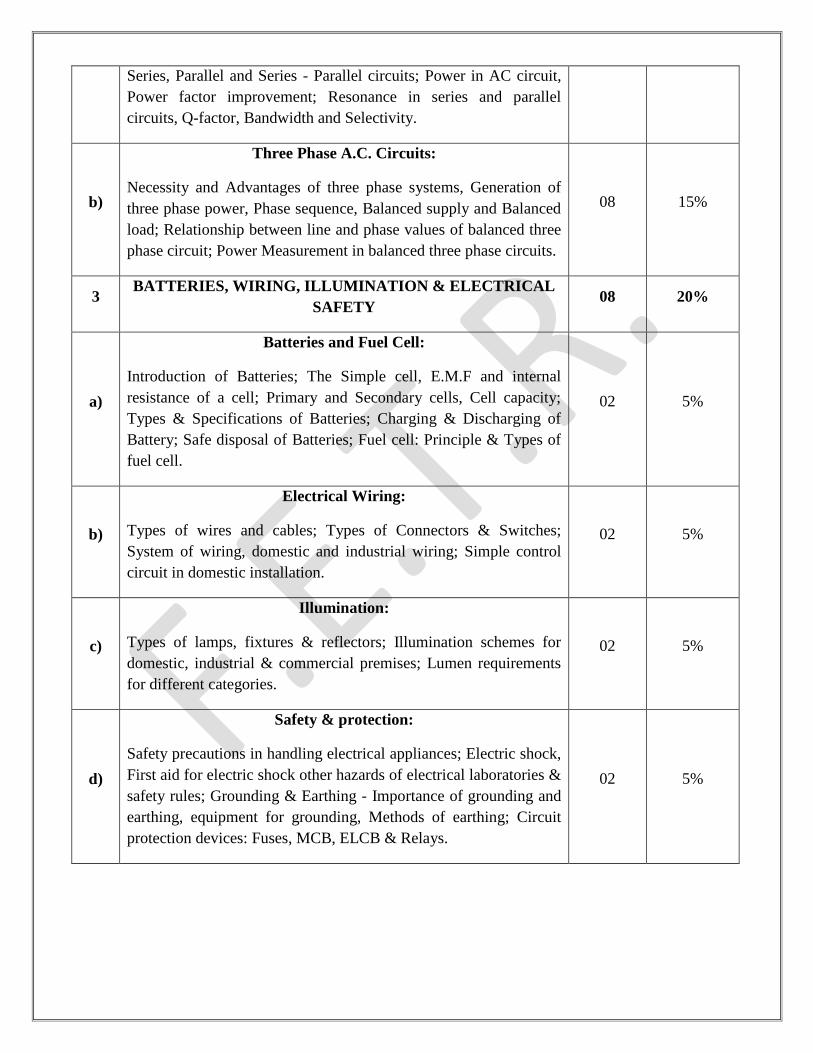
Series, Parallel and Series - Parallel circuits; Power in AC circuit,
Power factor improvement; Resonance in series and parallel
circuits, Q-factor, Bandwidth and Selectivity.
b)
Three Phase A.C. Circuits:
Necessity and Advantages of three phase systems, Generation of
three phase power, Phase sequence, Balanced supply and Balanced
load; Relationship between line and phase values of balanced three
phase circuit; Power Measurement in balanced three phase circuits.
08 15%
3 BATTERIES, WIRING, ILLUMINATION & ELECTRICAL
SAFETY 08 20%
a)
Batteries and Fuel Cell:
Introduction of Batteries; The Simple cell, E.M.F and internal
resistance of a cell; Primary and Secondary cells, Cell capacity;
Types & Specifications of Batteries; Charging & Discharging of
Battery; Safe disposal of Batteries; Fuel cell: Principle & Types of
fuel cell.
02 5%
b)
Electrical Wiring:
Types of wires and cables; Types of Connectors & Switches;
System of wiring, domestic and industrial wiring; Simple control
circuit in domestic installation.
02 5%
c)
Illumination:
Types of lamps, fixtures & reflectors; Illumination schemes for
domestic, industrial & commercial premises; Lumen requirements
for different categories.
02 5%
d)
Safety & protection:
Safety precautions in handling electrical appliances; Electric shock,
First aid for electric shock other hazards of electrical laboratories &
safety rules; Grounding & Earthing - Importance of grounding and
earthing, equipment for grounding, Methods of earthing; Circuit
protection devices: Fuses, MCB, ELCB & Relays.
02 5%
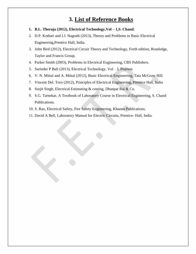
3. List of Reference Books
1. B.L. Theraja (2012), Electrical Technology,Vol – 1,S. Chand.
2. D.P. Kothari and I.J. Nagrath (2013), Theory and Problems in Basic Electrical
Engineering,Prentice Hall, India.
3. John Bird (2012), Electrical Circuit Theory and Technology, Forth edition, Routledge,
Taylor and Francis Group.
4. Parker Smith (2003), Problems in Electrical Engineering, CBS Publishers.
5. Surinder P Bali (2013), Electrical Technology, Vol – I, Pearson
6. V. N. Mittal and A. Mittal (2012), Basic Electrical Engineering, Tata McGraw Hill.
7. Vincent Del. Toro (2012), Principles of Electrical Engineering, Prentice Hall, India
8. Surjit Singh, Electrical Estimating & costing, Dhanpat Rai & Co.
9. S.G. Tarnekar, A Textbook of Laboratory Course in Electrical Engineering, S. Chand
Publications.
10. S. Rao, Electrical Safety, Fire Safety Engineering, Khanna Publications.
11. David A Bell, Laboratory Manual for Electric Circuits, Prentice‐ Hall, India.

4. List of Experiments
Sr.
No. Name of Experiments
1 To Study & Understand Different Symbols Used In Electrical Circuits.
2 To Know Various Electrical Equipment‟s & Instruments And Their Operations.
3 To Verify The OHM‟s Law.
4 To Verify The Laws Of Resistance Connected In Series and Parallel.
5 To Verify The Effect Of Temperature On Resistance And Determine The Temperature Co-
Efficient Of Resistance.
6 Verification Of Kirchhoff‟s Current & Kirchhoff‟s Voltage Law.
7 To Establish Star Connection Of Resistance & To Convert It Into Equivalent Delta
Connection & Vice Versa.
8 To Verify The Effect Of Power Factor And Power By Varying Value Of Resistance,
Inductance & Capacitance Connected In Series.
9 To Verify The Phase And Line Relation Of Voltage And Currents In Three Phase Star &
Delta Connection.
10 To Plot The Magnetizing Characteristics & Study The Hysteresis Loop For A Magnetic
Material On CRO.
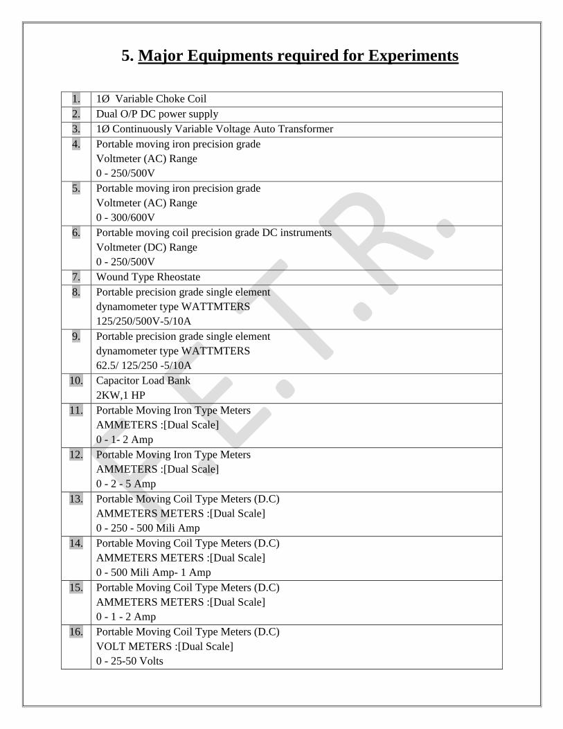
5. Major Equipments required for Experiments
1. 1Ø Variable Choke Coil
2. Dual O/P DC power supply
3. 1Ø Continuously Variable Voltage Auto Transformer
4. Portable moving iron precision grade
Voltmeter (AC) Range
0 - 250/500V
5. Portable moving iron precision grade
Voltmeter (AC) Range
0 - 300/600V
6. Portable moving coil precision grade DC instruments
Voltmeter (DC) Range
0 - 250/500V
7. Wound Type Rheostate
8. Portable precision grade single element
dynamometer type WATTMTERS
125/250/500V-5/10A
9. Portable precision grade single element
dynamometer type WATTMTERS
62.5/ 125/250 -5/10A
10. Capacitor Load Bank
2KW,1 HP
11. Portable Moving Iron Type Meters
AMMETERS :[Dual Scale]
0 - 1- 2 Amp
12. Portable Moving Iron Type Meters
AMMETERS :[Dual Scale]
0 - 2 - 5 Amp
13. Portable Moving Coil Type Meters (D.C)
AMMETERS METERS :[Dual Scale]
0 - 250 - 500 Mili Amp
14. Portable Moving Coil Type Meters (D.C)
AMMETERS METERS :[Dual Scale]
0 - 500 Mili Amp- 1 Amp
15. Portable Moving Coil Type Meters (D.C)
AMMETERS METERS :[Dual Scale]
0 - 1 - 2 Amp
16. Portable Moving Coil Type Meters (D.C)
VOLT METERS :[Dual Scale]
0 - 25-50 Volts
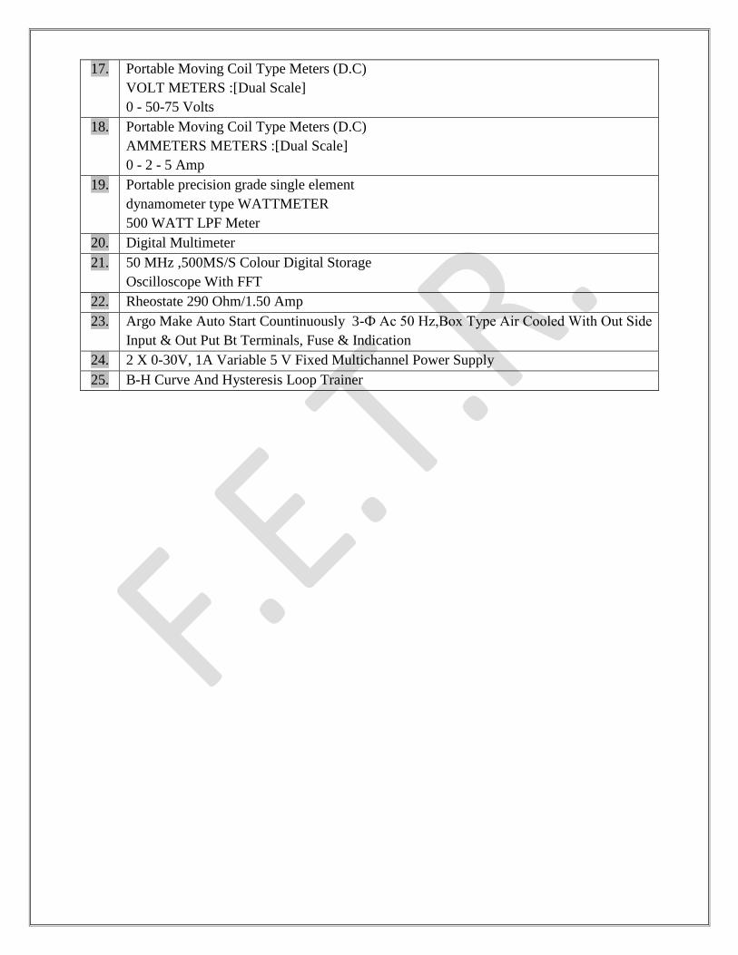
17. Portable Moving Coil Type Meters (D.C)
VOLT METERS :[Dual Scale]
0 - 50-75 Volts
18. Portable Moving Coil Type Meters (D.C)
AMMETERS METERS :[Dual Scale]
0 - 2 - 5 Amp
19. Portable precision grade single element
dynamometer type WATTMETER
500 WATT LPF Meter
20. Digital Multimeter
21. 50 MHz ,500MS/S Colour Digital Storage
Oscilloscope With FFT
22. Rheostate 290 Ohm/1.50 Amp
23. Argo Make Auto Start Countinuously 3-Ф Ac 50 Hz,Box Type Air Cooled With Out Side
Input & Out Put Bt Terminals, Fuse & Indication
24. 2 X 0-30V, 1A Variable 5 V Fixed Multichannel Power Supply
25. B-H Curve And Hysteresis Loop Trainer
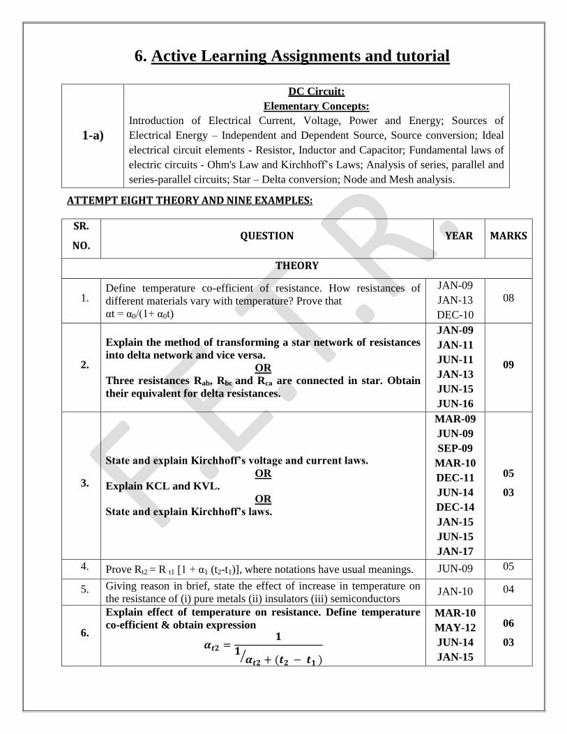
6. Active Learning Assignments and tutorial
1-a)
DC Circuit:
Elementary Concepts:
Introduction of Electrical Current, Voltage, Power and Energy; Sources of
Electrical Energy – Independent and Dependent Source, Source conversion; Ideal
electrical circuit elements - Resistor, Inductor and Capacitor; Fundamental laws of
electric circuits - Ohm's Law and Kirchhoff‟s Laws; Analysis of series, parallel and
series-parallel circuits; Star – Delta conversion; Node and Mesh analysis.
ATTEMPT EIGHT THEORY AND NINE EXAMPLES:
SR.
NO. QUESTION YEAR MARKS
THEORY
1. Define temperature co-efficient of resistance. How resistances of
different materials vary with temperature? Prove that
αt = α0/(1+ α0t)
JAN-09
JAN-13
DEC-10
08
2.
Explain the method of transforming a star network of resistances
into delta network and vice versa.
OR
Three resistances Rab, Rbc and Rca are connected in star. Obtain
their equivalent for delta resistances.
JAN-09
JAN-11
JUN-11
JAN-13
JUN-15
JUN-16
09
3.
State and explain Kirchhoff’s voltage and current laws.
OR
Explain KCL and KVL.
OR
State and explain Kirchhoff’s laws.
MAR-09
JUN-09
SEP-09
MAR-10
DEC-11
JUN-14
DEC-14
JAN-15
JUN-15
JAN-17
05
03
4. Prove Rt2 = R t1 [1 + α1 (t2-t1)], where notations have usual meanings. JUN-09 05
5. Giving reason in brief, state the effect of increase in temperature on
the resistance of (i) pure metals (ii) insulators (iii) semiconductors JAN-10 04
6.
Explain effect of temperature on resistance. Define temperature
co-efficient & obtain expression
𝜶𝒕𝟐 =𝟏
𝟏𝜶𝒕𝟐 + (𝒕𝟐 − 𝒕𝟏 )
MAR-10
MAY-12
JUN-14
JAN-15
06
03
JAN-15
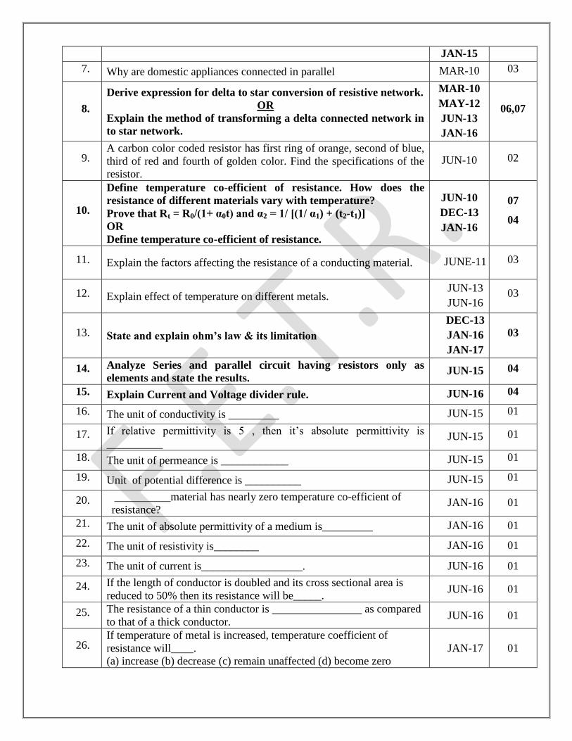
7. Why are domestic appliances connected in parallel MAR-10 03
8.
Derive expression for delta to star conversion of resistive network.
OR
Explain the method of transforming a delta connected network in
to star network.
MAR-10
MAY-12
JUN-13
JAN-16
06,07
9. A carbon color coded resistor has first ring of orange, second of blue,
third of red and fourth of golden color. Find the specifications of the
resistor.
JUN-10 02
10.
Define temperature co-efficient of resistance. How does the
resistance of different materials vary with temperature?
Prove that Rt = R0/(1+ α0t) and α2 = 1/ [(1/ α1) + (t2-t1)]
OR
Define temperature co-efficient of resistance.
JUN-10
DEC-13
JAN-16
07
04
11. Explain the factors affecting the resistance of a conducting material. JUNE-11 03
12. Explain effect of temperature on different metals. JUN-13
JUN-16 03
13. State and explain ohm’s law & its limitation
DEC-13
JAN-16
JAN-17
03
14. Analyze Series and parallel circuit having resistors only as
elements and state the results. JUN-15 04
15. Explain Current and Voltage divider rule. JUN-16 04
16. The unit of conductivity is _________ JUN-15 01
17. If relative permittivity is 5 , then it‟s absolute permittivity is
__________ JUN-15 01
18. The unit of permeance is ____________ JUN-15 01
19. Unit of potential difference is __________ JUN-15 01
20. __________material has nearly zero temperature co-efficient of
resistance?
JAN-16 01
21. The unit of absolute permittivity of a medium is_________ JAN-16 01
22. The unit of resistivity is________ JAN-16 01
23. The unit of current is__________________. JUN-16 01
24. If the length of conductor is doubled and its cross sectional area is
reduced to 50% then its resistance will be_____. JUN-16 01
25. The resistance of a thin conductor is ________________ as compared
to that of a thick conductor. JUN-16 01
26. If temperature of metal is increased, temperature coefficient of
resistance will____.
(a) increase (b) decrease (c) remain unaffected (d) become zero
JAN-17 01
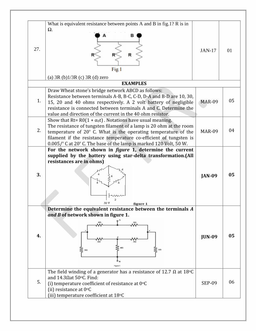
27.
What is equivalent resistance between points A and B in fig.1? R is in
Ω.
(a) 3R (b)1/3R (c) 3R (d) zero
JAN-17 01
EXAMPLES
1.
Draw Wheat stone’s bridge network ABCD as follows: Resistance between terminals A-B, B-C, C-D, D-A and B-D are 10, 30, 15, 20 and 40 ohms respectively. A 2 volt battery of negligible resistance is connected between terminals A and C. Determine the value and direction of the current in the 40 ohm resistor.
MAR-09 05
2.
Show that Rt= R0(1 + α0t) . Notations have usual meaning. The resistance of tungsten filament of a lamp is 20 ohm at the room temperature of 20º C. What is the operating temperature of the filament if the resistance temperature co-efficient of tungsten is 0.005/º C at 20º C. The base of the lamp is marked 120 Volt, 50 W.
MAR-09 04
3.
For the network shown in figure 1, determine the current supplied by the battery using star-delta transformation.(All resistances are in ohms)
JAN-09 05
4.
Determine the equivalent resistance between the terminals A and B of network shown in figure 1.
JUN-09 05
5.
The field winding of a generator has a resistance of 12.7 Ω at 18oC and 14.3Ωat 50oC. Find: (i) temperature coefficient of resistance at 0oC (ii) resistance at 0oC (iii) temperature coefficient at 18oC
SEP-09 06
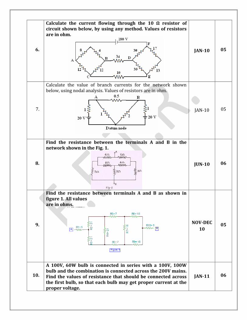
6.
Calculate the current flowing through the 10 Ω resistor of circuit shown below, by using any method. Values of resistors are in ohm.
JAN-10 05
7.
Calculate the value of branch currents for the network shown below, using nodal analysis. Values of resistors are in ohm.
JAN-10 05
8.
Find the resistance between the terminals A and B in the network shown in the Fig. 1.
JUN-10 06
9.
Find the resistance between terminals A and B as shown in figure 1. All values are in ohms.
NOV-DEC
10 05
10.
A 100V, 60W bulb is connected in series with a 100V, 100W bulb and the combination is connected across the 200V mains. Find the values of resistance that should be connected across the first bulb, so that each bulb may get proper current at the proper voltage.
JAN-11 06
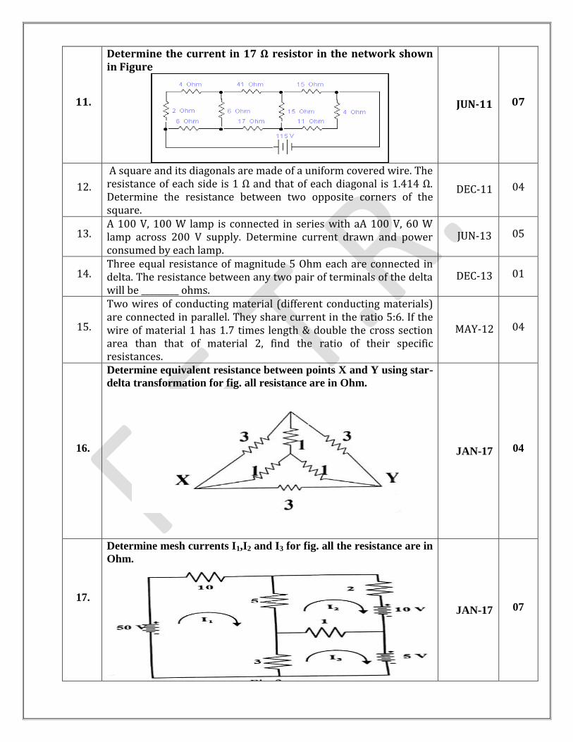
11.
Determine the current in 17 Ω resistor in the network shown in Figure
JUN-11 07
12.
A square and its diagonals are made of a uniform covered wire. The resistance of each side is 1 Ω and that of each diagonal is 1.414 Ω. Determine the resistance between two opposite corners of the square.
DEC-11 04
13. A 100 V, 100 W lamp is connected in series with aA 100 V, 60 W lamp across 200 V supply. Determine current drawn and power consumed by each lamp.
JUN-13 05
14. Three equal resistance of magnitude 5 Ohm each are connected in delta. The resistance between any two pair of terminals of the delta will be _________ ohms.
DEC-13 01
15.
Two wires of conducting material (different conducting materials) are connected in parallel. They share current in the ratio 5:6. If the wire of material 1 has 1.7 times length & double the cross section area than that of material 2, find the ratio of their specific resistances.
MAY-12 04
16.
Determine equivalent resistance between points X and Y using star-
delta transformation for fig. all resistance are in Ohm.
JAN-17 04
17. t
i
Determine mesh currents I1,I2 and I3 for fig. all the resistance are in
Ohm.
JAN-17 07
1-b)
Electrostatics:
Electric charge and Laws of electrostatics; Definitions - Electric field, lines of force,
electric field intensity, electric flux and flux density; Electrostatic induction; Gauss‟s
law and its application; Dielectric strength; Capacitor; Capacitor in series and parallel,
Energy stored in a capacitor.
ATTEMPT FIVE THEORY AND TEN EXAMPLES:
SR.
NO. QUESTION YEAR MARKS
THEORY
1.
Derive the expression for the voltage across the capacitor at any
instant after the application of dc voltage V to a circuit having a
capacitance C in series with resistance R.
JAN-09 07
2.
Derive an expression for the capacitance of a parallel plate capacitor
with plate area „A‟ and distance of separation between the plates „d‟
in M.K.S.
OR
Derive an expression of capacitance for parallel plate type
construction of capacitor with usual notations.
MAR-09
JAN-13
JAN-17
07
03
3. Distinguish statically induced and dynamically induced EMF. Derive
expression for dynamically induced EMF. JUN-09 05
4.
With reference to electrostatic and capacitance: (i) State
Coulomb’s laws (ii) Define:- (a) electric field intensity (b) electric
potential (c) potential gradient (d) permittivity (e) capacitance
JAN-10
DEC-11
MAY-12
07
5. Describe “Ceramic Capacitors”. JUN-10 03
6. Discuss the forces acting between two parallel current carrying
conductors. JUN-10 06
7. Explain different types of capacitors in brief. NOV-10 04
8. State coulomb’s law of electrostatics.
JAN-11
JAN-15
JUN-15
02
9.
Explain charging and discharging of a capacitor, C, through a
resistor, R, with neat sketch and derive the equation Vc = V (1- e-
t/RC). Assume that the R-C series circuit is connected across a d.c
supply of voltage V.
DEC-10
JUN-11 07
10. Derive expression for voltage across capacitor (vc) during charging of
capacitor JUN-13 06
11.
Analyze the series and parallel connection of capacitor and prove
the equations. Also find out the equation for energy stored in
capacitor.
JUN-09
SEP-09
JAN-11
07
04
OR
Analyze the series and parallel connection of capacitor.
DEC-11
JUN-14
JAN-15
JUN-15
JAN-15
JAN-16
12. Find out the equation for energy stored in capacitor JAN-15
JAN-16 03
13. Derive the expression for the equivalent capacitance of capacitors
connected in parallel.
JUN-16
03
14. Coulomb‟s second law is called as ________________law. JUN-16
01
15. State principle electrostatic induction. JAN-17 01
EXAMPLES
1.
Two capacitors having 8 μF and 4 μF are connected in series and
charged from a constant voltage of 210 Volts supply. Calculate (a)
The voltage across each capacitor (b) The charge on each
capacitor.
MAR-09 07
2.
A capacitor of 10 μF is connected to a DC supply through a resistance
of 1.1 MΩ. Calculate the time taken for the capacitor to reach 90 % of
its final charge.
MAR-09 07
3.
A 10 μF capacitor is connected in series with a 1MΩ resistor. This
combination is connected across a 100V D.C. supply determine
(i)time constant of the circuit (ii) the initial value of the charging
current (iii) the initial rate of rise of voltage across the capacitor (iv)
time taken for the capacitor voltage to reach 60 V.
JUN-09 07
4.
A 2 μF capacitor is connected by closing a switch to a supply of
100 volts through 1 MΩ series resistance. Calculate:
(i) Time constant (ii) initial charging current (iii) the initial rate
of rise of voltage across capacitor (iv) voltage across the capacitor
6 seconds after the switch has been closed.
SEP-09
07
5.
Three capacitors have capacitance of 10, 50 and 25 μF.
Calculate: (i) charge on each capacitor when they are connected in
parallel to a 250 V supply (ii) total capacitance and (iii) potential
difference across each capacitor when they are connected in series.
JAN-10 07
6.
A resistor of 2 MΩ is connected in series with a capacitor of 0.01
μF across d.c. voltage source of 50 V. Calculate:
(a) Capacitor voltage after 0.02 sec, 0.04 sec, 0.06 sec and 1 hour.
(b) Charging current after 0.02 sec, 0.04 sec, 0.06 sec and 0.1 sec.
JAN-10 07
7. A parallel plate capacitor has a plate area of 4 cm
2.The plates are
separated by Three slabs of different dielectric materials of
MAR-10
JAN-13 08
thicknesses 0.3, 0.4 , & 0.3 mm With relative permittivity of 3, 2.5
and 2 respectively. Calculate the capacitance of each material and
the voltage across them if the supply is 200 V
8.
Two square conducting plates having a cross sectional area of 2500
cm2 and 1 cm distance between them are connected across a 600 V
supply voltage. They have a dielectric, 0.8 cm thick having a relative
permittivity of 4 between them. The remaining space is filled with air.
Calculate the capacitance of the condenser and the energy stored in it.
JUN-10 07
9.
Two capacitors C1= 4μF and C2= 2 μF are connected in parallel
across a 200V DC supply find (1) Equivalent capacitance (2) charge
across each capacitor (3) If this parallel capacitor combination
connected in series with 6μF then what would be the equivalent
capacitance of circuit becomes?
NOV-10 07
10.
A series combination having R = 2 MΩ and C = 0.01 μF is connected
across d.c. voltage source of 50V. Determine capacitor voltage and
charging current after 0.02 s, 0.04 s and 0.06 s.
JAN-11 06
11.
A parallel plate capacitor has plates of area 2 cm2 spaced by three
slabs of different materials .The relative permittivity are 2,3 and
6 and thickness are 0.4, 0.6 and 1.2 mm respectively. Calculate
the equivalent capacitance and electric stress in each material
when the applied voltage is 1000 V.
JUN-11 07
12.
A parallel plate capacitor with five plates has each plate one meter
square area at a distance of 1.5 mm and a dielectric of relative
permittivity 3.5. If the capacitor is charged to 1000 volt, how much
energy will be stored in it.
DEC-11 07
13.
In the RC circuit shown in the Fig. 2, R= 2 MΩ and C= 5μF. The
capacitor is charged to an initial potential of 50 V, when the
switch is closed at t=0+.
Calculate 1. Initial rate of charging of the capacitor voltage.
2. Capacitor voltage after time = 5λ seconds.
If the polarity of the capacitor voltage is reversed, calculate,
3. The values of the above quantities.
4. Time taken for Vc to reach -10 V, 0V and 95 V.
JUN-10 07
14.
The equivalent capacitance of two capacitors when connected in
series is 0.03 μF & when connected in parallel is 0.16 μF. Find the
capacitance of the both the capacitors.
MAY-12 04
15.
Capacitor of 50 μF in series with 100 Ohm resistor with suddenly
connected across 100 volts DC supply. Find (1) Time constant of the
circuit (2) Initial Current (3) Current Equation as a function of time
(4) Voltage across resistor after6 m.sec.
MAY-12 07
16.
Three capacitors having capacitances of 10 μF, 20 μF and 40 μF
are connected in series to a 400 V d.c. source. Find (i) total
capacitance (ii) total charge in circuit (iii) total energy stored.
JUN-13
DEC-13
JUN-14
04
17. The five 0.050uF capacitors are connected in parallel. The equivalent
capacitance is ____________. DEC-13 01
18.
A capacitor of 0.1µF is charged from a 100V battery through a
series resistance of 1000Ω. Find
[1]Time constant
[2]Charge received during this time
[3]Initial rate of charging
[4]The rate of charging when the charge is 63.2% of final
charge.
JUN-15 04
19.
The equivalent capacitance of two capacitors when connected in
series is 0.03 μF & when connected in parallel is 0.16 μF. Find the
capacitance of both the capacitors.
JUN-16 04
20.
Three capacitors having capacitances of 10 μF, 20 μF and 40 μF
are connected in series to a 400 V d.c. source. Find (i) Total
capacitance (ii) Total charge in circuit (iii) Total energy stored.
JUN-16 07
21.
Two capacitors of capacitances 8 μF and 2 μF are connected in series
across 100 V DC supply. Now if the supply is removed and the
capacitors are connected in parallel, what will be the final charge on
each capacitor?
JAN-17 07
1-c)
Electromagnetism:
Faradays Laws; Lenz's Law; Fleming's Rules; Effect of magnetic field on
current carrying conductor; Magnetic circuits; Statically and dynamically
induced EMF; Concepts of self-inductance, mutual inductance and coefficient of
coupling; Inductance in series and parallel; Hysteresis and Eddy current losses;
Energy stored in magnetic fields.
ATTEMPT SEVEN THEORY AND EIGHT EXAMPLES:
SR.
NO. QUESTION YEAR MARKS
THEORY
1.
Give the comparison between electric and magnetic
circuit.
OR
Compare Electric and Magnetic circuit.
OR
Analyze magnetic and electric circuits by similarities and
differences.
OR
State similarities between magnetic circuit and electrical
circuit.
MAR-09
JUN-09
SEP-09
JAN10
JUN-10
NOV-10
JAN-11
JAN-13
JUN-13
JAN-15
JUN-15
JAN-16
JUN-16
05
04
2. State and explain Faraday’s laws of electromagnetic
induction.
MAR-09
JUN-09
MAR-10
DEC-11
JUN-14
JAN-15
JUN-15
JAN-16
JAN-17
04
3. (i) Explain Magnetic Hysteresis. (ii) What do you understand
by coefficient of coupling between two magnetic coils? JUN-09 04
4. Derive the expressions of equivalent inductance, when two
Magnetically coupled coils are connected in series in two
different ways.
JUN-09
JUN-10 05
5. Explain the term (i) reluctance (ii) permeability. JUN-09 04
6. What is coefficient of coupling? Derive the relation
between self and mutual inductance.
SEP-09
JUN-11
JUN-14
08
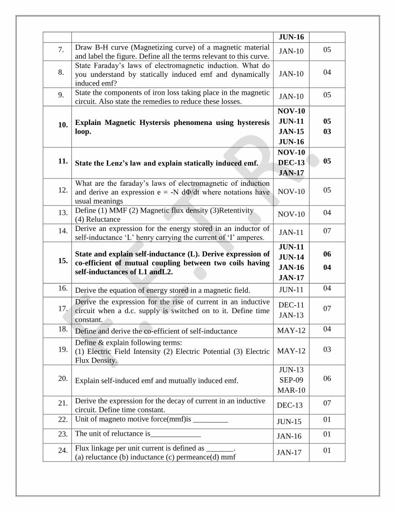
JUN-16
7. Draw B-H curve (Magnetizing curve) of a magnetic material
and label the figure. Define all the terms relevant to this curve. JAN-10 05
8. State Faraday‟s laws of electromagnetic induction. What do
you understand by statically induced emf and dynamically
induced emf?
JAN-10 04
9. State the components of iron loss taking place in the magnetic
circuit. Also state the remedies to reduce these losses. JAN-10 05
10. Explain Magnetic Hystersis phenomena using hysteresis
loop.
NOV-10
JUN-11
JAN-15
JUN-16
05
03
11. State the Lenz’s law and explain statically induced emf.
NOV-10
DEC-13
JAN-17
05
12. What are the faraday‟s laws of electromagnetic of induction
and derive an expression e = -N dΦ/dt where notations have
usual meanings
NOV-10 05
13. Define (1) MMF (2) Magnetic flux density (3)Retentivity
(4) Reluctance NOV-10 04
14. Derive an expression for the energy stored in an inductor of
self-inductance „L‟ henry carrying the current of „I‟ amperes. JAN-11 07
15. State and explain self-inductance (L). Derive expression of
co-efficient of mutual coupling between two coils having
self-inductances of L1 andL2.
JUN-11
JUN-14
JAN-16
JAN-17
06
04
16. Derive the equation of energy stored in a magnetic field. JUN-11 04
17. Derive the expression for the rise of current in an inductive
circuit when a d.c. supply is switched on to it. Define time
constant.
DEC-11
JAN-13 07
18. Define and derive the co-efficient of self-inductance MAY-12 04
19. Define & explain following terms:
(1) Electric Field Intensity (2) Electric Potential (3) Electric
Flux Density.
MAY-12 03
20. Explain self-induced emf and mutually induced emf.
JUN-13
SEP-09
MAR-10
06
21. Derive the expression for the decay of current in an inductive
circuit. Define time constant. DEC-13 07
22. Unit of magneto motive force(mmf)is _________ JUN-15 01
23. The unit of reluctance is_____________ JAN-16 01
24. Flux linkage per unit current is defined as _______.
(a) reluctance (b) inductance (c) permeance(d) mmf JAN-17 01
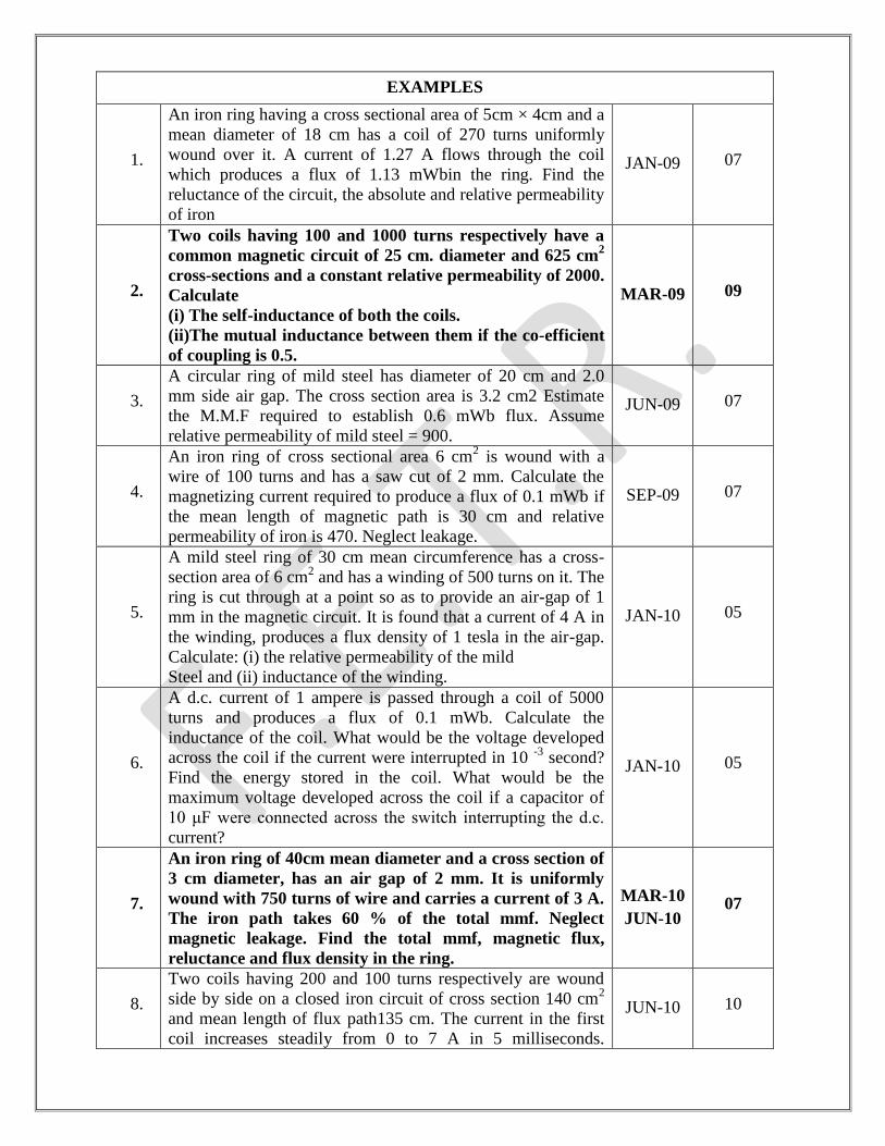
EXAMPLES
1.
An iron ring having a cross sectional area of 5cm × 4cm and a
mean diameter of 18 cm has a coil of 270 turns uniformly
wound over it. A current of 1.27 A flows through the coil
which produces a flux of 1.13 mWbin the ring. Find the
reluctance of the circuit, the absolute and relative permeability
of iron
JAN-09 07
2.
Two coils having 100 and 1000 turns respectively have a
common magnetic circuit of 25 cm. diameter and 625 cm2
cross-sections and a constant relative permeability of 2000.
Calculate
(i) The self-inductance of both the coils.
(ii)The mutual inductance between them if the co-efficient
of coupling is 0.5.
MAR-09 09
3.
A circular ring of mild steel has diameter of 20 cm and 2.0
mm side air gap. The cross section area is 3.2 cm2 Estimate
the M.M.F required to establish 0.6 mWb flux. Assume
relative permeability of mild steel = 900.
JUN-09 07
4.
An iron ring of cross sectional area 6 cm2 is wound with a
wire of 100 turns and has a saw cut of 2 mm. Calculate the
magnetizing current required to produce a flux of 0.1 mWb if
the mean length of magnetic path is 30 cm and relative
permeability of iron is 470. Neglect leakage.
SEP-09 07
5.
A mild steel ring of 30 cm mean circumference has a cross-
section area of 6 cm2 and has a winding of 500 turns on it. The
ring is cut through at a point so as to provide an air-gap of 1
mm in the magnetic circuit. It is found that a current of 4 A in
the winding, produces a flux density of 1 tesla in the air-gap.
Calculate: (i) the relative permeability of the mild
Steel and (ii) inductance of the winding.
JAN-10 05
6.
A d.c. current of 1 ampere is passed through a coil of 5000
turns and produces a flux of 0.1 mWb. Calculate the
inductance of the coil. What would be the voltage developed
across the coil if the current were interrupted in 10 -3
second?
Find the energy stored in the coil. What would be the
maximum voltage developed across the coil if a capacitor of
10 μF were connected across the switch interrupting the d.c.
current?
JAN-10 05
7.
An iron ring of 40cm mean diameter and a cross section of
3 cm diameter, has an air gap of 2 mm. It is uniformly
wound with 750 turns of wire and carries a current of 3 A.
The iron path takes 60 % of the total mmf. Neglect
magnetic leakage. Find the total mmf, magnetic flux,
reluctance and flux density in the ring.
MAR-10
JUN-10 07
8.
Two coils having 200 and 100 turns respectively are wound
side by side on a closed iron circuit of cross section 140 cm2
and mean length of flux path135 cm. The current in the first
coil increases steadily from 0 to 7 A in 5 milliseconds.
JUN-10 10
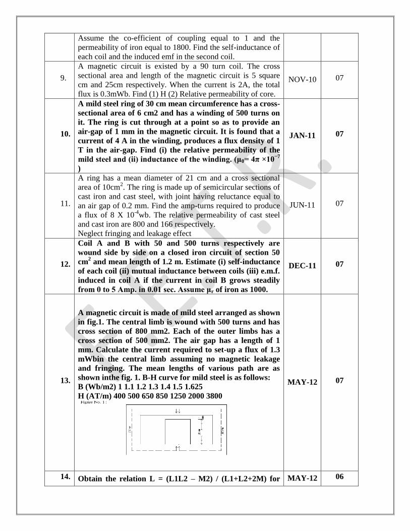
Assume the co-efficient of coupling equal to 1 and the
permeability of iron equal to 1800. Find the self-inductance of
each coil and the induced emf in the second coil.
9.
A magnetic circuit is existed by a 90 turn coil. The cross
sectional area and length of the magnetic circuit is 5 square
cm and 25cm respectively. When the current is 2A, the total
flux is 0.3mWb. Find (1) H (2) Relative permeability of core.
NOV-10 07
10.
A mild steel ring of 30 cm mean circumference has a cross-
sectional area of 6 cm2 and has a winding of 500 turns on
it. The ring is cut through at a point so as to provide an
air-gap of 1 mm in the magnetic circuit. It is found that a
current of 4 A in the winding, produces a flux density of 1
T in the air-gap. Find (i) the relative permeability of the
mild steel and (ii) inductance of the winding. (μ0= 4π ×10−7
)
JAN-11 07
11.
A ring has a mean diameter of 21 cm and a cross sectional
area of 10cm2. The ring is made up of semicircular sections of
cast iron and cast steel, with joint having reluctance equal to
an air gap of 0.2 mm. Find the amp-turns required to produce
a flux of 8 X 10⁻⁴
wb. The relative permeability of cast steel
and cast iron are 800 and 166 respectively.
Neglect fringing and leakage effect
JUN-11 07
12.
Coil A and B with 50 and 500 turns respectively are
wound side by side on a closed iron circuit of section 50
cm2 and mean length of 1.2 m. Estimate (i) self-inductance
of each coil (ii) mutual inductance between coils (iii) e.m.f.
induced in coil A if the current in coil B grows steadily
from 0 to 5 Amp. in 0.01 sec. Assume μr of iron as 1000.
DEC-11 07
13.
A magnetic circuit is made of mild steel arranged as shown
in fig.1. The central limb is wound with 500 turns and has
cross section of 800 mm2. Each of the outer limbs has a
cross section of 500 mm2. The air gap has a length of 1
mm. Calculate the current required to set-up a flux of 1.3
mWbin the central limb assuming no magnetic leakage
and fringing. The mean lengths of various path are as
shown inthe fig. 1. B-H curve for mild steel is as follows:
B (Wb/m2) 1 1.1 1.2 1.3 1.4 1.5 1.625
H (AT/m) 400 500 650 850 1250 2000 3800
MAY-12 07
14. Obtain the relation L = (L1L2 – M2) / (L1+L2+2M) for MAY-12 06
equivalent inductance when two inductors are connected
in parallel such that the mutually induced emf opposes the
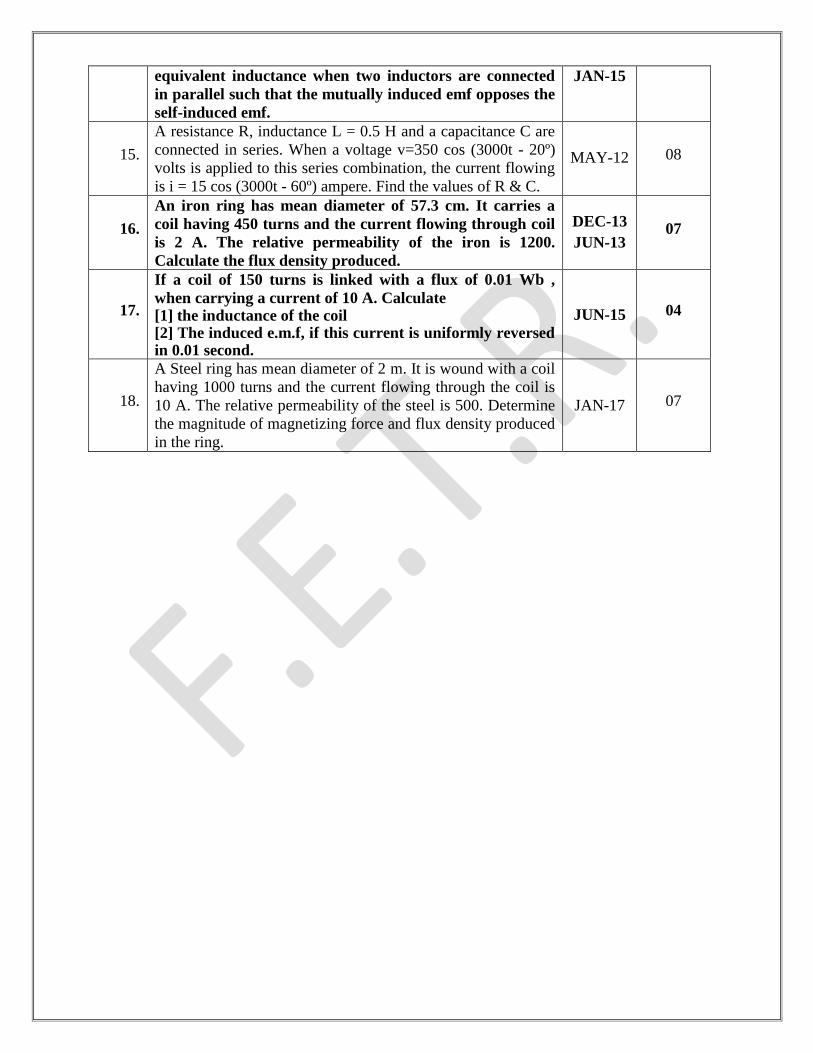
self-induced emf.
JAN-15
15.
A resistance R, inductance L = 0.5 H and a capacitance C are
connected in series. When a voltage v=350 cos (3000t - 20º)
volts is applied to this series combination, the current flowing
is i = 15 cos (3000t - 60º) ampere. Find the values of R & C.
MAY-12 08
16.
An iron ring has mean diameter of 57.3 cm. It carries a
coil having 450 turns and the current flowing through coil
is 2 A. The relative permeability of the iron is 1200.
Calculate the flux density produced.
DEC-13
JUN-13 07
17.
If a coil of 150 turns is linked with a flux of 0.01 Wb ,
when carrying a current of 10 A. Calculate [1] the inductance of the coil [2] The induced e.m.f, if this current is uniformly reversed in 0.01 second.
JUN-15 04
18.
A Steel ring has mean diameter of 2 m. It is wound with a coil
having 1000 turns and the current flowing through the coil is
10 A. The relative permeability of the steel is 500. Determine
the magnitude of magnetizing force and flux density produced
in the ring.
JAN-17 07
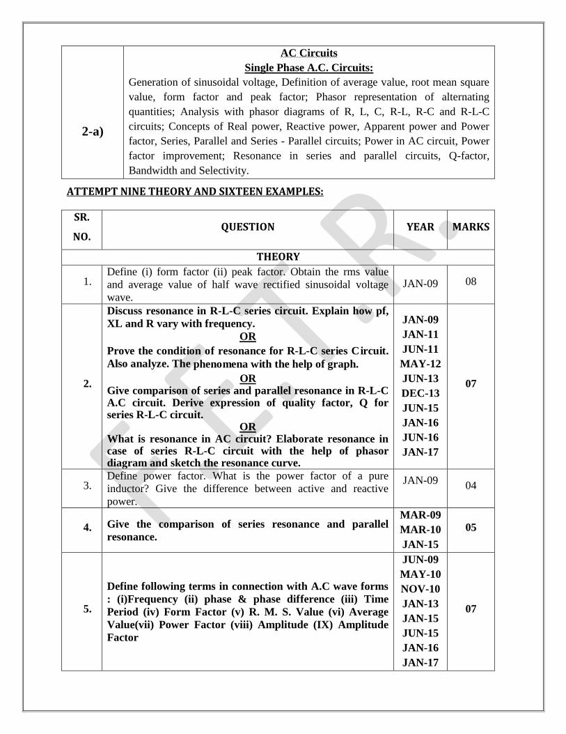
2-a)
AC Circuits
Single Phase A.C. Circuits:
Generation of sinusoidal voltage, Definition of average value, root mean square
value, form factor and peak factor; Phasor representation of alternating
quantities; Analysis with phasor diagrams of R, L, C, R-L, R-C and R-L-C
circuits; Concepts of Real power, Reactive power, Apparent power and Power
factor, Series, Parallel and Series - Parallel circuits; Power in AC circuit, Power
factor improvement; Resonance in series and parallel circuits, Q-factor,
Bandwidth and Selectivity.
ATTEMPT NINE THEORY AND SIXTEEN EXAMPLES:
SR.
NO. QUESTION YEAR MARKS
THEORY
1. Define (i) form factor (ii) peak factor. Obtain the rms value
and average value of half wave rectified sinusoidal voltage
wave.
JAN-09 08
2.
Discuss resonance in R-L-C series circuit. Explain how pf,
XL and R vary with frequency.
OR
Prove the condition of resonance for R-L-C series Circuit.
Also analyze. The phenomena with the help of graph.
OR Give comparison of series and parallel resonance in R-L-C A.C circuit. Derive expression of quality factor, Q for series R-L-C circuit.
OR What is resonance in AC circuit? Elaborate resonance in case of series R-L-C circuit with the help of phasor diagram and sketch the resonance curve.
JAN-09
JAN-11
JUN-11
MAY-12
JUN-13
DEC-13
JUN-15
JAN-16
JUN-16
JAN-17
07
3. Define power factor. What is the power factor of a pure
inductor? Give the difference between active and reactive
power.
JAN-09
04
4. Give the comparison of series resonance and parallel
resonance.
MAR-09
MAR-10
JAN-15
05
5.
Define following terms in connection with A.C wave forms
: (i)Frequency (ii) phase & phase difference (iii) Time
Period (iv) Form Factor (v) R. M. S. Value (vi) Average
Value(vii) Power Factor (viii) Amplitude (IX) Amplitude
Factor
JUN-09
MAY-10
NOV-10
JAN-13
JAN-15
JUN-15
JAN-16
JAN-17
07
6. Define the term (1) reactance, (2) inductive reactance and (3)
capacitive reactance and explain how it depends on frequency
in an A.C. Circuit.
JUN-09
07
7.
Prove that in a purely capacitive circuit power consumed is
zero when a.c. voltage is applied. Draw relevant phasor
diagram and waveforms.
SEP-09
JUN-11
DEC-13
08
8. An inductive coil of resistance R and inductance L is
connected in parallel with a capacitor of C. Derive an
expression for resonant frequency and Q factor.
SEP-09
JAN-10
DEC-11
DEC-13
08
9. Define following terms with respect to a.c. Waveform(i)
Frequency (ii) Power factor (iii) R.M.S. value (iv)
Amplitude (v) Average value (vi) Form Factor.
MAR-10 06
10. Prove that current through pure inductor is always lagging by
90o to its voltage and power consumed is zero.
MAR-10
JUN-13 07
11. Discuss different methods of representation of vector
quantities. JUN-10 03
12. Discuss how the inductance of a choke coil can be measured
using a rheostat, a voltmeter and an ammeter. JUN-10 04
13. Derive the equation of power in a single phase AC circuit in
vector form only. JUN-10 02
14. Explain the phenomena of generation of Alternating
voltages and currents and derive expression for it with
suitable diagrams
NOV-10
JUN-14
JAN-15
06
15. Distinguish between (i) apparent power (ii) active power and
(iii) reactive power. JAN-11 03
16. Prove that average power consumption in pure inductor is zero
when a.c. voltage is applied. JAN-11 06
17. Explain series resonance circuit. Draw resonance curve. JUN-13 07
18. Define: RMS value for alternating circuit. DEC-13
JAN-17 01
19. Discriminate in phase phasor, lagging phasor and leading
phasor with necessary diagram and expression in AC
circuit.
JAN-17 04
20. Define power factor. DEC-13 01
21. The Q factor of coil is given by _________. DEC-13
JUN-15 01
22. To tune a parallel resonant circuit to a higher frequency, the
capacitance should be DEC-13 01
23. The R.M.S. value of a half wave rectified sinusoidal
alternating current with peak value Im is ____________. DEC-13 01
24. Prove that pure resistive circuit has unity power factor. Draw
the waveform of voltage, current and instantaneous power. JUN-14 07
25. For a series resonance condition of a AC circuit current is
___________ JUN-15 01
26. Value of form factor (Kf) is __________ JUN-15
JAN-16 01
27. Average value of a.c. voltage= ×Vm JUN-15 01
28. The frequency of DC is _________ JUN-15 01
29. The value of power factor is zero for____________ JAN-16 01
30. For a series resonance condition of AC circuit impedance is____ JAN-16 01
31. The value of crest factor is___________ JAN-16 01
32. For a parallel resonance condition of a AC circuit current is____ JAN-16 01
33. The power factor of R-C series Ac ckt. Is_________- JAN-16 01
34. Draw the phasor diagram of R-C series circuit. JUN-16 01
35. Define RMS value. JUN-16 01
36.
If a network has an impedance of Z = 10 -10 , which of
the following statements is correct?
(a) current lags behind voltage by 10
(b) current leads ahead voltage by 10
(c) current is in phase with voltage
(d) current is in phase opposition with voltage
JAN-17 01
37.
Power consumption over a cycle in purely inductive circuit
____.
(a) depends on L (b) depends on supply voltage (c) zero (d)
infinity
JAN-17 01
38. What is relationship between line voltage and phase voltage in
case of balanced delta-connected system? JAN-17 01
39. Two incandescent light bulbs of 40 W and 60 W rating are
connected in series across the supply main. Which of the bulbs
will glow brighter?
JAN-17 01
EXAMPLES
1. A certain waveform has a form factor of 1.2 and a peak factor
of 1.5. If the maximum value is 100, find rms value and
average value.
JAN-09 02
2. Three currents are represented by i1 = 10sinωt; i2 = 20 sin
(ωt – π/6); i3 = 30 sin (ωt + π/4).Find magnitude and phase
angle of resultant current.
JAN-09
JUN-16
04
03
3. Prove that if a DC current of „I‟ amperes is super-imposed in a
conductor by an AC current of maximum value „I‟ amperes,
the root mean square (rms) value of the resultant is (√3/√2)I.
MAR-09 07
4.
Two branches numbered „1‟ and „2‟ having impedances of3 +
j4Ωand 3 –j4Ωrespectively are connected to a 230 Volt,50 Hz
rms source. Find out :
(i) The total current drawn from the source.
(ii) Power factor of that current.
(iii) Draw the phasor diagram for I1, I2, the total current and
supply voltage.
MAR-09 07
5.
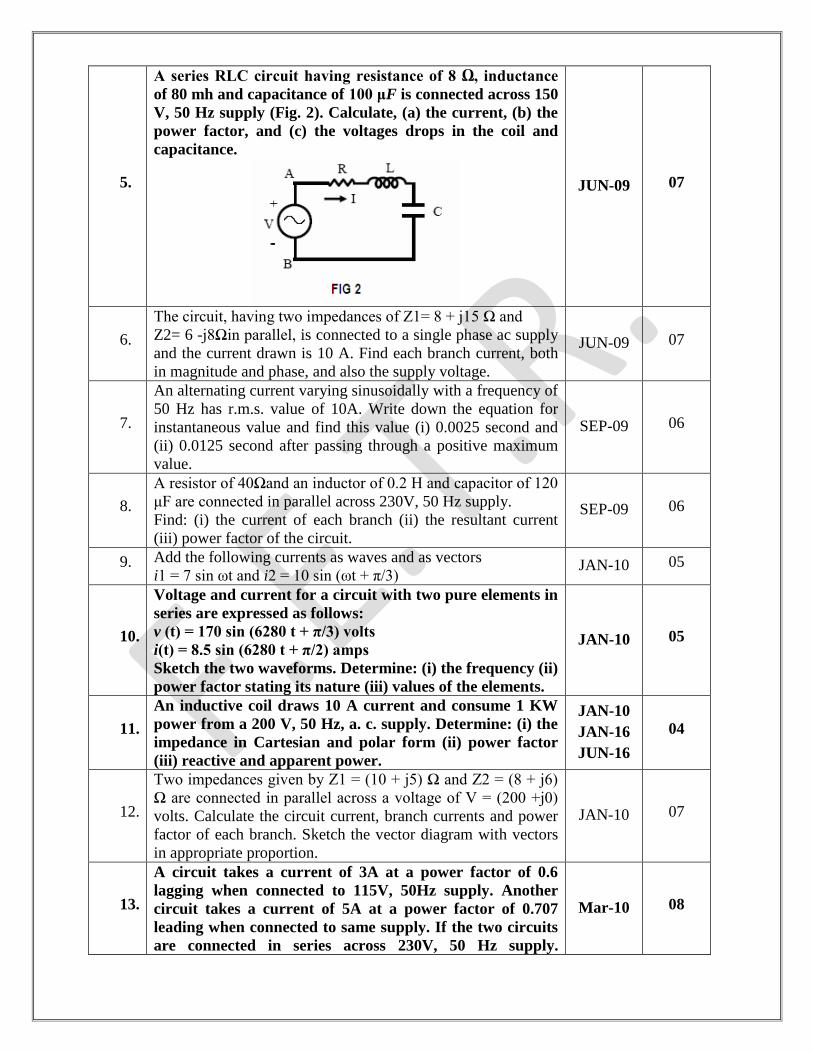
A series RLC circuit having resistance of 8 Ω, inductance
of 80 mh and capacitance of 100 μF is connected across 150
V, 50 Hz supply (Fig. 2). Calculate, (a) the current, (b) the
power factor, and (c) the voltages drops in the coil and
capacitance.
JUN-09 07
6.
The circuit, having two impedances of Z1= 8 + j15 Ω and
Z2= 6 -j8Ωin parallel, is connected to a single phase ac supply
and the current drawn is 10 A. Find each branch current, both
in magnitude and phase, and also the supply voltage.
JUN-09 07
7.
An alternating current varying sinusoidally with a frequency of
50 Hz has r.m.s. value of 10A. Write down the equation for
instantaneous value and find this value (i) 0.0025 second and
(ii) 0.0125 second after passing through a positive maximum
value.
SEP-09 06
8.
A resistor of 40Ωand an inductor of 0.2 H and capacitor of 120
μF are connected in parallel across 230V, 50 Hz supply.
Find: (i) the current of each branch (ii) the resultant current
(iii) power factor of the circuit.
SEP-09 06
9. Add the following currents as waves and as vectors
i1 = 7 sin ωt and i2 = 10 sin (ωt + π/3) JAN-10 05
10.
Voltage and current for a circuit with two pure elements in
series are expressed as follows:
v (t) = 170 sin (6280 t + π/3) volts
i(t) = 8.5 sin (6280 t + π/2) amps
Sketch the two waveforms. Determine: (i) the frequency (ii)
power factor stating its nature (iii) values of the elements.
JAN-10 05
11.
An inductive coil draws 10 A current and consume 1 KW
power from a 200 V, 50 Hz, a. c. supply. Determine: (i) the
impedance in Cartesian and polar form (ii) power factor
(iii) reactive and apparent power.
JAN-10
JAN-16
JUN-16
04
12.
Two impedances given by Z1 = (10 + j5) Ω and Z2 = (8 + j6)
Ω are connected in parallel across a voltage of V = (200 +j0)
volts. Calculate the circuit current, branch currents and power
factor of each branch. Sketch the vector diagram with vectors
in appropriate proportion.
JAN-10 07
13.
A circuit takes a current of 3A at a power factor of 0.6
lagging when connected to 115V, 50Hz supply. Another
circuit takes a current of 5A at a power factor of 0.707
leading when connected to same supply. If the two circuits
are connected in series across 230V, 50 Hz supply.
Mar-10 08
Calculate the (i) current (ii) power consumed (iii) Power
factor.
14. Three impedances Z1 = 5-j10 Ω, Z2 =2+j20 Ω and Z3 =
4+j2Ω are connected in parallel. If the total current is 20A,
Find the current shared by each.
MAR-10 06
15.
A series RLC circuit consists of a resistance of 500 5,
inductance of 50mH and a capacitance of 20 pF. Find
1. The resonant frequency.
2. The Q-factor of the circuit at resonance.
3. The half power frequency.
JUN-10
JAN-15 05
16.
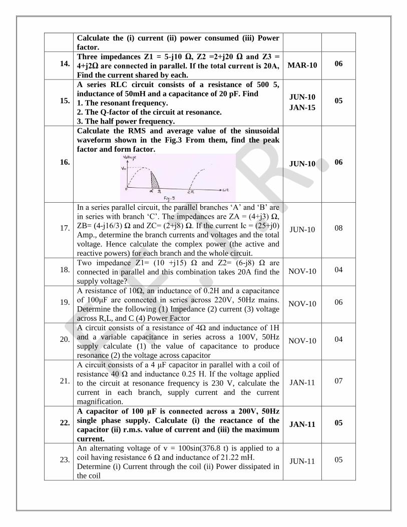
Calculate the RMS and average value of the sinusoidal
waveform shown in the Fig.3 From them, find the peak
factor and form factor.
JUN-10 06
17.
In a series parallel circuit, the parallel branches „A‟ and „B‟ are
in series with branch „C‟. The impedances are ZA = (4+j3) Ω,
ZB= (4-j16/3) Ω and ZC= (2+j8) Ω. If the current Ic = (25+j0)
Amp., determine the branch currents and voltages and the total
voltage. Hence calculate the complex power (the active and
reactive powers) for each branch and the whole circuit.
JUN-10 08
18. Two impedance Z1= (10 +j15) Ω and Z2= (6-j8) Ω are
connected in parallel and this combination takes 20A find the
supply voltage?
NOV-10 04
19.
A resistance of 10Ω, an inductance of 0.2H and a capacitance
of 100μF are connected in series across 220V, 50Hz mains.
Determine the following (1) Impedance (2) current (3) voltage
across R,L, and C (4) Power Factor
NOV-10 06
20.
A circuit consists of a resistance of 4Ω and inductance of 1H
and a variable capacitance in series across a 100V, 50Hz
supply calculate (1) the value of capacitance to produce
resonance (2) the voltage across capacitor
NOV-10 04
21.
A circuit consists of a 4 μF capacitor in parallel with a coil of
resistance 40 Ω and inductance 0.25 H. If the voltage applied
to the circuit at resonance frequency is 230 V, calculate the
current in each branch, supply current and the current
magnification.
JAN-11 07
22.
A capacitor of 100 μF is connected across a 200V, 50Hz
single phase supply. Calculate (i) the reactance of the
capacitor (ii) r.m.s. value of current and (iii) the maximum
current.
JAN-11 05
23.
An alternating voltage of v = 100sin(376.8 t) is applied to a
coil having resistance 6 Ω and inductance of 21.22 mH.
Determine (i) Current through the coil (ii) Power dissipated in
the coil
JUN-11 05
24.
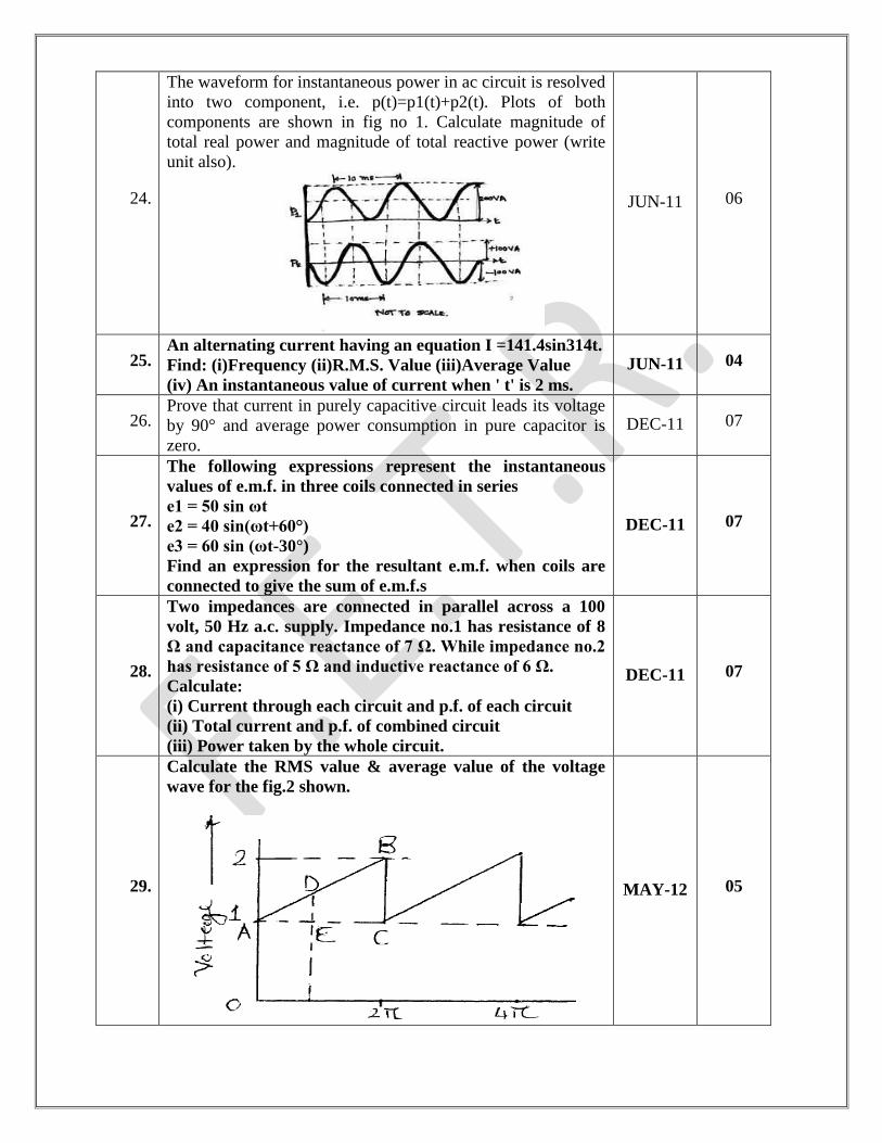
The waveform for instantaneous power in ac circuit is resolved
into two component, i.e. p(t)=p1(t)+p2(t). Plots of both
components are shown in fig no 1. Calculate magnitude of
total real power and magnitude of total reactive power (write
unit also).
JUN-11 06
25. An alternating current having an equation I =141.4sin314t.
Find: (i)Frequency (ii)R.M.S. Value (iii)Average Value
(iv) An instantaneous value of current when ' t' is 2 ms.
JUN-11 04
26. Prove that current in purely capacitive circuit leads its voltage
by 90° and average power consumption in pure capacitor is
zero.
DEC-11 07
27.
The following expressions represent the instantaneous
values of e.m.f. in three coils connected in series
e1 = 50 sin ωt
e2 = 40 sin(ωt+60°)
e3 = 60 sin (ωt-30°)
Find an expression for the resultant e.m.f. when coils are
connected to give the sum of e.m.f.s
DEC-11 07
28.
Two impedances are connected in parallel across a 100
volt, 50 Hz a.c. supply. Impedance no.1 has resistance of 8
Ω and capacitance reactance of 7 Ω. While impedance no.2
has resistance of 5 Ω and inductive reactance of 6 Ω.
Calculate:
(i) Current through each circuit and p.f. of each circuit
(ii) Total current and p.f. of combined circuit
(iii) Power taken by the whole circuit.
DEC-11 07
29.
Calculate the RMS value & average value of the voltage
wave for the fig.2 shown.
MAY-12 05
30. Two currents are given by expressions :
i1 = 40 sin (314t + 30º) and i2 = 20 sin(314t - 60º).
Find expression for (i1 - i2).
JUN-13 05
31.
A coil resistance 15 Ω and inductance 0.05 H is connected
in parallel with a non-inductive resistance of 20 Ω. The
circuit is connected across 200 V, 50 Hz supply. Determine
(i) current in each branch (ii) total current supplied (ii)
power factor of the combination.
JUN-13
JAN-16 07
32. A 12 resistor, a 40 F capacitor, and an 8 mH coil are in series
across an ac source. The resonant frequency is ________. DEC-13 01
33.
A resistance of 20 Ω, an inductance of 0.2 H and a
capacitance of 100 µF are Connected in series across 220
V,50 Hz supply. Find:
[1] Impedance
[2] Voltage across R,L & C
[3] Power factor & angle of lag [4] Active & apparent power
JUN-15 04
34.
An inductive circuit of resistance 2 Ω and inductance of
0.01 H is connected to a 250 V, 50 Hz supply. What is
capacitance required to be placed in parallel with this
circuit to produce resonance?
JAN-17 04
2-b)
Three Phase A.C. Circuits:
Necessity and Advantages of three phase systems, Generation of three phase
power, Phase sequence, Balanced supply and Balanced load; Relationship
between line and phase values of balanced three phase circuit; Power
Measurement in balanced three phase circuits.
ATTEMPT FOUR THEORY AND SIX EXAMPLES:
SR.
NO. QUESTION YEAR MARKS
THEORY
1.
Prove that power in a 3-phase balanced circuit can be
deduced from the readings of two watt meters. Draw the
relevant connection and Phasor diagrams. Discuss the nature
of power factor (i) when two readings are equal and positive
(ii) when two readings are equal but opposite in sign (iii)
when one wattmeter reads zero.
JAN-09 10
2.
The input power to a 3 phase load is measured by two
wattmeter method. The ratio of the readings of the two
wattmeter‟s connected for 3 phase balanced load is 4:1. The
load is inductive. Find the load power factor.
MAR-09 07
3. Establish relationship between line and phase voltages
and currents in balanced delta connection. Draw
complete phasor diagram of voltages and currents.
MAR-09
JUN-09
DEC-11
DEC-13
MAY-12
07
4.
Derive the relation between phase and line values of
voltages and currents in case of 3-phase (i) star (ii) delta
connection.
OR
Establish relation between line voltage & phase voltage
and current relation in 3-phase star connection. Draw
phasor diagram.
OR
For a 3 phase balanced star connected system develop
the relationship between the following with the help of
phasor diagram:
1. Line Voltage and Phase Voltage
2. Line Current and Phase Current
JAN-10
JUN-09
JUN-16
JAN-17
07
5.
Show that the power input to the three phase circuit can
be measured by two wattmeter connected properly in the
circuit.
OR
A balanced three phase supply is given to a star
connected load. Give proof of two wattmeter method for
MAY-12
JUN-11
MAR-10
JAN-11
JUN-13
07
this system. State demerits of this method.
OR
Prove the equation for measurement of Electrical power
in 3-phase circuit by two wattmeter method. Also draw
phasor diagram.
JAN-15
JAN-10
JUN-15
JAN-16
6. Establish relation between line voltage & phase voltage and
current relation in 3-phase star connection. Draw phasor
diagram.
JUN-13 07
7. For zero power factor load of 3-phase ckt.,if we measure the
power by 2- wattmeter method then readings of wattmeter
are ___________
JUN-15 01
8. Explain in brief the following for 3-phase AC circuit : [1] Phase sequence[2] Line voltage[3] Phase voltage
JUN-15
JAN-16 03
9. Give advantages of Two Wattmeter Method. JUN-16 03
10. For unity power factor load of 3-phase ckt.,if we measure the
power by 2-wattmeter method then readings of wattmeters
are__________
JAN-16 01
11. The three phase voltages are displaced by ____________
radians from each other JUN-16 01
12. If process of three-phase power measurement for balanced
load by two wattmeter method shows equal readings of both
wattmeters, what will be the power factor of load?
JAN-17 01
EXAMPLES
1.
Three similar coils each of resistance 28ohm and
inductance 0.7H are connected in (i) star (ii) delta. If the
supply voltage is 230V, 50Hz, calculate the line current
and total power absorbed.
JAN-09 04
2.
Three 100 Ω non-inductive resistances are connected in (a)
star (b) delta, across a 400 V, 50 Hz, 3-phase supply mains.
Calculate the power taken from the supply system in each
case.
JAN-10 05
3.
Three identical coils each of (4.2 +j5.6) Ω are connected
in star across a 415 V, 3 phase, 50 Hz AC supply. Find
1. Phase voltage. 2. Phase current.
3. Readings of two wattmeter’s W1 and W2 when they
are connected to measure the total power.
JUN-10
DEC-13 05
4.
A delta connected load having branch impedances of (15
+j20) Ω is connected to a 220V, 3 phase AC supply. Find
1. Line currents.
2. Per phase power consumed.
3. What is the phasor sum of the line currents? Why does it
have this value?
JUN-10 07
5.
A balanced star connected load of (4+j3) Ω per phase is
connected to a balance 3 phase 400V supply. Fine the
line current, power factor, active power and reactive
power.
NOV-10 06
6.
A 3-phase load consists of three similar inductive coils of
resistances of 50 Ω and inductance 0.3 H. The supply is
415 V 50 Hz. Calculate :(i) the line current (ii)the power
factor and the total power when the load is star connected.
JAN-11 07
7.
A balanced three phase power supply is connected to a
balanced load. Derive the expression of instantaneous
power of phase A, pa(t). Obtain expression of p(t), where
p(t) is summation of instantaneous powers of all three
phases. Assume that Va(t)=Vmsinωtand ia (t)=Imsin(ωt-Φ).
JUN-11 04
8.
Two wattmeter’s connected to measure three phase
power for star connected loads read 10.37 Kw and 5.185
Kw. The line current is 10 Amp. Calculate (i) Line and
phase voltage. (ii) Resistance and reactance per phase.
DEC-11 07
9.
For a balanced delta connected load supplied at 3-phase
, 240 V ac supply , the two wattmeter readings are :
(3210) & (-1710) W. Find out total power factor &
current
JAN-16 04
10.
A ∆-connected balanced 3-phase load is supplied from
400 V, 3-phase mains. The line current is 20 A & the
power taken by load is 10 MW. Find
[1] Impedance in each branch
[2] Power factor of the load [3] Line current & power consumed, if same load is
connected in star.
JUN-15 04
11.
For a balanced delta connected load supplied at 3-
phase, 400 V ac supply, the two wattmeter readings are:
7.8kW and 2.55kW. Find out load power factor & line
current.
JUN-16 04
12.
Two watt-meters are used for measuring three-phase power
input to the motor. if reading of meters are 7 kW and 2 kW
respectively, calculate input power and power factor of the
motor.
JAN-2017 04
3-a)
Batteries, Wiring, Illumination & Electrical Safety:
Batteries and Fuel Cell:
Introduction of Batteries; The Simple cell, E.M.F and internal resistance of a
cell; Primary and Secondary cells, Cell capacity; Types & Specifications of
Batteries; Charging & Discharging of Battery; Safe disposal of Batteries; Fuel
cell: Principle & Types of fuel cell.
ATTEMPT FOUR THEORIES:
SR.
NO. QUESTION YEAR MARKS
THEORY
1. Explain the following methods of charging a battery (i) Constant current method (ii) Constant voltage method
JAN-09 06
2. Explain the construction and working of any type of battery you know. What is its voltage when it is fully charged?
MAR-09
NOV-10 07
3. How do you estimate the life of a battery when charging and Discharging characteristics are available?
JUN-09 04
4. What do you mean by(i) Ampere hour efficiency and (ii) Watt-hour efficiency of a battery
SEP-09 02
5.
Using schematic block diagram, briefly explain charging of battery from a.c. supply mains.
OR Give connection diagram of a battery charging circuit.
OR State different charging methods of battery. Sketch diagram for one of these methods with all necessary labels.
JAN-10
JUN-10
MAY-12
JAN-17
04
03
6. Explain various types of grouping of cells, also discuss rating of battery.
MAR-10 08
7. Discuss electrical characteristics of batteries. JUN-10 04
8. Explain with neat sketch construction and working of lead acid battery
JAN-11 07
9. Explain in brief the following. [1] A-h & W-h capacity of a battery [2] ELCB [3] Illumination
JUN-15
DEC-15 03
10. Discuss the Lead acid battery with charging & discharging equations.
DEC-15 JAN-16
04
11. Wh efficiency of lead-acid cell is __________ Ah efficiency. JAN-16 01
12. Define A-H efficiency. JUN-16 01
3-b)
Electrical Wiring:
Types of wires and cables; Types of Connectors & Switches; System of wiring,
domestic and industrial wiring; Simple control circuit in domestic installation.
ATTEMPT THREE THEORIES:
SR
NO. QUESTION YEAR MARKS
THEORY
1. Draw the circuit diagram of tube light with the wiring of choke and starter. Explain the functioning of the circuit.
JAN-09
MAR-09
JUN-10
07
2. Draw and explain the wiring diagram of supply mains with energy meter and distribution box.
MAR-09 07
3.
Draw and explain the wiring diagram for the staircase wiring.
OR Draw a schematic block diagram showing positioning of major equipment in domestic wiring. Label the diagram. Also draw the circuit for controlling one lamp from two points (stair case wiring).
OR Draw the stair case wiring diagram. Which protective devices are utilized to protect house wring against overload/ short circuit?
JUN-09
MAR-09
JUNE-13
JAN-10
MAR-10
JUN-10
MAY-12
07
4. Explain the following wiring systems (i) Cleat wiring (ii) conduit wring
SEP-09 06
5.
Name various types of wiring systems commonly used in and explain any one of them in detail.
OR Enlist various types of wiring methods.
JAN-11
JAN-17
07
1.5
6.
Explain with neat sketch general construction of cable.
OR Discuss the types of cables used for residential and commercial wiring.
NOV-10
JUN-13
DEC-13
JUN-10
JAN-11
JAN-13
JUN-15
JUN-16
07
7. The choke in tube light wiring provides _________ JUN-15 01
3-c)
Illumination:
Types of lamps, fixtures & reflectors; Illumination schemes for domestic,
industrial & commercial premises; Lumen requirements for different categories.
ATTEMPT FOUR THEORIES:
SR
NO. QUESTION YEAR MARKS
THEORY
1.
Classify and explain various types of lighting
schemes.
OR
Explain the types of lighting schemes with suitable
diagrams.
OR
Classify various types of Lighting scheme and explain any
two
JAN-09
SEP-09
MAR-10
NOV-10
JUN-13
JAN-15
JUN-16
06
03
2. List lumens requirements for various categories of
illumination.
JUN-09
MAY-12 04
3. Explain construction and working of high pressure
mercury vapor lamp. SEP-09 04
4. State and explain different illumination schemes used
for domestic purpose. JAN-11 07
5.
Briefly discuss following terms:
(i) Luminous Flux (ii) Luminous intensity
(iii) Illumination (iv) Luminance
JAN-11 08
6. The ‘gauss’ is unit of __________. DEC-13 01
7. Define luminance DEC-13 01
8.
List the different types of lamps and explain
Florescent Lamp with wiring diagram.
OR
Enlist various types lamps.
JUN-14
JAN-15
JAN-2017
07
1.5
9. Explain in brief the following:
[1] Lumens
JUN-15
JUN-16 01
10. General guideline for wiring of domestic installation
with neat sketch for position of equipment. JUN-11 07
11. The gas used in sodium vapour lamp is _________ JUN-15 01
12. The filament used in incandescent lamp is made of________
JAN-16 01
13. Halogen lamp is a type of ______. (a) CFL (b) discharge lamp (c) incandescent lamp (d) LED lamp
JAN-17 01
3-d)
Safety & protection:
Safety precautions in handling electrical appliances; Electric shock, First aid for
electric shock other hazards of electrical laboratories & safety rules; Grounding
& Earthing - Importance of grounding and earthing, equipment for grounding,
Methods of earthing; Circuit protection devices: Fuses, MCB, ELCB & Relays.
ATTEMPT FIVE THEORIES:
SR
NO. QUESTION YEAR MARKS
THEORY
1. What is the function of fuse in an electrical circuit? State the
desirable properties of fuse element. JAN-09 02
2.
State the different methods of earthing and explain any
one of them.
OR
What are the different methods of earthing? Elaborate
pipe earthing method with the help of diagram.
JAN-09
JUN-09
JUN-10
JAN-13
JUN-15
JAN-2017
07
3.
Give the circuit diagram of earth leakage circuit breaker
(ELCB). Explain its working in brief and applications.
OR
What do you mean by earthing? Analyze earthing
concept with the help of a device-ELCB (Earth leakage
circuit breaker) used at our residence.
MAR-09
SEP-09
JUN-10
JAN-11
DEC-11
DEC-13
JUN-15
07
4. List various protective devices used in the electric circuits
and compare working of ELCB with MCB.
JUN-09
MAY-12
MAR-10
07
5. Explain the working of a miniature circuit breaker. SEP-09 04
6. What is Grounding & earthing? Analyze concept of
protection with a device- MCB used at our residence JAN-16 07
7. Give comparison between fuse and MCB with regard to
protection in wiring installation. JAN-10 04
8. What is the importance of earthing in electrical laboratory? MAR-10 04
9. What is an electric shock? Why grounding is required? NOV-10 04
10. State types of fuse and explain any one. JUN-13
JUN-16 04
11. Write function of „fuse‟ in electrical circuit. DEC-13 01
12. Explain in brief the following: [1] Rating of MCB JUN-15 01
13. MCB provides protection against ___________ JUN-15 01
14. Earthing is necessary to ___________ JUN-15 01
15. The material used for fuse should have _________ JUN-15 01
16. The resistance of human body is about _____.
(a) 1 Ω (b) 10 Ω (c) 100 Ω (d) 1000 Ω JAN-17 01
17. State two devices that provide protection against overload
and short circuit JAN-17 01