Embed Size (px)
Citation preview
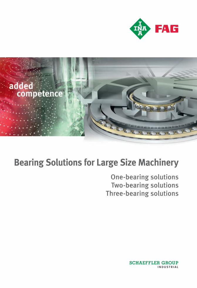
Bearing Solutions for Large Size MachineryOne-bearing solutions Two-bearing solutions
Three-bearing solutions
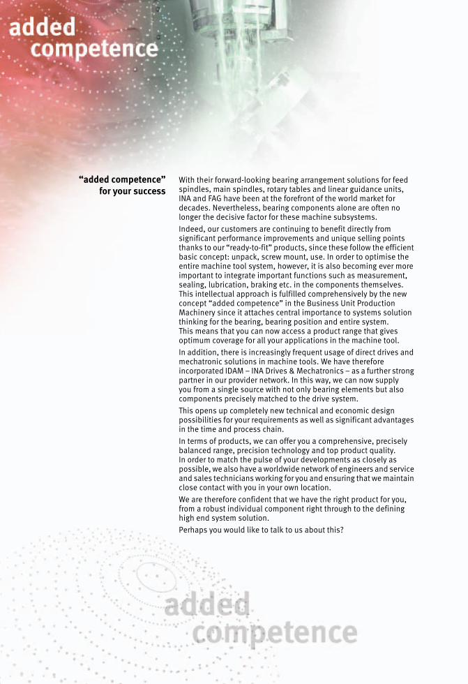
“added competence”for your success
With their forward-looking bearing arrangement solutions for feed spindles, main spindles, rotary tables and linear guidance units,INA and FAG have been at the forefront of the world market for decades. Nevertheless, bearing components alone are often no longer the decisive factor for these machine subsystems.Indeed, our customers are continuing to benefit directly from significant performance improvements and unique selling points thanks to our “ready-to-fit” products, since these follow the efficient basic concept: unpack, screw mount, use. In order to optimise the entire machine tool system, however, it is also becoming ever more important to integrate important functions such as measurement, sealing, lubrication, braking etc. in the components themselves. This intellectual approach is fulfilled comprehensively by the new concept “added competence” in the Business Unit Production Machinery since it attaches central importance to systems solution thinking for the bearing, bearing position and entire system.This means that you can now access a product range that gives optimum coverage for all your applications in the machine tool.In addition, there is increasingly frequent usage of direct drives and mechatronic solutions in machine tools. We have therefore incorporated IDAM – INA Drives & Mechatronics – as a further strong partner in our provider network. In this way, we can now supplyyou from a single source with not only bearing elements but also components precisely matched to the drive system.This opens up completely new technical and economic design possibilities for your requirements as well as significant advantages in the time and process chain.In terms of products, we can offer you a comprehensive, precisely balanced range, precision technology and top product quality.In order to match the pulse of your developments as closely as possible, we also have a worldwide network of engineers and service and sales technicians working for you and ensuring that we maintain close contact with you in your own location.We are therefore confident that we have the right product for you, from a robust individual component right through to the defining high end system solution.Perhaps you would like to talk to us about this?

Foreword
Bearing solutionsfor large size machinery
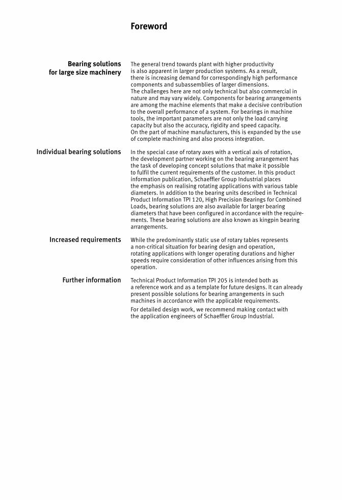
The general trend towards plant with higher productivityis also apparent in larger production systems. As a result,there is increasing demand for correspondingly high performance components and subassemblies of larger dimensions.The challenges here are not only technical but also commercial in nature and may vary widely. Components for bearing arrangements are among the machine elements that make a decisive contribution to the overall performance of a system. For bearings in machine tools, the important parameters are not only the load carrying capacity but also the accuracy, rigidity and speed capacity.On the part of machine manufacturers, this is expanded by the use of complete machining and also process integration.
Individual bearing solutions In the special case of rotary axes with a vertical axis of rotation,the development partner working on the bearing arrangement has the task of developing concept solutions that make it possibleto fulfil the current requirements of the customer. In this product information publication, Schaeffler Group Industrial placesthe emphasis on realising rotating applications with various table diameters. In addition to the bearing units described in Technical Product Information TPI 120, High Precision Bearings for Combined Loads, bearing solutions are also available for larger bearing diameters that have been configured in accordance with the require-ments. These bearing solutions are also known as kingpin bearing arrangements.
Increased requirements While the predominantly static use of rotary tables representsa non-critical situation for bearing design and operation,rotating applications with longer operating durations and higher speeds require consideration of other influences arising from this operation.
Further information Technical Product Information TPI 205 is intended both asa reference work and as a template for future designs. It can already present possible solutions for bearing arrangements in such machines in accordance with the applicable requirements.For detailed design work, we recommend making contact withthe application engineers of Schaeffler Group Industrial.

4 TPI 205 Schaeffler Group Industrial
Schaeffler Group Industrial TPI 205 5
Page
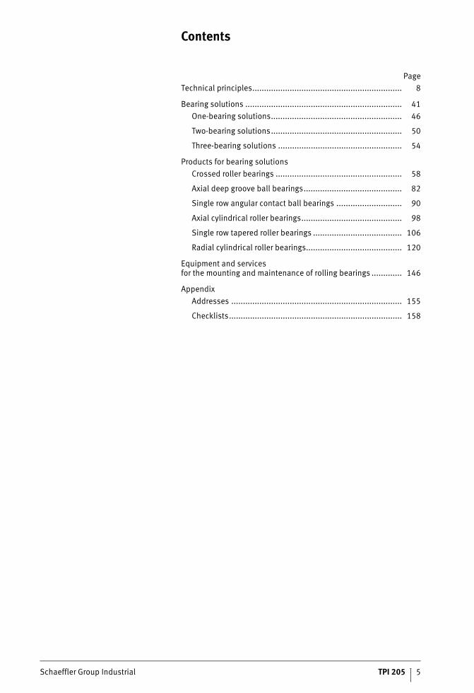
Contents
Technical principles................................................................ 8
Bearing solutions ................................................................... 41One-bearing solutions........................................................ 46
Two-bearing solutions........................................................ 50
Three-bearing solutions ..................................................... 54
Products for bearing solutionsCrossed roller bearings ...................................................... 58
Axial deep groove ball bearings.......................................... 82
Single row angular contact ball bearings ............................ 90
Axial cylindrical roller bearings........................................... 98
Single row tapered roller bearings ...................................... 106
Radial cylindrical roller bearings......................................... 120
Equipment and servicesfor the mounting and maintenance of rolling bearings ............. 146
AppendixAddresses ......................................................................... 155
Checklists.......................................................................... 158
0001
76CF
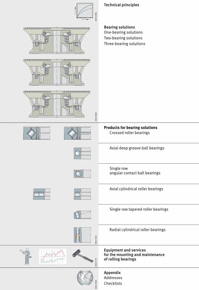
Technical principles
Bearing solutionsOne-bearing solutionsTwo-bearing solutionsThree-bearing solutions
Products for bearing solutionsCrossed roller bearings
Axial deep groove ball bearings
Single rowangular contact ball bearings
Axial cylindrical roller bearings
Single row tapered roller bearings
Radial cylindrical roller bearings
Equipment and servicesfor the mounting and maintenanceof rolling bearings
AppendixAddressesChecklists
0001
5CE8
0001
76D
000
0176
D1
0001
773F
0001
74D
A
Technical principlesSelection criteriaLoad carrying capacity and rating lifeFriction and increases in temperatureSpeedsLubricationBearing dataDesign of bearing arrangementsMounting
Schaeffler Group Industrial TPI 205 9
Page
Technical principles
Selection criteria Procedure for bearing selection ................................................. 10Geometrical boundary conditions.......................................... 10Speed................................................................................... 10Workpiece accuracy .............................................................. 10Rating life ............................................................................. 11Safety factors........................................................................ 11Dynamic load carrying capacity ............................................. 11Different loads ...................................................................... 11Further guidelines ................................................................. 11
Load carrying capacity andrating life
Basic rating life ......................................................................... 12Equivalent dynamic load ....................................................... 12
Friction andincreases in temperature
Friction...................................................................................... 13Heat dissipation ................................................................... 13Determining the friction values.............................................. 14
Speeds Speeds for bearing combinations............................................... 17
Limiting speed........................................................................... 17
Lubrication Lubricant selection .................................................................... 18
Recommended oil viscosity........................................................ 19
Oil selection .............................................................................. 21
Recirculating lubrication with moderate andlarger quantities of oil................................................................ 22
Bearing data Dimensional and geometrical tolerances.................................... 27
Chamfer dimensions.................................................................. 33
Designof bearing arrangements
Adjacent construction................................................................ 36
Shaft and housing tolerances .................................................... 36
Mounting One-bearing solutions ............................................................... 39
Two-bearing solutions ............................................................... 39
Three-bearing solutions ............................................................. 39
10 TPI 205 Schaeffler Group Industrial
Selection criteria
Procedurefor bearing selection
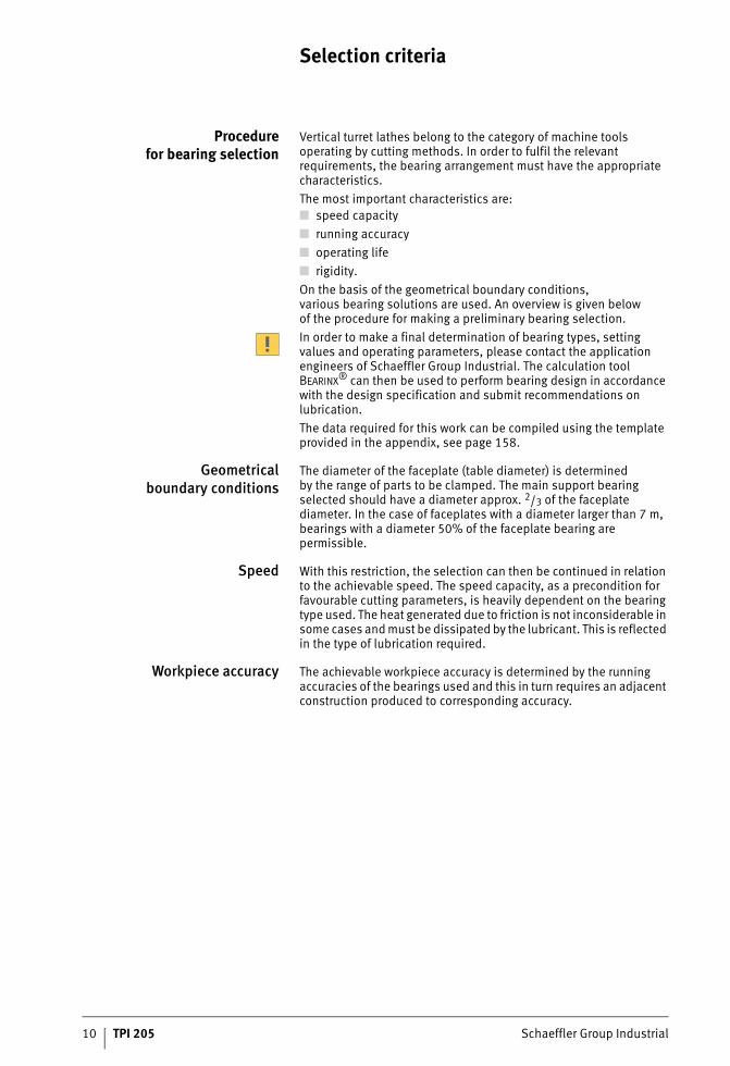
Vertical turret lathes belong to the category of machine tools operating by cutting methods. In order to fulfil the relevant requirements, the bearing arrangement must have the appropriate characteristics.The most important characteristics are:■ speed capacity■ running accuracy■ operating life■ rigidity.On the basis of the geometrical boundary conditions,various bearing solutions are used. An overview is given belowof the procedure for making a preliminary bearing selection.In order to make a final determination of bearing types, setting values and operating parameters, please contact the application engineers of Schaeffler Group Industrial. The calculation tool BEARINX® can then be used to perform bearing design in accordance with the design specification and submit recommendations on lubrication.The data required for this work can be compiled using the template provided in the appendix, see page 158.
Geometricalboundary conditions
The diameter of the faceplate (table diameter) is determinedby the range of parts to be clamped. The main support bearing selected should have a diameter approx. 2/3 of the faceplate diameter. In the case of faceplates with a diameter larger than 7 m, bearings with a diameter 50% of the faceplate bearing are permissible.
Speed With this restriction, the selection can then be continued in relation to the achievable speed. The speed capacity, as a precondition for favourable cutting parameters, is heavily dependent on the bearing type used. The heat generated due to friction is not inconsiderable in some cases and must be dissipated by the lubricant. This is reflected in the type of lubrication required.
Workpiece accuracy The achievable workpiece accuracy is determined by the running accuracies of the bearings used and this in turn requires an adjacent construction produced to corresponding accuracy.
Schaeffler Group Industrial TPI 205 11
Rating life In order to achieve an adequate fatigue life Lh, the bearings must have an appropriate load carrying capacity, expressed in termsof their basic load ratings, that is dependent on the load.This can be influenced on the one hand by the bearing size andalso by the bearing type.
Safety factors For smooth running, the objective should be a factor fS � 4.It is not normally necessary to factor in any additional safetyin calculation.In special cases, such as approval specifications, internal specifications, requirements stipulated by inspection bodies etc., the appropriate safety factors must be applied.
Dynamic loadcarrying capacity
Bearings subjected to dynamic load, in other words bearingsthat undergo predominantly rotary motion, are dimensionedin accordance with their dynamic load carrying capacity.The size of a bearing under dynamic load can be checkedin approximate terms using the basic dynamic load ratings C andthe basic rating life L or Lh.
Different loads In general, different workpieces are produced on one machine type. This means that the bearings are subjected to different loads.The bearing design process must therefore take account of all the load cases in order to ensure that the bearings function acceptably.If the appropriate preload is selected for the bearing system,the minimum loads required can be ensured in all load cases. Minimum loads are necessary in order to ensure that the rolling elements move without slippage and with low levels of friction and wear. The preload in turn has an influence on the rigidity ofthe bearing system.
Further guidelines The performance capacity of the bearing arrangement is strongly influenced by clean, precise mounting and it is therefore important that the necessary care is taken here.
12 TPI 205 Schaeffler Group Industrial
Load carrying capacity and rating life
Basic rating life The basic rating life L10 and L10h is determined as follows:
L10 106 revolutions The basic rating life in millions of revolutions is the life reached orexceeded by 90% of a sufficiently large group of apparently identical bearings before the first evidence of material fatigue developsC kNBasic dynamic load ratingP kNEquivalent dynamic bearing load for radial and axial bearingsp –Life exponent;for roller bearings: p = 10/3for ball bearings: p =3L10h hThe basic rating life in operating hours according to the definition for L10n min–1
Operating speed.
Equivalent dynamicbearing load
The equivalent dynamic load P is a calculated value. This valueis constant in magnitude and direction; it is a radial load for radial bearings and an axial load for axial bearings.A load corresponding to P will give the same rating life asthe combined load occurring in practice.
P kNEquivalent dynamic bearing loadX –Radial factor given in the dimension tables or product descriptionFr kNRadial dynamic bearing loadY –Axial factor given in the dimension tables or product descriptionFa kNAxial dynamic bearing load.
This calculation method cannot be applied to axial cylindrical roller bearings. Combined loads are not permissible with these bearings.
LCP
p
10 = ⎛⎝⎜
⎞⎠⎟
Ln
CPh
p
1016 666= ⋅ ⎛
⎝⎜⎞⎠⎟
P X F Y Fr a= ⋅ + ⋅
Schaeffler Group Industrial TPI 205 13
Friction and increases in temperature
Friction The friction in a rolling bearing is made up of several components, see table. Due to the large number of influencing factors, such as dynamics in speed and load, tilting and skewing resultingfrom mounting and operation, the actual frictional torques and friction values may deviate significantly from the calculated values. If the frictional torque is an important design criterion,please consult the engineering service of the Schaeffler Group.
Frictional component andinfluencing factor
The idling friction is dependent on the lubricant quantity, speed, operating viscosity of the lubricant, seals and the running-in condition of the bearing.
Heat dissipation Friction is converted into heat. This must be dissipated fromthe bearing. At lower speeds, this may occur to an adequate extent via the adjacent construction. At higher speeds and with longer operating durations, heat must be dissipated by means ofthe lubricant.
Heat dissipationby the lubricant
Oil dissipates a portion of the heat. Recirculating oil lubricationwith additional cooling is particularly effective. Grease does not give dissipation of heat.
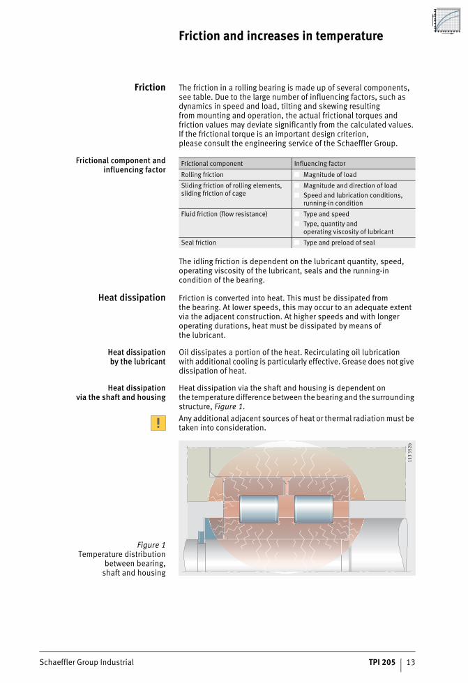
Heat dissipationvia the shaft and housing
Heat dissipation via the shaft and housing is dependent onthe temperature difference between the bearing and the surrounding structure, Figure 1.Any additional adjacent sources of heat or thermal radiation must be taken into consideration.
Frictional component Influencing factor
Rolling friction ■ Magnitude of load
Sliding friction of rolling elements, sliding friction of cage
■ Magnitude and direction of load■ Speed and lubrication conditions,
running-in condition
Fluid friction (flow resistance) ■ Type and speed■ Type, quantity and
operating viscosity of lubricant
Seal friction ■ Type and preload of seal
Figure 1Temperature distribution
between bearing,shaft and housing
113
352b
14 TPI 205 Schaeffler Group Industrial
Friction and increases in temperature
Determining the friction values For this process, the speed and load must be known.The type of lubrication, lubrication method and viscosity of lubricant at operating temperature are further important factors in calculation.Total frictional torque MR:
Frictional power NR:
Frictional torque as a function of speed:
Frictional torque as a function of load for cylindrical roller bearings:
Frictional torque as a function of load for ball bearings, tapered roller bearings and spherical roller bearings:
MR NmmTotal frictional torqueM0 NmmFrictional torque as a function of speedM1 NmmFrictional torque as a function of loadNR WFrictional powern min–1
Operating speedf0 –Bearing factor for frictional torque as a function of speed,see tables, page 15� mm2s–1
Kinematic viscosity of lubricant at operating temperature.In the case of grease, the decisive factor is the viscosity of the base oilat operating temperaturedM mmMean bearing diameter (d + D)/2f1 –Bearing factor for frictional torque as a function of load,see tables, page 15Fr, Fa NRadial load for radial bearings, axial load for axial bearingsP1 NDecisive load value for the frictional torque.For ball bearings, tapered roller bearings and spherical roller bearings,see table, page 16.
M M MR = +0 1
N Mn
R R= ⋅9550
M f n dM0 02 3 3 710= ⋅ ⋅( ) ⋅ ⋅ −�
/
M f F dM1 1= ⋅ ⋅
M f P dM1 1 1= ⋅ ⋅
Schaeffler Group Industrial TPI 205 15
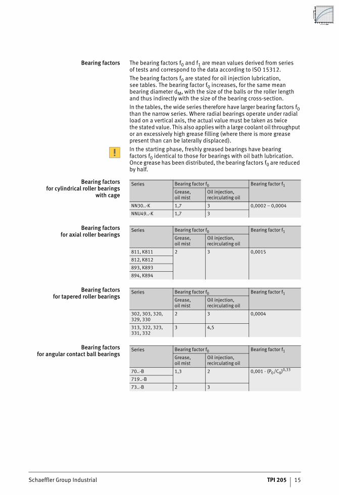
Bearing factors The bearing factors f0 and f1 are mean values derived from seriesof tests and correspond to the data according to ISO 15312.The bearing factors f0 are stated for oil injection lubrication,see tables. The bearing factor f0 increases, for the same mean bearing diameter dM, with the size of the balls or the roller length and thus indirectly with the size of the bearing cross-section.In the tables, the wide series therefore have larger bearing factors f0 than the narrow series. Where radial bearings operate under radial load on a vertical axis, the actual value must be taken as twicethe stated value. This also applies with a large coolant oil throughput or an excessively high grease filling (where there is more grease present than can be laterally displaced).In the starting phase, freshly greased bearings have bearing factors f0 identical to those for bearings with oil bath lubrication. Once grease has been distributed, the bearing factors f0 are reduced by half.
Bearing factorsfor cylindrical roller bearings
with cage
Bearing factorsfor axial roller bearings
Bearing factorsfor tapered roller bearings
Bearing factorsfor angular contact ball bearings
Series Bearing factor f0 Bearing factor f1
Grease,oil mist
Oil injection,recirculating oil
NN30..-K 1,7 3 0,0002 – 0,0004
NNU49..-K 1,7 3
Series Bearing factor f0 Bearing factor f1
Grease,oil mist
Oil injection,recirculating oil
811, K811 2 3 0,0015
812, K812
893, K893
894, K894
Series Bearing factor f0 Bearing factor f1
Grease,oil mist
Oil injection,recirculating oil
302, 303, 320,329, 330
2 3 0,0004
313, 322, 323,331, 332
3 4,5
Series Bearing factor f0 Bearing factor f1
Grease,oil mist
Oil injection,recirculating oil
70..-B 1,3 2 0,001 · (P0/C0)0,33
719..-B
73..-B 2 3
16 TPI 205 Schaeffler Group Industrial
Friction and increases in temperature
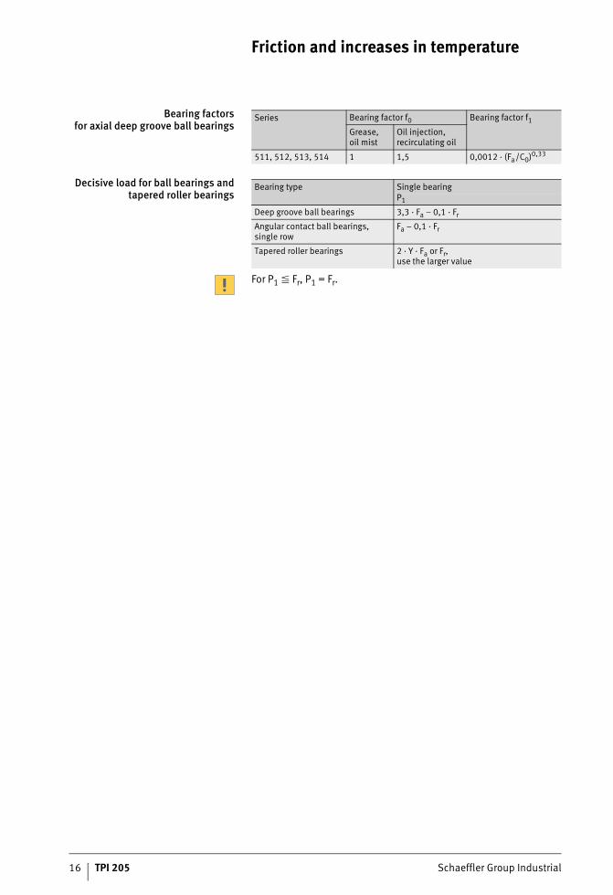
Bearing factorsfor axial deep groove ball bearings
Decisive load for ball bearings andtapered roller bearings
For P1 � Fr, P1 = Fr.
Series Bearing factor f0 Bearing factor f1
Grease,oil mist
Oil injection,recirculating oil
511, 512, 513, 514 1 1,5 0,0012 · (Fa/C0)0,33
Bearing type Single bearingP1
Deep groove ball bearings 3,3 · Fa – 0,1 · Fr
Angular contact ball bearings, single row
Fa – 0,1 · Fr
Tapered roller bearings 2 · Y · Fa or Fr,use the larger value

Schaeffler Group Industrial TPI 205 17
Speeds
Speedsfor bearing combinations
For bearing solutions in vertical turret lathes with combined bearings, the decisive factor for the maximum permissible speedis always the main bearing in the arrangement.
Limiting speed The limiting speed nG for oil and grease lubrication is basedon practical experience and takes account of additional criteriasuch as smooth running and centrifugal forces.The limiting speed must not be exceeded even under favourable operating and cooling conditions.
18 TPI 205 Schaeffler Group Industrial
Lubrication
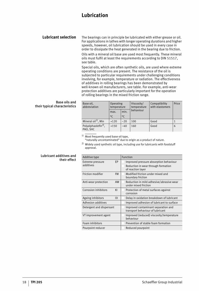
Lubricant selection The bearings can in principle be lubricated with either grease or oil. For applications in lathes with longer operating durations and higher speeds, however, oil lubrication should be used in every case in order to dissipate the heat generated in the bearing due to friction.Oils with a mineral oil base are used most frequently. These mineral oils must fulfil at least the requirements according to DIN 51517,see table.Special oils, which are often synthetic oils, are used where extreme operating conditions are present. The resistance of the oil is subjected to particular requirements under challenging conditions involving, for example, temperature or radiation. The effectiveness of additives in rolling bearings has been demonstrated by well-known oil manufacturers, see table. For example, anti-wear protection additives are particularly important for the operationof rolling bearings in the mixed friction range.
Base oils andtheir typical characteristics
1) Most frequently used base oil type,“naturally uncontaminated” due to origin as a product of nature.
2) Widely used synthetic oil type, including use for lubricants with foodstuff approval.
Lubricant additives andtheir effect
Base oil, abbreviation
Operating temperature
Viscosity/temperature behaviour
Compatibility with elastomers
Price
max. min.
°C °C
Mineral oil1), Min +120 –20 100 Good 1
Polyalphaolefin2), PAO, SHC
+150 –40 160 Good 6
Additive type Function
Extreme pressure additives
EP ■ Improved pressure absorption behaviour■ Reduction in wear through formation
of reaction layer
Friction modifier FM ■ Modified friction under mixed andboundary friction
Anti-wear protection AW ■ Reduction in mild adhesive/abrasive wear under mixed friction
Corrosion inhibitors KI ■ Protection of metal surfaces against corrosion
Ageing inhibitors OI ■ Delay in oxidation breakdown of lubricant
Adhesion additives ■ Improved adhesion of lubricant to surface
Detergent and dispersant ■ Improved contaminant separation and transport behaviour of lubricant
VT improvement agent ■ Improved (reduced) viscosity/temperature behaviour
Foam inhibitors ■ Prevention of stable foam formation
Pourpoint reducer ■ Reduced pourpoint
Schaeffler Group Industrial TPI 205 19
Recommended oil viscosity The achievable life and security against wear increase with increasing separation of the contact surfaces by a lubricant film. Since the lubricant film thickness increases with oil viscosity,an oil with a higher operating viscosity � should be selectedwhere possible.Very long life can be achieved if the viscosity ratio betweenthe existing and required viscosity is � = ���1 � 2. With increasing viscosity, however, the lubricant friction increases. Problems may occur with feed and removal of oil at low and even at normal temperatures.The oil selected must be sufficiently viscous that, on the one hand, the longest possible fatigue life is achieved but, on the other hand, the power loss due to increased friction is kept as low as possible.It must be ensured that the bearings are provided with sufficient oil at all times.
Operating viscosity In individual cases, the preferred level of operating viscosity cannot be achieved because:■ the oil selection is determined by other components in
the machine, which require a thin-bodied oil■ a sufficiently flowable oil is to be used for recirculating
lubrication in order to dissipate contaminants and heat fromthe bearing
■ higher temperatures or very low circumferential viscosityare present at some times and the operating viscosity that canbe achieved with the most viscous suitable oil is belowthe required viscosity.
In such cases, an oil with lower than recommended viscosity maybe used. The oil must then, however, contain effective additives and its suitability for lubrication must be demonstrated by means ofa rolling bearing test. Depending on the deviation from the nominal value, a reduction in fatigue life and the symptoms of wearon the functional surfaces must then be anticipated, as will be demonstrated by the calculation of the achievable life.For common viscosity classes in accordance with ISO and SAE, Figure 1, page 20 and table, page 20.
20 TPI 205 Schaeffler Group Industrial
Lubrication
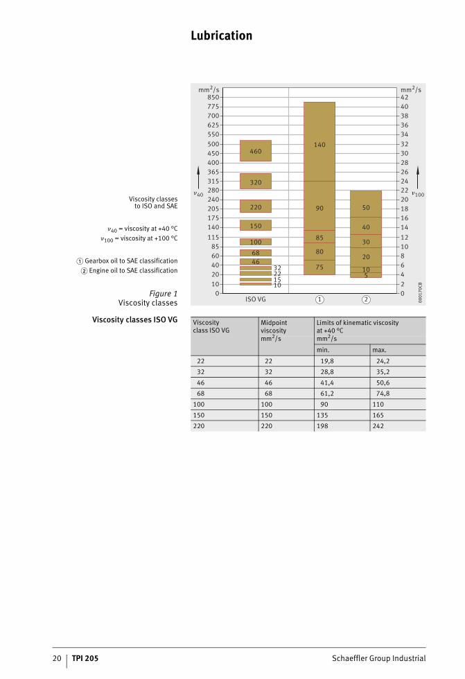
Viscosity classes ISO VG
Viscosity classesto ISO and SAE
�40 = viscosity at +40 °C�100 = viscosity at +100 °C
� Gearbox oil to SAE classification� Engine oil to SAE classification
Figure 1Viscosity classes 1 2
850775700625550500450400365315280240205175140115
8560402010
0
mm2/s424038363432302826242220181614121086420
mm2/s
140460
320
220
150
100
6846
32221510
90 50
40
30
20
105
85
80
75
�40 �100
ISO VG 0001
70CB
Viscosityclass ISO VG
Midpoint viscosity
Limits of kinematic viscosityat +40 °C
mm2/s mm2/s
min. max.
22 22 19,8 24,2
32 32 28,8 35,2
46 46 41,4 50,6
68 68 61,2 74,8
100 100 90 110
150 150 135 165
220 220 198 242
Schaeffler Group Industrial TPI 205 21
Oil selection The oil must be selected in accordance with the specific application. In most cases, the oils used are gearbox or hydraulic oils CLP or HLP of ISO VG 46, ISO VG 68 or ISO VG 100. The selection is dependent on the speed and the load ratio C/P.
High speed parameters If high circumferental velocities are present, an oil resistant to oxidation with a low foaming tendency and a favourable viscosity/temperature behaviour is advantageous. The maximum permissible speed parameter for axial cylindrical roller bearingsis n · dM = 250 000 min–1 · mm, while the maximum for axial deep groove ball bearings is n · dM = 440 000 min–1 · mm.Suitable synthetic oils with a good V/T behaviour are esters and polyalphaolefins PAO, since the viscosity of these oils showsa smaller reduction in viscosity as the temperature increases.In the starting phase when the temperature is normally low,high splashing losses and thus an increase in temperature are avoided; once the higher equilibrium temperature is reached,the viscosity is still sufficient to ensure lubrication.
High loads If the bearings are subjected to high loads (C/P � 7) or the operating viscosity � is lower than the reference viscosity �1, oils with anti-wear protection additives should be used (code P to DIN 51502).Anti-wear protection additives reduce the harmful effects of metallic contact occurring at various points. The suitability of anti-wear protection additives varies and is normally heavily dependenton temperature. Their effectiveness can only be assessed by means of testing in the rolling bearing (for example on our test rig FE 8).
22 TPI 205 Schaeffler Group Industrial
Lubrication
Recirculating lubricationwith moderate and
larger quantities of oil
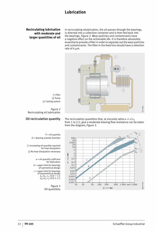
In recirculating relubrication, the oil passes through the bearings,is directed into a collection container and is then fed back intothe bearings, Figure 2. Wear particles and contaminants havea negative effect on the achievable life. It is therefore absolutely essential to provide a filter in order to separate out the wear particles and contaminants. The filter in the feed line should have a retention rate of 6 �m.
Oil recirculation quantity The recirculation quantities that, at viscosity ratios � = �/�1from 1 to 2,5, give a moderate bearing flow resistance can be taken from the diagram, Figure 3.
� Filter� Pump
� Cooling system
Figure 2Recirculating oil lubrication
M
1
2
3
155
185b
V = oil quantityD = bearing outside diameter
� Increasing oil quantity requiredfor heat dissipation
� No heat dissipation necessary
a = oil quantity sufficientfor lubrication
b = upper limit for bearingsof symmetrical design
c = upper limit for bearingsof asymmetrical design
a1; b1; c1: D/d 1,5a2; b2; c2: D/d � 1,5
Figure 3Oil quantities
c1 c2
b2
b1
a1
a2
c
b
a
10050
l/min2010
521
0,50,20,1
0,050,020,01
0,0050,0020,001
10 20 50 100 200 500 1 000 mm 3 000
1
2
D
V.
0001
737A
Schaeffler Group Industrial TPI 205 23
Operating conditions The recirculation quantities are matched to the operating conditions:■ Lubrication of the bearing requires only a very small quantity of
oil. In comparison, the lubrication quantities stated as sufficient (line a) are large, Figure 3, page 22. These oil quantities are recommended in order to ensure that all contact surfaces are completely supplied with oil even if the feed of oil to the bearing is unfavourable. The minimum quantities stated are used for lubrication if a low level of friction is required. The temperature level achieved in this case is comparable with that in oil bath lubrication.
■ If heat dissipation is required, larger oil quantities are necessary (line b), Figure 3, page 22. Since each bearing provides some resistance to the flow of oil, there are also upper limits for the oil quantities.
■ For bearings with an asymmetrical cross-section such as angular contact ball bearings, tapered roller bearings or axial spherical roller bearings, larger throughput quantities are permissible (line c) than for bearings with a symmetrical cross-section, Figure 3, page 22. This is due to the fact that bearings with an asymmetrical cross-section provide less resistance to the oil flow due to their pumping action.
At the stated limits, the unpressurised feed and backing-up of oilon the feed side of the bearing as far as just below the shaft isa precondition. The oil quantity that must be provided in individual cases in order to maintain an adequately low bearing temperatureis dependent on the conditions of heat input and dissipation.Values higher than those in area c are not advisable, Figure 3, page 22. The correct oil quantity can be determined by temperature measurement during initial operation of the machine and then regulated accordingly.
24 TPI 205 Schaeffler Group Industrial
Lubrication
Injection lubrication With increasing circumferential velocity, bearings with a symmetrical cross-section provide increasing resistance to the oil flow.If larger recirculation quantities are planned, the oil is injected specifically into the gap between the cage and bearing ring in the case of rolling bearings rotating at high speeds. With oil injection, smaller splashing losses occur.Normal oil quantities can be determined as a function ofthe speed parameter and bearing size. In this case, please consult the engineering service of the Schaeffler Group.The back-up of oil ahead of the bearing is prevented by injectingoil at points that allow free entry into the bearing.If the outlet ducts ahead of and after the bearing arrangement are adequately dimensioned, this will ensure that the oil not consumed by the bearing and flowing through the bearing can escape without any build-up.
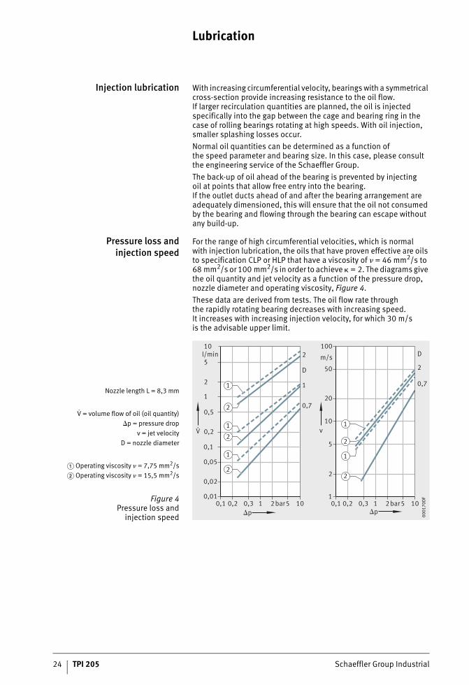
Pressure loss andinjection speed
For the range of high circumferential velocities, which is normalwith injection lubrication, the oils that have proven effective are oils to specification CLP or HLP that have a viscosity of � = 46 mm2/s to 68 mm2/s or 100 mm2/s in order to achieve � = 2. The diagrams give the oil quantity and jet velocity as a function of the pressure drop, nozzle diameter and operating viscosity, Figure 4.These data are derived from tests. The oil flow rate throughthe rapidly rotating bearing decreases with increasing speed.It increases with increasing injection velocity, for which 30 m/sis the advisable upper limit.
Nozzle length L = 8,3 mm
V = volume flow of oil (oil quantity)p = pressure drop
v = jet velocityD = nozzle diameter
� Operating viscosity � = 7,75 mm2/s� Operating viscosity � = 15,5 mm2/s
Figure 4Pressure loss and
injection speed
v
p p0,1 0,2 0,3 1 2bar5 10 0,1 0,2 0,3 1 2bar5 10
0,01
0,02
0,05
0,1
0,2
0,5
1
2
5
10l/min
0,7
1
2
D
1
2
5
10
100
m/s
20
50
0,7
2
D
V.
1
2
1
2
1
2
1
2
1
2
0001
70D
F
Schaeffler Group Industrial TPI 205 25
Design considerations Rolling bearings must be provided with lubricant as soon as the machine is switched on. In the case of recirculating oil lubrication, the pump should therefore start up before the bearing starts to move. An oil sump provided in addition to the recirculating lubrication system also contributes to operational security, since oil can be supplied from the sump for at least a certain period ifthe pump fails. At low temperatures, the recirculating oil quantity can initially be reduced to the quantity necessary for lubrication until the oil in the container has heated up. The assists in the designof the recirculation system (pump drive, oil return system).If lubrication is carried out using a larger oil quantity, outlet ducts must be provided in such a way as to prevent oil back-up that leads, mainly at high circumferential velocities, to significant power losses. The required diameter of the outlet line is dependent on the viscosity of the oil and the drop angles of the discharge pipes.Where there is a combination of several bearings, the appropriate lubricant quantity must be determined for each individual bearing. Lubrication of radial cylindrical roller bearings must be carried out with particular care, see Catalogue SP 1, Super Precision Bearings. In many cases, the radial cylindrical roller bearing is adequately supplied by the oil quantity from the upper bearing.
26 TPI 205 Schaeffler Group Industrial
Lubrication
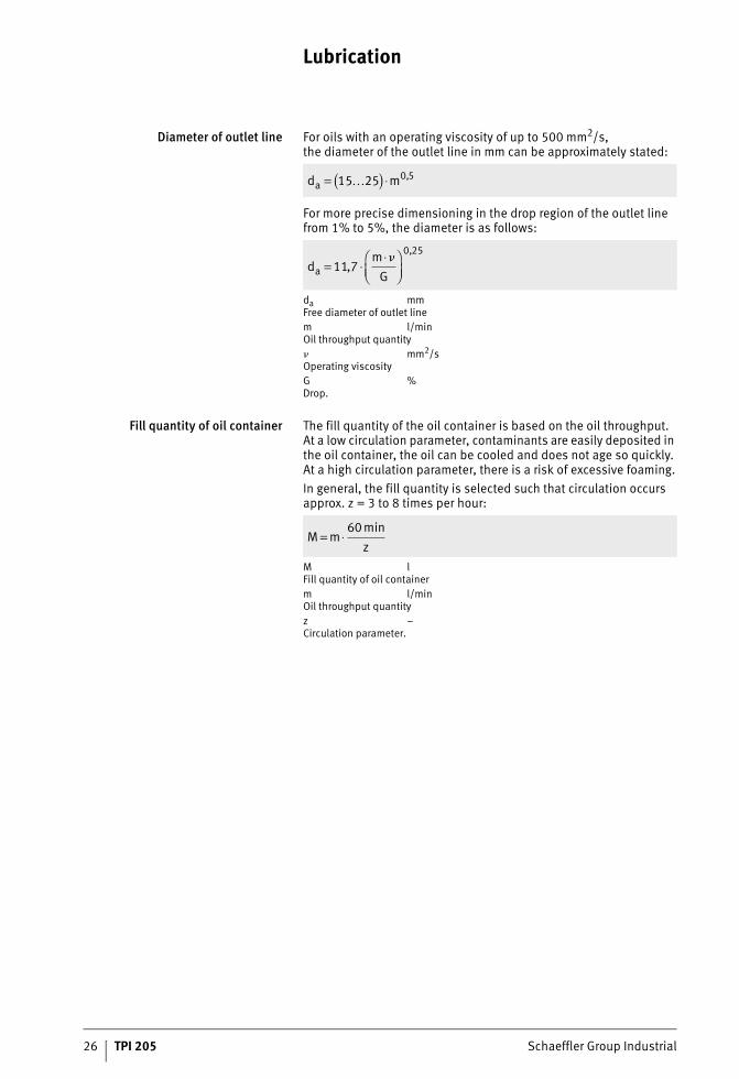
Diameter of outlet line For oils with an operating viscosity of up to 500 mm2/s,the diameter of the outlet line in mm can be approximately stated:
For more precise dimensioning in the drop region of the outlet line from 1% to 5%, the diameter is as follows:
da mmFree diameter of outlet linem l/minOil throughput quantity� mm2/sOperating viscosityG %Drop.
Fill quantity of oil container The fill quantity of the oil container is based on the oil throughput.At a low circulation parameter, contaminants are easily deposited in the oil container, the oil can be cooled and does not age so quickly. At a high circulation parameter, there is a risk of excessive foaming.In general, the fill quantity is selected such that circulation occurs approx. z = 3 to 8 times per hour:
M lFill quantity of oil containerm l/minOil throughput quantityz –Circulation parameter.
d ma = ( ) ⋅15 25 0 5K ,
dm
Ga = ⋅⋅⎛
⎝⎜⎞⎠⎟
11 70 25
,,
�
M mz
= ⋅60 min
Schaeffler Group Industrial TPI 205 27
Bearing data
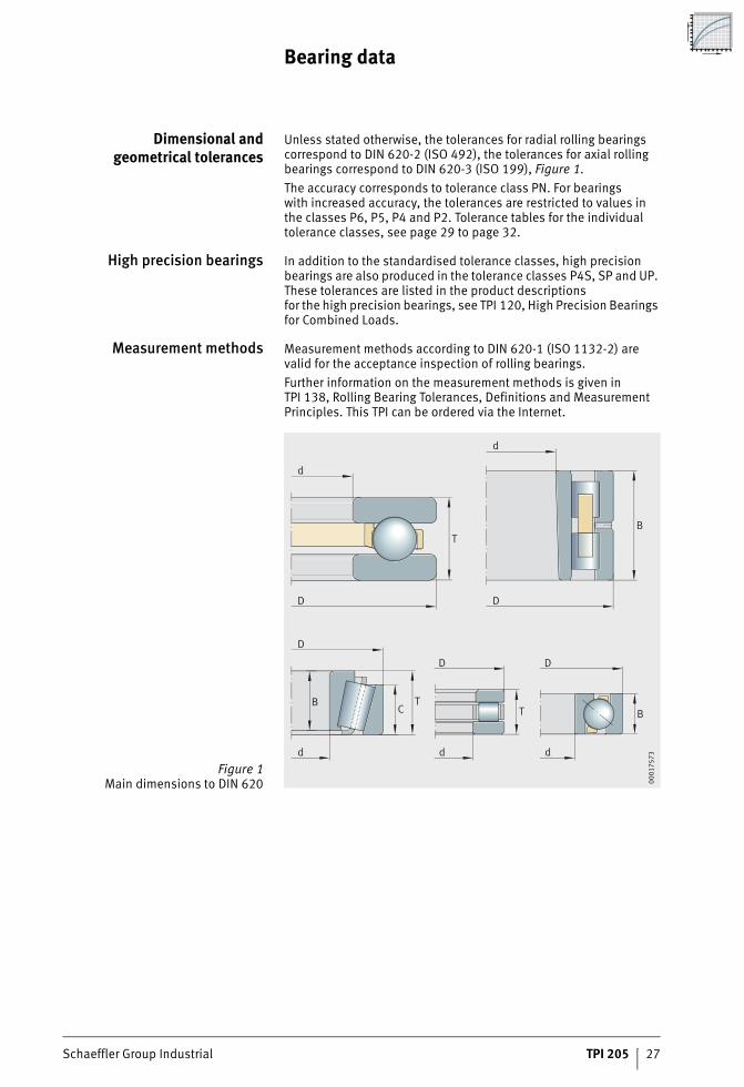
Dimensional andgeometrical tolerances
Unless stated otherwise, the tolerances for radial rolling bearings correspond to DIN 620-2 (ISO 492), the tolerances for axial rolling bearings correspond to DIN 620-3 (ISO 199), Figure 1.The accuracy corresponds to tolerance class PN. For bearingswith increased accuracy, the tolerances are restricted to values inthe classes P6, P5, P4 and P2. Tolerance tables for the individual tolerance classes, see page 29 to page 32.
High precision bearings In addition to the standardised tolerance classes, high precision bearings are also produced in the tolerance classes P4S, SP and UP. These tolerances are listed in the product descriptionsfor the high precision bearings, see TPI 120, High Precision Bearings for Combined Loads.
Measurement methods Measurement methods according to DIN 620-1 (ISO 1132-2) are valid for the acceptance inspection of rolling bearings.Further information on the measurement methods is given in TPI 138, Rolling Bearing Tolerances, Definitions and Measurement Principles. This TPI can be ordered via the Internet.
Figure 1Main dimensions to DIN 620
D
d
T
D
d
B
B
DD
d
d
T
TC
D
d
B
0001
7573
28 TPI 205 Schaeffler Group Industrial
Bearing data
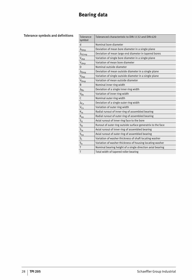
Tolerance symbols and definitions Tolerance symbol
Toleranced characteristic to DIN 1132 and DIN 620
d Nominal bore diameter
dmp Deviation of mean bore diameter in a single plane
d1mp Deviation of mean large end diameter in tapered bores
Vdsp Variation of single bore diameter in a single plane
Vdmp Variation of mean bore diameter
D Nominal outside diameter
Dmp Deviation of mean outside diameter in a single plane
VDsp Variation of single outside diameter in a single plane
VDmp Variation of mean outside diameter
B Nominal inner ring width
Bs Deviation of a single inner ring width
VBs Variation of inner ring width
C Nominal outer ring width
Cs Deviation of a single outer ring width
VCs Variation of outer ring width
Kia Radial runout of inner ring of assembled bearing
Kea Radial runout of outer ring of assembled bearing
Sd Axial runout of inner ring face to the bore
SD Runout of outer ring outside surface generatrix to the face
Sia Axial runout of inner ring of assembled bearing
Sea Axial runout of outer ring of assembled bearing
Si Variation of washer thickness of shaft locating washer
Se Variation of washer thickness of housing locating washer
T Nominal bearing height of a single direction axial bearing
T Total width of tapered roller bearing
Schaeffler Group Industrial TPI 205 29
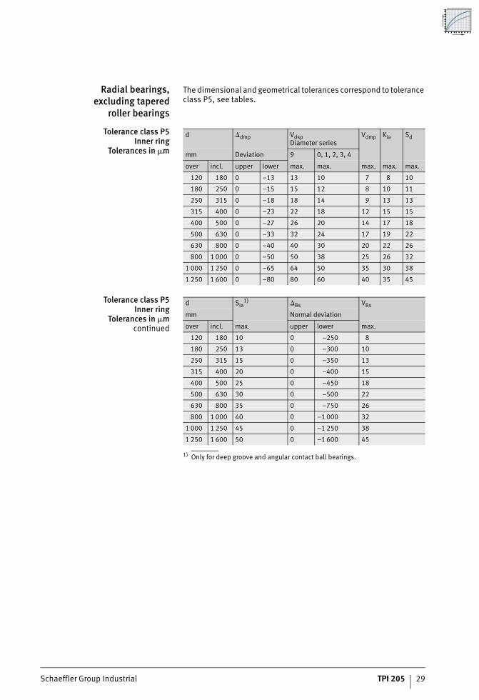
Radial bearings,excluding tapered
roller bearings
The dimensional and geometrical tolerances correspond to tolerance class P5, see tables.
Tolerance class P5Inner ring
Tolerances in �m
Tolerance class P5Inner ring
Tolerances in �mcontinued
1) Only for deep groove and angular contact ball bearings.
d dmp VdspDiameter series
Vdmp Kia Sd
mm Deviation 9 0, 1, 2, 3, 4
over incl. upper lower max. max. max. max. max.
120 180 0 –13 13 10 7 8 10
180 250 0 –15 15 12 8 10 11
250 315 0 –18 18 14 9 13 13
315 400 0 –23 22 18 12 15 15
400 500 0 –27 26 20 14 17 18
500 630 0 –33 32 24 17 19 22
630 800 0 –40 40 30 20 22 26
800 1 000 0 –50 50 38 25 26 32
1 000 1 250 0 –65 64 50 35 30 38
1 250 1 600 0 –80 80 60 40 35 45
d Sia1) Bs VBs
mm Normal deviation
over incl. max. upper lower max.
120 180 10 0 –250 8
180 250 13 0 –300 10
250 315 15 0 –350 13
315 400 20 0 –400 15
400 500 25 0 –450 18
500 630 30 0 –500 22
630 800 35 0 –750 26
800 1 000 40 0 –1 000 32
1 000 1 250 45 0 –1 250 38
1 250 1 600 50 0 –1 600 45
30 TPI 205 Schaeffler Group Industrial
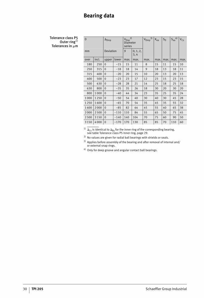
Bearing data
Tolerance class P5Outer ring1)
Tolerances in �m
1) Cs is identical to Bs for the inner ring of the corresponding bearing,see table Tolerance class P5 Inner ring, page 29.
2) No values are given for radial ball bearings with shields or seals.3) Applies before assembly of the bearing and after removal of internal and/
or external snap rings.4) Only for deep groove and angular contact ball bearings.
D Dmp VDsp2)
Diameter series
VDmp3) Kea SD Sea
4) VCs
9 0, 1, 2, 3, 4
mm Deviation
over incl. upper lower max. max. max. max. max. max. max.
180 250 0 –15 15 11 8 15 11 15 10
250 315 0 –18 18 14 9 18 13 18 11
315 400 0 –20 20 15 10 20 13 20 13
400 500 0 –23 23 17 12 23 15 23 15
500 630 0 –28 28 21 14 25 18 25 18
630 800 0 –35 35 26 18 30 20 30 20
800 1 000 0 –40 44 34 23 35 25 35 24
1 000 1 250 0 –50 54 40 30 40 30 45 28
1 250 1 600 0 –65 70 54 35 45 35 55 32
1 600 2 000 0 –85 82 64 45 55 40 65 38
2 000 2 500 0 –110 110 84 55 65 50 75 45
2 500 3 150 0 –140 140 104 70 75 60 90 50
3 150 4 000 0 –170 170 130 85 85 70 110 60
Schaeffler Group Industrial TPI 205 31
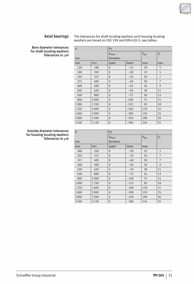
Axial bearings The tolerances for shaft locating washers and housing locating washers are based on ISO 199 and DIN 620-3, see tables.
Bore diameter tolerancesfor shaft locating washers
Tolerances in �m
Outside diameter tolerancesfor housing locating washers
Tolerances in �m
d P5
dmp Vdp Si
mm Deviation
over incl. upper lower max. max.
120 180 0 –25 19 5
180 250 0 –30 23 5
250 315 0 –35 26 7
315 400 0 –40 30 7
400 500 0 –45 34 9
500 630 0 –50 38 11
630 800 0 –75 56 13
800 1 000 0 –100 75 15
1 000 1 250 0 –125 95 18
1 250 1 600 0 –160 120 21
1 600 2 000 0 –200 150 25
2 000 2 500 0 –250 190 30
2 500 3 150 0 –300 224 35
D P5
Dmp VDp Se
mm Deviation
over incl. upper lower max.
180 250 0 –30 22 5
250 315 0 –35 26 7
315 400 0 –40 30 7
400 500 0 –45 34 9
500 630 0 –50 38 11
630 800 0 –75 55 13
800 1 000 0 –100 75 15
1 000 1 250 0 –125 90 18
1 250 1 600 0 –160 120 21
1 600 2 000 0 –200 150 25
2 000 2 500 0 –250 190 30
2 500 3 150 0 –300 224 35
32 TPI 205 Schaeffler Group Industrial
Bearing data
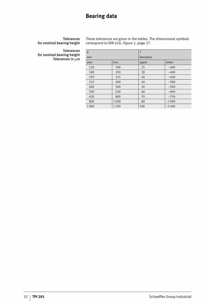
Tolerancesfor nominal bearing height
These tolerances are given in the tables. The dimensional symbols correspond to DIN 620, Figure 1, page 27.
Tolerancesfor nominal bearing height
Tolerances in �m
d T
mm Deviation
over incl. upper lower
120 180 25 –400
180 250 30 –400
250 315 40 –400
315 400 40 –500
400 500 50 –500
500 630 60 –600
630 800 70 –750
800 1 000 80 –1 000
1 000 1 250 100 –1 400
Schaeffler Group Industrial TPI 205 33
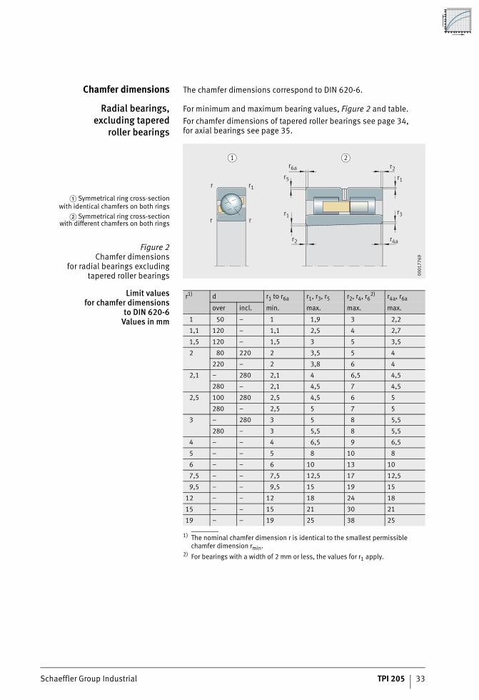
Chamfer dimensions The chamfer dimensions correspond to DIN 620-6.
Radial bearings,excluding tapered
roller bearings
For minimum and maximum bearing values, Figure 2 and table.For chamfer dimensions of tapered roller bearings see page 34,for axial bearings see page 35.
Limit valuesfor chamfer dimensions
to DIN 620-6Values in mm
1) The nominal chamfer dimension r is identical to the smallest permissible chamfer dimension rmin.
2) For bearings with a width of 2 mm or less, the values for r1 apply.
� Symmetrical ring cross-sectionwith identical chamfers on both rings
� Symmetrical ring cross-sectionwith different chamfers on both rings
Figure 2Chamfer dimensions
for radial bearings excludingtapered roller bearings
r6a
r5 r1
r3
r2
r1
r
r
rr1
r2 r4a
1 2
0001
7769
r1) d r1 to r6a r1, r3, r5 r2, r4, r62) r4a, r6a
over incl. min. max. max. max.
1 50 – 1 1,9 3 2,2
1,1 120 – 1,1 2,5 4 2,7
1,5 120 – 1,5 3 5 3,5
2 80 220 2 3,5 5 4
220 – 2 3,8 6 4
2,1 – 280 2,1 4 6,5 4,5
280 – 2,1 4,5 7 4,5
2,5 100 280 2,5 4,5 6 5
280 – 2,5 5 7 5
3 – 280 3 5 8 5,5
280 – 3 5,5 8 5,5
4 – – 4 6,5 9 6,5
5 – – 5 8 10 8
6 – – 6 10 13 10
7,5 – – 7,5 12,5 17 12,5
9,5 – – 9,5 15 19 15
12 – – 12 18 24 18
15 – – 15 21 30 21
19 – – 19 25 38 25
34 TPI 205 Schaeffler Group Industrial
Bearing data
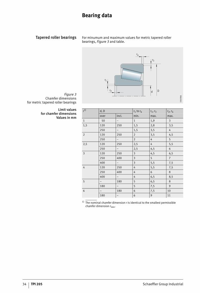
Tapered roller bearings For minumum and maximum values for metric tapered roller bearings, Figure 3 and table.
Limit valuesfor chamfer dimensions
Values in mm
1) The nominal chamfer dimension r is identical to the smallest permissible chamfer dimension rmin.
Figure 3Chamfer dimensions
for metric tapered roller bearings
d D
r4
r3
r1
r2
156
846
r1) d, D r1 to r4 r1, r3 r2, r4
over incl. min. max. max.
1 50 – 1 1,9 3
1,5 120 250 1,5 2,8 3,5
250 – 1,5 3,5 4
2 120 250 2 3,5 4,5
250 – 2 4 5
2,5 120 250 2,5 4 5,5
250 – 2,5 4,5 6
3 120 250 3 4,5 6,5
250 400 3 5 7
400 – 3 5,5 7,5
4 120 250 4 5,5 7,5
250 400 4 6 8
400 – 4 6,5 8,5
5 – 180 5 6,5 8
180 – 5 7,5 9
6 – 180 6 7,5 10
180 – 6 9 11
Schaeffler Group Industrial TPI 205 35
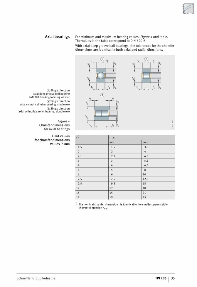
Axial bearings For minimum and maximum bearing values, Figure 4 and table.The values in the table correspond to DIN 620-6.With axial deep groove ball bearings, the tolerances for the chamfer dimensions are identical in both axial and radial directions.
Limit valuesfor chamfer dimensions
Values in mm
1) The nominal chamfer dimension r is identical to the smallest permissible chamfer dimension rmin.
� Single directionaxial deep groove ball bearing
with flat housing locating washer� Single direction
axial cylindrical roller bearing, single row� Single direction
axial cylindrical roller bearing, double row
Figure 4Chamfer dimensions
for axial bearings
r2
r1
r1 r1r2r2
r1 r1r2r2
r1 r1 r2r2
r1 r2
r2
r1 r1 r2
r2
r1 r1 r2
1
3
2
0001
776A
r1) r1, r2
min. max.
1,5 1,5 3,5
2 2 4
2,1 2,1 4,5
3 3 5,5
4 4 6,5
5 5 8
6 6 10
7,5 7,5 12,5
9,5 9,5 15
12 12 18
15 15 21
19 19 25
36 TPI 205 Schaeffler Group Industrial
Design of bearing arrangements
Adjacent construction In order to make full use of the accuracy and rigidity of the bearings in the machine, it must be ensured that the adjacent constructionis not only accurate but also has adequate rigidity and load carrying capacity. Particular attention must be paid to the introductionof potentially high axial loads. It is recommended that rigid, geometrically stable abutment is provided in the direction ofthe machine bed mounting points.
Shaft and housing tolerances The fit is derived from the ISO tolerances for the shaft andhousing (ISO 286) in conjunction with the bore tolerance dmp and the outside diameter tolerance Dmp of the bearings (DIN 620).
Reference to tables of shaftand housing tolerances
The recommendations for selection of shaft and housing tolerances are valid for normal mounting and operating conditions, see tables, page 37.
Schaeffler Group Industrial TPI 205 37
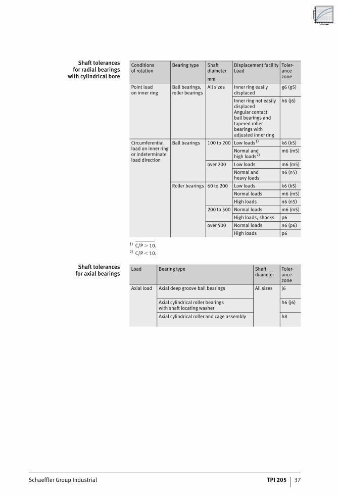
Shaft tolerancesfor radial bearings
with cylindrical bore
1) C/P 10.2) C/P � 10.
Shaft tolerancesfor axial bearings
Conditionsof rotation
Bearing type Shaft diameter
Displacement facilityLoad
Toler-ance zonemm
Point loadon inner ring
Ball bearings,roller bearings
All sizes Inner ring easily displaced
g6 (g5)
Inner ring not easily displacedAngular contactball bearings and tapered roller bearings with adjusted inner ring
h6 (j6)
Circumferential load on inner ring or indeterminate load direction
Ball bearings 100 to 200 Low loads1) k6 (k5)
Normal andhigh loads2)
m6 (m5)
over 200 Low loads m6 (m5)
Normal andheavy loads
n6 (n5)
Roller bearings 60 to 200 Low loads k6 (k5)
Normal loads m6 (m5)
High loads n6 (n5)
200 to 500 Normal loads m6 (m5)
High loads, shocks p6
over 500 Normal loads n6 (p6)
High loads p6
Load Bearing type Shaft diameter
Toler-ance zone
Axial load Axial deep groove ball bearings All sizes j6
Axial cylindrical roller bearingswith shaft locating washer
h6 (j6)
Axial cylindrical roller and cage assembly h8
38 TPI 205 Schaeffler Group Industrial
Design of bearing arrangements
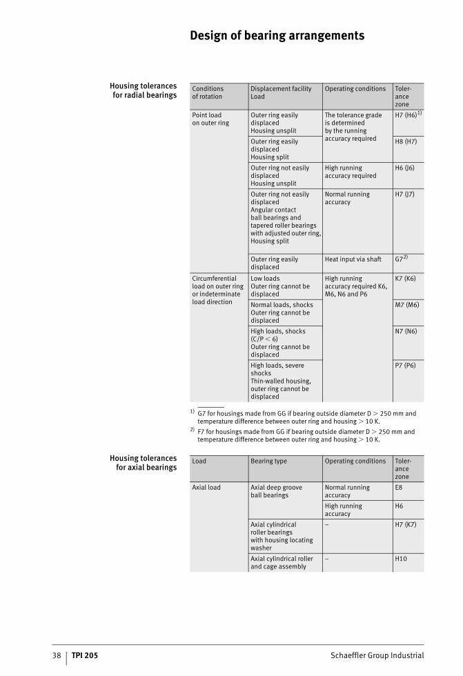
Housing tolerancesfor radial bearings
1) G7 for housings made from GG if bearing outside diameter D 250 mm and temperature difference between outer ring and housing 10 K.
2) F7 for housings made from GG if bearing outside diameter D 250 mm and temperature difference between outer ring and housing 10 K.
Housing tolerancesfor axial bearings
Conditionsof rotation
Displacement facilityLoad
Operating conditions Toler-ance zone
Point loadon outer ring
Outer ring easily displacedHousing unsplit
The tolerance gradeis determinedby the runningaccuracy required
H7 (H6)1)
Outer ring easily displacedHousing split
H8 (H7)
Outer ring not easily displacedHousing unsplit
High runningaccuracy required
H6 (J6)
Outer ring not easily displacedAngular contactball bearings and tapered roller bearings with adjusted outer ring, Housing split
Normal runningaccuracy
H7 (J7)
Outer ring easily displaced
Heat input via shaft G72)
Circumferential load on outer ring or indeterminate load direction
Low loadsOuter ring cannot be displaced
High runningaccuracy required K6,M6, N6 and P6
K7 (K6)
Normal loads, shocks Outer ring cannot be displaced
M7 (M6)
High loads, shocks (C/P � 6)Outer ring cannot be displaced
N7 (N6)
High loads, severe shocksThin-walled housing, outer ring cannot be displaced
P7 (P6)
Load Bearing type Operating conditions Toler-ance zone
Axial load Axial deep grooveball bearings
Normal running accuracy
E8
High runningaccuracy
H6
Axial cylindricalroller bearingswith housing locating washer
– H7 (K7)
Axial cylindrical roller and cage assembly
– H10
Schaeffler Group Industrial TPI 205 39
Mounting
It must be ensured that, at the time of mounting, adequate lubrication of the rolling contact is already present. The adjacent construction must be checked for the necessary accuracy.For support during initial mounting, we recommend that youconsult our experts in Industrial Service, see section Equipment and services for the mounting and maintenance of rolling bearings, page 146.
One-bearing solutions In one-bearing solutions, a distinction is drawn between the high precision bearings YRTS and ZKLDF of compact design andthe solution using crossed roller bearings as presented in this TPI.
High precision bearings The mounting of high precision bearings in accordance with TPI 120 is described in TPI 103, High Precision Bearings for Combined Loads.
Crossed roller bearings Crossed roller bearings Z-556 are supplied already set to a defined axial preload. In the case of crossed roller bearings Z-549, the axial preload is set during mounting.
Two-bearing solutions During mounting, it must be ensured that there is good radial running on the one hand between the axial deep groove ball bearing and the angular contact bearing. This can be achieved eitherby means of the centring devices or by appropriate alignmentof the axial washers. On the other hand, the axial preload must be set correctly by means of the angular contact bearing.
Three-bearing solutions Good radial running of the axial deep groove ball bearing in relation to the radial cylindrical roller bearing must be ensured. This can be carried out either by means of the centring device or an alignment operation. The radial cylindrical roller bearing must be mounted in accordance with the specified radial preload, see Catalogue SP 1, Super Precision Bearings. Preloading of the axial bearings must be carried out with particular care.

40 TPI 205 Schaeffler Group Industrial
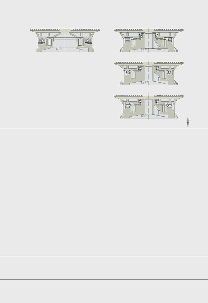
Bearing solutionsOne-bearing solutionsTwo-bearing solutions
Three-bearing solutions
42 TPI 205 Schaeffler Group Industrial
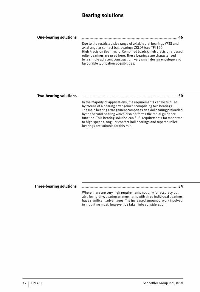
Bearing solutions
One-bearing solutions .................................................................................................................... 46Due to the restricted size range of axial/radial bearings YRTS and axial angular contact ball bearings ZKLDF (see TPI 120,High Precision Bearings for Combined Loads), high precision crossed roller bearings are used here. These bearings are characterisedby a simple adjacent construction, very small design envelope and favourable lubrication possibilities.
Two-bearing solutions .................................................................................................................... 50In the majority of applications, the requirements can be fulfilledby means of a bearing arrangement comprising two bearings.The main bearing arrangement comprises an axial bearing preloaded by the second bearing which also performs the radial guidance function. This bearing solution can fulfil requirements for moderate to high speeds. Angular contact ball bearings and tapered roller bearings are suitable for this role.
Three-bearing solutions .................................................................................................................... 54Where there are very high requirements not only for accuracy but also for rigidity, bearing arrangements with three individual bearings have significant advantages. The increased amount of work involved in mounting must, however, be taken into consideration.
Schaeffler Group Industrial TPI 205 43
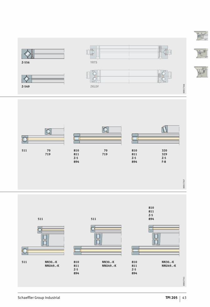
Z-556
Z-549
YRTS
ZKLDF
0001
7346
511 70719
810811Z-5894
810811Z-5894
320329Z-5F-8
70719
0001
7347
511 NN30..-KNNU49..-K
511 511
810811Z-5894
810811Z-5894
810811Z-5894
NN30..-KNNU49..-K
NN30..-KNNU49..-K
0001
7741
44 TPI 205 Schaeffler Group Industrial
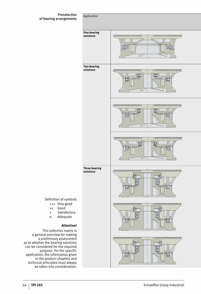
Preselectionof bearing arrangements
Definition of symbols+++ Very good++ Good+ Satisfactoryo Adequate
Attention!This selection matrix is
a general overview for makinga preliminary assessment
as to whether the bearing solutionscan be considered for the required
purpose. For the specificapplication, the information given
in the product chapters andtechnical principles must always
be taken into consideration.
Application
One-bearing solutions
Two-bearing solutions
Three-bearing solutions
Schaeffler Group Industrial TPI 205 45
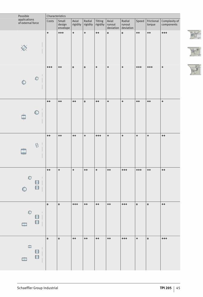
Possibleapplicationsof external force
Characteristics
Costs Small design envelope
Axial rigidity
Radial rigidity
Tilting rigidity
Axialrunout deviation
Radial runout deviation
Speed Frictional torque
Complexity of components
+ +++ + + ++ o o ++ ++ +++
+++ ++ o o + + + +++ +++ +
++ ++ ++ o ++ + + ++ ++ +
++ ++ ++ + +++ + + + + ++
++ + + ++ + ++ +++ +++ ++ ++
o o +++ ++ ++ ++ +++ o o ++
o o ++ ++ ++ ++ +++ + o +++
One-bearing solutions
Schaeffler Group Industrial TPI 205 47
Page
One-bearing solutions
Product overview One-bearing solutions ............................................................... 48
Features Crossed roller bearings.............................................................. 49
Higher running accuracy ............................................................ 49
48 TPI 205 Schaeffler Group Industrial
Product overview One-bearing solutions
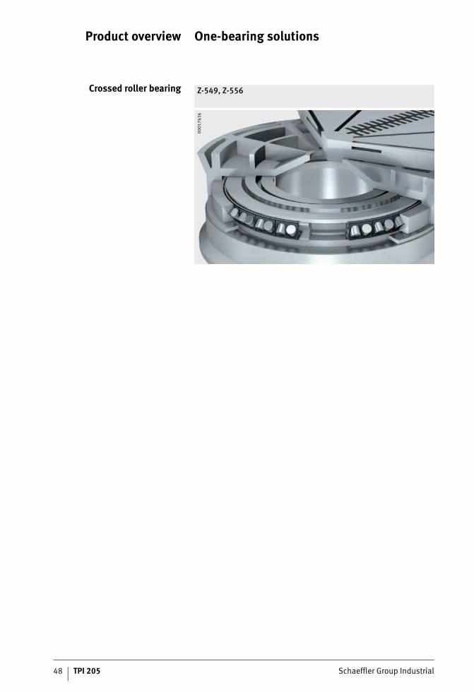
Crossed roller bearing Z-549, Z-556
0001
7636
Schaeffler Group Industrial TPI 205 49
One-bearing solutions
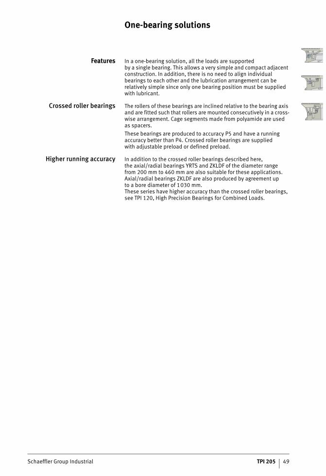
Features In a one-bearing solution, all the loads are supportedby a single bearing. This allows a very simple and compact adjacent construction. In addition, there is no need to align individual bearings to each other and the lubrication arrangement can be relatively simple since only one bearing position must be supplied with lubricant.
Crossed roller bearings The rollers of these bearings are inclined relative to the bearing axis and are fitted such that rollers are mounted consecutively in a cross-wise arrangement. Cage segments made from polyamide are usedas spacers.These bearings are produced to accuracy P5 and have a running accuracy better than P4. Crossed roller bearings are suppliedwith adjustable preload or defined preload.
Higher running accuracy In addition to the crossed roller bearings described here,the axial/radial bearings YRTS and ZKLDF of the diameter rangefrom 200 mm to 460 mm are also suitable for these applications. Axial/radial bearings ZKLDF are also produced by agreement upto a bore diameter of 1030 mm.These series have higher accuracy than the crossed roller bearings, see TPI 120, High Precision Bearings for Combined Loads.
Two-bearing solutions
Schaeffler Group Industrial TPI 205 51
Page
Two-bearing solutions
Product overview Two-bearing solutions ............................................................... 52
Features Speeds...................................................................................... 53
Accuracy Dimensional and geometrical tolerances.................................... 53
52 TPI 205 Schaeffler Group Industrial
Product overview Two-bearing solutions
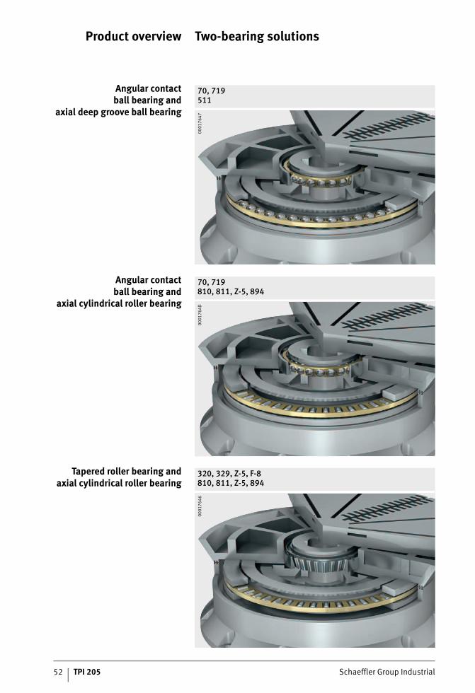
Angular contactball bearing and
axial deep groove ball bearing
70, 719511
0001
7647
Angular contactball bearing and
axial cylindrical roller bearing
70, 719810, 811, Z-5, 894
0001
764D
Tapered roller bearing andaxial cylindrical roller bearing
320, 329, Z-5, F-8810, 811, Z-5, 894
0001
7646
Schaeffler Group Industrial TPI 205 53
Two-bearing solutions
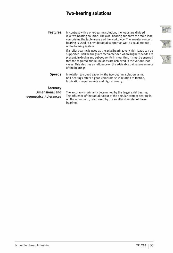
Features In contrast with a one-bearing solution, the loads are dividedin a two-bearing solution. The axial bearing supports the main load comprising the table mass and the workpiece. The angular contact bearing is used to provide radial support as well as axial preloadof the bearing system.If a roller bearing is used as the axial bearing, very high loads can be supported. Ball bearings are recommended where higher speeds are present. In design and subsequently in mounting, it must be ensured that the required minimum loads are achieved in the various load cases. This also has an influence on the advisable pair arrangements of the bearings.
Speeds In relation to speed capacity, the two-bearing solution usingball bearings offers a good compromise in relation to friction, lubrication requirements and high accuracy.
AccuracyDimensional and
geometrical tolerancesThe accuracy is primarily determined by the larger axial bearing.The influence of the radial runout of the angular contact bearing is, on the other hand, relativised by the smaller diameter of these bearings.
Three-bearing solutions

Schaeffler Group Industrial TPI 205 55
Page
Three-bearing solutions
Product overview Three-bearing solutions ............................................................. 56
Features Lubrication................................................................................ 57
Rigidity...................................................................................... 57
Accuracy Dimensional and geometrical tolerances.................................... 57
56 TPI 205 Schaeffler Group Industrial
Product overview Three-bearing solutions
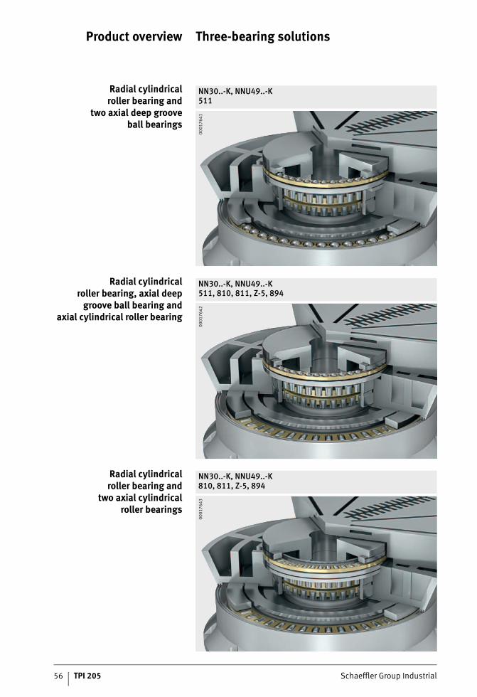
Radial cylindricalroller bearing and
two axial deep grooveball bearings
NN30..-K, NNU49..-K511
0001
7641
Radial cylindricalroller bearing, axial deep
groove ball bearing andaxial cylindrical roller bearing
NN30..-K, NNU49..-K511, 810, 811, Z-5, 894
0001
7642
Radial cylindricalroller bearing and
two axial cylindricalroller bearings
NN30..-K, NNU49..-K810, 811, Z-5, 894
0001
7643
Schaeffler Group Industrial TPI 205 57
Three-bearing solutions
Features In this arrangement, the combined loads are divided as appropriate over the two axial bearings and the radial bearing. This allows separate consideration in design work. Selection of the preload to ensure the minimum loads in the axial rows must be determinedin accordance with the load cases.
Lubrication Particular care must be taken on lubrication. While the axial bearings require higher oil throughput for heat dissipation, this is not necessary with the higher speeds occurring in the radial cylindrical roller bearing. Due to the design, the radial bearing can in most cases be supplied with the oil from the smaller axial bearing located above, see page 124.
Rigidity High rigidity of the bearing system can be achieved by definedaxial preloading of the two axial bearings relative to each otherin addition to radial preloading of the radial bearing to 5 �m,see page 126 and Catalogue SP 1, Super Precision Bearings.
AccuracyDimensional and
geometrical tolerancesIf the individual bearings are correctly combined, this bearing arrangement allows the very highest accuracy to be achieved.
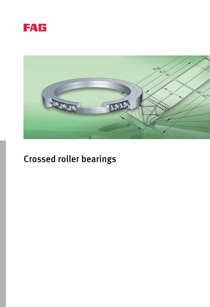
Crossed roller bearings
Schaeffler Group Industrial TPI 205 59
Page
Crossed roller bearings
Product overview Crossed roller bearings.............................................................. 60
Features For axial, radial and moment loads ............................................ 61
Limiting speed........................................................................... 62
Preload ..................................................................................... 62
Rigidity...................................................................................... 64
Sealing...................................................................................... 64
Lubrication................................................................................ 65
Operating temperature .............................................................. 66
Design andsafety guidelines
Checking the static load safety factor......................................... 67
Safety factors ............................................................................ 67
Calculation of the rating life ....................................................... 67
Shaft and housing tolerances .................................................... 71
Location using clamping rings.................................................... 73
Fixing screws............................................................................. 73
Securing of screws..................................................................... 73
Fitting of crossed roller bearings ................................................ 74
Checking operation ................................................................... 74
Accuracy Bearings in metric sizes ............................................................. 75
Bearings in inch sizes ................................................................ 76
Dimension tables Crossed roller bearings, adjustable preload,metric sizes and inch sizes ........................................................ 78
Crossed roller bearings, specified and defined preload,metric sizes and inch sizes ........................................................ 80
60 TPI 205 Schaeffler Group Industrial
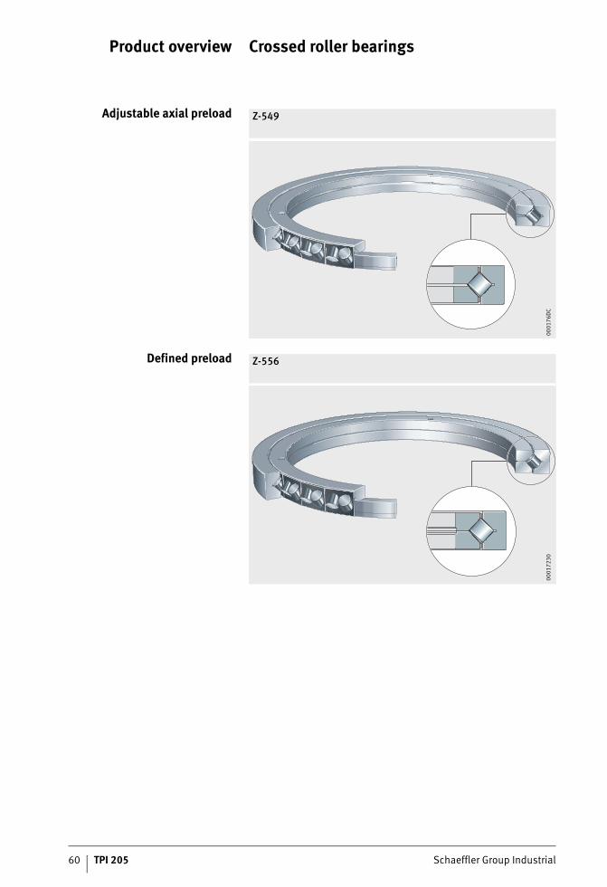
Product overview Crossed roller bearings
Adjustable axial preload Z-549
0001
76D
C
Defined preload Z-556
0001
7230
Schaeffler Group Industrial TPI 205 61
Crossed roller bearings
Features Crossed roller bearings are highly rigid, have a running accuracy better than P4 and the remaining tolerances to P5, and are preloaded.The bearing outer rings are easily fixed to the adjacent construction using clamping rings.The crossed roller bearings described here have a special internal construction that is designed for higher speeds and are optimised for use in vertical turret lathes. In comparison with the bearings described in TPI 120, High Precision Bearings for Combined Loads, crossed roller bearings of the same size can offer a significantly higher basic dynamic load rating. Due to the smaller numberof rolling elements, they have reduced rigidity.The guidelines and values in this chapter relate only to the crossed roller bearings listed in the tables.The bearings are operated with a rotating outer ring.
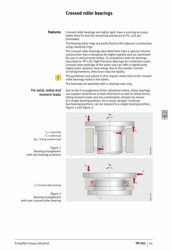
For axial, radial andmoment loads
Due to the O arrangement of the cylindrical rollers, these bearings can support axial forces in both directions as well as radial forces, tilting moment loads and any combination of loads by meansof a single bearing position. As a result, designs involvingtwo bearing positions can be reduced to a single bearing position, Figure 1 and Figure 2.
Fa = axial loadFr = radial load
Mk = tilting moment load
Figure 1Bearing arrangement
with two bearing positions
Fa
Mk
Fa
Fr
Fr
0001
7B7C
� Crossed roller bearing
Figure 2Bearing arrangement
with one crossed roller bearing
Mk
Fr
Fa
Fa
1
0001
7210
62 TPI 205 Schaeffler Group Industrial
Crossed roller bearings
Limiting speed The limiting speed is dependent on the lubrication (grease or oil), see dimension tables.If other limiting speeds are required, please contact the engineering service of the Schaeffler Group.
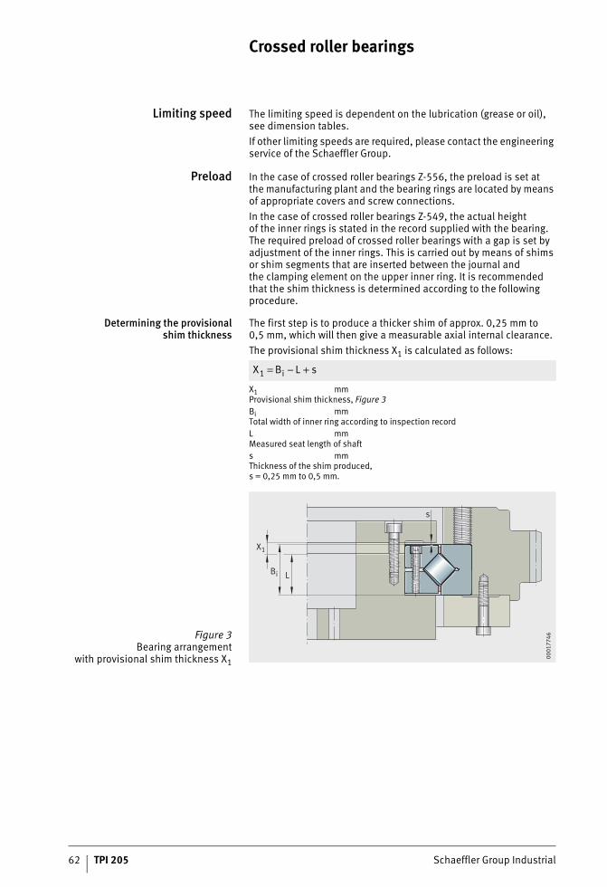
Preload In the case of crossed roller bearings Z-556, the preload is set atthe manufacturing plant and the bearing rings are located by means of appropriate covers and screw connections.In the case of crossed roller bearings Z-549, the actual heightof the inner rings is stated in the record supplied with the bearing. The required preload of crossed roller bearings with a gap is set by adjustment of the inner rings. This is carried out by means of shims or shim segments that are inserted between the journal andthe clamping element on the upper inner ring. It is recommended that the shim thickness is determined according to the following procedure.
Determining the provisionalshim thickness
The first step is to produce a thicker shim of approx. 0,25 mm to 0,5 mm, which will then give a measurable axial internal clearance.The provisional shim thickness X1 is calculated as follows:
X1 mmProvisional shim thickness, Figure 3Bi mmTotal width of inner ring according to inspection recordL mmMeasured seat length of shafts mmThickness of the shim produced,s = 0,25 mm to 0,5 mm.
X B L si1 = − +
Figure 3Bearing arrangement
with provisional shim thickness X1
L
s
X1
Bi
0001
7746
Schaeffler Group Industrial TPI 205 63
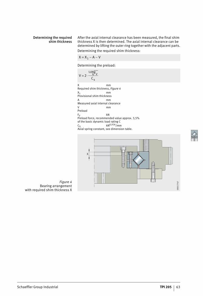
Determining the requiredshim thickness
After the axial internal clearance has been measured, the final shim thickness X is then determined. The axial internal clearance can be determined by lifting the outer ring together with the adjacent parts.Determining the required shim thickness:
Determining the preload:
X mmRequired shim thickness, Figure 4X1 mmProvisional shim thicknessA mmMeasured axial internal clearanceV mmPreloadFV kNPreload force, recommended value approx. 3,5%of the basic dynamic load rating CCS kN0,926/mmAxial spring constant, see dimension table.
X X A V= − −1
VF
CV
s= ⋅2
1 08,
Figure 4Bearing arrangement
with required shim thickness X
X
0001
7747
64 TPI 205 Schaeffler Group Industrial
Crossed roller bearings
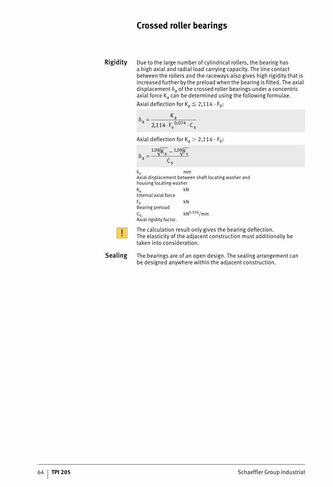
Rigidity Due to the large number of cylindrical rollers, the bearing hasa high axial and radial load carrying capacity. The line contact between the rollers and the raceways also gives high rigidity that is increased further by the preload when the bearing is fitted. The axial displacement �a of the crossed roller bearings under a concentric axial force Ka can be determined using the following formulae.Axial deflection for Ka � 2,114 · FV:
Axial deflection for Ka 2,114 · FV:
�a mmAxial displacement between shaft locating washer andhousing locating washerKa kNInternal axial forceFV kNBearing preloadCS kN0,926/mmAxial rigidity factor.
The calculation result only gives the bearing deflection.The elasticity of the adjacent construction must additionally be taken into consideration.
Sealing The bearings are of an open design. The sealing arrangement canbe designed anywhere within the adjacent construction.
�aa
v s
K
F C=
⋅ ⋅2 114 0 074, ,
�aa v
s
K FC
=−1 08 1 08, ,
Schaeffler Group Industrial TPI 205 65
Lubrication The crossed roller bearings can be lubricated with oil or grease.
Grease lubrication For grease lubrication, a high quality lithium soap grease KP2N–20 to DIN 51825 is suitable, such as Arcanol MULTITOP.For low speeds, and especially for horizontal axes, the simple grease lubrication method should be used. In vertical axes with grease lubrication, a baffle plate should be fitted under the bearing to minimise the escape of grease. We recommend the use of a grease with a lithium soap base and EP additives. When initial greasingis carried out, the space between the rollers should be filled with grease. A relubrication quantity of 20% to 30% of the initial grease quantity is recommended.
Oil lubrication For oil lubrication, oils CLP to DIN 51517 or HLP to DIN 51524of viscosity classes ISO VG 46 to ISO VG 68 are suitable.
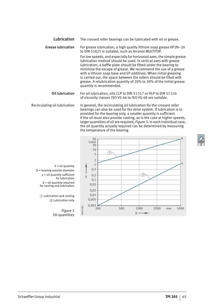
Recirculating oil lubrication In general, the recirculating oil lubrication for the crossed roller bearings can also be used for the drive system. If lubrication is to provided for the bearing only, a smaller quantity is sufficient.If the oil must also provide cooling, as is the case at higher speeds, larger quantities of oil are required, Figure 5. In each individual case, the oil quantity actually required can be determined by measuring the temperature of the bearing.
V = oil quantityD = bearing outside diameter
a = oil quantity sufficientfor lubrication
b = oil quantity requiredfor cooling and lubrication
� Lubrication and cooling� Lubrication only
Figure 5Oil quantities
50l/min
2010
5
21
0,5
0,20,1
0,05
0,020,01
0,005
0,002200 500 1 000 2 000 5 000mm
D
V.
1
2
a
b
0001
73B2
66 TPI 205 Schaeffler Group Industrial
Crossed roller bearings
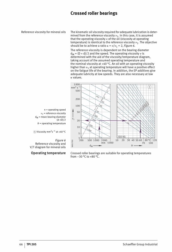
Reference viscosity for mineral oils The kinematic oil viscosity required for adequate lubrication is deter-mined from the reference viscosity �1. In this case, it is assumedthat the operating viscosity � of the oil (viscosity at operating temperature) is identical to the reference viscosity �1. The objective should be to achieve a ratio � = �/�1 = 2, Figure 6.The reference viscosity is dependent on the bearing diameter dM = (D + d)/2 and the speed. The operating viscosity � is determined with the aid of the viscosity/temperature diagram,taking account of the assumed operating temperature andthe nominal viscosity at +40 °C. An oil with an operating viscosity higher than �1 at operating temperature will have a positive effecton the fatigue life of the bearing. In addition, the EP additives give adequate lubricity at low speeds. They are also necessary at low � values.
Operating temperature Crossed roller bearings are suitable for operating temperaturesfrom –30 °C to +80 °C.
n = operating speed�1 = reference viscosity
dM = mean bearing diameter(d +D)/2
� = operating temperature
� Viscosity mm2s–1 at +40 °C
Figure 6Reference viscosity and
V/T diagram for mineral oils5000
200 500 1000 2000
mm2 s–1
�1
3
5
10
20
50
100
200
500
1000
mm
1000
500
200
100
50
20
10
5
2
1
nmin –1
dM �
10 20 30 40 50 6070
80100
120°CISO VG
1015
2232
4668
100150
220320
460680
10001500
1
0001
7781
Schaeffler Group Industrial TPI 205 67
Design andsafety guidelines
Checking the static loadsafety factor
The static load safety factor can be checked in approximate termsif the load arrangement is present and all the requirements relating to clamping rings, location, fitting and lubrication are fulfilled, Figure 2, page 61.In order to check the static load carrying capacity, the following equivalent static operating values must be determined:■ bearing load F0q■ tilting moment load M0q.Checking is possible for applications with or without radial load.Where load arrangements are more complex or the conditions are not fulfilled, please contact us.
Safety factors For smooth running, the objective should be a factor fS � 4,see page 11.
Calculation of the rating life The methods for calculating the rating life are:■ the basic rating life L10 and L10h to ISO 281, see page 12■ the simplified form of rating life calculation based on empirical
values, see page 68.
Validity The rating life formulae for L and Lh are only valid:■ with a load arrangement in accordance with Figure 2, page 61■ if all the requirements are fulfilled in relation to location
(the bearing rings must be rigid or firmly connected tothe adjacent construction), fitting, lubrication and sealing
■ if the load and speed in the duty cycle can be regardedas constant during operation.
68 TPI 205 Schaeffler Group Industrial
Crossed roller bearings
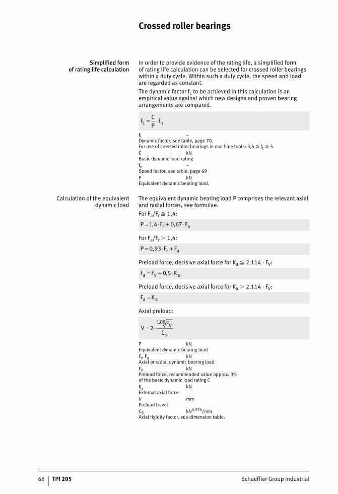
Simplified formof rating life calculation
In order to provide evidence of the rating life, a simplified formof rating life calculation can be selected for crossed roller bearings within a duty cycle. Within such a duty cycle, the speed and loadare regarded as constant.The dynamic factor fL to be achieved in this calculation is an empirical value against which new designs and proven bearing arrangements are compared.
fL –Dynamic factor, see table, page 70.For use of crossed roller bearings in machine tools: 3,5 � fL � 5C kNBasic dynamic load ratingfn –Speed factor, see table, page 69P kNEquivalent dynamic bearing load.
Calculation of the equivalentdynamic load
The equivalent dynamic bearing load P comprises the relevant axial and radial forces, see formulae.For Fa/Fr � 1,4:
For Fa/Fr 1,4:
Preload force, decisive axial force for Ka � 2,114 · FV:
Preload force, decisive axial force for Ka 2,114 · FV:
Axial preload:
P kNEquivalent dynamic bearing loadFr, Fa kNAxial or radial dynamic bearing loadFV kNPreload force, recommended value approx. 3%of the basic dynamic load rating CKa kNExternal axial forceV mmPreload travelCS kN0,926/mmAxial rigidity factor, see dimension table.
fCP
fL n= ⋅
P F Fr a= ⋅ + ⋅1 4 0 67, ,
P F Fr a= ⋅ +0 93,
F F Ka v a= + ⋅0 5,
F Ka a=
VF
CV
s= ⋅2
1 08,
Schaeffler Group Industrial TPI 205 69
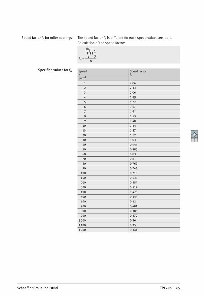
Speed factor fn for roller bearings The speed factor fn is different for each speed value, see table.Calculation of the speed factor:
Specified values for fn
fnn =33
13
103
Speedn
Speed factorfn
min–1
1 2,86
2 2,33
3 2,06
4 1,89
5 1,77
6 1,67
7 1,6
8 1,53
9 1,48
10 1,44
15 1,27
20 1,17
30 1,03
40 0,947
50 0,885
60 0,838
70 0,8
80 0,769
90 0,742
100 0,719
150 0,637
200 0,584
300 0,517
400 0,475
500 0,444
600 0,42
700 0,401
800 0,385
900 0,372
1 000 0,36
1 100 0,35
1 200 0,341
70 TPI 205 Schaeffler Group Industrial
Crossed roller bearings
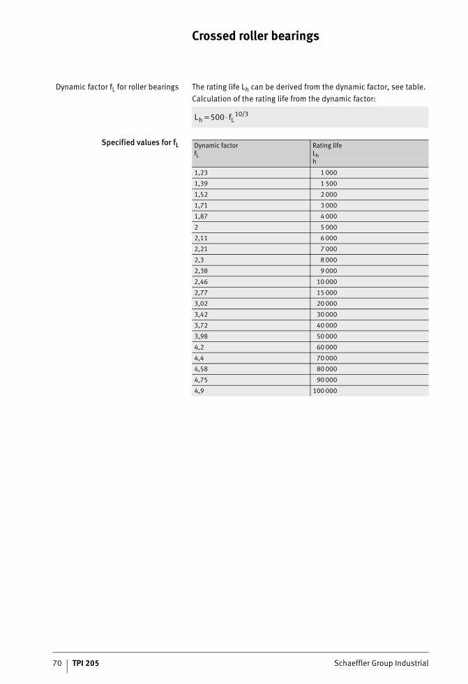
Dynamic factor fL for roller bearings The rating life Lh can be derived from the dynamic factor, see table.Calculation of the rating life from the dynamic factor:
Specified values for fL
L fh L= ⋅500 10 3/
Dynamic factorfL
Rating lifeLhh
1,23 1 000
1,39 1 500
1,52 2 000
1,71 3 000
1,87 4 000
2 5 000
2,11 6 000
2,21 7 000
2,3 8 000
2,38 9 000
2,46 10 000
2,77 15 000
3,02 20 000
3,42 30 000
3,72 40 000
3,98 50 000
4,2 60 000
4,4 70 000
4,58 80 000
4,75 90 000
4,9 100 000
Schaeffler Group Industrial TPI 205 71
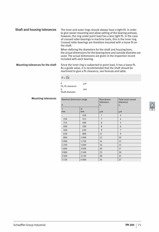
Shaft and housing tolerances The inner and outer rings should always have a tight fit. In orderto give easier mounting and allow setting of the bearing preload, however, the ring under point load has a less tight fit. In the caseof crossed roller bearings in machine tools, this is the inner ring. Crossed roller bearings are therefore mounted with a loose fit onthe shaft.When defining the diameters for the shaft and housing bore,the actual dimensions for the bearing bore and outside diameter are used. The actual dimensions are given in the inspection record included with each bearing.
Mounting tolerances for the shaft Since the inner ring is subjected to point load, it has a loose fit.As a guide value, it is recommended that the shaft should be machined to give a fit clearance, see formula and table.
P �mFit, fit clearanced mmShaft diameter.
Mounting tolerances
P d= 3
Nominal dimension range Roundness tolerance
Total axial runout tolerance
d t1 t2
�mm mm �m �m
– 250 7 4
250 315 7 4
315 400 8 5
400 500 8 6
500 630 9 7
630 800 11 9
800 1 000 12 10
1 000 1 250 14 12
1 250 1 600 16 13
1 600 2 000 20 17
2 000 2 500 23 20
2 500 3 150 28 23
3 150 4 000 34 27
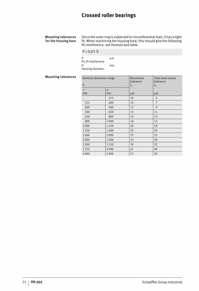
72 TPI 205 Schaeffler Group Industrial
Crossed roller bearings
Mounting tolerancesfor the housing bore
Since the outer ring is subjected to circumferential load, it has a tight fit. When machining the housing bore, this should give the following fit interference, see formula and table.
P �mFit, fit interferenceD mmHousing diameter.
Mounting tolerances
P D= ⋅0 03,
Nominal dimension range Roundness tolerance
Total axial runout tolerance
D t1 t2
�mm mm �m �m
– 315 10 6
315 400 12 7
400 500 12 9
500 630 13 11
630 800 15 13
800 1 000 18 15
1 000 1 250 20 18
1 250 1 600 23 20
1 600 2 000 27 25
2 000 2 500 33 30
2 500 3 150 39 35
3 150 4 000 47 40
4 000 5 000 57 50
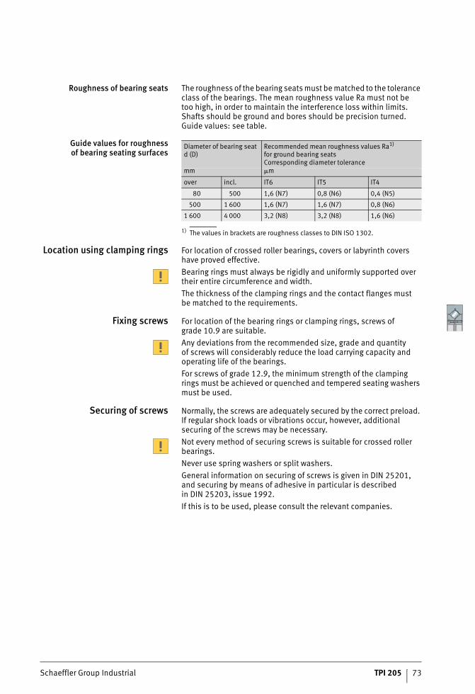
Schaeffler Group Industrial TPI 205 73
Roughness of bearing seats The roughness of the bearing seats must be matched to the tolerance class of the bearings. The mean roughness value Ra must not betoo high, in order to maintain the interference loss within limits.Shafts should be ground and bores should be precision turned. Guide values: see table.
Guide values for roughnessof bearing seating surfaces
1) The values in brackets are roughness classes to DIN ISO 1302.
Location using clamping rings For location of crossed roller bearings, covers or labyrinth covers have proved effective.Bearing rings must always be rigidly and uniformly supported over their entire circumference and width.The thickness of the clamping rings and the contact flanges mustbe matched to the requirements.
Fixing screws For location of the bearing rings or clamping rings, screws of grade 10.9 are suitable.Any deviations from the recommended size, grade and quantityof screws will considerably reduce the load carrying capacity and operating life of the bearings.For screws of grade 12.9, the minimum strength of the clamping rings must be achieved or quenched and tempered seating washers must be used.
Securing of screws Normally, the screws are adequately secured by the correct preload. If regular shock loads or vibrations occur, however, additional securing of the screws may be necessary.Not every method of securing screws is suitable for crossed roller bearings.Never use spring washers or split washers.General information on securing of screws is given in DIN 25201, and securing by means of adhesive in particular is describedin DIN 25203, issue 1992.If this is to be used, please consult the relevant companies.
Diameter of bearing seatd (D)
Recommended mean roughness values Ra1)
for ground bearing seatsCorresponding diameter tolerance
mm �m
over incl. IT6 IT5 IT4
80 500 1,6 (N7) 0,8 (N6) 0,4 (N5)
500 1 600 1,6 (N7) 1,6 (N7) 0,8 (N6)
1 600 4 000 3,2 (N8) 3,2 (N8) 1,6 (N6)
74 TPI 205 Schaeffler Group Industrial
Crossed roller bearings
Fitting of crossedroller bearings
The bores and edges of the adjacent components must be free from burrs. The support surfaces for the bearing rings must be clean.The seating and locating surfaces for the bearing rings on the adjacent construction must be lightly oiled or greased.Lightly oil the thread of the fixing screws in order to prevent varying friction factors (do not oil or grease screws that will be securedby means of adhesive).Ensure that all adjacent components and lubrication ducts are free from cleaning agents, solvents and washing emulsions.The bearing seating surfaces can rust or the raceway system can become contaminated.Mounting forces must only be applied to the bearing ring to be fitted; they must never be directed through the rolling elements or seals. Avoid direct blows on the bearing rings.Locate the bearing rings consecutively and without applicationof any external load.
Mounting The inner rings must be screwed together using the fixing screws for better transport. These must be loosened during mounting so that preload is no longer present. For easier handling during mounting and dismounting, one inner ring has three threaded holes for eye bolts.
Checking operation Once mounting is complete, the operation of the fitted crossed roller bearing must be checked.If the bearing runs irregularly or roughly, or the temperaturein the bearing shows an unusual increase, dismount and check the bearing and mount the bearing again in accordance with the fitting guidelines described.
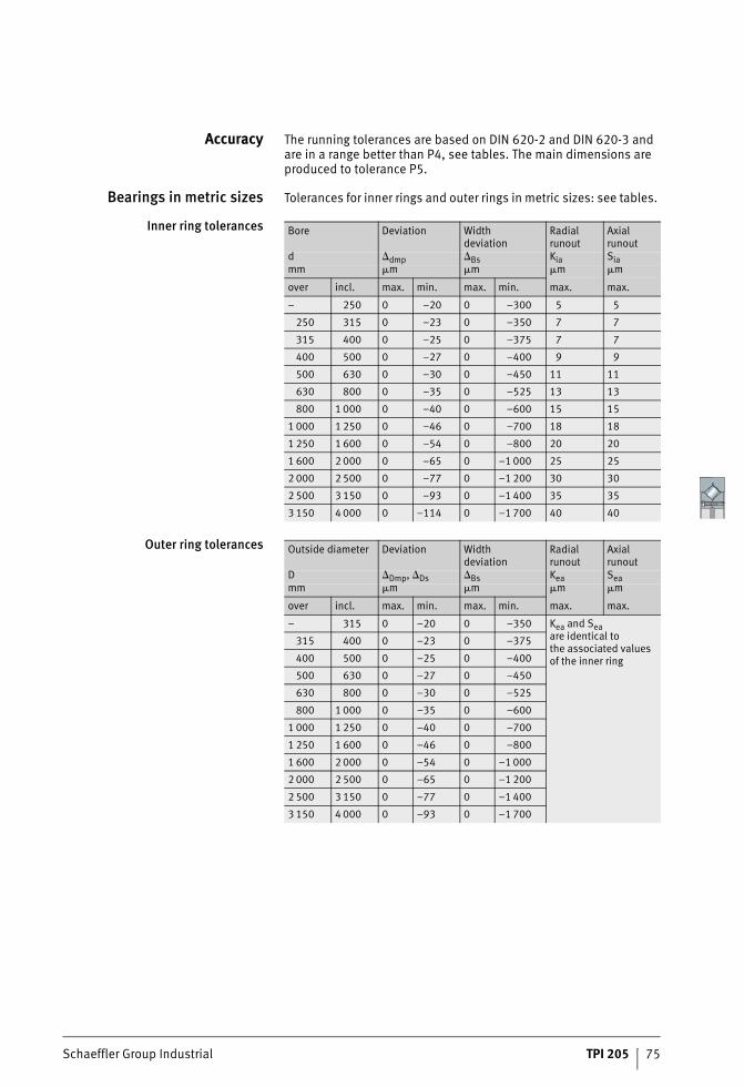
Schaeffler Group Industrial TPI 205 75
Accuracy The running tolerances are based on DIN 620-2 and DIN 620-3 and are in a range better than P4, see tables. The main dimensions are produced to tolerance P5.
Bearings in metric sizes Tolerances for inner rings and outer rings in metric sizes: see tables.
Inner ring tolerances
Outer ring tolerances
Bore Deviation Widthdeviation
Radial runout
Axial runout
d dmp Bs Kia Siamm �m �m �m �m
over incl. max. min. max. min. max. max.
– 250 0 –20 0 –300 5 5
250 315 0 –23 0 –350 7 7
315 400 0 –25 0 –375 7 7
400 500 0 –27 0 –400 9 9
500 630 0 –30 0 –450 11 11
630 800 0 –35 0 –525 13 13
800 1 000 0 –40 0 –600 15 15
1 000 1 250 0 –46 0 –700 18 18
1 250 1 600 0 –54 0 –800 20 20
1 600 2 000 0 –65 0 –1 000 25 25
2 000 2 500 0 –77 0 –1 200 30 30
2 500 3 150 0 –93 0 –1 400 35 35
3 150 4 000 0 –114 0 –1 700 40 40
Outside diameter Deviation Widthdeviation
Radial runout
Axial runout
D Dmp, Ds Bs Kea Seamm �m �m �m �m
over incl. max. min. max. min. max. max.
– 315 0 –20 0 –350 Kea and Seaare identical tothe associated values of the inner ring
315 400 0 –23 0 –375
400 500 0 –25 0 –400
500 630 0 –27 0 –450
630 800 0 –30 0 –525
800 1 000 0 –35 0 –600
1 000 1 250 0 –40 0 –700
1 250 1 600 0 –46 0 –800
1 600 2 000 0 –54 0 –1 000
2 000 2 500 0 –65 0 –1 200
2 500 3 150 0 –77 0 –1 400
3 150 4 000 0 –93 0 –1 700
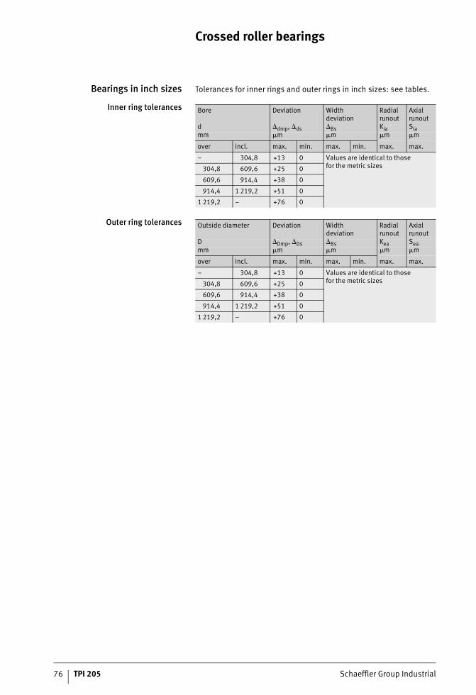
76 TPI 205 Schaeffler Group Industrial
Crossed roller bearings
Bearings in inch sizes Tolerances for inner rings and outer rings in inch sizes: see tables.
Inner ring tolerances
Outer ring tolerances
Bore Deviation Widthdeviation
Radial runout
Axial runout
d dmp, ds Bs Kia Siamm �m �m �m �m
over incl. max. min. max. min. max. max.
– 304,8 +13 0 Values are identical to thosefor the metric sizes304,8 609,6 +25 0
609,6 914,4 +38 0
914,4 1 219,2 +51 0
1 219,2 – +76 0
Outside diameter Deviation Widthdeviation
Radial runout
Axial runout
D Dmp, Ds Bs Kea Seamm �m �m �m �m
over incl. max. min. max. min. max. max.
– 304,8 +13 0 Values are identical to thosefor the metric sizes304,8 609,6 +25 0
609,6 914,4 +38 0
914,4 1 219,2 +51 0
1 219,2 – +76 0

Schaeffler Group Industrial TPI 205 77
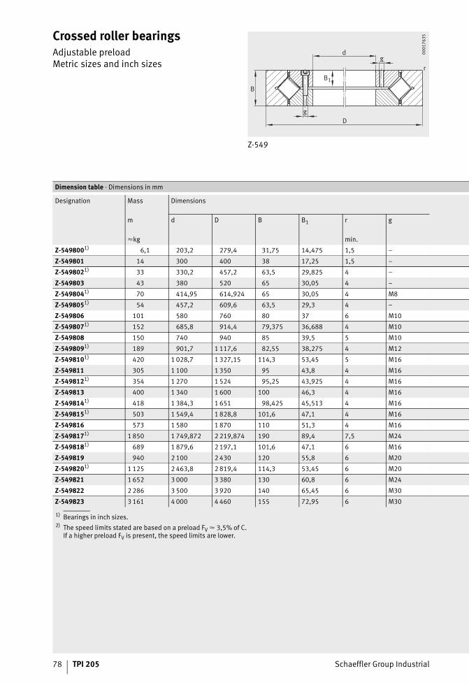
78 TPI 205 Schaeffler Group Industrial
Crossed roller bearingsAdjustable preloadMetric sizes and inch sizes
Z-549
r
D
d
g
g
B
B1
0001
7635
1) Bearings in inch sizes.2) The speed limits stated are based on a preload FV � 3,5% of C.
If a higher preload FV is present, the speed limits are lower.
Dimension table · Dimensions in mm
Designation Mass Dimensions
m d D B B1 r g
�kg min.
Z-5498001) 6,1 203,2 279,4 31,75 14,475 1,5 –
Z-549801 14 300 400 38 17,25 1,5 –
Z-5498021) 33 330,2 457,2 63,5 29,825 4 –
Z-549803 43 380 520 65 30,05 4 –
Z-5498041) 70 414,95 614,924 65 30,05 4 M8
Z-5498051) 54 457,2 609,6 63,5 29,3 4 –
Z-549806 101 580 760 80 37 6 M10
Z-5498071) 152 685,8 914,4 79,375 36,688 4 M10
Z-549808 150 740 940 85 39,5 5 M10
Z-5498091) 189 901,7 1 117,6 82,55 38,275 4 M12
Z-5498101) 420 1 028,7 1 327,15 114,3 53,45 5 M16
Z-549811 305 1 100 1 350 95 43,8 4 M16
Z-5498121) 354 1 270 1 524 95,25 43,925 4 M16
Z-549813 400 1 340 1 600 100 46,3 4 M16
Z-5498141) 418 1 384,3 1 651 98,425 45,513 4 M16
Z-5498151) 503 1 549,4 1 828,8 101,6 47,1 4 M16
Z-549816 573 1 580 1 870 110 51,3 4 M16
Z-5498171) 1 850 1 749,872 2 219,874 190 89,4 7,5 M24
Z-5498181) 689 1 879,6 2 197,1 101,6 47,1 6 M16
Z-549819 940 2 100 2 430 120 55,8 6 M20
Z-5498201) 1 125 2 463,8 2 819,4 114,3 53,45 6 M20
Z-549821 1 652 3 000 3 380 130 60,8 6 M24
Z-549822 2 286 3 500 3 920 140 65,45 6 M30
Z-549823 3 161 4 000 4 460 155 72,95 6 M30
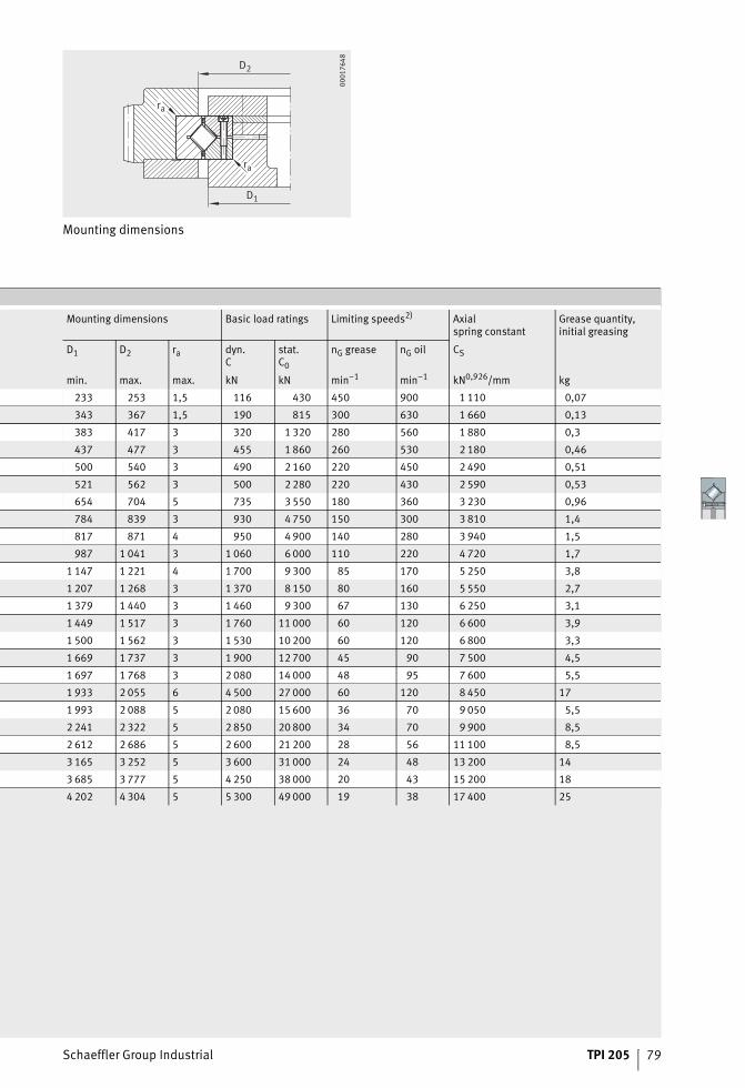
Schaeffler Group Industrial TPI 205 79
Mounting dimensions
ra
ra
D1
D2
0001
7648
Mounting dimensions Basic load ratings Limiting speeds2) Axialspring constant
Grease quantity,initial greasing
D1 D2 ra dyn.C
stat.C0
nG grease nG oil CS
min. max. max. kN kN min–1 min–1 kN0,926/mm kg
233 253 1,5 116 430 450 900 1 110 0,07
343 367 1,5 190 815 300 630 1 660 0,13
383 417 3 320 1 320 280 560 1 880 0,3
437 477 3 455 1 860 260 530 2 180 0,46
500 540 3 490 2 160 220 450 2 490 0,51
521 562 3 500 2 280 220 430 2 590 0,53
654 704 5 735 3 550 180 360 3 230 0,96
784 839 3 930 4 750 150 300 3 810 1,4
817 871 4 950 4 900 140 280 3 940 1,5
987 1 041 3 1 060 6 000 110 220 4 720 1,7
1 147 1 221 4 1 700 9 300 85 170 5 250 3,8
1 207 1 268 3 1 370 8 150 80 160 5 550 2,7
1 379 1 440 3 1 460 9 300 67 130 6 250 3,1
1 449 1 517 3 1 760 11 000 60 120 6 600 3,9
1 500 1 562 3 1 530 10 200 60 120 6 800 3,3
1 669 1 737 3 1 900 12 700 45 90 7 500 4,5
1 697 1 768 3 2 080 14 000 48 95 7 600 5,5
1 933 2 055 6 4 500 27 000 60 120 8 450 17
1 993 2 088 5 2 080 15 600 36 70 9 050 5,5
2 241 2 322 5 2 850 20 800 34 70 9 900 8,5
2 612 2 686 5 2 600 21 200 28 56 11 100 8,5
3 165 3 252 5 3 600 31 000 24 48 13 200 14
3 685 3 777 5 4 250 38 000 20 43 15 200 18
4 202 4 304 5 5 300 49 000 19 38 17 400 25
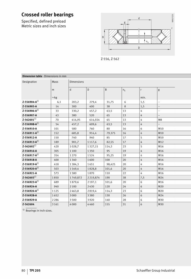
80 TPI 205 Schaeffler Group Industrial
Crossed roller bearingsSpecified, defined preloadMetric sizes and inch sizes
Z-556, Z-562
D
dg
ns
B
r
0001
7231
1) Bearings in inch sizes.
Dimension table · Dimensions in mm
Designation Mass Dimensions
m d D B ns r g
�kg min.
Z-556904-A1) 6,1 203,2 279,4 31,75 6 1,5 –
Z-556905-A 14 300 400 38 8 1,5 –
Z-556906-A1) 33 330,2 457,2 63,5 13 4 –
Z-556907-A 43 380 520 65 13 4 –
Z-5626011) 70 414,95 614,924 65 13 4 M8
Z-556908-A1) 54 457,2 609,6 63,5 13 4 –
Z-556910-A 101 580 760 80 16 6 M10
Z-556911-A1) 152 685,8 914,4 79,375 16 4 M10
Z-556912-A 150 740 940 85 17 5 M10
Z-556913-A1) 189 901,7 1 117,6 82,55 17 4 M12
Z-5626021) 420 1 028,7 1 327,15 114,3 23 5 M16
Z-556916-A 305 1 100 1 350 95 19 4 M16
Z-556917-A1) 354 1 270 1 524 95,25 19 4 M16
Z-556918-A 400 1 340 1 600 100 20 4 M16
Z-556919-A1) 418 1 384,3 1 651 98,425 20 4 M16
Z-556920-A1) 503 1 549,4 1 828,8 101,6 20 4 M16
Z-556921-A 573 1 580 1 870 110 22 4 M16
Z-5626031) 1 850 1 749,872 2 219,874 190 38 7,5 M24
Z-556923-A1) 689 1 879,6 2 197,1 101,6 20 6 M16
Z-556924-A 940 2 100 2 430 120 24 6 M20
Z-556926-A1) 1 125 2 463,8 2 819,4 114,3 23 6 M20
Z-556928-A 1 652 3 000 3 380 130 26 6 M24
Z-556929-A 2 286 3 500 3 920 140 28 6 M30
Z-562604 3 161 4 000 4 460 155 31 6 M30
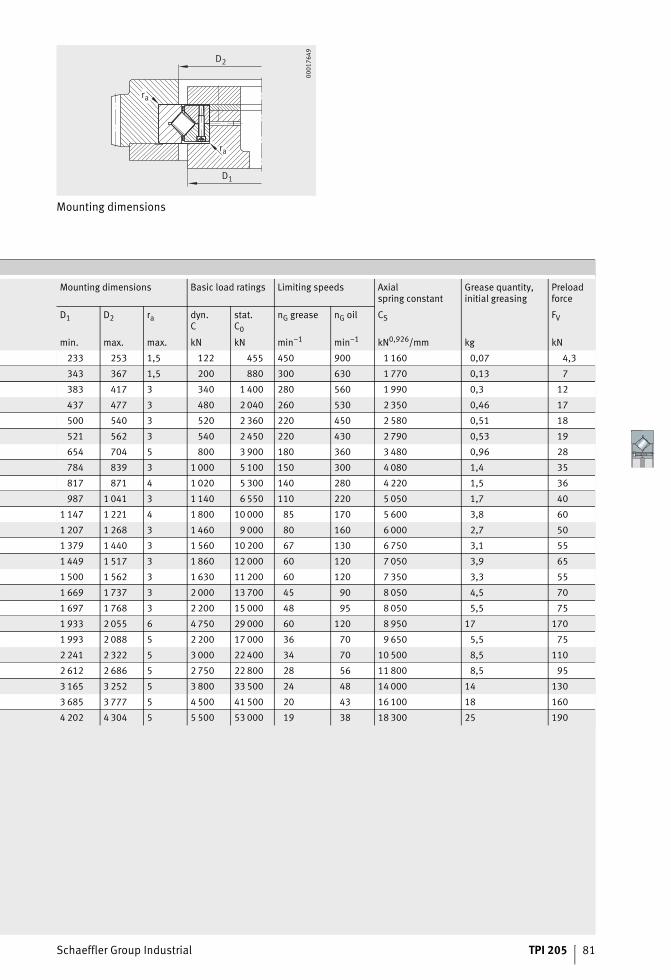
Schaeffler Group Industrial TPI 205 81
Mounting dimensions
ra
ra
D1
D2
0001
7649
Mounting dimensions Basic load ratings Limiting speeds Axialspring constant
Grease quantity,initial greasing
Preloadforce
D1 D2 ra dyn.C
stat.C0
nG grease nG oil CS FV
min. max. max. kN kN min–1 min–1 kN0,926/mm kg kN
233 253 1,5 122 455 450 900 1 160 0,07 4,3
343 367 1,5 200 880 300 630 1 770 0,13 7
383 417 3 340 1 400 280 560 1 990 0,3 12
437 477 3 480 2 040 260 530 2 350 0,46 17
500 540 3 520 2 360 220 450 2 580 0,51 18
521 562 3 540 2 450 220 430 2 790 0,53 19
654 704 5 800 3 900 180 360 3 480 0,96 28
784 839 3 1 000 5 100 150 300 4 080 1,4 35
817 871 4 1 020 5 300 140 280 4 220 1,5 36
987 1 041 3 1 140 6 550 110 220 5 050 1,7 40
1 147 1 221 4 1 800 10 000 85 170 5 600 3,8 60
1 207 1 268 3 1 460 9 000 80 160 6 000 2,7 50
1 379 1 440 3 1 560 10 200 67 130 6 750 3,1 55
1 449 1 517 3 1 860 12 000 60 120 7 050 3,9 65
1 500 1 562 3 1 630 11 200 60 120 7 350 3,3 55
1 669 1 737 3 2 000 13 700 45 90 8 050 4,5 70
1 697 1 768 3 2 200 15 000 48 95 8 050 5,5 75
1 933 2 055 6 4 750 29 000 60 120 8 950 17 170
1 993 2 088 5 2 200 17 000 36 70 9 650 5,5 75
2 241 2 322 5 3 000 22 400 34 70 10 500 8,5 110
2 612 2 686 5 2 750 22 800 28 56 11 800 8,5 95
3 165 3 252 5 3 800 33 500 24 48 14 000 14 130
3 685 3 777 5 4 500 41 500 20 43 16 100 18 160
4 202 4 304 5 5 500 53 000 19 38 18 300 25 190
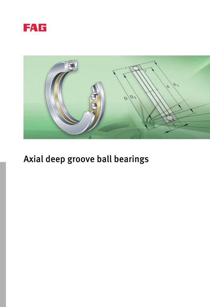
Axial deep groove ball bearings
Schaeffler Group Industrial TPI 205 83
Page
Axial deep groove ball bearings
Product overview Axial deep groove ball bearings ................................................. 84
Features Operating temperature .............................................................. 85
Cages........................................................................................ 85
Suffixes..................................................................................... 85
Ordering designation................................................................. 85
Design andsafety guidelines
Equivalent dynamic bearing load ............................................... 86
Equivalent static bearing load.................................................... 86
Minimum axial load ................................................................... 86
Speeds...................................................................................... 87
Design of bearing arrangements ................................................ 87
Accuracy Dimensional and geometrical tolerances.................................... 87
Dimension tables Axial deep groove ball bearings ................................................. 88
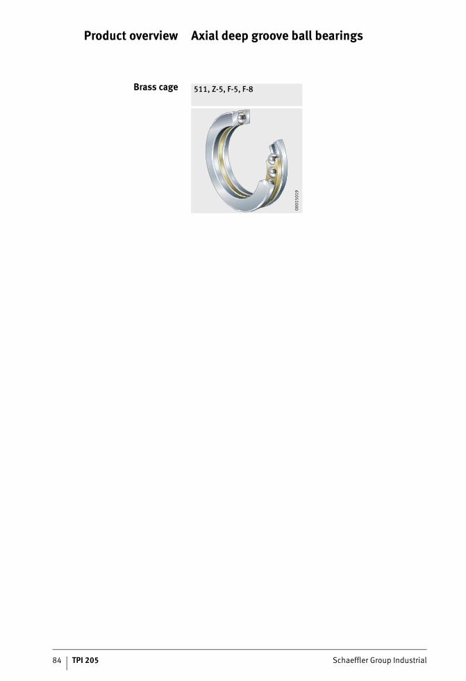
84 TPI 205 Schaeffler Group Industrial
Product overview Axial deep groove ball bearings
Brass cage 511, Z-5, F-5, F-8
0001
5019
Schaeffler Group Industrial TPI 205 85
Axial deep groove ball bearings
Features Axial deep groove ball bearings comprise a shaft locating washer,a housing locating washer and a ball and cage assembly.The bearings are not self-retaining; the ball and cage assembly and bearing washers can therefore be fitted separately.Single direction axial deep groove ball bearings can support axial forces in one direction, but must not be subjected to radial loads.
Operating temperature Axial deep groove ball bearings can be used at operating tempera-tures from –30 °C to +150 °C.
Cages Large axial deep groove ball bearings have ball-guided solid cages made from brass (suffix M or MP) or steel (suffix F or FP), see table.
Suffixes Suffixes for available designs: see table.
Available designs
Ordering designation Axial deep groove ball bearing with measurement record and marking of wall thick variation:
Suffix Description Design
F Solid steel cage, ball-guided Standard
FP Solid steel window cage, ball-guided
M Solid brass cage, ball-guided
MP Solid brass window cage, ball-guided
P5 Higher accuracy to tolerance class P5 Special design
MPB Solid brass window cage, washer-guided Special design,available by agreementM15 With measurement record
J15 Actual value indication, marking
J26 Marking of maximum wall thickness variation
■ 511/1320-MP-P5-J26CA-M15EZ– CA = shaft locating washer, housing locating washer– E = scope of measurements,
in this case including d, D, Si, Se– Z = measurement record included in packaging.
86 TPI 205 Schaeffler Group Industrial
Axial deep groove ball bearings
Design andsafety guidelines
Axial deep groove ball bearings can support axial forces only.For calculation of the complete bearing arrangement, advice should be sought from the engineering service of the Schaeffler Group.
Equivalent dynamicbearing load
For bearings under dynamic loading, the following applies:
P kNEquivalent dynamic bearing loadFa kNAxial dynamic bearing load.
Equivalent staticbearing load
For bearings under static loading, the following applies:
P0 kNEquivalent static bearing loadF0a kNAxial static bearing load.
Minimum axial load At higher speeds, detrimental sliding movements can occur between the rolling elements and the raceways due to centrifugal forces and gyroscopic moments. In order to prevent slippage, the bearings must be subjected to a minimum load Fa min.The minimum load factor A is given in the dimension table.For nmax, the maximum operating speed must be used.
Fa min kNMinimum axial loadA –Minimum load factor, see dimension tablenmax min–1
Maximum operating speed.
P Fa=
P F a0 0=
F An
a minmax= ⋅⎛
⎝⎜
⎞⎠⎟1000
2
Schaeffler Group Industrial TPI 205 87
Speeds ISO 15312 does not give thermal reference speeds for axial deep groove ball bearings.The dimension table gives limiting speeds for oil lubrication.
Design of bearingarrangements
In order to make comprehensive use of the performance capacityof the bearings, the adjacent construction must be of an appropriate design.
Shaft and housing tolerances For single direction bearings, the shaft tolerance j6 should be selected.The tolerance of the locating bore is dependent on the running accuracy to be achieved. For normal running accuracy, the tolerance should be in the tolerance zone E8, for high running accuracyit should be in the tolerance zone H6.Customer-specific solutions are available by agreement.
Adjacent parts The shoulders on the adjacent construction must be sufficiently high for centring of the shaft and housing that the shaft and housing locating washers are supported over at least half their height.The abutment shoulders should be rigid, flat and perpendicularto the axis of rotation.The maximum values for the radii ra and the diameters ofthe abutment surfaces da, Da are indicated in the dimension table.
AccuracyDimensional and
geometrical tolerancesThe main dimensions for single direction bearings correspondto ISO 104 or DIN 711, see dimension table.
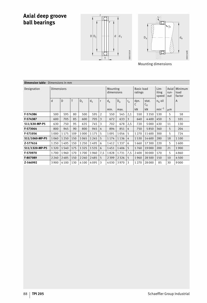
88 TPI 205 Schaeffler Group Industrial
Axial deep groove ball bearings
Mounting dimensions
D
r
T
D1 dd 1
r
0001
501A
daDa
ra
ra
0001
569E
Dimension table · Dimensions in mm
Designation Dimensions Mountingdimensions
Basic loadratings
Lim-itingspeed
Axialrun-out
Minimumloadfactor
d D T D1 d1 r da Da ra dyn.C
stat.C0
nG oil A
min. max. kN kN min–1 �m
F-574386 500 595 80 500 595 2 550 545 2,1 550 3 350 530 5 58
F-574387 600 705 85 600 705 3 672 633 3 640 4 400 450 5 101
511/630-MP-P5 630 750 95 635 745 3 702 678 2,5 720 5 000 430 11 130
F-573064 800 945 90 800 945 4 894 851 4 750 5 850 360 5 204
F-571056 1 000 1 175 109 1 000 1 175 5 1 091 1 056 5 1 270 11 600 300 5 724
511/1060-MP-P5 1 060 1 250 150 1 065 1 245 5 1 174 1 136 4 1 530 14 600 280 18 1 100
Z-577616 1 250 1 495 150 1 250 1 495 6 1 412 1 337 6 1 660 17 300 220 5 1 600
511/1320-MP-P5 1 320 1 540 175 1 325 1 535 6 1 451 1 406 5 1 760 19 000 200 21 1 900
F-570970 1 700 1 960 170 1 700 1 960 7,5 1 828 1 731 7,5 2 400 30 000 170 5 4 860
F-807089 2 240 2 485 150 2 240 2 485 5 2 399 2 326 5 1 960 28 500 150 10 4 500
Z-546992 3 900 4 100 130 4 100 4 095 3 4 030 3 970 3 1 270 28 000 85 30 9 000

Schaeffler Group Industrial TPI 205 89
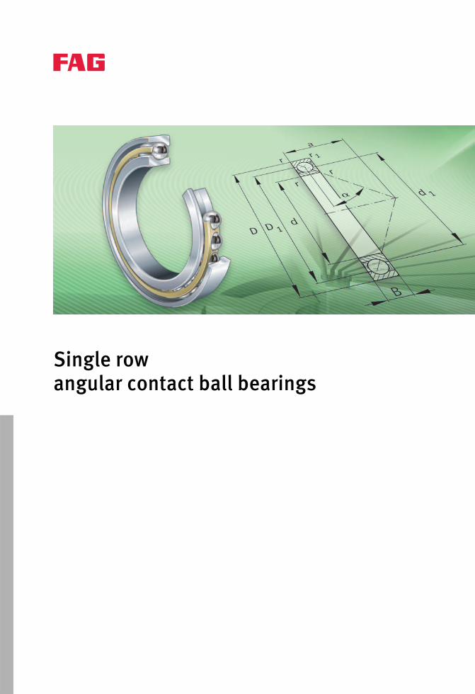
Single rowangular contact ball bearings
Schaeffler Group Industrial TPI 205 91
Page
Single row angular contact ball bearings
Product overview Single row angular contact ball bearings .................................... 92
Features Radial and axial load capacity.................................................... 93
Sealing...................................................................................... 93
Lubrication................................................................................ 93
Operating temperature .............................................................. 93
Cages........................................................................................ 93
Suffixes..................................................................................... 93
Design andsafety guidelines
Equivalent dynamic bearing load ............................................... 94
Minimum load ........................................................................... 94
Speeds...................................................................................... 94
Design of bearing arrangements ................................................ 95
Accuracy Dimensional and geometrical tolerances.................................... 95
Dimension tables Angular contact ball bearings, single row ................................... 96
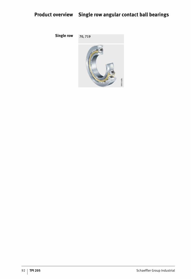
92 TPI 205 Schaeffler Group Industrial
Product overview Single row angular contact ball bearings
Single row 70, 719
0001
4d8c
Schaeffler Group Industrial TPI 205 93
Single row angular contact ball bearings
Features Single row angular contact ball bearings are, with a few exceptions, self-retaining units with solid inner and outer rings and ball andcage assemblies with cages. The raceways of the inner and outer rings are offset from each other along the bearing axis. The angular adjustment facility of these bearings is very limited.
Radial and axial load capacity Single row angular contact ball bearings can support axial forces in one direction and high radial forces. They must be axially adjusted against a second bearing.The axial load carrying capacity is dependent on the contact angle. Bearings with a contact angle 40° have a higher axial load carrying capacity than those with a contact angle 30°.
Sealing The bearings are not sealed.
Lubrication Single row angular contact ball bearings can be lubricated with grease or oil.
Operating temperature Angular contact ball bearings without seals can be used at operating temperatures from –30 °C to +150 °C.Bearings with a diameter D 240 mm are dimensionally stableup to +200 °C.
Cages Angular contact ball bearings with ball-guided solid window cages made from brass have, in the case of bearings of standardised series, the suffix MP.The suffixes MPA or MPB(S) indicate bearings with a solid window cage made from brass that is guided on the outer ring or inner ring.
Suffixes Suffixes for available designs of standard bearings: see table.
Available designs Suffix Description Design
B Modified internal construction Standard
MP Solid brass cage Standard
P5 Bearings in tolerance class P5 Special design
M15 With measurement record Special design,available by agreementJ15 Actual value indication, marking
94 TPI 205 Schaeffler Group Industrial
Single row angular contact ball bearings
Design andsafety guidelines
Equivalent dynamicbearing load
The equivalent dynamic load P is valid for bearings that are subjected to radial and axial dynamic loads. It gives the same rating life as the combined bearing load occurring in practice.For bearings under dynamic loading, the following applies:
Contact angle 40°
Fa kNAxial dynamic bearing loadFr kNRadial dynamic bearing loadP kNEquivalent dynamic bearing load for combined load.
For bearings under dynamic loading, the following applies:Contact angle 30°
Fa kNAxial dynamic bearing loadFr kNRadial dynamic bearing loadP kNEquivalent dynamic bearing load for combined load.
Minimum load In continuous operation, angular contact ball bearings withcage must therefore be subjected to a minimum load of the orderof P/Cr 0,01.
Speeds For the limiting speeds nG of the bearings, see dimension table.The kinematic limiting speeds nG for the main bearing should notbe exceeded.
Bearing arrangement Load ratio Equivalent dynamicbearing load
Single bearingP = Fr
P = 0,35 · Fr + 0,57 · Fa
FFa
r� 1 14,
FFa
r 1 14,
Bearing arrangement Load ratio Equivalent dynamicbearing load
Single bearingP = Fr
P = 0,39 · Fr + 0,76 · Fa
FF
a
r� 0 8,
FFa
r> 0 8,
Schaeffler Group Industrial TPI 205 95
Designof bearing arrangements
In order to make comprehensive use of the performance capacityof the bearings, the adjacent construction must be of an appropriate design.
Shaft and housing tolerances Recommended shaft tolerances for radial bearings with cylindrical bore, see table, page 37.Recommended housing tolerances for radial bearings,see table, page 38.
Mounting dimensions The bearing table gives the maximum dimension of the radii ra and ra1 and the diameters of the abutment shoulders Da, Db and da.
AccuracyDimensional and
geometrical tolerancesAngular contact ball bearings with standardised main dimensions correspond to DIN 628-1.The dimensional and geometrical tolerances of the standardised bearings correspond to tolerance class P5 to DIN 620-2.We can provide the tolerances of the non-standardised bearingsby agreement.
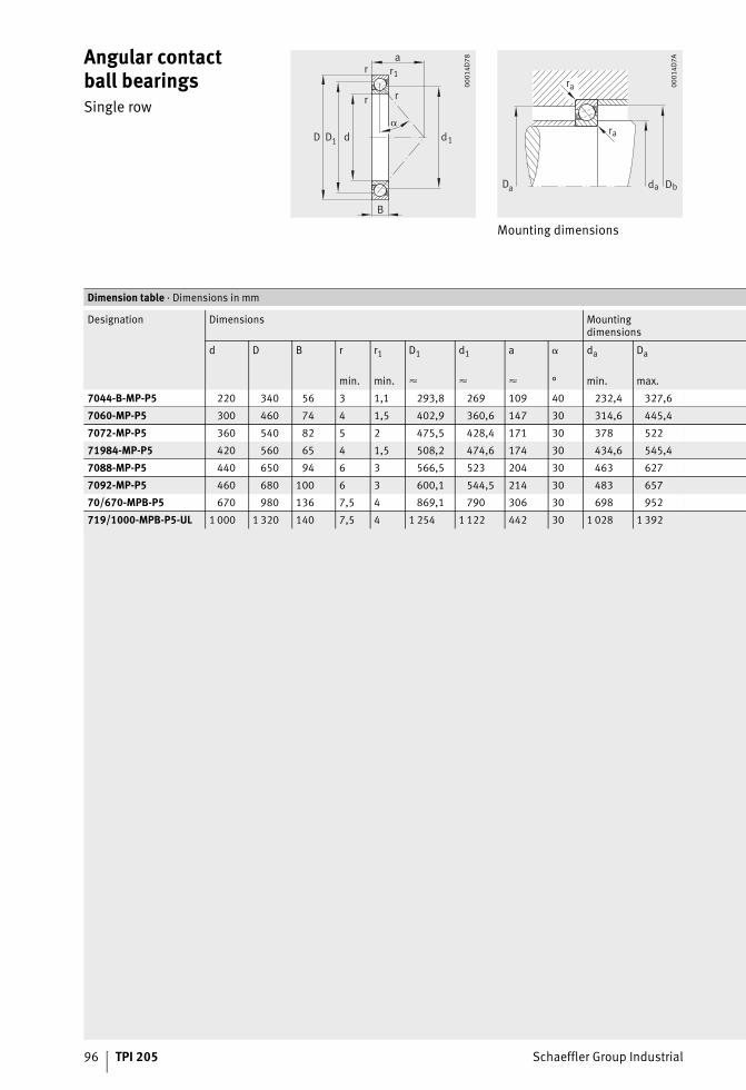
96 TPI 205 Schaeffler Group Industrial
Angular contactball bearingsSingle row
Mounting dimensions
d
ar
B
D
r r
d1D1
r1
0001
4D78
d D
ra
ra
D a ba
0001
4D7A
Dimension table · Dimensions in mm
Designation Dimensions Mountingdimensions
d D B r r1 D1 d1 a da Da
min. min. � � � ° min. max.
7044-B-MP-P5 220 340 56 3 1,1 293,8 269 109 40 232,4 327,6
7060-MP-P5 300 460 74 4 1,5 402,9 360,6 147 30 314,6 445,4
7072-MP-P5 360 540 82 5 2 475,5 428,4 171 30 378 522
71984-MP-P5 420 560 65 4 1,5 508,2 474,6 174 30 434,6 545,4
7088-MP-P5 440 650 94 6 3 566,5 523 204 30 463 627
7092-MP-P5 460 680 100 6 3 600,1 544,5 214 30 483 657
70/670-MPB-P5 670 980 136 7,5 4 869,1 790 306 30 698 952
719/1000-MPB-P5-UL 1 000 1 320 140 7,5 4 1 254 1 122 442 30 1 028 1 392
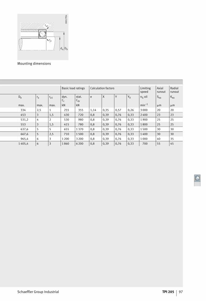
Schaeffler Group Industrial TPI 205 97
Mounting dimensions
da Db
ra
ra1
0001
7FE4
Basic load ratings Calculation factors Limitingspeed
Axialrunout
Radialrunout
Db ra ra1 dyn.Cr
stat.C0r
e X Y Y0 nG oil Sea Kea
max. max. max. kN kN min–1 �m �m
334 2,5 1 255 355 1,14 0,35 0,57 0,26 3 000 20 20
453 3 1,5 430 720 0,8 0,39 0,76 0,33 2 400 23 23
531,2 4 2 530 980 0,8 0,39 0,76 0,33 1 900 25 25
553 3 1,5 415 780 0,8 0,39 0,76 0,33 1 800 25 25
637,6 5 5 655 1 370 0,8 0,39 0,76 0,33 1 500 30 30
667,6 5 2,5 710 1 500 0,8 0,39 0,76 0,33 1 400 30 30
965,4 6 3 1 200 3 200 0,8 0,39 0,76 0,33 1 000 40 35
1 405,4 6 3 1 860 6 200 0,8 0,39 0,76 0,33 700 55 45
Axial cylindrical roller bearings
Schaeffler Group Industrial TPI 205 99
Page
Axial cylindrical roller bearings
Product overview Axial cylindrical roller bearings ............................................... 100
Features Single direction bearings ........................................................ 101
Operating temperature ........................................................... 101
Cages..................................................................................... 101
Suffixes.................................................................................. 101
Design andsafety guidelines
Equivalent dynamic bearing load ............................................ 102
Equivalent static bearing load................................................. 102
Minimum axial load ................................................................ 102
Limiting speed........................................................................ 103
Design of adjacent parts ......................................................... 103
Accuracy Dimensional and geometrical tolerances................................. 103
Dimension tables Axial cylindrical roller bearings ............................................... 104
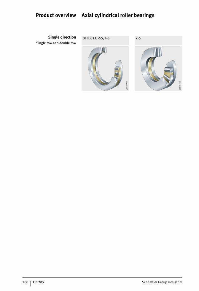
100 TPI 205 Schaeffler Group Industrial
Product overview Axial cylindrical roller bearings
Single directionSingle row and double row
810, 811, Z-5, F-8 Z-5
0001
500e
0001
57AD
Schaeffler Group Industrial TPI 205 101
Axial cylindrical roller bearings
Features Axial cylindrical roller bearings have a low axial section height,high load capacity and high rigidity.
Single direction bearings Single direction axial cylindrical roller bearings comprise an axial cylindrical roller and cage assembly, an externally centred housing locating washer and an internally centred shaft locating washer.The bore diameter, outside diameter and running surface of the housing locating washer and the shaft locating washer are precision machined.The bearings can support axial forces in one direction.Bearings 810 and 811 are single row bearings and conformto DIN 722/ISO 104.Angular contact ball bearings Z-5 and F-8 are special bearings and have non-standardised dimensions and designations.
Operating temperature Axial cylindrical roller bearings and axial cylindrical roller andcage assemblies can be used at operating temperatures from –30 °C to +150 °C.
Cages The bearings generally have brass cages. These are indicatedin bearings of series 810 and 811 by the suffix M. We can provide information on the cage design in special bearings by agreement.
Suffixes Suffixes for available designs of standardised bearings: see table.
Available designs
1) The design of the bearings with non-standardised designations (Z-5, F-8)is available by agreement from us.
Suffix1) Description Design
M Brass cage Standard
MB Solid brass cage, internally guided
P5 Improved dimensional and geometrical accuracy Special design
P4 High dimensional and geometrical accuracy
102 TPI 205 Schaeffler Group Industrial
Axial cylindrical roller bearings
Design andsafety guidelines
Axial cylindrical roller bearings can support axial forces only.
Equivalent dynamicbearing load
For bearings under dynamic loading, the following applies:
P kNEquivalent dynamic bearing loadFa kNAxial dynamic bearing load.
Equivalent staticbearing load
For bearings under static loading, the following applies:
P0 kNEquivalent static bearing loadF0a kNAxial static bearing load.
Minimum axial load In order to ensure reliable operation, the minimum axial load Fa min in accordance with the formula must be applied:
Fa min NMinimum axial loadC0a N (observe the dimension)Basic static load ratingka –Factor for determining the minimum load, see tablen min–1
Speed.
Factor ka
1) We can provide ka values for non-standardised bearings by agreement.
P Fa=
P F a0 0=
F C kC n
a a aa
min ,= ⋅ +⋅⎛
⎝⎜⎞⎠⎟
0 000510
00
8
2
Series Factorka
1)
810 1,3
811 1,4
Schaeffler Group Industrial TPI 205 103
Limiting speedThe limiting speeds given in the dimension tables are valid foroil lubrication.
Design of adjacent parts Axial bearing washers must be fully supported over their entire surface.The abutment shoulders should be rigid, flat and perpendicularto the axis of rotation.
Tolerances for shafts andhousing bores
Tolerances for shafts and housing bores: see table.
Shaft and housing bore tolerances
Orientation of washersThe axial bearing washers must be fitted with the raceway side facing the rolling elements.On housing locating washers, the raceway side is indicatedby the smaller chamfer on the outside diameter.On shaft locating washers, the raceway side is indicatedby the smaller chamfer on the bore diameter.
AccuracyDimensional and
geometrical tolerancesThe dimensional and geometrical tolerances of axial bearing washers GS and WS are in accordance with tolerance class P5 or better to DIN 620, see dimension table.
Bearing component Shaft tolerance Bore tolerance
Cage Internally guided h8 –
Housing locating washer – – H7 (K7)
Shaft locating washer – h6 (j6) –
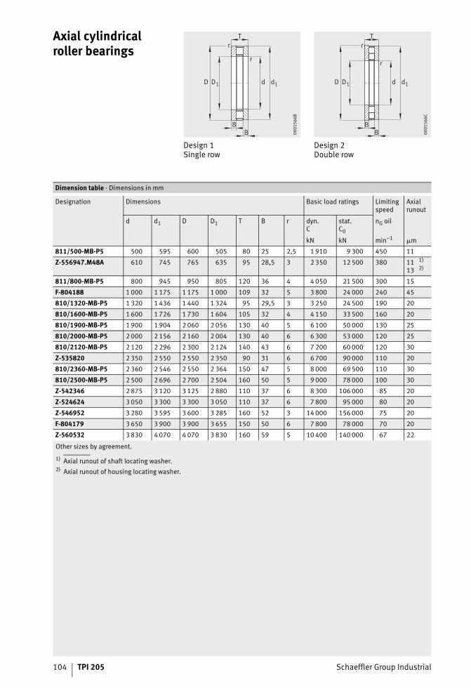
104 TPI 205 Schaeffler Group Industrial
Axial cylindrical roller bearings
Design 1Single row
Design 2Double row
BB
DD
r
r
1 1d d
T
0001
566B
BB
DD
r
r
1 1d d
T
0001
566C
Other sizes by agreement.
1) Axial runout of shaft locating washer.2) Axial runout of housing locating washer.
Dimension table · Dimensions in mm
Designation Dimensions Basic load ratings Limitingspeed
Axialrunout
d d1 D D1 T B r dyn.C
stat.C0
nG oil
kN kN min–1 �m
811/500-MB-P5 500 595 600 505 80 25 2,5 1 910 9 300 450 11
Z-556947.M48A 610 745 765 635 95 28,5 3 2 350 12 500 380 1113
1)2)
811/800-MB-P5 800 945 950 805 120 36 4 4 050 21 500 300 15
F-804188 1 000 1 175 1 175 1 000 109 32 5 3 800 24 000 240 45
810/1320-MB-P5 1 320 1 436 1 440 1 324 95 29,5 3 3 250 24 500 190 20
810/1600-MB-P5 1 600 1 726 1 730 1 604 105 32 4 4 150 33 500 160 20
810/1900-MB-P5 1 900 1 904 2 060 2 056 130 40 5 6 100 50 000 130 25
810/2000-MB-P5 2 000 2 156 2 160 2 004 130 40 6 6 300 53 000 120 25
810/2120-MB-P5 2 120 2 296 2 300 2 124 140 43 6 7 200 60 000 120 30
Z-535820 2 350 2 550 2 550 2 350 90 31 6 6 700 90 000 110 20
810/2360-MB-P5 2 360 2 546 2 550 2 364 150 47 5 8 000 69 500 110 30
810/2500-MB-P5 2 500 2 696 2 700 2 504 160 50 5 9 000 78 000 100 30
Z-542346 2 875 3 120 3 125 2 880 110 37 6 8 300 106 000 85 20
Z-524624 3 050 3 300 3 300 3 050 110 37 6 7 800 95 000 80 20
Z-546952 3 280 3 595 3 600 3 285 160 52 3 14 000 156 000 75 20
F-804179 3 650 3 900 3 900 3 655 150 50 6 7 800 78 000 70 20
Z-560532 3 830 4 070 4 070 3 830 160 59 5 10 400 140 000 67 22

Schaeffler Group Industrial TPI 205 105
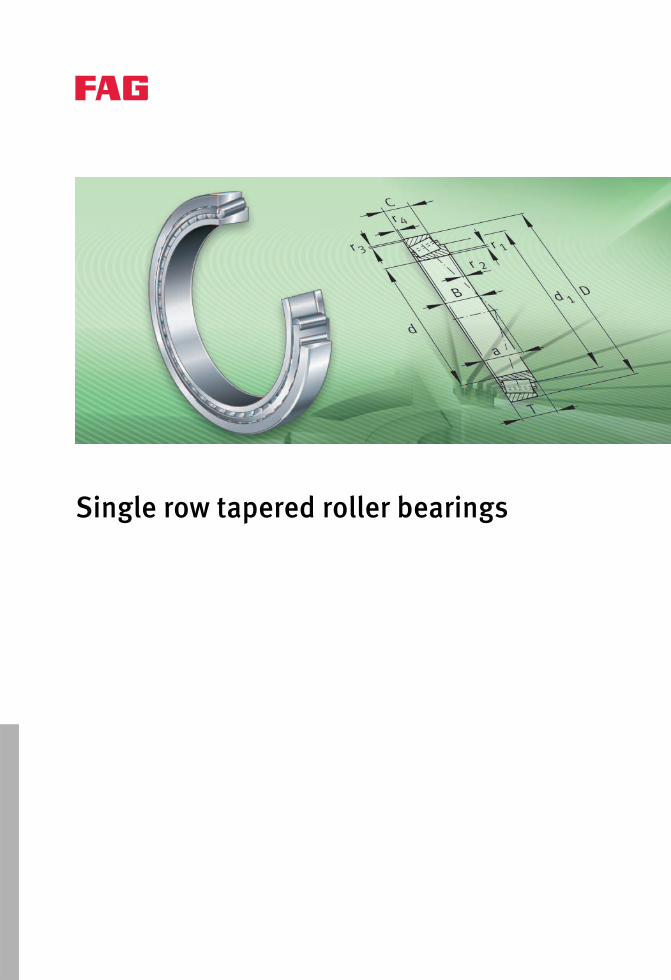
Single row tapered roller bearings
Schaeffler Group Industrial TPI 205 107
Page
Single row tapered roller bearings
Product overview Single row tapered roller bearings........................................... 108
Features Radial and axial load capacity................................................. 109
Compensation of angular misalignments ................................ 109
Sealing................................................................................... 109
Lubrication............................................................................. 109
Operating temperature ........................................................... 109
Cages..................................................................................... 110
Suffixes.................................................................................. 110
Design andsafety guidelines
Equivalent dynamic bearing load ............................................ 110
Equivalent static bearing load................................................. 111
Minimum load ........................................................................ 111
Speeds................................................................................... 111
Design of bearing arrangements ............................................. 111
Accuracy Bearings in metric sizes .......................................................... 112
Bearings in inch sizes ............................................................. 114
Dimension tables Tapered roller bearings, single row ......................................... 118
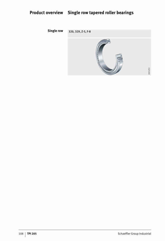
108 TPI 205 Schaeffler Group Industrial
Product overview Single row tapered roller bearings
Single row 320, 329, Z-5, F-8
0001
4FE2
Schaeffler Group Industrial TPI 205 109
Single row tapered roller bearings
Features Single row tapered roller bearings comprise solid inner andouter rings with tapered raceways and tapered rollers with cages made from pressed sheet steel.The bearings are not self-retaining. As a result, the inner ring withthe rollers and the cage can be fitted separately from the outer ring.In addition to bearings with standardised main dimensions and standardised designations, special bearings in metric andinch sizes are also available, which have the non-standardised designations Z-5 or F-8.For new designs, bearings in metric sizes should always be usedin preference.
Radial and axial load capacity Single row tapered roller bearings can support axial forces inone direction and high radial forces. They must be axially adjusted against a second bearing.
Contact angle The axial load carrying capacity is dependent on the contact angle; this means that the larger the angle, the higher the axial load to which the bearing can be subjected.The size of the contact angle and thus the load carrying capacityis indicated by the bearing-specific value e in the dimension tables.
Compensation of angularmisalignments
The modified line contact between the tapered rollers andthe raceways ensures optimum stress distribution at the contact points, prevents edge stresses and allows the bearings to undergo angular adjustment.At a load ratio P/Cr � 0,2, the tilting of the bearing rings relativeto each other must not exceed 4 angular minutes. For higher loads or tilting angles, please contact us.
Sealing Standard bearings are not sealed.
Lubrication They can be lubricated using oil or grease.
Operating temperature Single row tapered roller bearings can be used at operating temperatures from –30 °C to +120 °C. For continuous operating temperatures +120 °C, please contact us.Bearings with outside diameters of more than 240 mm are dimensionally stable up to +200 °C.
110 TPI 205 Schaeffler Group Industrial
Single row tapered roller bearings
Cages Single row tapered roller bearings have pressed cages made from sheet steel.Since these project laterally to a certain extent, the mounting dimensions in the dimension tables and the cage projection, page 111 must be observed.
Suffixes Suffixes for available designs: see table.
Available designs
Design andsafety guidelines
Equivalent dynamicbearing load
The equivalent dynamic load P is valid for bearings that are subjected to radial and axial dynamic loads. It gives the same rating life as the combined bearing load occurring in practice.For bearings under dynamic loading, the following applies:
Single bearings under dynamic load
Fa kNAxial dynamic bearing loadFr kNRadial dynamic bearing loade, Y –Factors, see dimension tableP kNEquivalent dynamic bearing load for combined load.
Suffix Description Design
A Modified internal construction Standard
X External dimensions matchedto international standards
P5 Increased accuracy Special designs
Load ratio Equivalent dynamic bearing load
P = Fr
P = 0,4 · Fr + Y · Fa
FF
ea
r�
F
Fea
r
Schaeffler Group Industrial TPI 205 111
Equivalent staticbearing load
The equivalent static load P0 is valid for bearings that are subjected to radial and axial static loads. It induces the same load at the centre point of the most heavily loaded contact point between the rolling element and raceway as the combined bearing load occurring in practice.For single bearings under static load, the following applies:
Single bearings under static load
F0a kNAxial static bearing loadF0r kNRadial static bearing loadY0 –Factor, see dimension tableP0 kNEquivalent static bearing load for combined load.
Minimum load In order to ensure operation without slippage, the bearings must be subjected to a minimum load Fr min in a radial direction. This applies particularly in the case of high speeds and high accelerations.For continuous operation, roller bearings with cage must therefore be subjected to a minimum load of the order of P/Cr � 0,02.
SpeedsThe component limiting the speed is the main bearing.The kinematic limiting speeds nG for the main bearings should not be exceeded, see dimension tables.
Design of bearingarrangements
In order to make comprehensive use of the performance capacityof the bearings, the adjacent construction must be of an appropriate design.
Shaft and housing tolerances Recommended shaft tolerances for radial bearings with cylindrical bore, see table, page 37.Recommended housing tolerances for radial bearings,see table, page 38.
Mounting dimensions The dimension tables give the maximum dimensions of the radii ra and rb and the diameters of the abutment shoulders.
Cage projectionThe cages project laterally to a certain extent. In order to prevent grazing, the lateral minimum distances Ca and Cb in the dimension tables must be taken into consideration in the design of the adjacent construction.
Load ratio Equivalent static load
P0 = F0r
P0 = 0,5 · F0r + Y0 · F0a
FF Y
a
r
0
0 0
12
�⋅
FF Y
a
r
0
0 0
12
⋅
112 TPI 205 Schaeffler Group Industrial
Single row tapered roller bearings
AccuracyBearings in metric sizes The main dimensions of the standardised bearings conform to
DIN ISO 355 and DIN 720, the dimensional and running tolerances conform to DIN 620-2.
Tolerance class P5 Tapered roller bearings with restricted tolerances to tolerance class P5 to DIN 620-2, see tables.
Inner ring tolerances
Inner ring tolerancescontinued
Bore Bore deviation Variation Radial runout
d dmp Vdsp Vdmp Kiamm �m �m �m �m
over incl. max. min. max. max. max.
250 315 0 –25 19 13 13
315 400 0 –30 23 15 15
400 500 0 –35 28 17 20
500 630 0 –40 35 20 25
630 800 0 –50 45 25 30
800 1 000 0 –60 60 30 37
1 000 1 250 0 –75 75 37 45
1 250 1 600 0 –90 90 45 55
Bore Axial runoutof end face
Width deviation
d Sd Bsmm �m �m
over incl. max. max. min.
250 315 13 0 –700
315 400 15 0 –800
400 500 17 0 –900
500 630 20 0 –1 100
630 800 25 0 –1 600
800 1 000 30 0 –2 000
1 000 1 250 40 0 –2 000
1 250 1 600 50 0 –2 000
Schaeffler Group Industrial TPI 205 113
Outer ring tolerances
Outer ring tolerancescontinued
Outside diameter Deviationof outside diameter
Variation Radial runout
D Dmp VDsp VDmp Keamm �m �m �m �m
over incl. max. min. max. max. max.
250 315 0 –25 19 13 18
315 400 0 –28 22 14 20
400 500 0 –33 26 17 23
500 630 0 –38 30 20 25
630 800 0 –45 38 25 30
800 1 000 0 –60 50 30 35
1 000 1 250 0 –80 65 38 52
1 250 1 600 0 –100 90 50 62
1 600 2 000 0 –125 120 65 73
Bore Runoutof outside surface generatrix
Width deviation
d SD Csmm �m �m
over incl. max. max. min.
250 315 13 0 –600
315 400 13 0 –700
400 500 17 0 –800
500 630 20 0 –900
630 800 25 0 –1 100
800 1 000 30 0 –1 600
1 000 1 250 38 0 –2 000
1 250 1 600 50 0 –2 000
1 600 2 000 65 0 –2 000
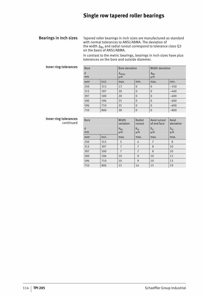
114 TPI 205 Schaeffler Group Industrial
Single row tapered roller bearings
Bearings in inch sizes Tapered roller bearings in inch sizes are manufactured as standard with normal tolerances to ANSI/ABMA. The deviation ofthe width Bs and radial runout correspond to tolerance class Q3on the basis of ANSI/ABMA.In contrast to the metric bearings, bearings in inch sizes have plus tolerances on the bore and outside diameter.
Inner ring tolerances
Inner ring tolerancescontinued
Bore Bore deviation Width deviation
d dmp Bsmm �m �m
over incl. max. min. max. min.
250 315 13 0 0 –350
315 397 20 0 0 –400
397 500 20 0 0 –400
500 596 25 0 0 –600
596 710 25 0 0 –600
710 800 38 0 0 –800
Bore Width variation
Radial runout
Axial runoutof end face
Axial deviation
d VBs Kia Sd Siamm �m �m �m �m
over incl. max. max. max. max.
250 315 5 4 7 8
315 397 7 7 8 10
397 500 7 7 8 10
500 596 10 9 10 13
596 710 10 9 10 13
710 800 15 14 15 19
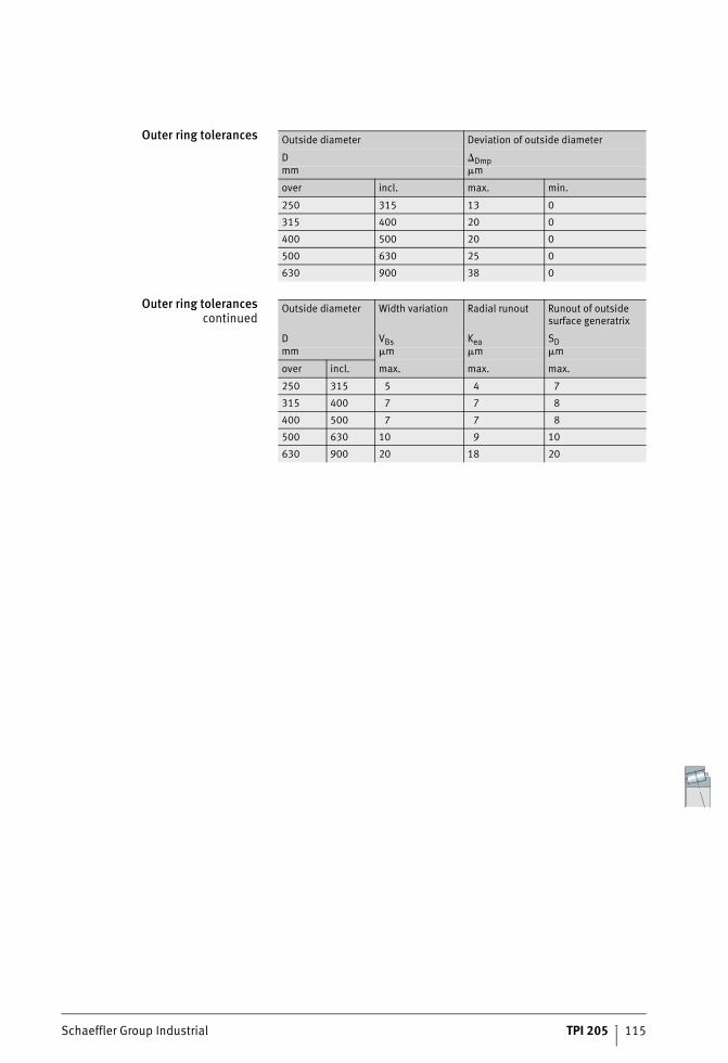
Schaeffler Group Industrial TPI 205 115
Outer ring tolerances
Outer ring tolerancescontinued
Outside diameter Deviation of outside diameter
D Dmpmm �m
over incl. max. min.
250 315 13 0
315 400 20 0
400 500 20 0
500 630 25 0
630 900 38 0
Outside diameter Width variation Radial runout Runout of outsidesurface generatrix
D VBs Kea SDmm �m �m �m
over incl. max. max. max.
250 315 5 4 7
315 400 7 7 8
400 500 7 7 8
500 630 10 9 10
630 900 20 18 20
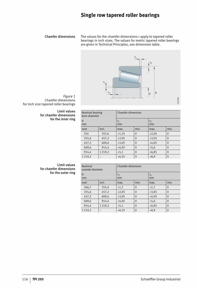
116 TPI 205 Schaeffler Group Industrial
Single row tapered roller bearings
Chamfer dimensions The values for the chamfer dimensions r apply to tapered roller bearings in inch sizes. The values for metric tapered roller bearings are given in Technical Principles, see dimension table.
Limit valuesfor chamfer dimensions
for the inner ring
Limit valuesfor chamfer dimensions
for the outer ring
Figure 1Chamfer dimensions
for inch size tapered roller bearings
d D
r4
r3
r1
r2
156
846
Nominal bearingbore diameter
Chamfer dimension
d r1 r2mm mm mm
over incl. max. min. max. min.
254 355,6 +1,25 0 +2,05 0
355,6 457,2 +2,05 0 +3,05 0
457,2 609,6 +3,05 0 +4,05 0
609,6 914,4 +4,05 0 +5,6 0
914,4 1 219,2 +5,1 0 +6,85 0
1 219,2 – +6,35 0 +8,9 0
Nominaloutside diameter
Chamfer dimension
D r3 r4mm mm mm
over incl. max. min. max. min.
266,7 355,6 +1,7 0 +1,7 0
355,6 457,2 +2,05 0 +3,05 0
457,2 609,6 +3,05 0 +4,05 0
609,6 914,4 +4,05 0 +5,6 0
914,4 1 219,2 +5,1 0 +6,85 0
1 219,2 – +6,35 0 +8,9 0

Schaeffler Group Industrial TPI 205 117
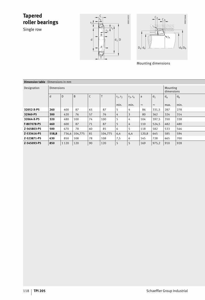
118 TPI 205 Schaeffler Group Industrial
Taperedroller bearingsSingle row
Mounting dimensions
B
a
r1
1
r2
r4r3
C
T
d Dd
0001
5022 C
r
r
DD
C
d d
a
b
a
ba
b
a b
0001
5646
Dimension table · Dimensions in mm
Designation Dimensions Mountingdimensions
d D B C T r1, r2 r3, r4 a d1 da db
min. min. � � max. min.
32052-X-P5 260 400 87 65 87 5 4 86 331,5 287 278
32960-P5 300 420 76 57 76 4 3 80 362 324 314
32064-X-P5 320 480 100 74 100 5 4 104 397,5 350 338
F-807078-P5 460 600 87 71 87 5 4 110 524,5 482 480
Z-565803-P5 500 670 78 60 85 6 5 118 582 533 546
Z-533416-P5 558,8 736,6 104,775 81 104,775 6,4 6,4 120,8 645 585 594
Z-523871-P5 630 850 108 78 108 7,5 6 145 728 665 700
Z-545093-P5 850 1 120 120 90 120 5 5 169 975,2 910 928
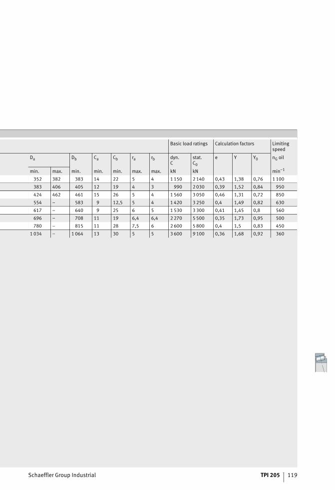
Schaeffler Group Industrial TPI 205 119
Basic load ratings Calculation factors Limitingspeed
Da Db Ca Cb ra rb dyn.C
stat.C0
e Y Y0 nG oil
min. max. min. min. min. max. max. kN kN min–1
352 382 383 14 22 5 4 1 150 2 140 0,43 1,38 0,76 1 100
383 406 405 12 19 4 3 990 2 030 0,39 1,52 0,84 950
424 462 461 15 26 5 4 1 560 3 050 0,46 1,31 0,72 850
554 – 583 9 12,5 5 4 1 420 3 250 0,4 1,49 0,82 630
617 – 640 9 25 6 5 1 530 3 300 0,41 1,45 0,8 560
696 – 708 11 19 6,4 6,4 2 270 5 500 0,35 1,73 0,95 500
780 – 815 11 28 7,5 6 2 600 5 800 0,4 1,5 0,83 450
1 034 – 1 064 13 30 5 5 3 600 9 100 0,36 1,68 0,92 360
Radial cylindrical roller bearings
Schaeffler Group Industrial TPI 205 121
Page
Radial cylindrical roller bearings
Product overview Radial cylindrical roller bearings ............................................. 122
Features Ideal non-locating bearings .................................................... 123
Bearings with smaller cross-section ........................................ 123
Double row cylindrical roller bearings ..................................... 123
Sealing................................................................................... 124
Lubrication............................................................................. 124
Operating temperature ........................................................... 124
Cages..................................................................................... 124
Suffixes.................................................................................. 124
Marking of bearings................................................................ 124
Design andsafety guidelines
Load carrying capacity and operating life ................................ 125
Equivalent static bearing load................................................. 125
Static load safety factor .......................................................... 125
Clearance adjustment of cylindrical roller bearings.................. 125
Speeds................................................................................... 126
Radial rigidity ......................................................................... 126
Design of bearing arrangements ............................................. 127
Accuracy Tolerances of class SP for double row bearings ....................... 134
Tolerances of class UP for double row bearings ....................... 136
Radial internal clearance ........................................................ 138
Dimension tables Super precision cylindrical roller bearings,double row ............................................................................. 140
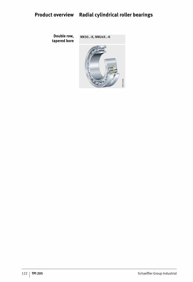
122 TPI 205 Schaeffler Group Industrial
Product overview Radial cylindrical roller bearings
Double row,tapered bore
NN30..-K, NNU49..-K
0001
4e0b
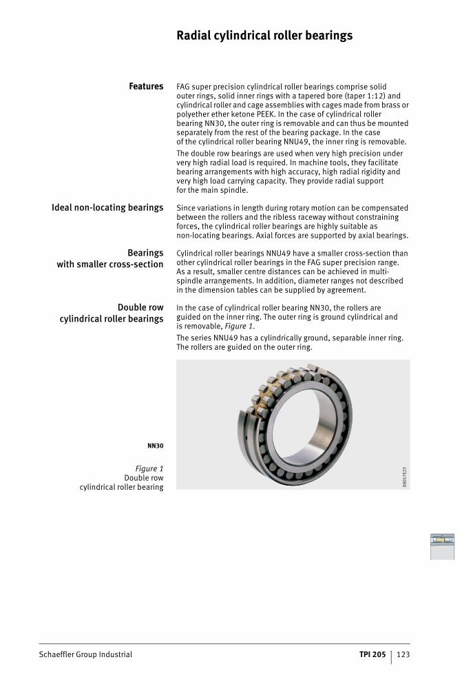
Schaeffler Group Industrial TPI 205 123
Radial cylindrical roller bearings
Features FAG super precision cylindrical roller bearings comprise solidouter rings, solid inner rings with a tapered bore (taper 1:12) and cylindrical roller and cage assemblies with cages made from brass or polyether ether ketone PEEK. In the case of cylindrical roller bearing NN30, the outer ring is removable and can thus be mounted separately from the rest of the bearing package. In the caseof the cylindrical roller bearing NNU49, the inner ring is removable.The double row bearings are used when very high precision under very high radial load is required. In machine tools, they facilitate bearing arrangements with high accuracy, high radial rigidity and very high load carrying capacity. They provide radial supportfor the main spindle.
Ideal non-locating bearings Since variations in length during rotary motion can be compensated between the rollers and the ribless raceway without constraining forces, the cylindrical roller bearings are highly suitable as non-locating bearings. Axial forces are supported by axial bearings.
Bearingswith smaller cross-section
Cylindrical roller bearings NNU49 have a smaller cross-section than other cylindrical roller bearings in the FAG super precision range.As a result, smaller centre distances can be achieved in multi-spindle arrangements. In addition, diameter ranges not describedin the dimension tables can be supplied by agreement.
Double rowcylindrical roller bearings
In the case of cylindrical roller bearing NN30, the rollers areguided on the inner ring. The outer ring is ground cylindrical andis removable, Figure 1.The series NNU49 has a cylindrically ground, separable inner ring. The rollers are guided on the outer ring.
NN30
Figure 1Double row
cylindrical roller bearing 0001
7E23
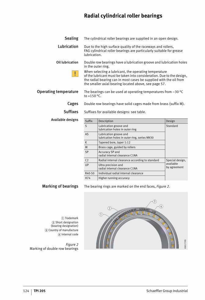
124 TPI 205 Schaeffler Group Industrial
Radial cylindrical roller bearings
Sealing The cylindrical roller bearings are supplied in an open design.
Lubrication Due to the high surface quality of the raceways and rollers, FAG cylindrical roller bearings are particularly suitable for grease lubrication.
Oil lubrication Double row bearings have a lubrication groove and lubrication holes in the outer ring.When selecting a lubricant, the operating temperatureof the lubricant must be taken into consideration. Due to the design, the radial bearing can in most cases be supplied with the oil fromthe smaller axial bearing located above, see page 57.
Operating temperature The bearings can be used at operating temperatures from –30 °Cto +150 °C.
Cages Double row bearings have solid cages made from brass (suffix M).
Suffixes Suffixes for available designs: see table.
Available designs
Marking of bearings The bearing rings are marked on the end faces, Figure 2.
Suffix Description Design
S Lubrication groove andlubrication holes in outer ring
Standard
AS Lubrication groove andlubrication holes in outer ring, series NN30
K Tapered bore, taper 1:12
M Brass cage, guided by rollers
SP Accuracy SP andradial internal clearance C1NA
C2 Radial internal clearance according to standard Special design, availableby agreement
UP Ultra precision andradial internal clearance C1NA
R40-50 Individual radial internal clearance
H74 Higher running accuracy
� Trademark� Short designation
(bearing designation)� Country of manufacture
� Internal code
Figure 2Marking of double row bearings
F A G NNU4920-S-K-M-SP GERMANY 15B
4
3
1
2
0001
779D
Schaeffler Group Industrial TPI 205 125
Design andsafety guidelines
Load carrying capacity andoperating life
Bearing arrangements with super precision cylindrical roller bearings are generally designed in accordance with the require-ments for load carrying capacity, rigidity and accuracy.In practice, failure due to fatigue is not significant for these bearings. Calculation of the rating life L10 in accordance with DIN ISO 281in order to determine the operating life is therefore not appropriate.
Equivalent staticbearing load
The equivalent static bearing load P0 is determined from the radial loads acting on the bearing.Super precision cylindrical roller bearings can support radial forces only.For bearings under static loading, the following applies:
P0 NEquivalent static bearing loadF0r NRadial static bearing load.
Static load safety factor Whether the static load carrying capacity of a bearing is sufficientfor a given static load can be checked with the aid of the static load safety factor S0.
S0 –Static load safety factorC0 NBasic static load ratingP0 NEquivalent static bearing load.
In order to utilise the high accuracy of the bearings, a static load safety factor S0 3 is necessary (S0 8 = fatigue-resistant).
Clearance adjustmentof cylindrical roller bearings
Cylindrical roller bearings with a tapered bore are mountedwith clearance, clearance-free or with preload, see table, page 126.For use in vertical turret lathes, an interference of 5 �m has proved effective.
P F r0 0=
SCP0
0
0=
126 TPI 205 Schaeffler Group Industrial
Radial cylindrical roller bearings
Speeds The limiting speeds nG given in the dimension tables are validfor lubrication with grease or for minimal quantity lubrication with oil and must not be exceeded.In the case of cylindrical roller bearings, the achievable speed is determined by the radial internal clearance in the operational state, see table.
Achievable speeds
dM = (d + D)/2These values are guide values for temperature differences T � 5 K betweenthe inner ring and outer ring. For use in applications with larger temperature differences, please consult the Application Engineering facilities of the Schaeffler Group.
Radial rigidity The radial rigidity cr is the quotient of the radial load and radial displacement.
cr N/�mRadial rigidity, see dimension tablesFr NRadial force�r �mRadial displacement.
Clearance or preload Achievable speed�m min–1
–5 to 0 0,5 · nG grease
2 · 10–5 · dM 0,5 to 0,75 · nG grease
4 · 10–5 · dM 0,75 to 1 · nG grease
1 · 10–4 · dM 1 · nG oil
cF
rr
r=
�
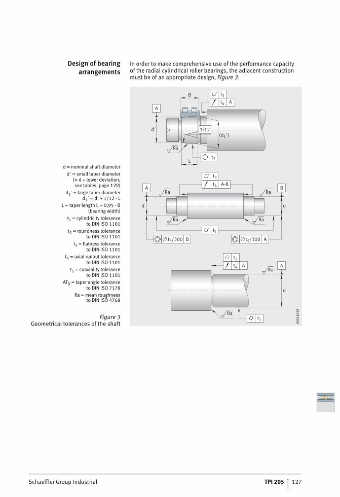
Schaeffler Group Industrial TPI 205 127
Design of bearingarrangements
In order to make comprehensive use of the performance capacityof the radial cylindrical roller bearings, the adjacent construction must be of an appropriate design, Figure 3.
d = nominal shaft diameterd� = small taper diameter
(= d + lower deviation,see tables, page 129)
d1� = large taper diameterd1� = d� + 1/12 · L
L = taper length L = 0,95 · B(bearing width)
t1 = cylindricity toleranceto DIN ISO 1101
t2 = roundness toleranceto DIN ISO 1101
t3 = flatness toleranceto DIN ISO 1101
t4 = axial runout toleranceto DIN ISO 1101
t5 = coaxiality toleranceto DIN ISO 1101
ATD = taper angle toleranceto DIN ISO 7178
Ra = mean roughnessto DIN ISO 4768
Figure 3Geometrical tolerances of the shaft
d�(d1�)
L
B
1:12
At4
t3
A
Ra
t2
A-Bt4
t3
d
t5/300� B
Ra
Ra
A
t5/300 A
Ra
t1
d
�
ARa
At4
t3
d
BRa
Ra t1
0001
6C8A
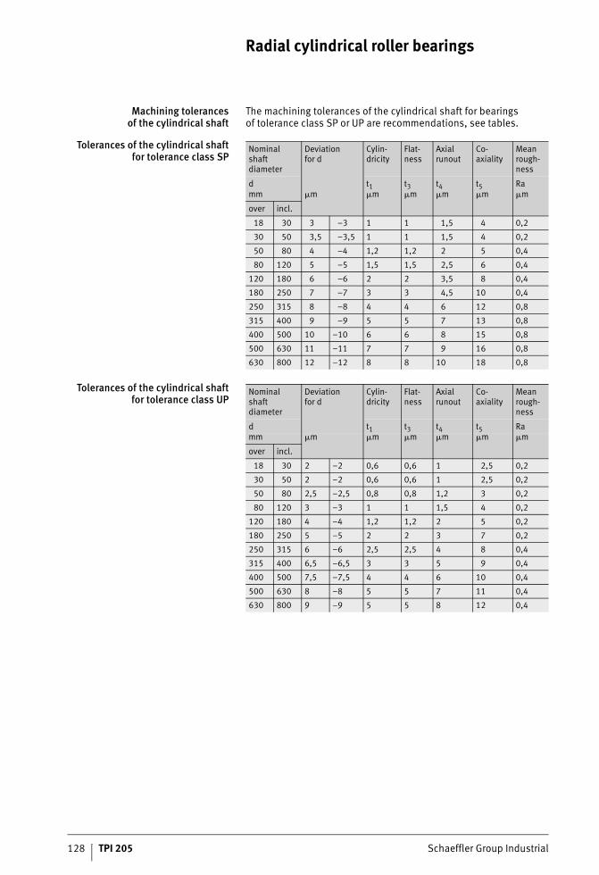
128 TPI 205 Schaeffler Group Industrial
Radial cylindrical roller bearings
Machining tolerancesof the cylindrical shaft
The machining tolerances of the cylindrical shaft for bearingsof tolerance class SP or UP are recommendations, see tables.
Tolerances of the cylindrical shaftfor tolerance class SP
Tolerances of the cylindrical shaftfor tolerance class UP
Nominalshaft diameter
Deviationfor d
Cylin-dricity
Flat-ness
Axial runout
Co-axiality
Mean rough-ness
d t1 t3 t4 t5 Ramm �m �m �m �m �m �m
over incl.
18 30 3 –3 1 1 1,5 4 0,2
30 50 3,5 –3,5 1 1 1,5 4 0,2
50 80 4 –4 1,2 1,2 2 5 0,4
80 120 5 –5 1,5 1,5 2,5 6 0,4
120 180 6 –6 2 2 3,5 8 0,4
180 250 7 –7 3 3 4,5 10 0,4
250 315 8 –8 4 4 6 12 0,8
315 400 9 –9 5 5 7 13 0,8
400 500 10 –10 6 6 8 15 0,8
500 630 11 –11 7 7 9 16 0,8
630 800 12 –12 8 8 10 18 0,8
Nominalshaft diameter
Deviationfor d
Cylin-dricity
Flat-ness
Axial runout
Co-axiality
Mean rough-ness
d t1 t3 t4 t5 Ramm �m �m �m �m �m �m
over incl.
18 30 2 –2 0,6 0,6 1 2,5 0,2
30 50 2 –2 0,6 0,6 1 2,5 0,2
50 80 2,5 –2,5 0,8 0,8 1,2 3 0,2
80 120 3 –3 1 1 1,5 4 0,2
120 180 4 –4 1,2 1,2 2 5 0,2
180 250 5 –5 2 2 3 7 0,2
250 315 6 –6 2,5 2,5 4 8 0,4
315 400 6,5 –6,5 3 3 5 9 0,4
400 500 7,5 –7,5 4 4 6 10 0,4
500 630 8 –8 5 5 7 11 0,4
630 800 9 –9 5 5 8 12 0,4
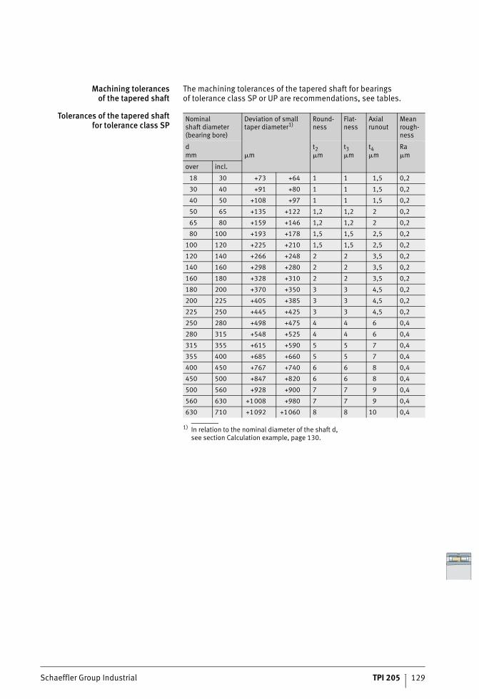
Schaeffler Group Industrial TPI 205 129
Machining tolerancesof the tapered shaft
The machining tolerances of the tapered shaft for bearingsof tolerance class SP or UP are recommendations, see tables.
Tolerances of the tapered shaftfor tolerance class SP
1) In relation to the nominal diameter of the shaft d,see section Calculation example, page 130.
Nominalshaft diameter (bearing bore)
Deviation of small taper diameter1)
Round-ness
Flat-ness
Axial runout
Mean rough-ness
d t2 t3 t4 Ramm �m �m �m �m �m
over incl.
18 30 +73 +64 1 1 1,5 0,2
30 40 +91 +80 1 1 1,5 0,2
40 50 +108 +97 1 1 1,5 0,2
50 65 +135 +122 1,2 1,2 2 0,2
65 80 +159 +146 1,2 1,2 2 0,2
80 100 +193 +178 1,5 1,5 2,5 0,2
100 120 +225 +210 1,5 1,5 2,5 0,2
120 140 +266 +248 2 2 3,5 0,2
140 160 +298 +280 2 2 3,5 0,2
160 180 +328 +310 2 2 3,5 0,2
180 200 +370 +350 3 3 4,5 0,2
200 225 +405 +385 3 3 4,5 0,2
225 250 +445 +425 3 3 4,5 0,2
250 280 +498 +475 4 4 6 0,4
280 315 +548 +525 4 4 6 0,4
315 355 +615 +590 5 5 7 0,4
355 400 +685 +660 5 5 7 0,4
400 450 +767 +740 6 6 8 0,4
450 500 +847 +820 6 6 8 0,4
500 560 +928 +900 7 7 9 0,4
560 630 +1008 +980 7 7 9 0,4
630 710 +1092 +1060 8 8 10 0,4
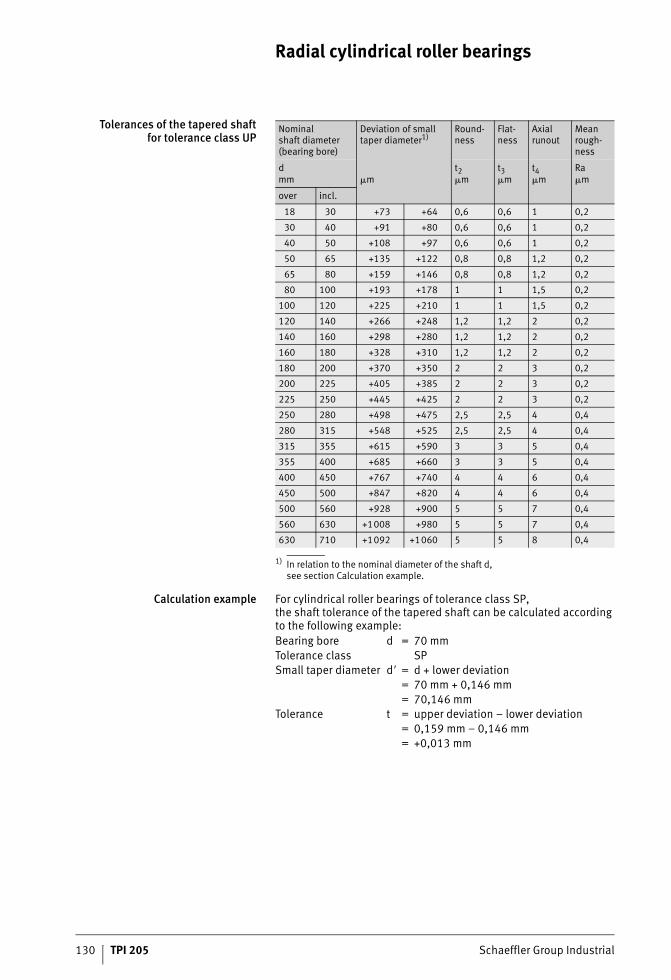
130 TPI 205 Schaeffler Group Industrial
Radial cylindrical roller bearings
Tolerances of the tapered shaftfor tolerance class UP
1) In relation to the nominal diameter of the shaft d,see section Calculation example.
Calculation example For cylindrical roller bearings of tolerance class SP,the shaft tolerance of the tapered shaft can be calculated according to the following example:
Nominalshaft diameter (bearing bore)
Deviation of small taper diameter1)
Round-ness
Flat-ness
Axial runout
Mean rough-ness
d t2 t3 t4 Ramm �m �m �m �m �m
over incl.
18 30 +73 +64 0,6 0,6 1 0,2
30 40 +91 +80 0,6 0,6 1 0,2
40 50 +108 +97 0,6 0,6 1 0,2
50 65 +135 +122 0,8 0,8 1,2 0,2
65 80 +159 +146 0,8 0,8 1,2 0,2
80 100 +193 +178 1 1 1,5 0,2
100 120 +225 +210 1 1 1,5 0,2
120 140 +266 +248 1,2 1,2 2 0,2
140 160 +298 +280 1,2 1,2 2 0,2
160 180 +328 +310 1,2 1,2 2 0,2
180 200 +370 +350 2 2 3 0,2
200 225 +405 +385 2 2 3 0,2
225 250 +445 +425 2 2 3 0,2
250 280 +498 +475 2,5 2,5 4 0,4
280 315 +548 +525 2,5 2,5 4 0,4
315 355 +615 +590 3 3 5 0,4
355 400 +685 +660 3 3 5 0,4
400 450 +767 +740 4 4 6 0,4
450 500 +847 +820 4 4 6 0,4
500 560 +928 +900 5 5 7 0,4
560 630 +1008 +980 5 5 7 0,4
630 710 +1092 +1060 5 5 8 0,4
Bearing bore d = 70 mmTolerance class SPSmall taper diameter d� = d + lower deviation
= 70 mm + 0,146 mm= 70,146 mm
Tolerance t = upper deviation – lower deviation= 0,159 mm – 0,146 mm= +0,013 mm
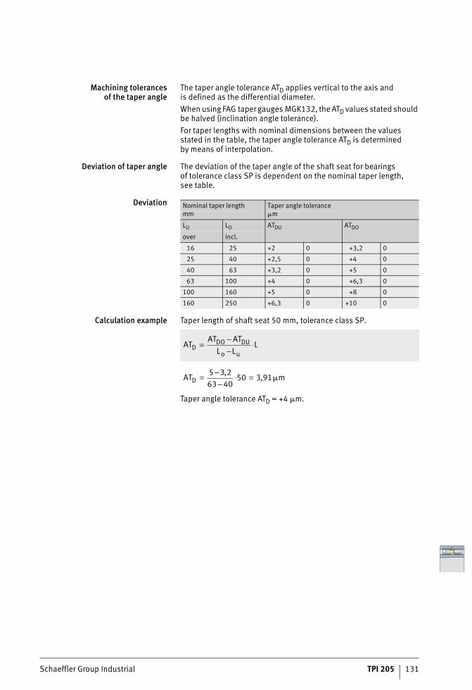
Schaeffler Group Industrial TPI 205 131
Machining tolerancesof the taper angle
The taper angle tolerance ATD applies vertical to the axis andis defined as the differential diameter.When using FAG taper gauges MGK132, the ATD values stated should be halved (inclination angle tolerance).For taper lengths with nominal dimensions between the values stated in the table, the taper angle tolerance ATD is determinedby means of interpolation.
Deviation of taper angle The deviation of the taper angle of the shaft seat for bearingsof tolerance class SP is dependent on the nominal taper length,see table.
Deviation
Calculation example Taper length of shaft seat 50 mm, tolerance class SP.
Taper angle tolerance ATD = +4 �m.
Nominal taper length Taper angle tolerancemm �m
LU LO ATDU ATDO
over incl.
16 25 +2 0 +3,2 0
25 40 +2,5 0 +4 0
40 63 +3,2 0 +5 0
63 100 +4 0 +6,3 0
100 160 +5 0 +8 0
160 250 +6,3 0 +10 0
ATAT AT
L LLD
DO DU
o u=
−−
⋅
AT mD = −−
⋅ =5 3 263 40
50 3 91,
, �
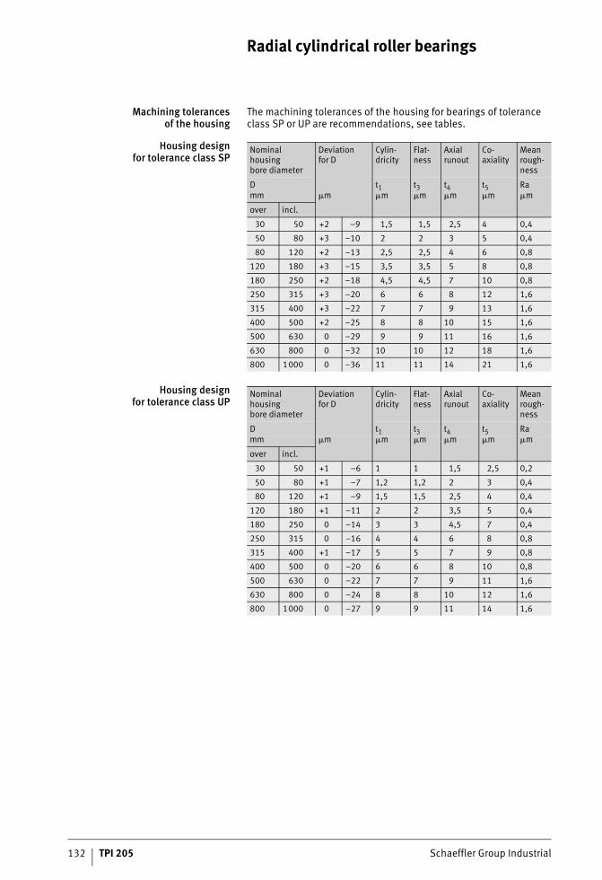
132 TPI 205 Schaeffler Group Industrial
Radial cylindrical roller bearings
Machining tolerancesof the housing
The machining tolerances of the housing for bearings of tolerance class SP or UP are recommendations, see tables.
Housing designfor tolerance class SP
Housing designfor tolerance class UP
Nominal housingbore diameter
Deviationfor D
Cylin-dricity
Flat-ness
Axial runout
Co-axiality
Mean rough-ness
D t1 t3 t4 t5 Ramm �m �m �m �m �m �m
over incl.
30 50 +2 –9 1,5 1,5 2,5 4 0,4
50 80 +3 –10 2 2 3 5 0,4
80 120 +2 –13 2,5 2,5 4 6 0,8
120 180 +3 –15 3,5 3,5 5 8 0,8
180 250 +2 –18 4,5 4,5 7 10 0,8
250 315 +3 –20 6 6 8 12 1,6
315 400 +3 –22 7 7 9 13 1,6
400 500 +2 –25 8 8 10 15 1,6
500 630 0 –29 9 9 11 16 1,6
630 800 0 –32 10 10 12 18 1,6
800 1000 0 –36 11 11 14 21 1,6
Nominal housingbore diameter
Deviationfor D
Cylin-dricity
Flat-ness
Axial runout
Co-axiality
Mean rough-ness
D t1 t3 t4 t5 Ramm �m �m �m �m �m �m
over incl.
30 50 +1 –6 1 1 1,5 2,5 0,2
50 80 +1 –7 1,2 1,2 2 3 0,4
80 120 +1 –9 1,5 1,5 2,5 4 0,4
120 180 +1 –11 2 2 3,5 5 0,4
180 250 0 –14 3 3 4,5 7 0,4
250 315 0 –16 4 4 6 8 0,8
315 400 +1 –17 5 5 7 9 0,8
400 500 0 –20 6 6 8 10 0,8
500 630 0 –22 7 7 9 11 1,6
630 800 0 –24 8 8 10 12 1,6
800 1000 0 –27 9 9 11 14 1,6
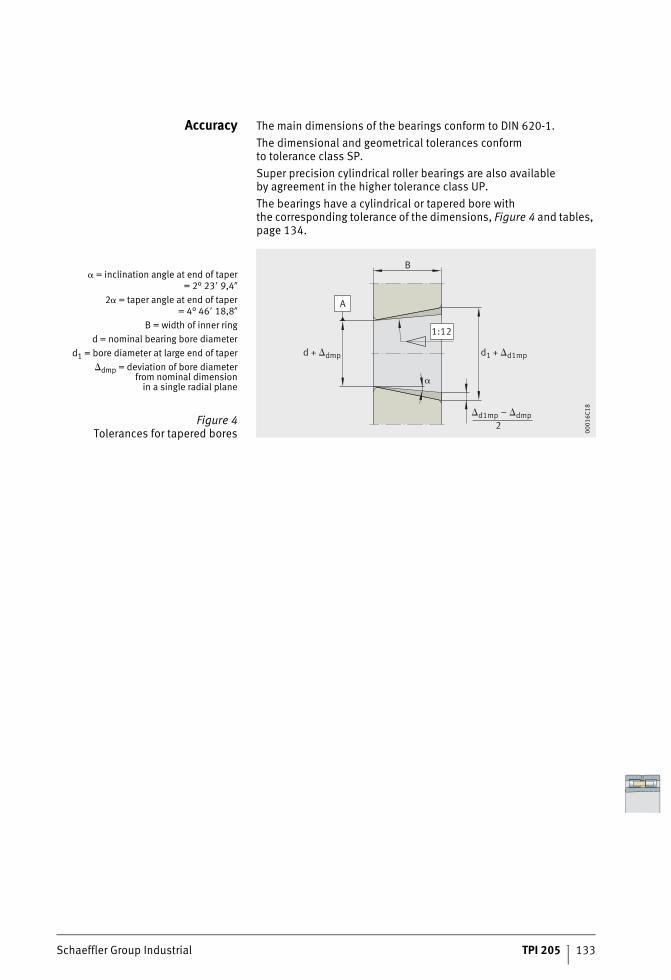
Schaeffler Group Industrial TPI 205 133
Accuracy The main dimensions of the bearings conform to DIN 620-1.The dimensional and geometrical tolerances conformto tolerance class SP.Super precision cylindrical roller bearings are also availableby agreement in the higher tolerance class UP.The bearings have a cylindrical or tapered bore withthe corresponding tolerance of the dimensions, Figure 4 and tables, page 134.
= inclination angle at end of taper= 2° 23� 9,4�
2 = taper angle at end of taper= 4° 46� 18,8�
B = width of inner ringd = nominal bearing bore diameter
d1 = bore diameter at large end of taperdmp = deviation of bore diameter
from nominal dimensionin a single radial plane
Figure 4Tolerances for tapered bores
B
2
d + dmp
d1 + d1mp
d1mp – dmp
A
1:12
0001
6C18
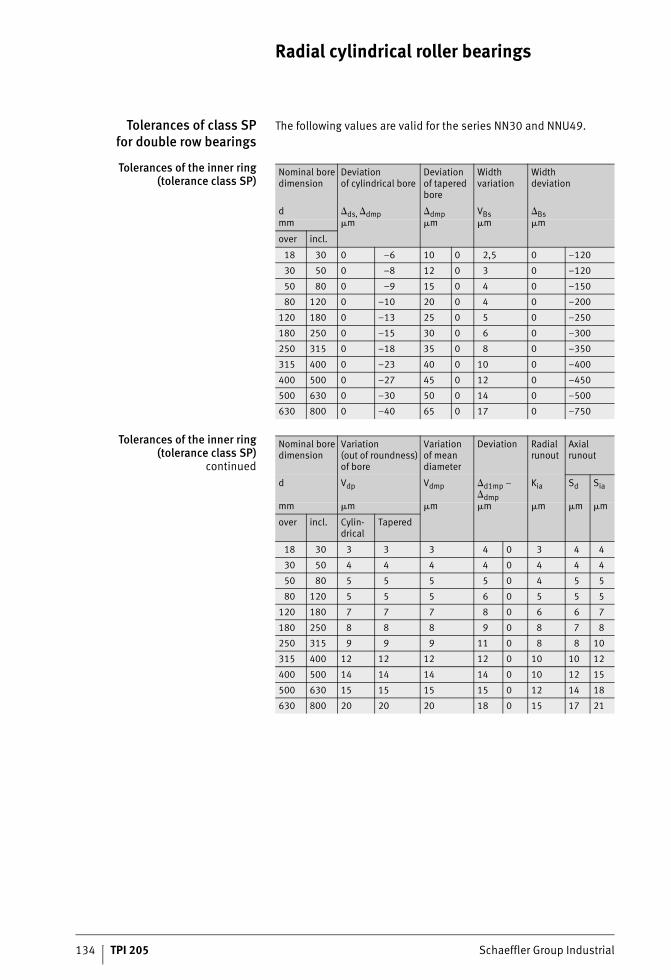
134 TPI 205 Schaeffler Group Industrial
Radial cylindrical roller bearings
Tolerances of class SPfor double row bearings
The following values are valid for the series NN30 and NNU49.
Tolerances of the inner ring(tolerance class SP)
Tolerances of the inner ring(tolerance class SP)
continued
Nominal bore dimension
Deviationof cylindrical bore
Deviationof tapered bore
Width variation
Widthdeviation
d ds, dmp dmp VBs Bsmm �m �m �m �m
over incl.
18 30 0 –6 10 0 2,5 0 –120
30 50 0 –8 12 0 3 0 –120
50 80 0 –9 15 0 4 0 –150
80 120 0 –10 20 0 4 0 –200
120 180 0 –13 25 0 5 0 –250
180 250 0 –15 30 0 6 0 –300
250 315 0 –18 35 0 8 0 –350
315 400 0 –23 40 0 10 0 –400
400 500 0 –27 45 0 12 0 –450
500 630 0 –30 50 0 14 0 –500
630 800 0 –40 65 0 17 0 –750
Nominal bore dimension
Variation(out of roundness) of bore
Variationof mean diameter
Deviation Radial runout
Axial runout
d Vdp Vdmp d1mp –dmp
Kia Sd Sia
mm �m �m �m �m �m �m
over incl. Cylin-drical
Tapered
18 30 3 3 3 4 0 3 4 4
30 50 4 4 4 4 0 4 4 4
50 80 5 5 5 5 0 4 5 5
80 120 5 5 5 6 0 5 5 5
120 180 7 7 7 8 0 6 6 7
180 250 8 8 8 9 0 8 7 8
250 315 9 9 9 11 0 8 8 10
315 400 12 12 12 12 0 10 10 12
400 500 14 14 14 14 0 10 12 15
500 630 15 15 15 15 0 12 14 18
630 800 20 20 20 18 0 15 17 21
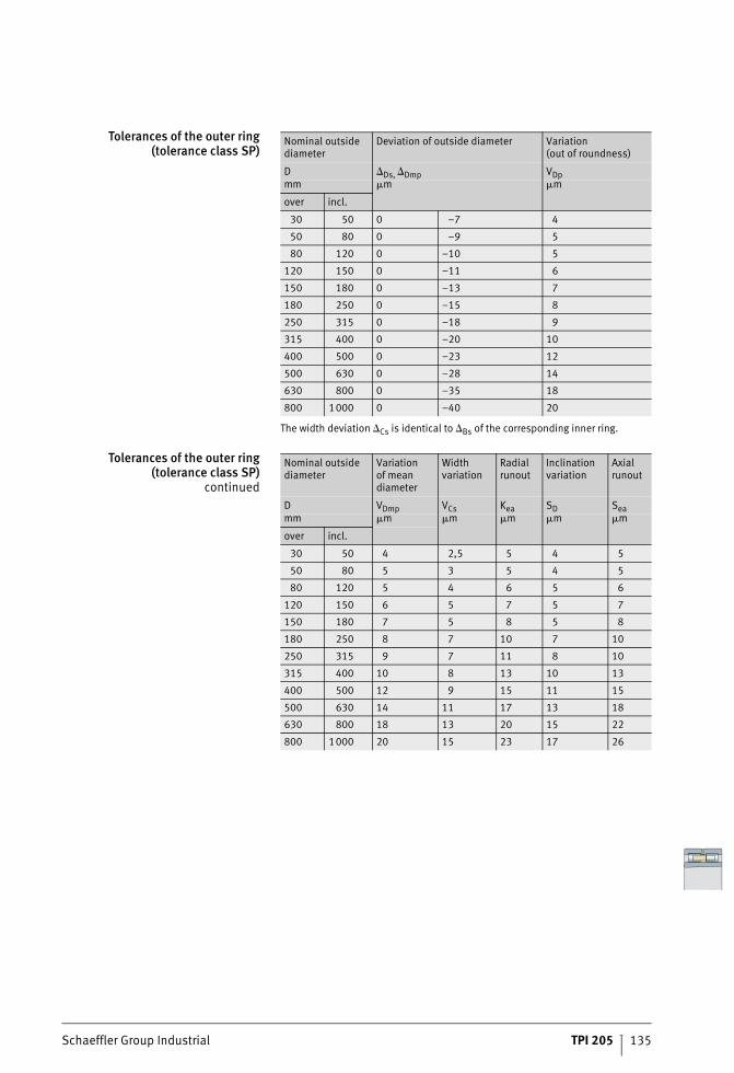
Schaeffler Group Industrial TPI 205 135
Tolerances of the outer ring(tolerance class SP)
The width deviation Cs is identical to Bs of the corresponding inner ring.
Tolerances of the outer ring(tolerance class SP)
continued
Nominal outside diameter
Deviation of outside diameter Variation(out of roundness)
D Ds, Dmp VDpmm �m �m
over incl.
30 50 0 –7 4
50 80 0 –9 5
80 120 0 –10 5
120 150 0 –11 6
150 180 0 –13 7
180 250 0 –15 8
250 315 0 –18 9
315 400 0 –20 10
400 500 0 –23 12
500 630 0 –28 14
630 800 0 –35 18
800 1000 0 –40 20
Nominal outside diameter
Variationof mean diameter
Width variation
Radial runout
Inclination variation
Axial runout
D VDmp VCs Kea SD Seamm �m �m �m �m �m
over incl.
30 50 4 2,5 5 4 5
50 80 5 3 5 4 5
80 120 5 4 6 5 6
120 150 6 5 7 5 7
150 180 7 5 8 5 8
180 250 8 7 10 7 10
250 315 9 7 11 8 10
315 400 10 8 13 10 13
400 500 12 9 15 11 15
500 630 14 11 17 13 18
630 800 18 13 20 15 22
800 1000 20 15 23 17 26
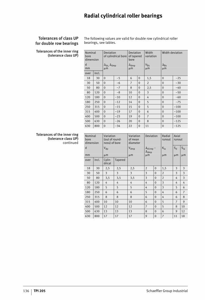
136 TPI 205 Schaeffler Group Industrial
Radial cylindrical roller bearings
Tolerances of class UPfor double row bearings
The following values are valid for double row cylindrical roller bearings, see tables.
Tolerances of the inner ring(tolerance class UP)
Tolerances of the inner ring(tolerance class UP)
continued
Nominal bore dimension
Deviationof cylindrical bore
Deviation of tapered bore
Width variation
Width deviation
d ds, dmp dmp VBs Bsmm �m �m �m �m
over incl.
18 30 0 –5 6 0 1,5 0 –25
30 50 0 –6 7 0 2 0 –30
50 80 0 –7 8 0 2,5 0 –40
80 120 0 –8 10 0 3 0 –50
120 180 0 –10 12 0 4 0 –60
180 250 0 –12 14 0 5 0 –75
250 315 0 –15 15 0 5 0 –100
315 400 0 –19 17 0 6 0 –100
400 500 0 –23 19 0 7 0 –100
500 630 0 –26 20 0 8 0 –125
630 800 0 –34 22 0 11 0 –125
Nominal bore dimension
Variation(out of round-ness) of bore
Variationof mean diameter
Deviation Radial runout
Axial runout
d Vdp Vdmp d1mp –dmp
Kia Sd Sia
mm �m �m �m �m �m�m
over incl. Cylin-drical
Tapered
18 30 2,5 2,5 2,5 2 0 1,5 3 3
30 50 3 3 3 3 0 2 3 3
50 80 3,5 3,5 3,5 3 0 2 4 3
80 120 4 4 4 4 0 3 4 4
120 180 5 5 5 4 0 3 5 6
180 250 6 6 6 5 0 4 6 7
250 315 8 8 8 6 0 4 6 8
315 400 10 10 10 6 0 5 7 9
400 500 12 12 12 7 0 5 8 10
500 630 13 13 13 8 0 6 9 12
630 800 17 17 17 9 0 7 11 18
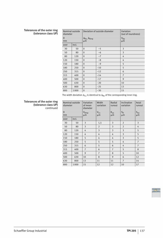
Schaeffler Group Industrial TPI 205 137
Tolerances of the outer ring(tolerance class UP)
The width deviation Cs is identical to Bs of the corresponding inner ring.
Tolerances of the outer ring(tolerance class UP)
continued
Nominal outside diameter
Deviation of outside diameter Variation(out of roundness)
D Ds, Dmp VDpmm �m �m
over incl.
30 50 0 –5 3
50 80 0 –6 3
80 120 0 –7 4
120 150 0 –8 4
150 180 0 –9 5
180 250 0 –10 5
250 315 0 –12 6
315 400 0 –14 7
400 500 0 –17 9
500 630 0 –20 10
630 800 0 –25 13
800 1000 0 –30 15
Nominal outside diameter
Variationof mean diameter
Width variation
Radial runout
Inclination variation
Axial runout
D VDmp VCs Kea SD Seamm �m �m �m �m �m
over incl.
30 50 3 1,5 3 2 3
50 80 3 2 3 2 4
80 120 4 3 3 3 5
120 150 4 4 4 3 5
150 180 5 4 4 3 5
180 250 5 5 5 4 7
250 315 6 5 6 4 7
315 400 7 6 7 5 8
400 500 9 7 8 5 10
500 630 10 8 9 6 12
630 800 13 11 11 7 14
800 1000 15 12 12 10 17
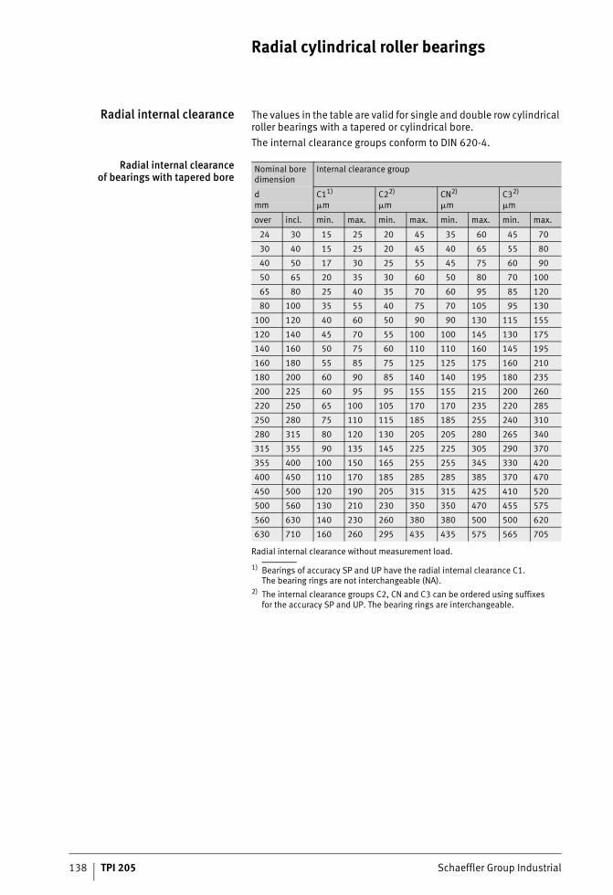
138 TPI 205 Schaeffler Group Industrial
Radial cylindrical roller bearings
Radial internal clearance The values in the table are valid for single and double row cylindrical roller bearings with a tapered or cylindrical bore.The internal clearance groups conform to DIN 620-4.
Radial internal clearanceof bearings with tapered bore
Radial internal clearance without measurement load.
1) Bearings of accuracy SP and UP have the radial internal clearance C1.The bearing rings are not interchangeable (NA).
2) The internal clearance groups C2, CN and C3 can be ordered using suffixesfor the accuracy SP and UP. The bearing rings are interchangeable.
Nominal bore dimension
Internal clearance group
d C11) C22) CN2) C32)
mm �m �m �m �m
over incl. min. max. min. max. min. max. min. max.
24 30 15 25 20 45 35 60 45 70
30 40 15 25 20 45 40 65 55 80
40 50 17 30 25 55 45 75 60 90
50 65 20 35 30 60 50 80 70 100
65 80 25 40 35 70 60 95 85 120
80 100 35 55 40 75 70 105 95 130
100 120 40 60 50 90 90 130 115 155
120 140 45 70 55 100 100 145 130 175
140 160 50 75 60 110 110 160 145 195
160 180 55 85 75 125 125 175 160 210
180 200 60 90 85 140 140 195 180 235
200 225 60 95 95 155 155 215 200 260
220 250 65 100 105 170 170 235 220 285
250 280 75 110 115 185 185 255 240 310
280 315 80 120 130 205 205 280 265 340
315 355 90 135 145 225 225 305 290 370
355 400 100 150 165 255 255 345 330 420
400 450 110 170 185 285 285 385 370 470
450 500 120 190 205 315 315 425 410 520
500 560 130 210 230 350 350 470 455 575
560 630 140 230 260 380 380 500 500 620
630 710 160 260 295 435 435 575 565 705
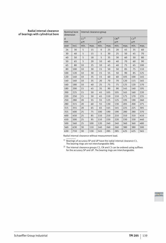
Schaeffler Group Industrial TPI 205 139
Radial internal clearanceof bearings with cylindrical bore
Radial internal clearance without measurement load.
1) Bearings of accuracy SP and UP have the radial internal clearance C1.The bearing rings are not interchangeable (NA).
2) The internal clearance groups C2, CN and C3 can be ordered using suffixesfor the accuracy SP and UP. The bearing rings are interchangeable.
Nominal bore dimension
Internal clearance group
d C11) C22) CN2) C32)
mm �m �m �m �m
over incl. min. max. min. max. min. max. min. max.
24 30 5 15 0 25 20 45 35 60
30 40 5 15 5 30 25 50 45 70
40 50 5 18 5 35 30 60 50 80
50 65 5 20 10 40 40 70 60 90
65 80 10 25 10 45 40 75 65 100
80 100 10 30 15 50 50 85 75 110
100 120 10 30 15 55 50 90 85 125
120 140 10 35 15 60 60 105 100 145
140 160 10 35 20 70 70 120 115 165
160 180 10 40 25 75 75 125 120 170
180 200 15 45 35 90 90 145 140 195
200 225 15 50 45 105 105 165 160 220
220 250 15 50 45 110 110 175 170 235
250 280 20 55 55 125 125 195 190 260
280 315 20 60 55 130 130 205 200 275
315 355 20 65 65 145 145 225 225 305
355 400 25 75 100 190 190 280 280 370
400 450 25 85 110 210 210 310 310 410
450 500 25 95 110 220 220 330 330 440
500 560 25 100 120 240 240 360 360 480
560 630 30 110 140 260 260 380 380 500
630 710 30 130 145 285 285 425 425 565
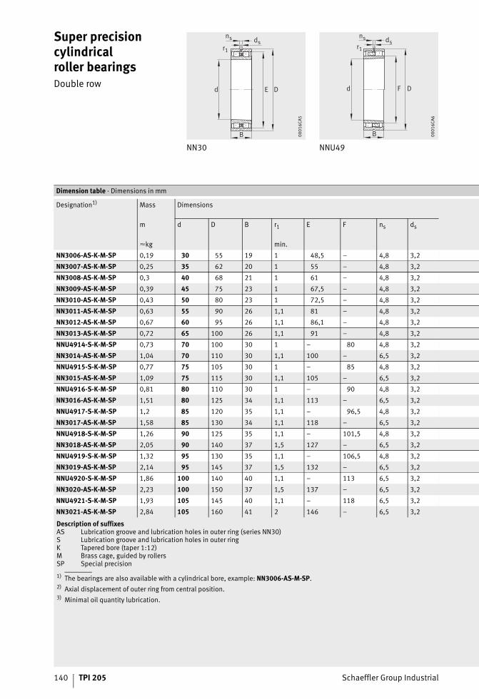
140 TPI 205 Schaeffler Group Industrial
Super precision cylindricalroller bearingsDouble row
NN30 NNU49
DE
r1
ns ds
d
B 0001
6CA5
d F D
B
r1
ns ds
0001
6CA6
1) The bearings are also available with a cylindrical bore, example: NN3006-AS-M-SP.2) Axial displacement of outer ring from central position.3) Minimal oil quantity lubrication.
Dimension table · Dimensions in mm
Designation1) Mass Dimensions
m d D B r1 E F ns ds
�kg min.
NN3006-AS-K-M-SP 0,19 30 55 19 1 48,5 – 4,8 3,2
NN3007-AS-K-M-SP 0,25 35 62 20 1 55 – 4,8 3,2
NN3008-AS-K-M-SP 0,3 40 68 21 1 61 – 4,8 3,2
NN3009-AS-K-M-SP 0,39 45 75 23 1 67,5 – 4,8 3,2
NN3010-AS-K-M-SP 0,43 50 80 23 1 72,5 – 4,8 3,2
NN3011-AS-K-M-SP 0,63 55 90 26 1,1 81 – 4,8 3,2
NN3012-AS-K-M-SP 0,67 60 95 26 1,1 86,1 – 4,8 3,2
NN3013-AS-K-M-SP 0,72 65 100 26 1,1 91 – 4,8 3,2
NNU4914-S-K-M-SP 0,73 70 100 30 1 – 80 4,8 3,2
NN3014-AS-K-M-SP 1,04 70 110 30 1,1 100 – 6,5 3,2
NNU4915-S-K-M-SP 0,77 75 105 30 1 – 85 4,8 3,2
NN3015-AS-K-M-SP 1,09 75 115 30 1,1 105 – 6,5 3,2
NNU4916-S-K-M-SP 0,81 80 110 30 1 – 90 4,8 3,2
NN3016-AS-K-M-SP 1,51 80 125 34 1,1 113 – 6,5 3,2
NNU4917-S-K-M-SP 1,2 85 120 35 1,1 – 96,5 4,8 3,2
NN3017-AS-K-M-SP 1,58 85 130 34 1,1 118 – 6,5 3,2
NNU4918-S-K-M-SP 1,26 90 125 35 1,1 – 101,5 4,8 3,2
NN3018-AS-K-M-SP 2,05 90 140 37 1,5 127 – 6,5 3,2
NNU4919-S-K-M-SP 1,32 95 130 35 1,1 – 106,5 4,8 3,2
NN3019-AS-K-M-SP 2,14 95 145 37 1,5 132 – 6,5 3,2
NNU4920-S-K-M-SP 1,86 100 140 40 1,1 – 113 6,5 3,2
NN3020-AS-K-M-SP 2,23 100 150 37 1,5 137 – 6,5 3,2
NNU4921-S-K-M-SP 1,93 105 145 40 1,1 – 118 6,5 3,2
NN3021-AS-K-M-SP 2,84 105 160 41 2 146 – 6,5 3,2
Description of suffixesAS Lubrication groove and lubrication holes in outer ring (series NN30)S Lubrication groove and lubrication holes in outer ringK Tapered bore (taper 1:12)M Brass cage, guided by rollersSP Special precision
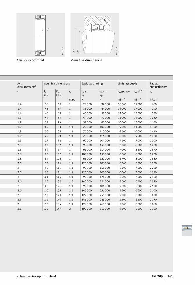
Schaeffler Group Industrial TPI 205 141
Axial displacement Mounting dimensions
s
0001
55E3
ra1
Da da
0001
6CA7
Axialdisplacement2)
Mounting dimensions Basic load ratings Limiting speeds Radialspring rigidity
s dah12
DaH12
ra1 dyn.Cr
stat.C0r
nG grease nG oil3) cr
max. N N min–1 min–1 N/�m
1,4 38 50 1 29 000 34 000 16 000 19 000 680
1,4 43 57 1 36 000 44 000 14 000 17 000 790
1,4 48 63 1 45 000 59 000 12 000 15 000 950
1,7 54 69 1 54 000 72 000 11 000 14 000 1 080
1,7 59 74 1 57 000 80 000 10 000 13 000 1 180
1,9 65 83 1,1 72 000 100 000 9 000 11 000 1 300
1,9 70 88 1,1 75 000 110 000 8 500 10 000 1 410
1,9 75 93 1,1 77 000 116 000 8 000 9 500 1 470
1,8 79 92 1 60 000 104 000 7 500 9 000 1 700
2,3 82 102 1,1 98 000 150 000 7 000 8 500 1 660
1,8 84 97 1 63 000 114 000 7 000 8 500 1 870
2,3 87 107 1,1 100 000 156 000 6 700 8 000 1 730
1,8 89 102 1 66 000 122 000 6 700 8 000 1 980
2,5 93 116 1,1 120 000 186 000 6 300 7 500 1 850
2 96 111 1,1 90 000 166 000 6 300 7 500 2 280
2,5 98 121 1,1 125 000 200 000 6 000 7 000 1 990
2 101 116 1,1 93 000 176 000 6 000 7 000 2 420
2,6 105 130 1,5 140 000 224 000 5 600 6 700 2 020
2 106 121 1,1 95 000 186 000 5 600 6 700 2 560
2,6 110 135 1,5 143 000 236 000 5 300 6 300 2 100
2 112 129 1,1 129 000 255 000 5 300 6 300 3 000
2,6 115 140 1,5 146 000 245 000 5 300 6 300 2 170
2 117 134 1,1 129 000 260 000 5 300 6 300 3 080
2,6 120 149 2 190 000 310 000 4 800 5 600 2 320
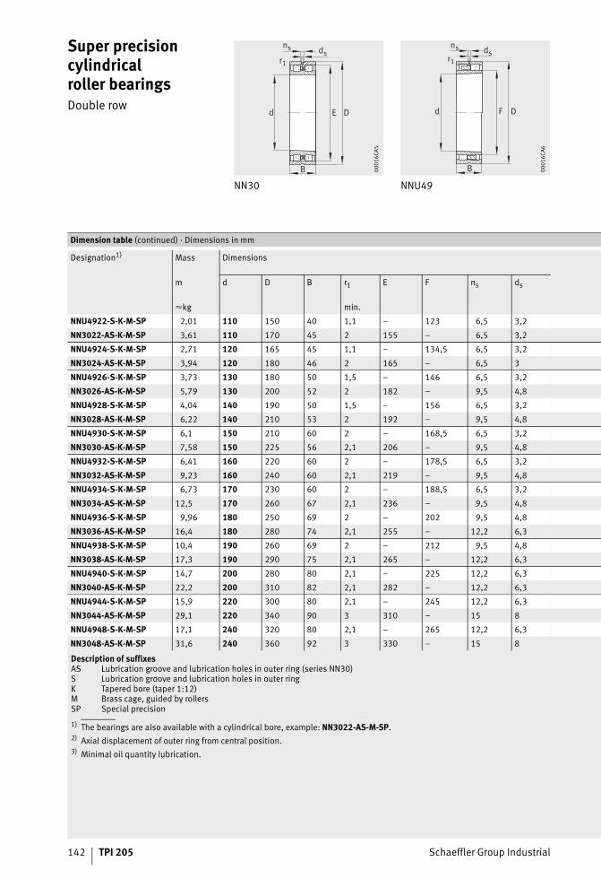
142 TPI 205 Schaeffler Group Industrial
Super precision cylindricalroller bearingsDouble row
NN30 NNU49
DE
r1
ns ds
d
B 0001
6CA5
d F D
B
r1
ns ds
0001
6CA6
1) The bearings are also available with a cylindrical bore, example: NN3022-AS-M-SP.2) Axial displacement of outer ring from central position.3) Minimal oil quantity lubrication.
Dimension table (continued) · Dimensions in mm
Designation1) Mass Dimensions
m d D B r1 E F ns ds
�kg min.
NNU4922-S-K-M-SP 2,01 110 150 40 1,1 – 123 6,5 3,2
NN3022-AS-K-M-SP 3,61 110 170 45 2 155 – 6,5 3,2
NNU4924-S-K-M-SP 2,71 120 165 45 1,1 – 134,5 6,5 3,2
NN3024-AS-K-M-SP 3,94 120 180 46 2 165 – 6,5 3
NNU4926-S-K-M-SP 3,73 130 180 50 1,5 – 146 6,5 3,2
NN3026-AS-K-M-SP 5,79 130 200 52 2 182 – 9,5 4,8
NNU4928-S-K-M-SP 4,04 140 190 50 1,5 – 156 6,5 3,2
NN3028-AS-K-M-SP 6,22 140 210 53 2 192 – 9,5 4,8
NNU4930-S-K-M-SP 6,1 150 210 60 2 – 168,5 6,5 3,2
NN3030-AS-K-M-SP 7,58 150 225 56 2,1 206 – 9,5 4,8
NNU4932-S-K-M-SP 6,41 160 220 60 2 – 178,5 6,5 3,2
NN3032-AS-K-M-SP 9,23 160 240 60 2,1 219 – 9,5 4,8
NNU4934-S-K-M-SP 6,73 170 230 60 2 – 188,5 6,5 3,2
NN3034-AS-K-M-SP 12,5 170 260 67 2,1 236 – 9,5 4,8
NNU4936-S-K-M-SP 9,96 180 250 69 2 – 202 9,5 4,8
NN3036-AS-K-M-SP 16,4 180 280 74 2,1 255 – 12,2 6,3
NNU4938-S-K-M-SP 10,4 190 260 69 2 – 212 9,5 4,8
NN3038-AS-K-M-SP 17,3 190 290 75 2,1 265 – 12,2 6,3
NNU4940-S-K-M-SP 14,7 200 280 80 2,1 – 225 12,2 6,3
NN3040-AS-K-M-SP 22,2 200 310 82 2,1 282 – 12,2 6,3
NNU4944-S-K-M-SP 15,9 220 300 80 2,1 – 245 12,2 6,3
NN3044-AS-K-M-SP 29,1 220 340 90 3 310 – 15 8
NNU4948-S-K-M-SP 17,1 240 320 80 2,1 – 265 12,2 6,3
NN3048-AS-K-M-SP 31,6 240 360 92 3 330 – 15 8
Description of suffixesAS Lubrication groove and lubrication holes in outer ring (series NN30)S Lubrication groove and lubrication holes in outer ringK Tapered bore (taper 1:12)M Brass cage, guided by rollersSP Special precision
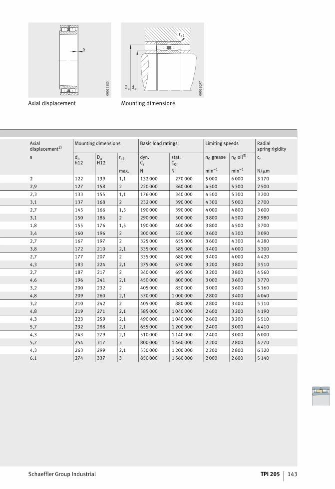
Schaeffler Group Industrial TPI 205 143
Axial displacement Mounting dimensions
s
0001
55E3
ra1
Da da
0001
6CA7
Axialdisplacement2)
Mounting dimensions Basic load ratings Limiting speeds Radialspring rigidity
s dah12
DaH12
ra1 dyn.Cr
stat.C0r
nG grease nG oil3) cr
max. N N min–1 min–1 N/�m
2 122 139 1,1 132 000 270 000 5 000 6 000 3 170
2,9 127 158 2 220 000 360 000 4 500 5 300 2 500
2,3 133 155 1,1 176 000 340 000 4 500 5 300 3 200
3,1 137 168 2 232 000 390 000 4 300 5 000 2 700
2,7 145 166 1,5 190 000 390 000 4 000 4 800 3 600
3,1 150 186 2 290 000 500 000 3 800 4 500 2 980
1,8 155 176 1,5 190 000 400 000 3 800 4 500 3 700
3,4 160 196 2 300 000 520 000 3 600 4 300 3 090
2,7 167 197 2 325 000 655 000 3 600 4 300 4 280
3,8 172 210 2,1 335 000 585 000 3 400 4 000 3 300
2,7 177 207 2 335 000 680 000 3 400 4 000 4 420
4,3 183 224 2,1 375 000 670 000 3 200 3 800 3 510
2,7 187 217 2 340 000 695 000 3 200 3 800 4 560
4,6 196 241 2,1 450 000 800 000 3 000 3 600 3 770
3,2 200 232 2 405 000 850 000 3 000 3 600 5 160
4,8 209 260 2,1 570 000 1 000 000 2 800 3 400 4 040
3,2 210 242 2 405 000 880 000 2 800 3 400 5 310
4,8 219 271 2,1 585 000 1 040 000 2 600 3 200 4 190
4,3 223 259 2,1 490 000 1 040 000 2 600 3 200 5 510
5,7 232 288 2,1 655 000 1 200 000 2 400 3 000 4 410
4,3 243 279 2,1 510 000 1 140 000 2 400 3 000 6 000
5,7 254 317 3 800 000 1 460 000 2 200 2 800 4 770
4,3 263 299 2,1 530 000 1 200 000 2 200 2 800 6 320
6,1 274 337 3 850 000 1 560 000 2 000 2 600 5 140

144 TPI 205 Schaeffler Group Industrial
Super precision cylindricalroller bearingsDouble row
NN30 NNU49
DE
r1
ns ds
d
B 0001
6CA5
d F D
B
r1
ns ds
0001
6CA6
1) The bearings are also available with a cylindrical bore, example: NN3052-AS-M-SP.2) Axial displacement of outer ring from central position.3) Minimal oil quantity lubrication.
Dimension table (continued) · Dimensions in mm
Designation1) Mass Dimensions
m d D B r1 E F ns ds
�kg min.
NNU4952-S-K-M-SP 29,7 260 360 100 2,1 – 292 15 8
NN3052-AS-K-M-SP 46,2 260 400 104 4 364 – 15 8
NNU4956-S-K-M-SP 31,6 280 380 100 2,1 – 312 15 8
NN3056-AS-K-M-SP 49,7 280 420 106 4 384 – 15 8
NNU4960-S-K-M-SP 49,1 300 420 118 3 – 339 17,7 9,5
NN3060-AS-K-M-SP 68,8 300 460 118 4 418 – 17,7 9,5
NNU4964-S-K-M-SP 51,8 320 440 118 3 – 359 17,7 9,5
NN3064-AS-K-M-SP 74,2 320 480 121 4 438 – 17,7 9
NNU4968-S-K-M-SP 54,5 340 460 118 3 – 379 17,7 9,5
NN3068-AS-K-M-SP 99,3 340 520 133 5 473 – 17,7 9,5
NNU4972-S-K-M-SP 57,3 360 480 118 3 – 399 17,7 9,5
NN3072-AS-K-M-SP 104 360 540 134 5 493 – 17,7 9,5
NNU4976-S-K-M-SP 85,8 380 520 140 4 – 426 17,7 9,5
NN3076-AS-K-M-SP 110 380 560 135 5 513 – 17,7 9,5
NNU4980-S-K-M-SP 89,4 400 540 140 4 – 446 17,7 9,5
NN3080-AS-K-M-SP 143 400 600 148 5 549 – 17,7 9,5
NNU4984-S-K-M-SP 93,2 420 560 140 4 – 466 17,7 9,5
NN3084-AS-K-M-SP 150 420 620 150 5 569 – 17,7 9,5
NNU4988-S-K-M-SP 129 440 600 160 4 – 490 17,7 9,5
NN3088-AS-K-M-SP 172 440 650 157 6 597 – 23,5 12,5
NNU4992-S-K-M-SP 134 460 620 160 4 – 510 17,7 9,5
NN3092-AS-K-M-SP 197 460 680 163 6 624 – 23,5 12,5
NNU4996-S-K-M-SP 158 480 650 170 5 – 534 17,7 9,5
NN3096-AS-K-M-SP 206 480 700 165 6 644 – 23,5 12,5
NNU49/500-S-K-M-SP 162 500 670 170 5 – 568 17,7 9,5
NN30/500-AS-K-M-SP 214 500 720 167 6 664 – 23,5 12
Description of suffixesAS Lubrication groove and lubrication holes in outer ring (series NN30)S Lubrication groove and lubrication holes in outer ringK Tapered bore (taper 1:12)M Brass cage, guided by rollersSP Special precision
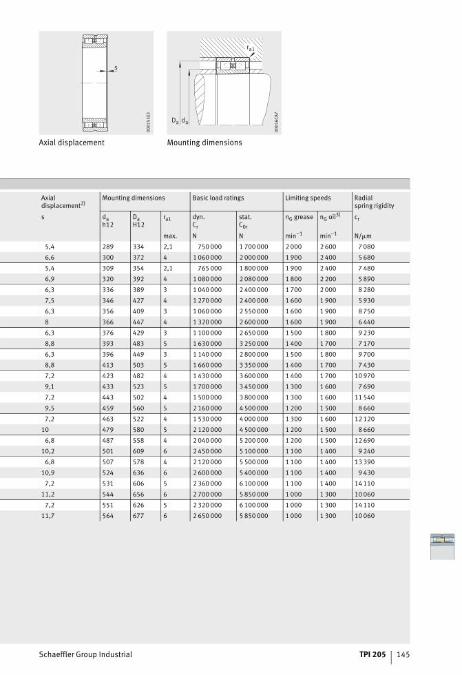
Schaeffler Group Industrial TPI 205 145
Axial displacement Mounting dimensions
s
0001
55E3
ra1
Da da
0001
6CA7
Axialdisplacement2)
Mounting dimensions Basic load ratings Limiting speeds Radialspring rigidity
s dah12
DaH12
ra1 dyn.Cr
stat.C0r
nG grease nG oil3) cr
max. N N min–1 min–1 N/�m
5,4 289 334 2,1 750 000 1 700 000 2 000 2 600 7 080
6,6 300 372 4 1 060 000 2 000 000 1 900 2 400 5 680
5,4 309 354 2,1 765 000 1 800 000 1 900 2 400 7 480
6,9 320 392 4 1 080 000 2 080 000 1 800 2 200 5 890
6,3 336 389 3 1 040 000 2 400 000 1 700 2 000 8 280
7,5 346 427 4 1 270 000 2 400 000 1 600 1 900 5 930
6,3 356 409 3 1 060 000 2 550 000 1 600 1 900 8 750
8 366 447 4 1 320 000 2 600 000 1 600 1 900 6 440
6,3 376 429 3 1 100 000 2 650 000 1 500 1 800 9 230
8,8 393 483 5 1 630 000 3 250 000 1 400 1 700 7 170
6,3 396 449 3 1 140 000 2 800 000 1 500 1 800 9 700
8,8 413 503 5 1 660 000 3 350 000 1 400 1 700 7 430
7,2 423 482 4 1 430 000 3 600 000 1 400 1 700 10 970
9,1 433 523 5 1 700 000 3 450 000 1 300 1 600 7 690
7,2 443 502 4 1 500 000 3 800 000 1 300 1 600 11 540
9,5 459 560 5 2 160 000 4 500 000 1 200 1 500 8 660
7,2 463 522 4 1 530 000 4 000 000 1 300 1 600 12 120
10 479 580 5 2 120 000 4 500 000 1 200 1 500 8 660
6,8 487 558 4 2 040 000 5 200 000 1 200 1 500 12 690
10,2 501 609 6 2 450 000 5 100 000 1 100 1 400 9 240
6,8 507 578 4 2 120 000 5 500 000 1 100 1 400 13 390
10,9 524 636 6 2 600 000 5 400 000 1 100 1 400 9 430
7,2 531 606 5 2 360 000 6 100 000 1 100 1 400 14 110
11,2 544 656 6 2 700 000 5 850 000 1 000 1 300 10 060
7,2 551 626 5 2 320 000 6 100 000 1 000 1 300 14 110
11,7 564 677 6 2 650 000 5 850 000 1 000 1 300 10 060
Equipment and servicesfor the mounting and maintenanceof rolling bearings
Schaeffler Group Industrial TPI 205 147
Page
Equipment and services for the mounting and maintenance of rolling bearings
Equipment and services Competence in maintenance................................................... 148
Services to industry ................................................................ 148
Products for mounting and repair............................................ 149
Products for condition monitoring........................................... 151
Mounting service.................................................................... 152
Condition Monitoring.............................................................. 152
Rolling bearing reconditioning ................................................ 153
148 TPI 205 Schaeffler Group Industrial
Equipment and services for the mounting and maintenance of rolling bearings
Equipment and servicesCompetence in maintenance The service arm of Schaeffler Group Industrial is the specialist
contact for the maintenance of rotating components.The aim is to help customers save on maintenance costs, optimise plant availability and avoid unforeseen machine downtime.The services are provided irrespective of the brand of the machine components used.In order to ensure rapid, competent supply of maintenance products and services to customers worldwide, the Schaeffler Group has centres of competence all over the world. All service employees undergo a comprehensive training programme and are audited regularly. This ensures that all services throughout the world conform to a uniformly high standard of quality. Since each customer has a different set of requirements, the Schaeffler Group offers concepts individually tailored to the customer.
Services to industry The service function has undertaken ongoing expansion of its range in recent years. A small excerpt from the extensive range of products and services can be seen in the following sections.Detailed information on the equipment and services available can be found in Catalogue IS1, Mounting and Maintenance of Rolling Bearings.
Enquiries If you have any questions on equipment and services,please address these directly to the service function:■ E-mail: [email protected]■ Internet: www.schaeffler-iam.com■ Telephone: +49 (0)2407 9149-66
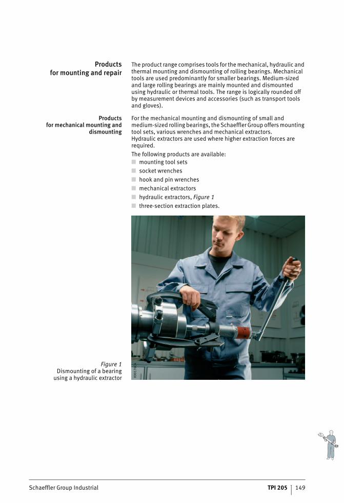
Schaeffler Group Industrial TPI 205 149
Productsfor mounting and repair
The product range comprises tools for the mechanical, hydraulic and thermal mounting and dismounting of rolling bearings. Mechanical tools are used predominantly for smaller bearings. Medium-sized and large rolling bearings are mainly mounted and dismounted using hydraulic or thermal tools. The range is logically rounded offby measurement devices and accessories (such as transport tools and gloves).
Productsfor mechanical mounting and
dismounting
For the mechanical mounting and dismounting of small and medium-sized rolling bearings, the Schaeffler Group offers mounting tool sets, various wrenches and mechanical extractors.Hydraulic extractors are used where higher extraction forces are required.The following products are available:■ mounting tool sets■ socket wrenches■ hook and pin wrenches■ mechanical extractors■ hydraulic extractors, Figure 1■ three-section extraction plates.
Figure 1Dismounting of a bearing
using a hydraulic extractor 0001
76C4
150 TPI 205 Schaeffler Group Industrial
Equipment and services for the mounting and maintenance of rolling bearings
Productsfor hydraulic mounting and
dismounting
In order to give easier mounting and dismounting of bearings witha tapered bore, hydraulic nuts are often used. Pressure generation devices available include oil injectors, hand pump sets andhigh pressure pumps. Selection is aided by the software Mounting Manager.There is a comprehensive range of accessories, such as man-ometers, adapters and reduction nipples, high pressure hoses and sleeve connectors:■ hydraulic nuts■ oil injectors■ hand pump sets■ high pressure pumps■ hydraulic systems and units■ connectors, accessories.
Productsfor thermal mounting and
dismounting
Rapid and energy-efficient heating of rolling bearings can be achieved with induction heating devices.The Schaeffler Group has table top equipment for mobile useas well as high performance standalone equipment:■ electric heating plates■ induction heating devices■ heating rings, heat conducting paste■ electric induction heating devices.
Productsfor measurement and
inspection
Feeler gauges and measuring devices can be used to checkthe production of bearing seats and the mounting of bearings:■ feeler gauges■ taper gauges■ snap gauges■ enveloping circle gauges.
Accessoriesfor mounting and
dismounting
Accessories provide assistance in the storage, transport and mounting of rolling bearings:■ transport and mounting tools■ gloves■ mounting paste■ anti-corrosion oil.
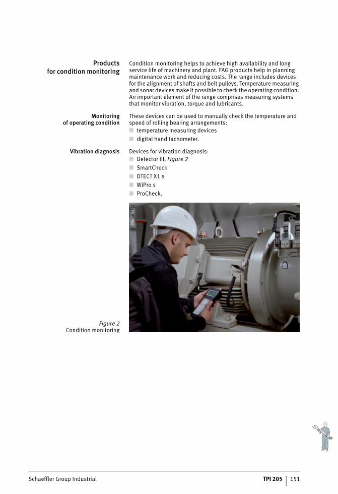
Schaeffler Group Industrial TPI 205 151
Productsfor condition monitoring
Condition monitoring helps to achieve high availability and long service life of machinery and plant. FAG products help in planning maintenance work and reducing costs. The range includes devices for the alignment of shafts and belt pulleys. Temperature measuring and sonar devices make it possible to check the operating condition. An important element of the range comprises measuring systems that monitor vibration, torque and lubricants.
Monitoringof operating condition
These devices can be used to manually check the temperature and speed of rolling bearing arrangements:■ temperature measuring devices■ digital hand tachometer.
Vibration diagnosis Devices for vibration diagnosis:■ Detector III, Figure 2■ SmartCheck■ DTECT X1 s■ WiPro s■ ProCheck.
Figure 2Condition monitoring
0001
76C5
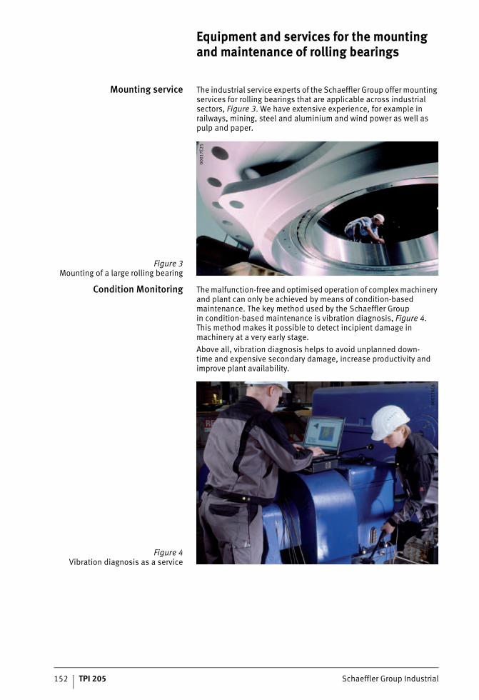
152 TPI 205 Schaeffler Group Industrial
Equipment and services for the mounting and maintenance of rolling bearings
Mounting service The industrial service experts of the Schaeffler Group offer mounting services for rolling bearings that are applicable across industrial sectors, Figure 3. We have extensive experience, for example in railways, mining, steel and aluminium and wind power as well as pulp and paper.
Condition Monitoring The malfunction-free and optimised operation of complex machinery and plant can only be achieved by means of condition-based maintenance. The key method used by the Schaeffler Groupin condition-based maintenance is vibration diagnosis, Figure 4.This method makes it possible to detect incipient damage in machinery at a very early stage.Above all, vibration diagnosis helps to avoid unplanned down-time and expensive secondary damage, increase productivity and improve plant availability.
Figure 3Mounting of a large rolling bearing
0001
7E25
Figure 4Vibration diagnosis as a service
0001
76C6
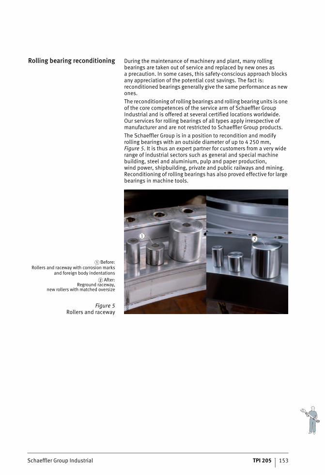
Schaeffler Group Industrial TPI 205 153
Rolling bearing reconditioning During the maintenance of machinery and plant, many rolling bearings are taken out of service and replaced by new ones asa precaution. In some cases, this safety-conscious approach blocks any appreciation of the potential cost savings. The fact is: reconditioned bearings generally give the same performance as new ones.The reconditioning of rolling bearings and rolling bearing units is one of the core competences of the service arm of Schaeffler Group Industrial and is offered at several certified locations worldwide.Our services for rolling bearings of all types apply irrespective of manufacturer and are not restricted to Schaeffler Group products.The Schaeffler Group is in a position to recondition and modify rolling bearings with an outside diameter of up to 4 250 mm, Figure 5. It is thus an expert partner for customers from a very wide range of industrial sectors such as general and special machine building, steel and aluminium, pulp and paper production,wind power, shipbuilding, private and public railways and mining. Reconditioning of rolling bearings has also proved effective for large bearings in machine tools.
� Before:Rollers and raceway with corrosion marks
and foreign body indentations� After:
Reground raceway,new rollers with matched oversize
Figure 5Rollers and raceway 00
0171
FB
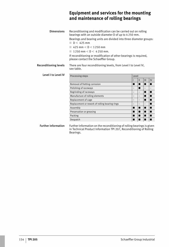
154 TPI 205 Schaeffler Group Industrial
Equipment and services for the mounting and maintenance of rolling bearings
Dimensions Reconditioning and modification can be carried out on rolling bearings with an outside diameter D of up to 4 250 mm. Bearings and bearing units are divided into three diameter groups:■ D � 425 mm■ 425 mm � D � 1250 mm■ 1250 mm � D � 4 250 mm.If reconditioning or modification of other bearings is required, please contact the Schaeffler Group.
Reconditioning levels There are four reconditioning levels, from Level I to Level IV,see table.
Level I to Level IV
Further information Further information on the reconditioning of rolling bearings is given in Technical Product Information TPI 207, Reconditioning of Rolling Bearings.
Processing steps Level
I II III IV
Removal of fretting corrosion ■ ■ ■ ■
Polishing of raceways – ■ – –
Regrinding of raceways – – ■ ■
Manufacture of rolling elements – – ■ ■
Replacement of cage – – ■ ■
Replacement or rework of rolling bearing rings – – – ■
Assembly ■ ■ ■ ■
Preservation or greasing ■ ■ ■ ■
Packing ■ ■ ■ ■
Despatch ■ ■ ■ ■
Schaeffler Group Industrial TPI 205 155
Addresses
GermanySchaeffler TechnologiesGmbH & Co. KGIndustriestraße 1–391074 HerzogenaurachGermanyTel. +(49) 91 32 / 82-0Fax +(49) 91 32 / [email protected]
Schaeffler TechnologiesGmbH & Co. KGGeorg-Schäfer-Straße 3097421 SchweinfurtGermanyTel. +(49) 97 21 / 91 0Fax +(49) 97 21 / 91 34 35 [email protected]
ArgentinaSchaeffler Argentina S.r.l.Av. Alvarez Jonte 1938C1416EXR Buenos AiresArgentinaTel. +(54) 11 / 40 16 15 00Fax +(54) 11 / 45 82 33 [email protected]
AustraliaSchaeffler Australia Pty LimitedLevel 1, Bldg 8,Forest Central Business Park49 Frenchs Forest RoadFrenchs Forest, NSW 2086AustraliaTel. +(61) 2 8977 1000Fax +(61) 2 9452 [email protected]
AustriaSchaeffler Austria GmbHFerdinand-Pölzl-Straße 22560 Berndorf-St. VeitAustriaTel. +43 2672 202-0Fax +43 2672 [email protected]
BelarusSchaeffler KGRepräsentanz WeißrusslandOdoewskogo 117, Raum 317220015, MinskBelarusTel. +(375) 17 269 94 81Fax +(375) 17 269 94 [email protected]
BelgiumSchaeffler Belgium S.P.R.L./B.V.B.A.Avenue du Commerce, 381420 Braine L‘AlleudBelgiumTel. +(32) 2 / 3 89 13 89Fax +(32) 2 / 3 89 13 99 [email protected]
Bosnia-HerzegovinaSchaeffler Hrvatska d.o.o.Ogrizovićeva 28b10000 ZagrebCroatiaTel. +(385) 1 37 01 943Fax +(385) 1 37 64 [email protected]
BrazilSchaeffler Brasil Ltda.Av. Independência, 3500-ABairro Éden18087-101 Sorocaba, SP BrazilTel. +(55) 0800 11 10 29Fax +(55) 15 / 33 35 19 [email protected]
BulgariaSchaeffler Bulgaria OODDondukov-Blvd. No 62Eing. A, 6. Etage, App. 101504 SofiaBulgariaTel. +359 2 946 3900
+359 2 943 4008Fax +359 2 943 [email protected]
CanadaSchaeffler Canada Inc.Canada Oakville2871 Plymouth DriveOakville, ON L6H 5S5 CanadaTel. +(1) 905 / 8 29 27 50Tel. +(1) 800-263-4397 Toll FreeFax +(1) 905 / 8 29 25 [email protected]
ChinaSchaeffler Holding (China) Co., Ltd.No. 1 Antuo Road (west side of Anhong Road)Anting, Jiading District201804 ShanghaiChinaTel. +86 21 3957 6500Fax +86 21 3957 6600www.schaeffler.cn
Schaeffler Trading (Shanghai) Co., Ltd. Beijing BranchRM 2801, Nexus Center, No. 19 AEast 3rd Ring Road North, Chaoyang District100020 BeijingChinaTel. +86 10 6515 0288Fax +86 10 6512 [email protected]
Schaeffler (China) Co., Ltd.18 Chaoyang Road, TaicangJiangsu Province215400 Taicang , JiangsuChinaTel. +86 512 5395 7700Fax +86 512 5357 [email protected]
156 TPI 205 Schaeffler Group Industrial
Addresses
Czech RepublicSchaeffler CZ s.r.o. Průběžná 74a100 00 Praha 10Czech RepublicTel. +420 267 298 111Fax +420 267 298 [email protected]
DenmarkSchaeffler Danmark ApSJens Baggesens Vej 90P8200 Århus NDenmarkTel. +(45) 70 15 44 44Fax +(45) 70 15 22 [email protected]
EstoniaSchaeffler TechnologiesRepräsentanz BaltikumDuntes iela 23a1005 RigaLatviaTel. +(371) 7 06 37 95Fax +(371) 7 06 37 [email protected]
FinlandSchaeffler Finland OyLautamiehentie 302770 EspooFinlandTel. +(358) 207 / 36 6204Fax +(358) 207 36 [email protected]
FranceSchaeffler France93, route de Bitche, BP 3018667506 HaguenauFranceTel. +(33) 3 88 63 40 40 Fax +(33) 3 88 63 40 [email protected]
Great BritainSchaeffler (UK) LtdForge Lane, MinworthSutton ColdfieldWest Midlands B76 1APGreat BritainTel. +(44) 121 3 13 58 70Fax +(44) 121 3 13 00 [email protected]
HungarySchaeffler Magyarország Ipari Kft.Neuman János út 1/B fsz.1117 BudapestHungaryTel. +(36) 1 / 4 81 30 50Fax +(36) 1 / 4 81 30 [email protected]
IndiaFAG Bearings India LimitedManejaVadodara 390 013IndiaTel. +91 265 26426-51/-52Fax +91 265 2 63 88-04/[email protected]
FAG Bearings India Limited# 18, Gr. Floor, Wst View 77,R.V. Road, BasavanagudiBangalore 560 004 IndiaTel. +91 80 2657 5120/-4866Fax +91 80 [email protected]
INA Bearings India Pvt. Ltd.Site No. 1, Sri Nrusimha Towers,First Floor,Amruthnagar Main RoadNext to Sub-registrar's Office, KonanakunteBangalore, 560 062IndiaTel. +91 80 4260 6999Fax +91 80 4260 [email protected]
INA Bearings India Pvt. Ltd.Plot No. A-3 Talegaon Industrial & Floriculture ParkVillage Ambi, Navalakha Umbre, Taluka MavalPune 410 507IndiaTel. +91 20 306104104Fax +91 20 [email protected]
ItalySchaeffler Italia S.r.l.Strada Provinciale 229 Km 1728015 MomoItalyTel. +(39) 3 21 / 92 92 11Fax +(39) 3 21 / 92 93 [email protected]
JapanSchaeffler Japan Co., Ltd.New Stage Yokohama1-132, Shinurashima-cho, Kanagawa-ku,Yokohama, 221-0031,JapanTel. +81 45 274 8211Fax +81 45 274 [email protected]
KoreaSchaeffler Korea Corporation -Schaeffler Ansan Corporation1054-2 Shingil-dong, Ansan-shi,Kyonggi-do, 425-020KoreaTel. +(82) 31 / 4 90 69 11Fax +(82) 31 / 4 94 38 [email protected]
LuxembourgSchaeffler Belgium S.P.R.L./B.V.B.A.Avenue du Commerce, 381420 Braine L‘AlleudBelgiumTel. +(32) 2 / 3 89 13 89Fax +(32) 2 / 3 89 13 99 [email protected]
MalaysiaSchaeffler Bearings (Malaysia) Sdn. Bhd.5-2 Wisma Fiamma, No. 20 Jalan 7A/62A Bandar Menjalara52200 Kuala LumpurMalaysiaTel. +(60) 3-6275 0620Fax +(60) 3 6275 [email protected]
MexicoINA México, S.A. de C.V. -Rodamientos FAG, S.A. de C.V.Henry Ford #141Col. BondojitoDeleg. Gustavo A. Madero07850 Mexico D.F.Mexico Tel. +(52) 55 5062 6085Fax +(52) 55 57 39 58 [email protected]
NetherlandsSchaeffler Nederland B.V.Gildeweg 313771 NB BarneveldNetherlandsTel. +(31) 342 / 40 30 00Fax +(31) 342 / 40 32 [email protected]
New ZealandSchaeffler New Zealand(Unit R, Cain Commercial Centre)20 Cain Road1135 PenroseNew ZealandTel. +(64) 9 583 1280Tel. +64 021 324 247
(Call out fee applies)Fax +(64) 9 583 [email protected]
Schaeffler Group Industrial TPI 205 157
NorwaySchaeffler Norge ASGrenseveien 1070663 OsloNorwayTel. +(47) 23 24 93 30 Fax +(47) 23 24 93 [email protected]
PolandSchaeffler Polska Sp. z.o.o.Budynek Eul. Szyszkowa 35/3702-285 WarszawaPolandTel. +(48) 22 / 8 78 41 20Fax +(48) 22 / 8 78 41 [email protected]
PortugalINA Rolamentos Lda.Arrábida Lake TowersRua Daciano Baptista Marques Torre C,181, 2º piso4400-617 Vila Nova de GaiaPortugalTel. +(351) 22 / 5 32 08 00Fax +(351) 22 / 5 32 08 [email protected]
RomaniaS.C. Schaeffler Romania S.R.L.Aleea Schaeffler Nr. 3507055 Cristian/BrasovRomaniaTel. +(40) 268 505808Fax +(40) 268 [email protected]
RussiaSchaeffler Russland GmbH Leningradsky Prospekt 47, Bau 3Business-Center Avion125167 MoscowRussia Tel. +7 495 7 37 76 60Fax +7 495 7 37 76 [email protected]
SerbiaSchaeffler TechnologiesRepräsentanz SerbienBranka Krsmanovica 1211118 BeogradSerbiaTel. +(381) 11 308 87 82Fax +(381) 11 308 87 [email protected]
SingaporeSchaeffler (Singapore) Pte. Ltd.151 Lorong Chuan, #06-01New Tech Park, Lobby A556741 SingaporeSingaporeTel. +(65) 6540 8600Fax +(65) 6540 [email protected]
Slovak RepublicSchaeffler Slovensko, spol. s.r.o.Ulica Dr. G. Schaefflera 102401 Kysucké Nové MestoSlovak Republic Tel. +(421) 41 / 4 20 59 11Fax +(421) 41 / 4 20 59 [email protected]
SloveniaSchaeffler Slovenija d.o.o.Glavni trg 17/b2000 MariborSloveniaTel. +(386) 2 / 22 82-070Fax +(386) 2 / 22 [email protected]
South AfricaSchaeffler South Africa (Pty.) Ltd.1 End Street Ext. Corner Heidelberg Road2000 JohannesburgSouth AfricaTel. +(27) 11 225 3000Fax +(27) 11 334 [email protected]
SpainSchaeffler Iberia, s.l.u.Polígono Ind. Pont Reixat08960 Sant Just DesvernSpainTel. +(34) 93 / 4 80 34 10Fax +(34) 93 / 3 72 92 [email protected]
SwedenSchaeffler Sverige ABCharles gata 10195 61 ArlandastadSwedenTel. +(46) 8 / 59 51 09 00Fax +(46) 8 / 59 51 09 [email protected]
SwitzerlandHYDREL GmbHBadstrasse 148590 RomanshornSwitzerlandTel. +(41) 71 / 4 66 66 66Fax +(41) 71 / 4 66 63 [email protected]
TaiwanSchaeffler Taiwan Co.9F-6 No.188 Sec.5, Nanjing E. Road, 105TaipeiTaiwanTel. +886 2 7707 9888Fax +886 2 2747 [email protected]
TurkeySchaeffler Rulmanlari Ticaret LimitedSirketi Aydin Sokak Dagli Apt. 4/41. Levent34340 IstanbulTurkeyTel. +90 212 2 79 27 41Tel. +90 212 280 77 98Fax +90 212 2 81 66 45Fax +90 212 280 94 [email protected]
UkraineSchaeffler TechnologiesRepresentative Office UkraineJilyanskayastr. 75, 5-er StockBusiness Center «Eurasia»01032 KiewUkraineTel. +(380) 44-593-02-81Fax +(380) 44-593-02-83 [email protected]
USASchaeffler Group USA Inc.308 Springhill Farm RoadFort Mill, SC 29715 USATel. +1 803 548 8500Fax +1 803 548 [email protected]
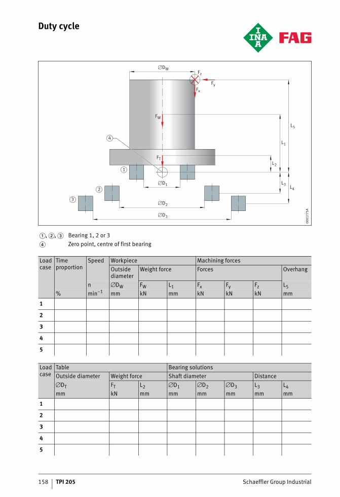
158 TPI 205 Schaeffler Group Industrial
Duty cycle
�, �, � Bearing 1, 2 or 3� Zero point, centre of first bearing
Load case
Time proportion
Speed Workpiece Machining forcesOutside diameter
Weight force Forces Overhang
n �DW FW L1 Fx Fy Fz L5% min–1 mm kN mm kN kN kN mm
1
2
3
4
5
Load case
Table Bearing solutionsOutside diameter Weight force Shaft diameter Distance�DT FT L2 �D1 �D2 �D3 L3 L4mm kN mm mm mm mm mm mm
1
2
3
4
5
L5
L4L3�D1
�D2
�DW
�D3
L1
L2
FT
FW
Fz
FyFx
2
1
3
4
0001
775A

Notes
Schaeffler Group Industrial TPI 205 159

160 TPI 205 Schaeffler Group Industrial
Notes
MAT
NR
0368
8893
1-00
00 /
TPI 2
05 /
GB-
D /
2011
051
/ Prin
ted
in G
erm
any
by h
ofm
ann
Schaeffler Technologies GmbH & Co. KG
Industriestraße 1 – 3 91074 Herzogenaurach Germany Internet www.ina.com E-mail [email protected]
In Germany: Phone 0180 5003872 Fax 0180 5003873
From other countries: Phone +49 9132 82-0 Fax +49 9132 82-4950
Schaeffler Technologies GmbH & Co. KG
Georg-Schäfer-Straße 30 97421 Schweinfurt Germany Internet www.fag.com E-mail [email protected]
In Germany: Phone 0180 5003872 Fax 0180 5003873
From other countries: Phone +49 9721 91-0 Fax +49 9721 91-3435
Every care has been taken to ensure the
correctness of the information contained
in this publication but no liability can be
accepted for any errors or omissions.
We reserve the right to make technical
changes.
© Schaeffler Technologies GmbH & Co. KG
Issued: 2011, May
This publication or parts thereof may not
be reproduced without our permission.
TPI 205 GB-D