Embed Size (px)
Citation preview
1
07CONTENTSFAN COOLED BRAKE………………….….2FAN COOLED BRAK DBR 250……….…..3Airtek NAC Clutches………………….……4Airtek NAB-T Brakes……………….…...…6Airtek NAB-S Brakes.………………….…..8CALIPER Pneumatic Disc Brakes……….9DBF DISC BRAKE CALIPER..……….......10DBG DISC BRAKE CALIPER…..….….….11DBH DISC BRAKE CALIPER..……….…..12DBH DISC BRAKE CALIPER..……….…..13DSH Spring applied Air release..…...…..14DBZ- DISC BRAKES..…………………..…15DBM Pneumatic / Hydraulic Caliper…....16BST BOOSTER CYLINDER ……..........…17DISC D230-D260…...……………...........…18DISC-D400-D500…………………..........…19SAFETY CHUCKS…….……….................20MOUNTING attention.……………….....…21PIO/W FLO/W19………………………....…22PIO/W FLO/W28………………………....…23PIO/W FLO/W35………………………....…24PIO/W FLO/W50………………………....…25PIO/W75…………………..……………....…26AIR SHAFT………………..……………...…27TYPE OF AIR SHAFT……..………...…..…28Quotation sheet for Air Shaft………....…29SPRING APPLY MECHANICAL CHUCK.....…30ROTARY MEACHANICAL CHUCK..........…31STEPPED MACHANICAL CHUCK.......…32
QUALITY IS OUR FIRST PRIOITY
PNEUMATIC ADAPTER…..………..…....…33HOLLOW MECHANICAL CHUCK….…..…35FLANGE HOLLOW CHUCK………….……36AIR DIFFERENTIAL SHAFT………….……37MECHANICAL DIFFERENTIAL SHAFT.…38Powder Brake POB 006~400 series.....….39Powder Clutch POC 006~400 series........40Powder PHB 050~100 series....................41Powder PHC 050~100 series....................42Powder POB 0.05~0.5 series....................43Powder POC 0.2~010 series.....................44TC-608P TENSIONCONTROLLER………………..................….451040 LOAD CELL…………………..........….46VA-816………………………………..........….47POWDER BRAKES CONTROLLER......….48Examples of connecting circuit…............49E/P Converter….........................................50INTRODUCTION OF EDGE GUIDECONTROLLER……………………...........….51HC-2A AUTO EDGE GUIDE CONTROLLER………………………………………...........….52HC-HEI AUTO PHOTO ELECTRIC EDGECONTROLLER……………………...........….53HC-5AM EDGE GUIDE CONTROLLERAUTO / MANUAL…………………...........….54EDGE GUIDE INSTALLATION…….............55ELECTRIC WEB GUIDE.........................….57EPC/LPC SENSORS…..........................…..58
2
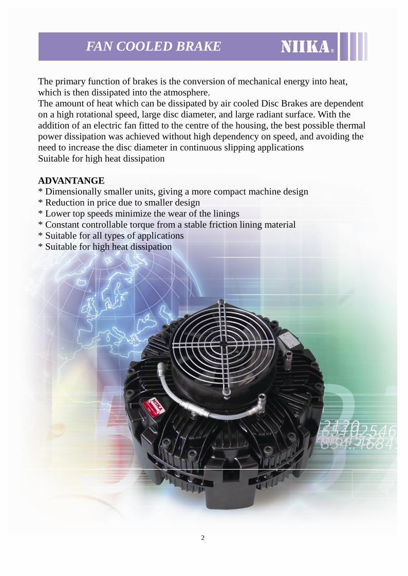
FAN COOLED BRAKE
The primary function of brakes is the conversion of mechanical energy into heat,which is then dissipated into the atmosphere.The amount of heat which can be dissipated by air cooled Disc Brakes are dependenton a high rotational speed, large disc diameter, and large radiant surface. With theaddition of an electric fan fitted to the centre of the housing, the best possible thermalpower dissipation was achieved without high dependency on speed, and avoiding theneed to increase the disc diameter in continuous slipping applicationsSuitable for high heat dissipation
ADVANTANGE* Dimensionally smaller units, giving a more compact machine design* Reduction in price due to smaller design* Lower top speeds minimize the wear of the linings* Constant controllable torque from a stable friction lining material* Suitable for all types of applications* Suitable for high heat dissipation
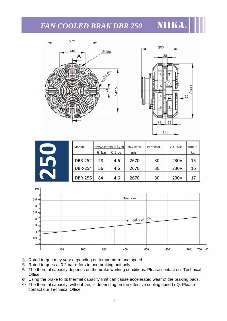
FAN COOLED BRAK DBR 250 ※ Rated torque may vary depending on temperature and speed. ※ Rated torques at 0.2 bar refers to one braking unit only. ※ The thermal capacity depends on the brake working conditions. Please contact our Technical
Office. ※ Using the brake to its thermal capacity limit can cause accelerated wear of the braking pads. ※ The thermal capacity, without fan, is depending on the effective cooling speed nQ. Please
contact our Technical Office.
3
4
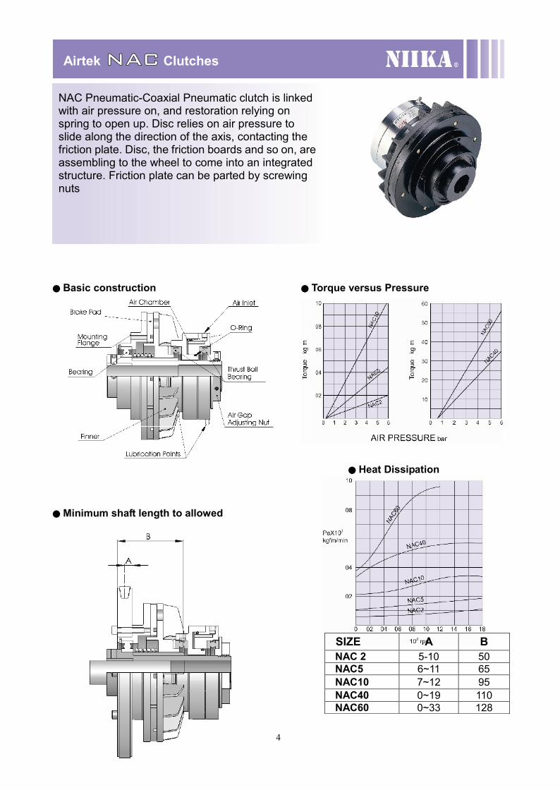
AirtekNAC Clutches
● Basic construction ● Torque versus Pressure
● Heat Dissipation
●Minimum shaft length to allowed
SIZE A BNAC 2 5-10 50NAC5 6~11 65NAC10 7~12 95NAC40 0~19 110NAC60 0~33 128
NAC Pneumatic-Coaxial Pneumatic clutch is linkedwith air pressure on, and restoration relying onspring to open up. Disc relies on air pressure toslide along the direction of the axis, contacting thefriction plate. Disc, the friction boards and so on, areassembling to the wheel to come into an integratedstructure. Friction plate can be parted by screwingnuts
5
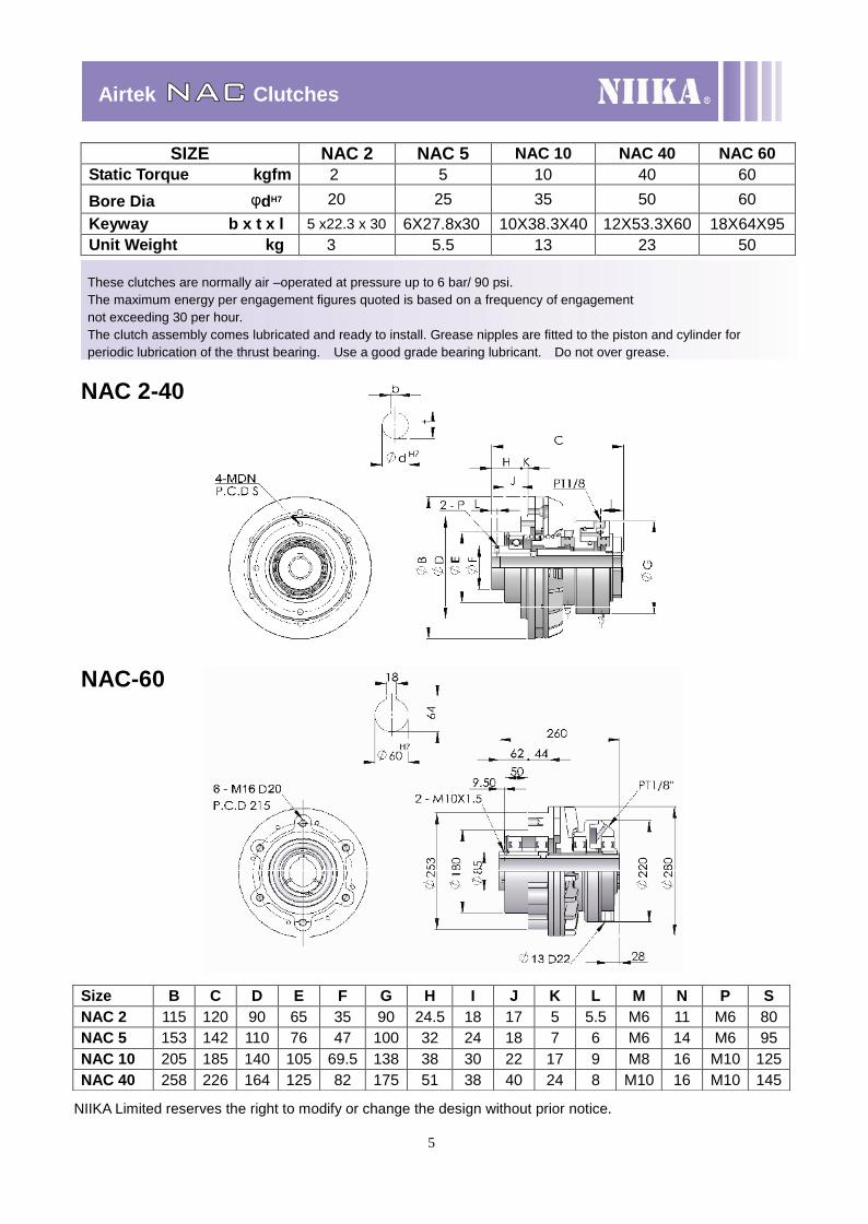
AirtekNAC Clutches
These clutches are normally air –operated at pressure up to 6 bar/ 90 psi.The maximum energy per engagement figures quoted is based on a frequency of engagementnot exceeding 30 per hour.The clutch assembly comes lubricated and ready to install. Grease nipples are fitted to the piston and cylinder forperiodic lubrication of the thrust bearing. Use a good grade bearing lubricant. Do not over grease.
NAC 2-40
NAC-60
SIZE NAC 2 NAC 5 NAC 10 NAC 40 NAC 60Static Torque kgfm 2 5 10 40 60
Bore Dia φdH7 20 25 35 50 60Keyway b x t x l 5 x22.3 x 30 6X27.8x30 10X38.3X40 12X53.3X60 18X64X95Unit Weight kg 3 5.5 13 23 50
Size B C D E F G H I J K L M N P SNAC 2 115 120 90 65 35 90 24.5 18 17 5 5.5 M6 11 M6 80NAC 5 153 142 110 76 47 100 32 24 18 7 6 M6 14 M6 95NAC 10 205 185 140 105 69.5 138 38 30 22 17 9 M8 16 M10 125NAC 40 258 226 164 125 82 175 51 38 40 24 8 M10 16 M10 145
NIIKA Limited reserves the right to modify or change the design without prior notice.
6
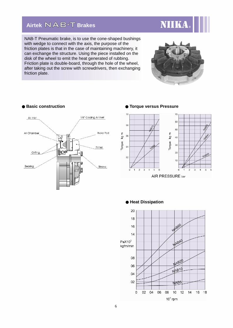
AirtekNAB-T Brakes
● Basic construction ● Torque versus Pressure
● Heat Dissipation
NAB-T Pneumatic brake, is to use the cone-shaped bushingswith wedge to connect with the axis, the purpose of thefriction plates is that in the case of maintaining machinery, itcan exchange the structure. Using the piece installed on thedisk of the wheel to emit the heat generated of rubbing.Friction plate is double-board, through the hole of the wheel,after taking out the screw with screwdrivers, then exchangingfriction plate.
7
AirtekNAB-T Brakes
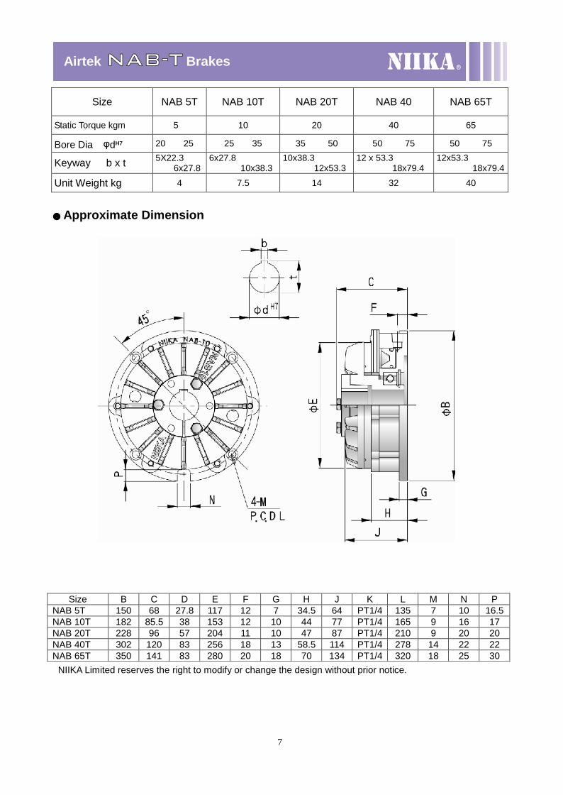
Size NAB 5T NAB 10T NAB 20T NAB 40 NAB 65T
Static Torque kgm 5 10 20 40 65
Bore Dia φdH7 20 25 25 35 35 50 50 75 50 75
Keyway b x t 5X22.36x27.8
6x27.810x38.3
10x38.312x53.3
12 x 53.318x79.4
12x53.318x79.4
Unit Weight kg 4 7.5 14 32 40
●Approximate Dimension
Size B C D E F G H J K L M N PNAB 5T 150 68 27.8 117 12 7 34.5 64 PT1/4 135 7 10 16.5NAB 10T 182 85.5 38 153 12 10 44 77 PT1/4 165 9 16 17NAB 20T 228 96 57 204 11 10 47 87 PT1/4 210 9 20 20NAB 40T 302 120 83 256 18 13 58.5 114 PT1/4 278 14 22 22NAB 65T 350 141 83 280 20 18 70 134 PT1/4 320 18 25 30
NIIKA Limited reserves the right to modify or change the design without prior notice.
8
AirtekNAB-S Brakes
Size NAB 5S NAB 10SStatic Torque kgm 5 10Bore Dia φdH7 25 25 35Keyway b x t 6x27.8 6x27.8 10x38.3Unit Weight kg 4 7.5
Mounting Example
Size B C E F G H J K L M N PNAB 5S 150 65 117 12 7 34.5 64 PT1/4 135 7 10 16.5NAB 10S 182 82 153 12 10 44 77 PT1/4 165 9 16 17
NAB 5S-10S
9
CALIPER Pneumatic / Hydraulic disc brades
Stable performance of the disc brakes which withstand frequent uses.These brakes do not require an adjustment while they are in use, and their repairs are simple.While their braking forces may be arbitrarily adjusted, the range of braking force is widened.These brakes are resistant to dust and wetting, and withstand high ambient temperatures.Their prices are low, and their deliveries are made promptly.
● Calculation on the braking torque
Braking torque
T = 2 μ A P r
r = 0.5 d-0.03
Stopping time
nl nl n GD2
t B = —————————— = —————————— = —————————
30TN 60μAPrN 120 TgN
Disc temperatureThe disc temperature goes up at the time of braking. Although in many cases, the temperature
need not be taken into account, when rotary bodies involving large energies are frequently braked,or when this brake is continuously used as a constant torque brake, the normal workingtemperature of the disc should be calculated according to the following equation lest, 200 ay beexceeded at all times .
a. Braking objects in linear motion
WV2
E = ——————— X ƒ2g
T : Braking torque per one brake kg-mμ : efficient of friction. μ0.3A : Area of cylinder cm2P : Operating pressure kg / cm2r: Effective braking radius m
d : Outside diameter of disc m
tB : Stopping time secI : GD2 / 4g Moment of inertia kg m sec2
n : Number of initial revolutions rpmN : Number of brakes used at the same timeg : 9.8 m / sec2
E : Energy generated kg m / minW : Weight kgV : Speed m / secƒ : Braking frequency rpm / min
g : 9.8 m / sec2
10
DBFDISC BRAKES CALIPER air applied spring released
The DBF is a type of small brake which bottom is stationary,adapts differently way of installation,Also can use in the brake of beeline movement.Big friction area can extend the cycle of maintenance and long life.If it installs certain brakes on one disc, torque also enlargealong with it certain time
The DBF series disk brake is suitable for all thickness of the disc bychanging the special spacer.
● Torque versus Pressure
Standard DBF for disc thickness 10 mm but can modify to suit disc thickness up to 15MM.
APPROXIMATE DIMENSION
Size DBF 10
Maximum air pressure 7 kg/cm2
Braking force 5 kg/cm2 μ=0.33 64 kgf
Areas of cylinders 19.63 cm2
Disc O. D. mm 220↑
Disc thickness 10 mm
Unit Weight 2 kg
Warning : The initial torque on new units can be 30% to 50% less then the catalogue value until thefriction facing and friction disc are lapped or worn in.
NIIKA Limited reserves the right to modify or change the design without prior notice.
11
DBGDISC BRAKES CALIPER air applied spring released
As a type of economical brake, it can provide stably and effective power of braking.The vertical installation can saves the space and the heat of rubbing surface can dissipate rapidly.The friction part is easy to replace, and it does not contain any asbestos,Brake-disc thickness covers from 10mm to 20mm.To control the deceleration of moving parts for smalland medium powers, the best solution is the combination ofa brake disc with one or more pneumatic calipers.
Torque Formula : Braking Torque (kgm) =Braking Force(kg) x Effective Disc Radius (Actual)(mm)
Size DBG 104 DBG 105
Maximum under overload 7 kg/cm2 7 kg/cm2
Compression ratio 0.74 0.74
Disc thickness 10 mm 10 mm
Disc O. D. mm 200↑ 200↑
Unit Weight 5.5 kg 6 kg
Size X Y φZDBG 104 18 145 142DBG 105 36 160 177
Warning : The initial torque on new units can be 30% to 50% less then the catalogue value until thefriction facing and friction disc are lapped or worn in.
NIIKA Limited reserves the right to modify or change the design without prior notice.
● Torque versus Pressure
APPROXIMATE DIMENSION
DBG 10 M

12
DBHDISC BRAKES CALIPER air applied spring released
The type brake is for horizontal-type installation,it can provides approximately 2 timesof braking powder than vertical installation.Add the expandable shrapnel to guarantee the brake balance,The friction part is easy to replace, and it does not contain any asbestos,To control the deceleration of moving parts for smalland medium powers, the best solution is the combination ofa brake disc with one or more pneumatic calipers.
Torque Formula : Braking Torque (kgm) =Braking Force(kg) x Effective Disc Radius (Actual)(mm)
● Torque versus Pressure
APPROXIMATE DIMENSION RIGHT TYPE
Size DBH 104 DBH 105
Maximum under overload 7 kg/cm2 7 kg/cm2
Compression ratio 1.83 1.83
Disc thickness 10 mm 10 mm
Disc O. D. mm 200↑ 200↑
Unit Weight 8.5 kg 9 kg
Size X Y φZ
DBH 104 132 267.5 142
DBH 105 152 285 177
Every horizontal caliper separate into the left and right type.Please indicate left or right side type when order.
Warning : The initial torque on new units can be 30% to 50% less then the catalogue value until thefriction facing and friction disc are lapped or worn in.
NIIKA Limited reserves the right to modify or change the design without prior notice.
LEFTTYPE
13
DBHDISC BRAKES CALIPER air applied spring released
The type brake is for horizontal-type installation,it can provides approximately 2 timesof braking powder than vertical installation.Add the expandable shrapnel to guarantee the brake balance,The friction part is easy to replace, and it does not contain any asbestos,To control the deceleration of moving parts for smalland medium powers, the best solution is the combination ofa brake disc with one or more pneumatic calipers.
Torque Formula : Braking Torque (kgm) =Braking Force(kg) x Effective Disc Radius (Actual)(mm)
● Torque versus PressureSize DBH 204 DBH 205
Maximum under overload 7 kg/cm2 7 kg/cm2
Compression ratio 1.83 1.83
Disc thickness 20 mm 20 mm
Disc O. D. mm 200↑ 200↑
Unit Weight 9 kg 9.5 kg
Size X Y φZ
DBH 204 135 267.5 142
DBH 205 155 285 177
Every horizontal caliper separate into the left and right type.Please indicate left or right side type when order.
Warning : The initial torque on new units can be 30% to 50% less then the catalogue value until thefriction facing and friction disc are lapped or worn in.
NIIKA Limited reserves the right to modify or change the design without prior notice.
APPROXIMATE DIMENSION RIGHT TYPE
LEFTTYPE
14
DSH FAIL SAFE BRAKESPRING APPLIED AIR RELEASE
A spring-applied fail safe brake for dry-running, which can be used for both holding and RIGHT TYPEdynamic applications. All types of Fail-Safe brakes therefore are offered with pneumaticreleased but emergency release by means of manual lever or integrated screws.Furthermore the amount of maintenance required for both the compressedair supply system and for the pneumatic brakes is small.
Torque Formula : Braking Torque (kgm) =Braking Force(kg) x Effective Disc Radius (Actual)(mm)
● Torque versus PressureModel DSH 205
DISC THICKNESS 20 MMMAX AIR PRESSUREkg/cm2 7
DISC OD MM 260↑
WEIGHT 19 KGS
APPROXIMATE DIMENSION LEFT TYPE
15
DBZ-06A DISC BRAKAIR Disc Brake
As a type of small brake, the installation is flexible, can save more installation space. Application of torquecontrol and brake maintenance specially adapt to the light loading condition. Convenient for release of heatand maintenance, we can supply the model of manual control.
DBZ-10A AIR Disc Brake
DBZ-06M MANUAL DISC BRAKE
TORQUE VERSUS PRESSURE
16
DBM Pneumatic / Hydraulic Caliper
DBM oil hydraulic disc brake is mainly power by brakes oil,and can also power by air-actuated matched with hydraulic booster.
The ordinary brakes fluid is required (DOT3, DOT4 or above)
The DBM brakes do not require an adjustment while they are in use,and it’s repairs are simple.The DBM brake brakes are resistant to dust and wetting, and withstandhigh ambient temperatures.
DBM brake separate into left and right type, which depends onposition of oil- inlet. Please indicate left or right side typewhen order.
● Torque versus Pressure
RIGHT TYPE
Size A B C D E F G H K L N P R SDBM 10 135 118 40 34 51 50 2 40 10 150 34 110 350 30DBM 20 145 128 50 34 51 50 2 40 20 150 34 110 30
Size DBM 10 DBM 20Sizes of cylinders 2 1/8” 2 1/8”Area of cylinders 22.88 cm2 22.88 cm2
Amount of operating Oil About 2.5cc About 2.5ccNormal working 50 kg/cm2 50 kg/cm2Operating oil
pressuresMaximum 70 kg/cm2 70 kg/cm2
Disc thickness 10 mm 20 mmDisc O. D. mm 200↑ 200↑Unit Weight 5 kg 5.5 kg
DBM brake separate into left and right type, which depends onposition of oil- inlet. Please indicate left or right side type whenorder.
DIMENSION
Warning : The initial torque on new units can be 30% to 50% less then the catalogue value until thefriction facing and friction disc are lapped or worn in.
NIIKA Limited reserves the right to modify or change the design without prior notice.
LEFTTYPE
17
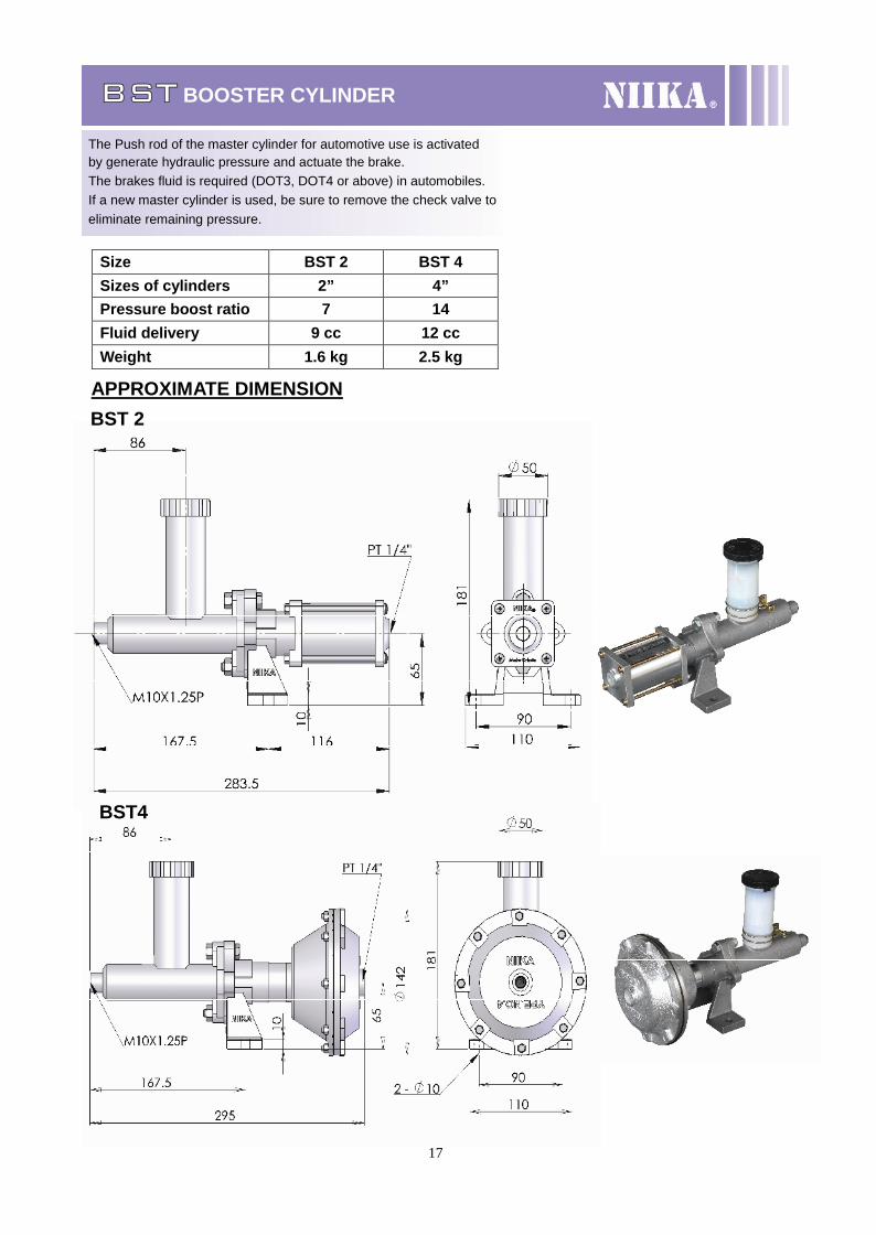
BST BOOSTER CYLINDER
The Push rod of the master cylinder for automotive use is activatedby generate hydraulic pressure and actuate the brake.The brakes fluid is required (DOT3, DOT4 or above) in automobiles.If a new master cylinder is used, be sure to remove the check valve toeliminate remaining pressure.
APPROXIMATE DIMENSIONBST 2
BST4
Size BST 2 BST 4Sizes of cylinders 2” 4”Pressure boost ratio 7 14Fluid delivery 9 cc 12 ccWeight 1.6 kg 2.5 kg
18
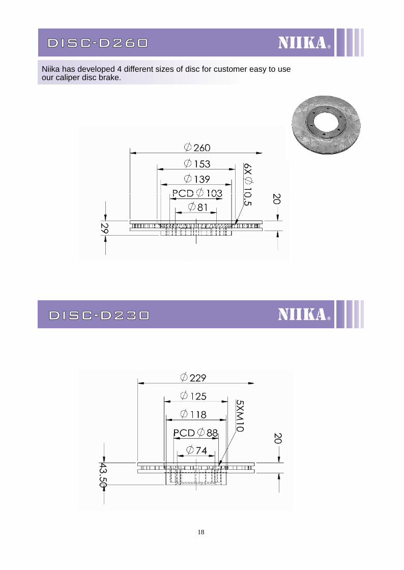
DISC-D260
Niika has developed 4 different sizes of disc for customer easy to useour caliper disc brake.
DISC-D230
19
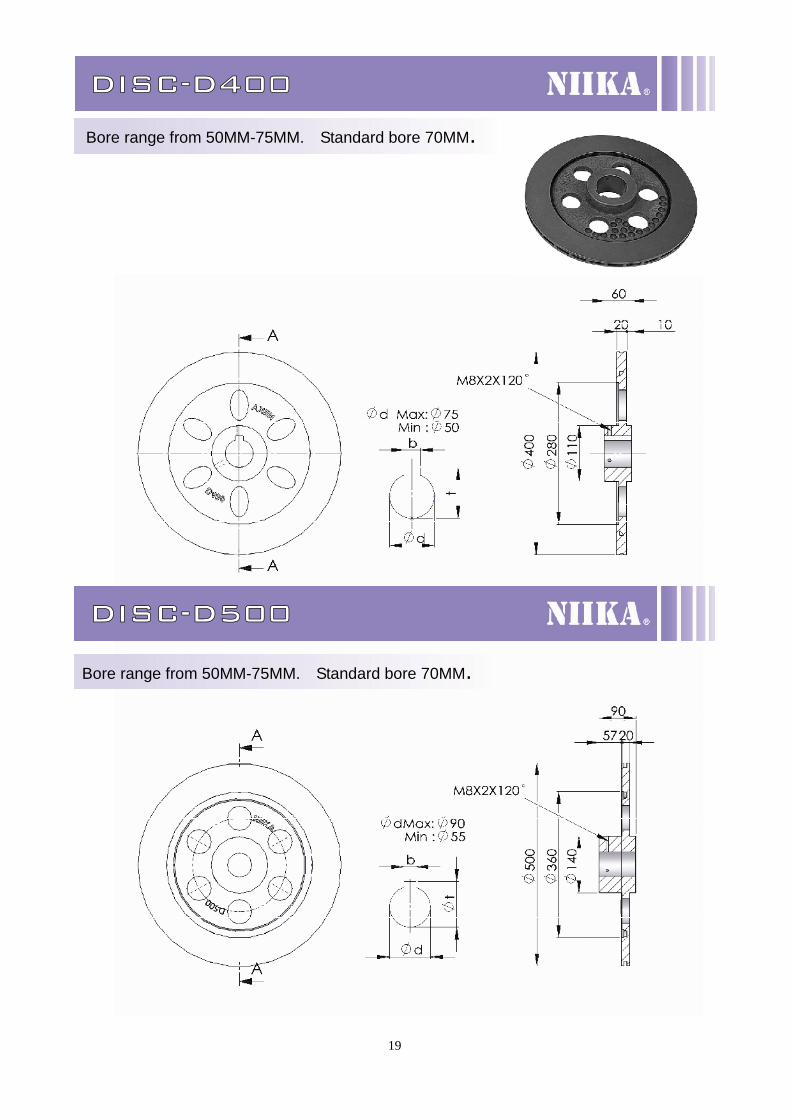
DISC-D400
Bore range from 50MM-75MM. Standard bore 70MM.
DISC-D500
Bore range from 50MM-75MM. Standard bore 70MM.
20
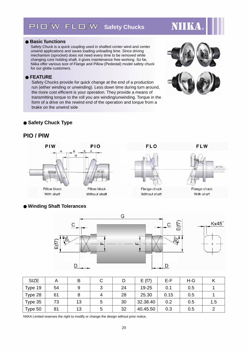
PIO/W FLO/W Safety Chucks
● Basic functionsSafety Chuck is a quick coupling used in shafted center wind and centerunwind applications and saves loading unloading time. Since drivingmechanism (sprocket) does not need every time to be removed whilechanging core holding shaft, it gives maintenance free working. So far,Niika offer various size of Flange and Pillow (Pedestal) model safety chuckfor our globe customers.
● FEATURESafety Chucks provide for quick change at the end of a productionrun (either winding or unwinding). Less down time during turn around,the more cost efficient is your operation. They provide a means oftransmitting torque to the roll you are winding/unwinding. Torque in theform of a drive on the rewind end of the operation and torque from abrake on the unwind side
● Safety Chuck Type
PIO / PIW
●Winding Shaft Tolerances
SIZE A B C D E (f7) E-F H-G KType 19 54 9 3 24 19-25 0.1 0.5 1Type 28 61 8 4 28 25.30 0.15 0.5 1Type 35 73 13 5 30 32.38.40 0.2 0.5 1.5Type 50 81 13 5 32 40.45.50 0.3 0.5 2
NIIKA Limited reserves the right to modify or change the design without prior notice.
21
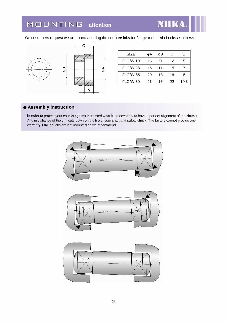
MOUNTING attention
On customers request we are manufacturing the countersinks for flange mounted chucks as follows:
● Assembly instruction
SIZE φA φB C D
FLO/W 19 15 9 12 5
FLO/W 28 18 11 15 7
FLO/W 35 20 13 16 8
FLO/W 50 26 18 22 10.5
In order to protect your chucks against increased wear it is necessary to have a perfect alignment of the chucks.Any misalliance of the unit cuts down on the life of your shaft and safety chuck. The factory cannot provide anywarranty if the chucks are not mounted as we recommend.
22
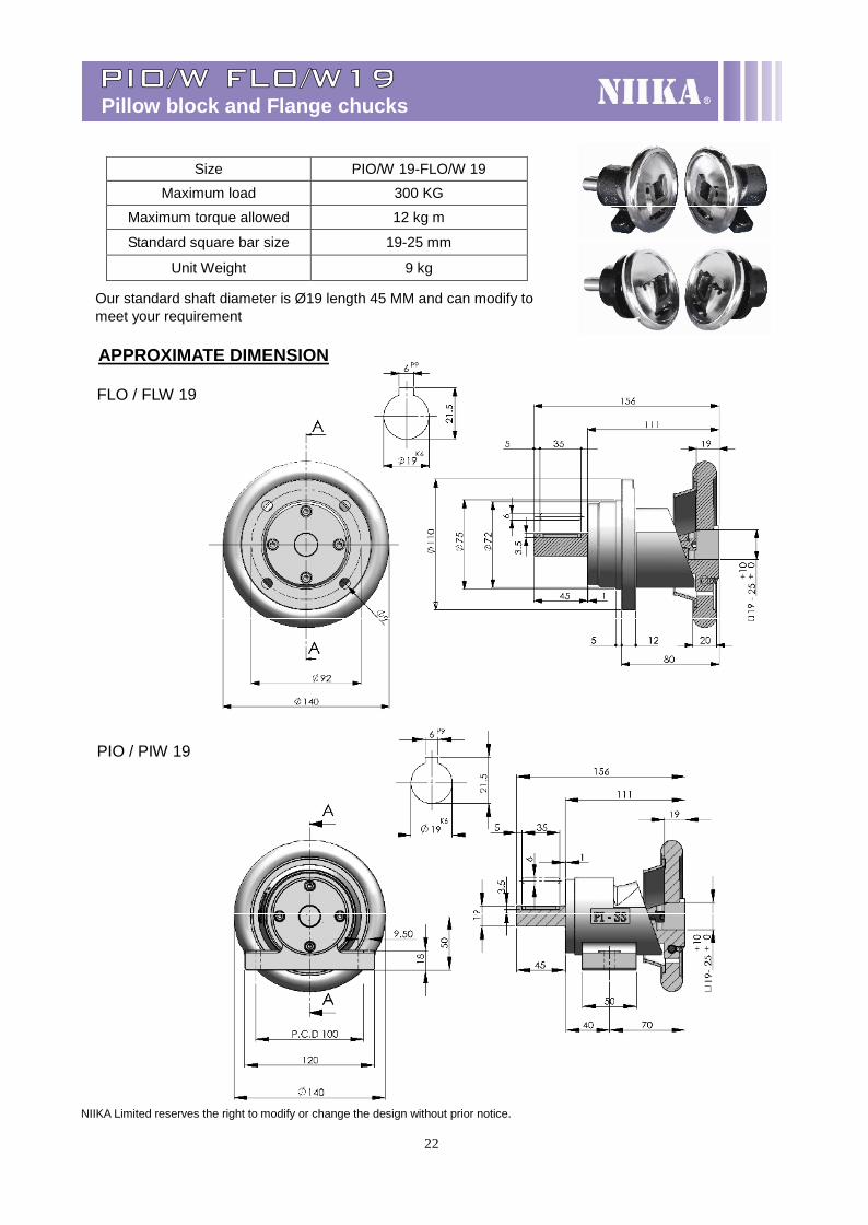
PIO/W FLO/W19Pillow block and Flange chucks
Our standard shaft diameter is Ø19 length 45 MM and can modify tomeet your requirement
APPROXIMATE DIMENSION
FLO / FLW 19
PIO / PIW 19
NIIKA Limited reserves the right to modify or change the design without prior notice.
Size PIO/W 19-FLO/W 19
Maximum load 300 KG
Maximum torque allowed 12 kg m
Standard square bar size 19-25 mm
Unit Weight 9 kg
23
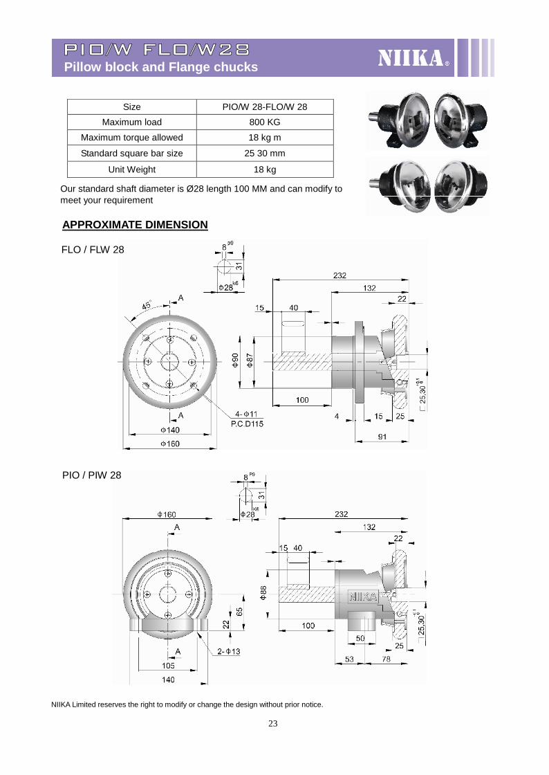
PIO/W FLO/W28Pillow block and Flange chucks
Our standard shaft diameter is Ø28 length 100 MM and can modify tomeet your requirement
APPROXIMATE DIMENSION
FLO / FLW 28
PIO / PIW 28
NIIKA Limited reserves the right to modify or change the design without prior notice.
Size PIO/W 28-FLO/W 28
Maximum load 800 KG
Maximum torque allowed 18 kg m
Standard square bar size 25 30 mm
Unit Weight 18 kg

24
PIO/W FLO/W35Pillow block and Flange chucks
Our standard shaft diameter is Ø35 length 70 MM and can modify tomeet your requirement
APPROXIMATE DIMENSION
FLO / FLW 35
PIO / PIW 35
NIIKA Limited reserves the right to modify or change the design without prior notice.
Size PIO/W 35-FLO/W 35
Maximum load 1600 KG
Maximum torque allowed 35 kg m
Standard square bar size 32 38 40 mm
Unit Weight 27 kg
25
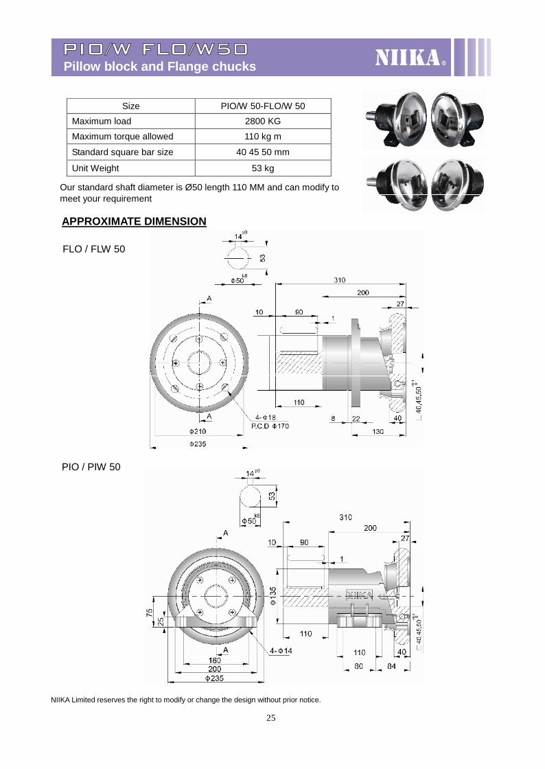
PIO/W FLO/W50Pillow block and Flange chucks
Our standard shaft diameter is Ø50 length 110 MM and can modify tomeet your requirement
APPROXIMATE DIMENSION
FLO / FLW 50
PIO / PIW 50
NIIKA Limited reserves the right to modify or change the design without prior notice.
Size PIO/W 50-FLO/W 50
Maximum load 2800 KG
Maximum torque allowed 110 kg m
Standard square bar size 40 45 50 mm
Unit Weight 53 kg
26
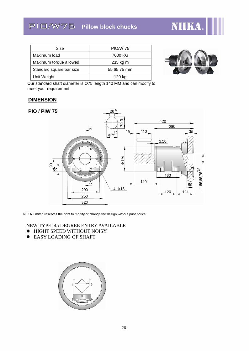
PIO/W75 Pillow block chucks
Our standard shaft diameter is Ø75 length 140 MM and can modify tomeet your requirement
DIMENSION
PIO / PIW 75
NIIKA Limited reserves the right to modify or change the design without prior notice.
Size PIO/W 75
Maximum load 7000 KG
Maximum torque allowed 235 kg m
Standard square bar size 55 65 75 mm
Unit Weight 120 kg
NEW TYPE: 45 DEGREE ENTRY AVAILABLE HIGHT SPEED WITHOUT NOISY EASY LOADING OF SHAFT
27
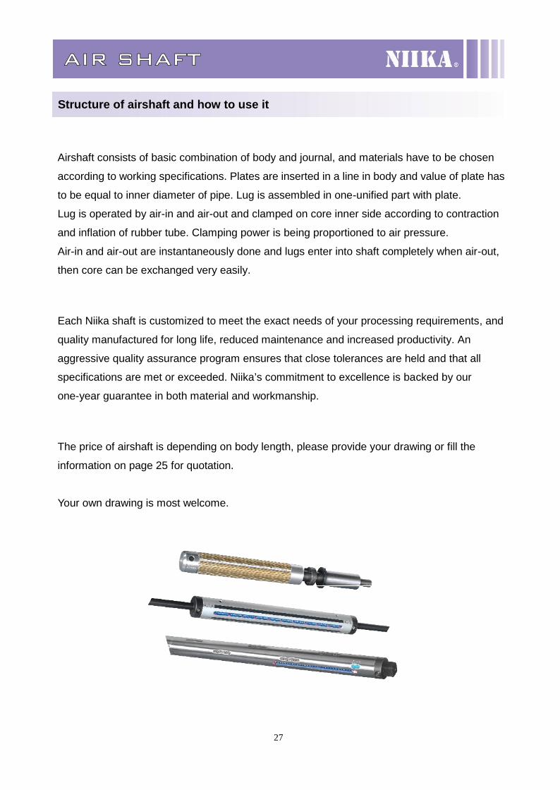
AIR SHAFT
Structure of airshaft and how to use it
Airshaft consists of basic combination of body and journal, and materials have to be chosen
according to working specifications. Plates are inserted in a line in body and value of plate has
to be equal to inner diameter of pipe. Lug is assembled in one-unified part with plate.
Lug is operated by air-in and air-out and clamped on core inner side according to contraction
and inflation of rubber tube. Clamping power is being proportioned to air pressure.
Air-in and air-out are instantaneously done and lugs enter into shaft completely when air-out,
then core can be exchanged very easily.
Each Niika shaft is customized to meet the exact needs of your processing requirements, and
quality manufactured for long life, reduced maintenance and increased productivity. An
aggressive quality assurance program ensures that close tolerances are held and that all
specifications are met or exceeded. Niika’s commitment to excellence is backed by our
one-year guarantee in both material and workmanship.
The price of airshaft is depending on body length, please provide your drawing or fill the
information on page 25 for quotation.
Your own drawing is most welcome.
28
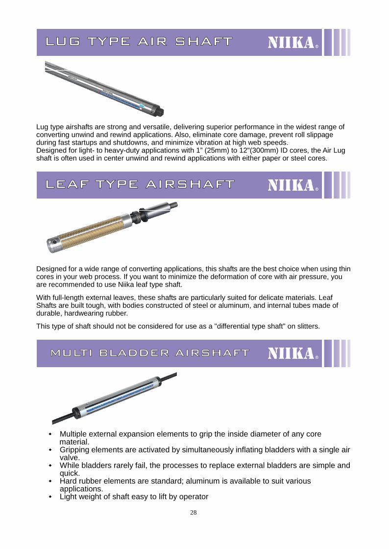
LUG TYPE AIR SHAFT
Lug type airshafts are strong and versatile, delivering superior performance in the widest range ofconverting unwind and rewind applications. Also, eliminate core damage, prevent roll slippageduring fast startups and shutdowns, and minimize vibration at high web speeds.Designed for light- to heavy-duty applications with 1” (25mm) to 12"(300mm) ID cores, the Air Lugshaft is often used in center unwind and rewind applications with either paper or steel cores.
LEAF TYPE AIRSHAFT
Designed for a wide range of converting applications, this shafts are the best choice when using thincores in your web process. If you want to minimize the deformation of core with air pressure, youare recommended to use Niika leaf type shaft.
With full-length external leaves, these shafts are particularly suited for delicate materials. LeafShafts are built tough, with bodies constructed of steel or aluminum, and internal tubes made ofdurable, hardwearing rubber.
This type of shaft should not be considered for use as a "differential type shaft" on slitters.
MULTI BLADDER AIRSHAFT
Multiple external expansion elements to grip the inside diameter of any corematerial.
Gripping elements are activated by simultaneously inflating bladders with a single airvalve.
While bladders rarely fail, the processes to replace external bladders are simple andquick.
Hard rubber elements are standard; aluminum is available to suit variousapplications.
Light weight of shaft easy to lift by operator
29
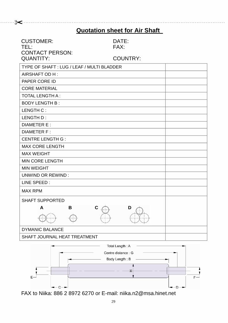
Quotation sheet for Air ShaftCUSTOMER: DATE:TEL: FAX:CONTACT PERSON:QUANTITY: COUNTRY:TYPE OF SHAFT : LUG / LEAF / MULTI BLADDER
AIRSHAFT OD H :
PAPER CORE ID
CORE MATERIAL
TOTAL LENGTH A :
BODY LENGTH B :
LENGTH C :
LENGTH D :
DIAMETER E :
DIAMETER F :
CENTRE LENGTH G :
MAX CORE LENGTH
MAX WEIGHT
MIN CORE LENGTH
MIN WEIGHT
UNWIND OR REWIND :
LINE SPEED :
MAX RPM
SHAFT SUPPORTED
DYMANIC BALANCE
SHAFT JOURNAL HEAT TREATMENT
FAX to Niika: 886 2 8972 6270 or E-mail: [email protected]
﹉﹉﹉﹉﹉﹉﹉﹉﹉﹉﹉﹉﹉﹉﹉﹉﹉﹉﹉﹉﹉﹉﹉﹉﹉﹉﹉﹉﹉﹉﹉﹉﹉﹉﹉﹉﹉﹉﹉﹉﹉﹉
﹉
A B C D
30
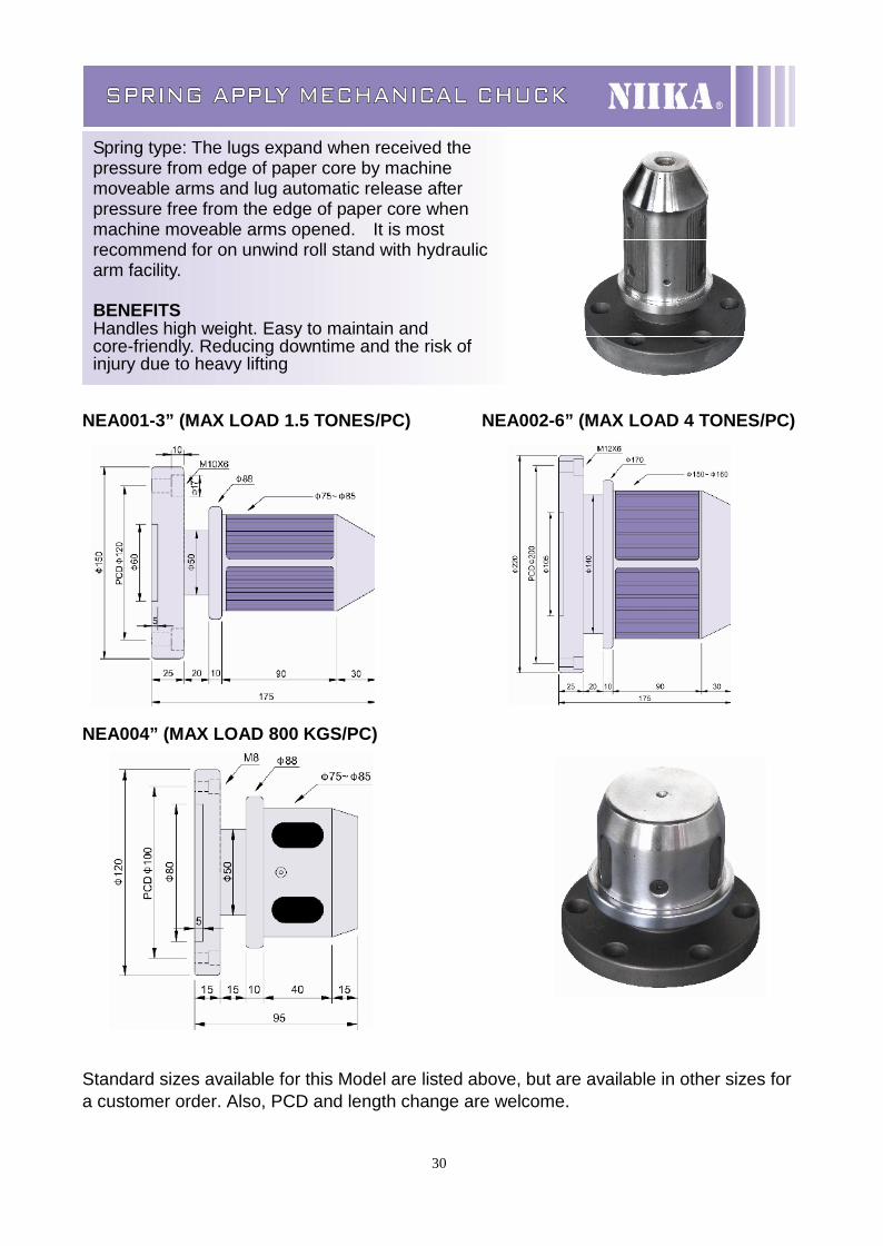
SPRING APPLY MECHANICAL CHUCK
NEA001-3” (MAX LOAD 1.5 TONES/PC) NEA002-6” (MAX LOAD 4 TONES/PC)
NEA004” (MAX LOAD 800 KGS/PC)
Standard sizes available for this Model are listed above, but are available in other sizes fora customer order. Also, PCD and length change are welcome.
Spring type: The lugs expand when received thepressure from edge of paper core by machinemoveable arms and lug automatic release afterpressure free from the edge of paper core whenmachine moveable arms opened. It is mostrecommend for on unwind roll stand with hydraulicarm facility.
BENEFITSHandles high weight. Easy to maintain andcore-friendly. Reducing downtime and the risk ofinjury due to heavy lifting
31
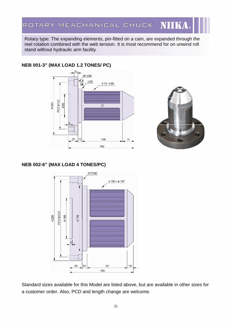
ROTARY MEACHANICAL CHUCK
NEB 001-3” (MAX LOAD 1.2 TONES/ PC)
NEB 002-6” (MAX LOAD 4 TONES/PC)
Standard sizes available for this Model are listed above, but are available in other sizes fora customer order. Also, PCD and length change are welcome.
Rotary type: The expanding elements, pin-fitted on a cam, are expanded through thereel rotation combined with the web tension. It is most recommend for on unwind rollstand without hydraulic arm facility.
32
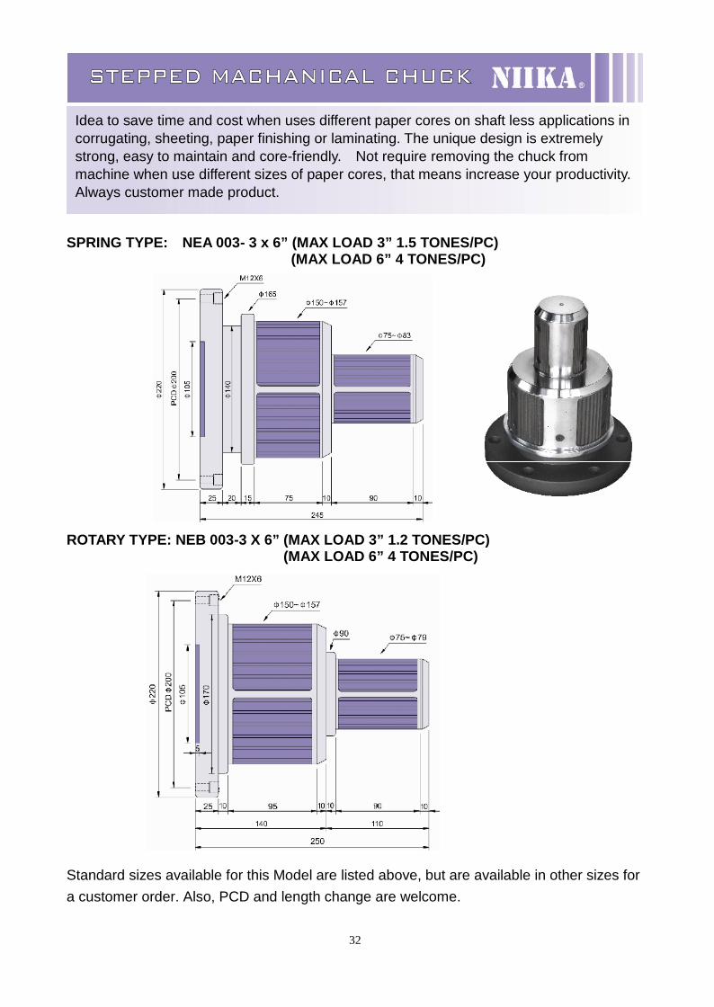
STEPPED MACHANICAL CHUCK
SPRING TYPE: NEA 003- 3 x 6” (MAX LOAD 3” 1.5 TONES/PC)(MAX LOAD 6” 4 TONES/PC)
ROTARY TYPE: NEB 003-3 X 6” (MAX LOAD 3” 1.2 TONES/PC)(MAX LOAD 6” 4 TONES/PC)
Standard sizes available for this Model are listed above, but are available in other sizes fora customer order. Also, PCD and length change are welcome.
Idea to save time and cost when uses different paper cores on shaft less applications incorrugating, sheeting, paper finishing or laminating. The unique design is extremelystrong, easy to maintain and core-friendly. Not require removing the chuck frommachine when use different sizes of paper cores, that means increase your productivity.Always customer made product.
33
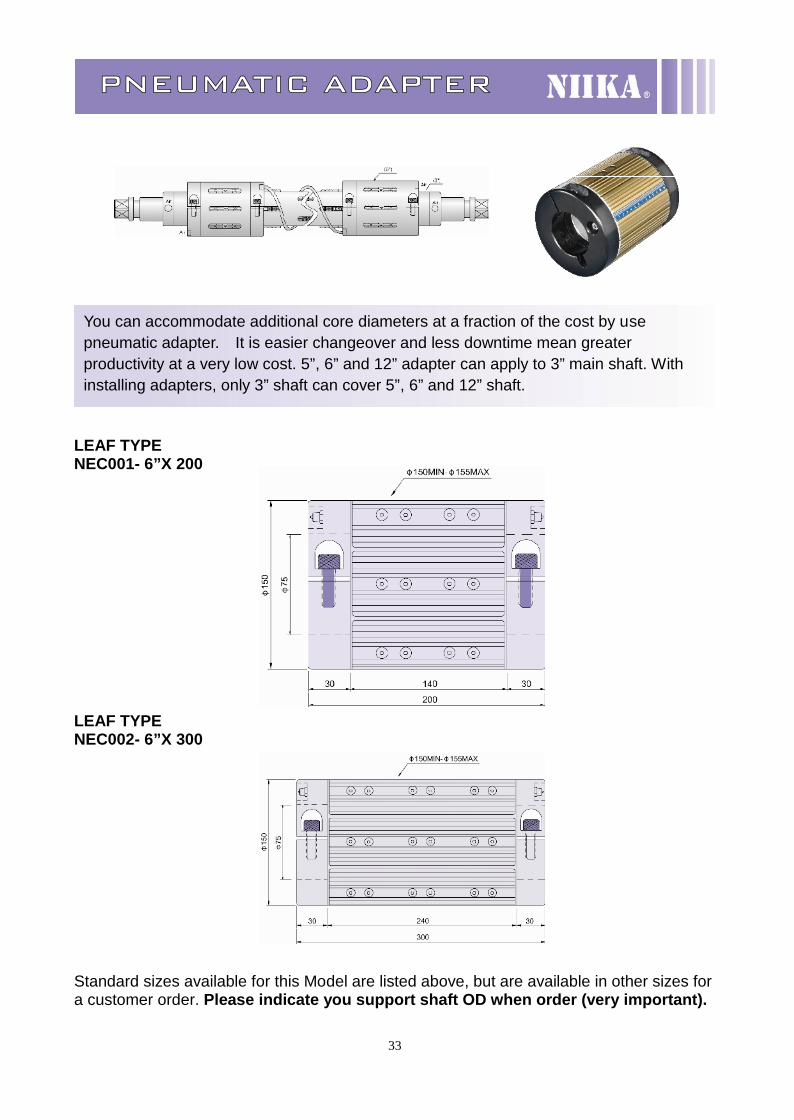
PNEUMATIC ADAPTER
LEAF TYPENEC001- 6”X 200
LEAF TYPENEC002- 6”X 300
Standard sizes available for this Model are listed above, but are available in other sizes fora customer order. Please indicate you support shaft OD when order (very important).
You can accommodate additional core diameters at a fraction of the cost by usepneumatic adapter. It is easier changeover and less downtime mean greaterproductivity at a very low cost. 5”, 6” and 12” adapter can apply to 3” main shaft. Withinstalling adapters, only 3” shaft can cover 5”, 6” and 12” shaft.
34
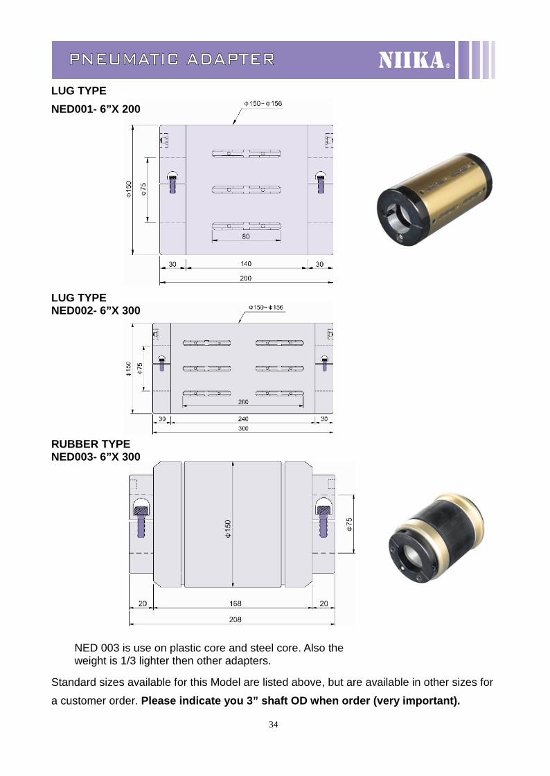
PNEUMATIC ADAPTER
LUG TYPENED001- 6”X 200
LUG TYPENED002- 6”X 300
RUBBER TYPENED003- 6”X 300
Standard sizes available for this Model are listed above, but are available in other sizes for
a customer order. Please indicate you 3” shaft OD when order (very important).
NED 003 is use on plastic core and steel core. Also theweight is 1/3 lighter then other adapters.
35
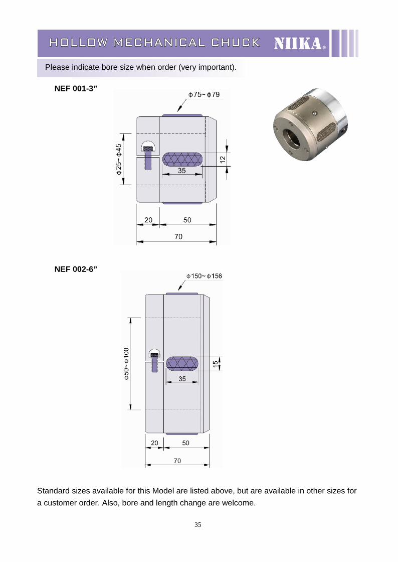
HOLLOW MECHANICAL CHUCK
Please indicate bore size when order (very important).
NEF 001-3”
NEF 002-6”
Standard sizes available for this Model are listed above, but are available in other sizes fora customer order. Also, bore and length change are welcome.
36
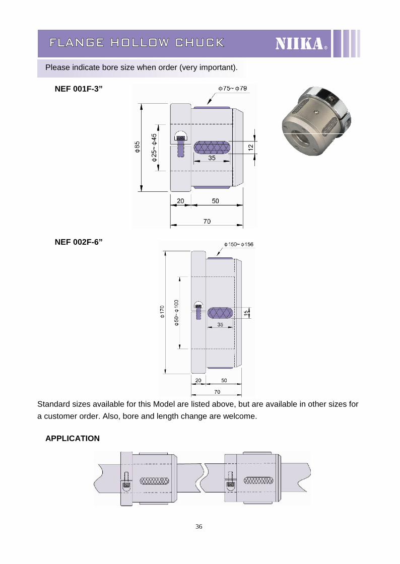
FLANGE HOLLOW CHUCK
Please indicate bore size when order (very important).
NEF 001F-3”
NEF 002F-6”
Standard sizes available for this Model are listed above, but are available in other sizes fora customer order. Also, bore and length change are welcome.
APPLICATION
37
AIR DIFFERENTIAL SHAFT
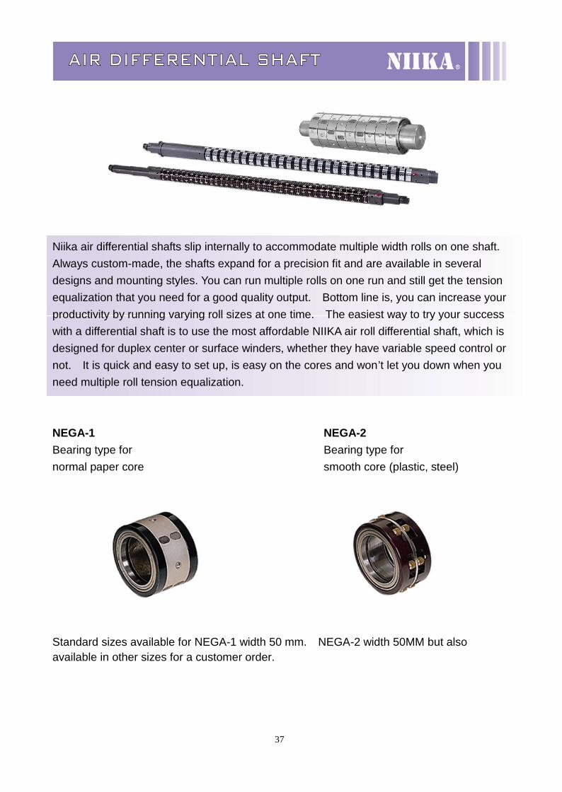
Niika air differential shafts slip internally to accommodate multiple width rolls on one shaft.Always custom-made, the shafts expand for a precision fit and are available in severaldesigns and mounting styles. You can run multiple rolls on one run and still get the tensionequalization that you need for a good quality output. Bottom line is, you can increase yourproductivity by running varying roll sizes at one time. The easiest way to try your successwith a differential shaft is to use the most affordable NIIKA air roll differential shaft, which isdesigned for duplex center or surface winders, whether they have variable speed control ornot. It is quick and easy to set up, is easy on the cores and won’t let you down when youneed multiple roll tension equalization.
NEGA-1 NEGA-2Bearing type for Bearing type fornormal paper core smooth core (plastic, steel)
Standard sizes available for NEGA-1 width 50 mm. NEGA-2 width 50MM but alsoavailable in other sizes for a customer order.
38
MECHANICAL DIFFERENTIAL SHAFT
NEG 001- 37 MM
NEG 002-50MM
Standard sizes available for this Model are as NEG001-37 MM and NEG002-50 MM listedabove, but is available in other sizes for a custom order.APPLICATION:
Rotating material of sleeve bore core and frictionalmaterial for two sides all adopt Bakelite. The frictionalstrength is subject to either spring pressure or cylinderpower to decide each torque assembly of slippage, foreasy to control the tension adjustment in each material.1. Sizes of inside diameter can make by suitable shaft.2. Other lengths are available on request.
39
Powder Brake POB 006~400 series
SpecificationFix torquekgfm(Nm)
Capability(75°C)
Compelling air-coolingconcessional slide rate of work
Type
Electric(A)
ElectricPower
(W)(S)
Inertial torque(kgm2)
Airpressure
(pa)
Air volume(m3/min)
Ratio(W)
Weight(kg)
Max. speed ofRotation(r/min)
Weight ofMagnetic
Powder (g)
POB-006 0.6(6) 0.81 19.4 0.09 6.10*0-5 1.8*104 0.1 170 5.2 1800 10
POB-012 1.2(12) 0.94 22.5 0.10 1.34*10-3 3*104 0.2 250 5.2 1,800 20
POB-025 2.5(25) 1.24 30 0.12 3.80*10-3 5*104 0.4 380 9 1,800 33
POB-050 5(50) 2.15 51.5 0.13 9.50*10-3 1*105 0.6 700 15.5 1,800 60
POB-100 10(100) 2.40 57.6 0.25 3.50*10-2 6*104 1.1 1,100 34 1,800 140POB-200 20(200) 2.70 64.8 0.12 9.15*10-2 5*104 1.6 1,900 53 1,800 225
POB-400 40(400) 5 120 0.40 2.43*10-1 1.6*105 2.0 2,100 102 1,800 300Size of appearance (mm)
SpecificationR Axis bodyType L1 L2 L3 L4 L5 D1 D2 D3 D4(G7) Q
Pathway Depth D(h7) W(p7) T(0-0.2)POB-006 114 57 26 14 46 134 *** 64 42 1/8 M4 10 12 4 13.5POB-012 132 83 29 15 49 152 126 64 42 1/8 M4 8 15 5 17POB-025 155 91 43 17 64 184 160 78 55 1/8 M5 10 20 5 22POB-050 193 102 55 30 91 219 196 100 74 1/4 M6 12 25 7 28
POB-100 239 139 65 28 100 278 160 140 100 3/8 M10 20 30 7 33
POB-200 278 169 69 30 109 327 174 150 110 3/8 M10 20 35 10 38.5
POB-400 339 200 92 35 139 398 230 200 130 3/8 M10 20 45 12 48.5We reserve the right of changing specification or size to our products
40
Powder Clutch POC 006~400 series
SpecificationType Fix torque
kgfm(Nm)Capability
(75°C)Inertial torque
(kgm2)Compelling air-cooling
concessional slide rate of work
Electric(A)
ElectricPower
(W)(S) INPUT OUTPUT
Airpressure
(pa)
Air volume(m3/min)
Ratio(W)
Weight(kg)
Max. speed ofRotation(r/min)
Weight ofMagnetic
Powder (g)
POC-006 0.6(6) 0.81 19.4 0.09 6.00*10-4 1.93*10-4 1.8*104 0.1 170 5.2 1800 10
POC-012 1.2(12) 0.94 22.5 0.10 1.34*10-3 4.90*10-4 3*104 0.2 250 6 1,800 20
POC-025 2.5(25) 1.24 30 0.12 3.80*10-3 1.49*10-3 5*104 0.4 380 11 1,800 33
POC-050 5(50) 2.15 51.5 0.13 9.50*10-3 4.80*10-3 1*105 0.6 700 18.5 1,800 60
POC-100 10(100) 2.40 57.6 0.25 3.50*10-2 2.50*10-2 6*104 1.1 1,100 37 1,800 140
POC-200 20(200) 2.70 64.8 0.37 9.15*10-2 6.89*10-2 5*104 1.6 1,900 59 1,800 225
POC-400 40(400) 5 120 0.40 2.43*10-1 1.50*10-1 1.6*105 2.0 2,100 110 1,800 300Size of appearance (mm)
SpecificationR Axis bodyType L1 L2 L3 L4 L5 D1 D2 D3 D4(G7) Q
Pathway Depth D(h7) W(p7) T(0-0.2)POC-006 164 72 26 14 46 134 *** 64 42 1/8 M4 10 12 4 13.5POC-012 192 94 29 15 49 152 126 64 42 1/8 M4 8 15 5 17POC-025 230 102 43 17 64 184 160 78 55 1/8 M5 10 20 5 22POC-050 294 112 55 30 91 219 196 100 74 1/4 M6 12 25 7 28
POC-100 360 160 65 28 100 278 160 140 100 3/8 M10 20 30 7 33
POC-200 408 190 69 30 109 327 174 150 110 3/8 M10 20 35 10 38.5
POC-400 500 221 92 35 139 398 230 200 130 3/8 M10 20 45 12 48.5We reserve the right of changing specification or size to our products
41
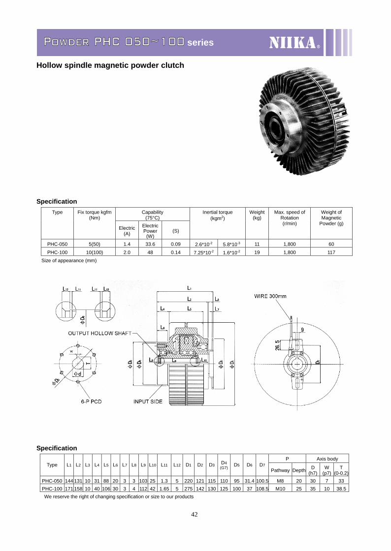
Powder PHB 050~100 series
Hollow spindle magnetic powder brake
SpecificationCapability
(75°C)Type Fix torque kgfm
(Nm)
Electric(A)
ElectricPower
(W)(S)
Inertial torque(kgm2)
Weight(kg)
Max. speed ofRotation(r/min)
Weight ofMagnetic
Powder (g)
PHB-050 5(50) 0.94 22.6 0.17 2.3*10-2 11 1,800 60
PHB-100 10(100) 1.21 28.8 0.30 9.75*10-2 21.5 1,800 117Size of appearance (mm)
SpecificationP Axis bodyType L1 L2 L3 L4 L5 L6 L7 D1 D2 D3 D4
(G7) D5Pathway Depth d(h7) W(p7) T(0-0.2)
PHB-050 120 88 27 5 115 1.3 5 220 172 150 110 31.4 M10 19 30 7 33PHB-100 140 106 29 5 130 1.65 5 275 190 150 110 37 M10 22 35 10 38.5We reserve the right of changing specification or size to our products
42
Powder PHC 050~100 series
Hollow spindle magnetic powder clutch
SpecificationCapability
(75°C)Type Fix torque kgfm
(Nm)
Electric(A)
ElectricPower
(W)(S)
Inertial torque(kgm2)
Weight(kg)
Max. speed ofRotation(r/min)
Weight ofMagnetic
Powder (g)
PHC-050 5(50) 1.4 33.6 0.09 2.6*10-2 5.8*10-3 11 1,800 60
PHC-100 10(100) 2.0 48 0.14 7.25*10-2 1.6*10-2 19 1,800 117Size of appearance (mm)
SpecificationP Axis body
Type L1 L2 L3 L4 L5 L6 L7 L8 L9 L10 L11 L12 D1 D2 D3 D4(G7) D5 D6 D7
Pathway Depth D(h7)
W(p7)
T(0-0.2)
PHC-050 144 131 10 31 88 20 3 3 103 25 1.3 5 220 121 115 110 95 31.4 100.5 M8 20 30 7 33PHC-100 171 158 10 40 106 30 3 4 112 42 1.65 5 275 142 130 125 100 37 108.5 M10 25 35 10 38.5We reserve the right of changing specification or size to our products
43
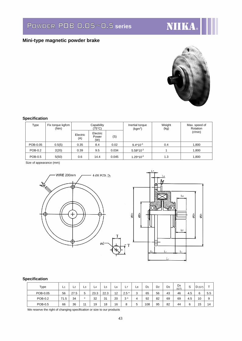
Powder POB 0.05~0.5 series
Mini-type magnetic powder brake
SpecificationCapability
(75°C)Type Fix torque kgfcm
(Nm)
Electric(A)
ElectricPower
(W)(S)
Inertial torque(kgm2)
Weight(kg)
Max. speed ofRotation(r/min)
POB-0.05 0.5(5) 0.35 8.4 0.02 9.4*10-3 0.4 1,800
POB-0.2 2(20) 0.39 9.5 0.034 5.58*10-3 1 1,800
POB-0.5 5(50) 0.6 14.4 0.045 1.25*10-3 1.3 1,800
Size of appearance (mm)
Specification
Type L1 L2 L3 L4 L5 L6 L7 L8 D1 D2 D3 D4(G7) S D (G7) T
POB-0.05 56 27.5 5 23.3 22.3 12 2.5 * 3 65 56 43 46 4.5 6 5.5
POB-0.2 71.5 34 * 32 31 20 3 * 4 92 82 69 69 4.5 10 9
POB-0.5 66 36 11 19 18 16 8 5 108 95 82 44 6 15 14
We reserve the right of changing specification or size to our products
44
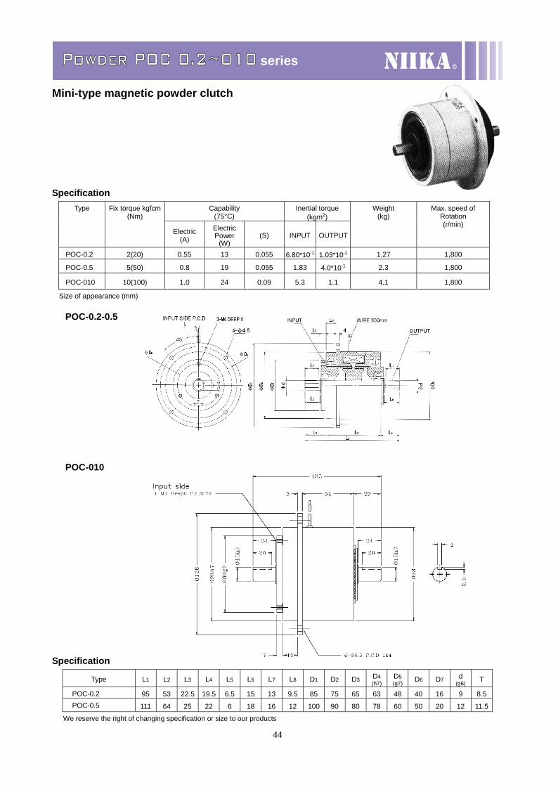
Powder POC 0.2~010 series
Mini-type magnetic powder clutch
SpecificationCapability
(75°C)Inertial torque
(kgm2)Type Fix torque kgfcm
(Nm)
Electric(A)
ElectricPower
(W)(S) INPUT OUTPUT
Weight(kg)
Max. speed ofRotation(r/min)
POC-0.2 2(20) 0.55 13 0.055 6.80*10-1 1.03*10-1 1.27 1,800
POC-0.5 5(50) 0.8 19 0.055 1.83 4.0*10-1 2.3 1,800
POC-010 10(100) 1.0 24 0.09 5.3 1.1 4.1 1,800
Size of appearance (mm)
POC-0.2-0.5
POC-010
Specification
Type L1 L2 L3 L4 L5 L6 L7 L8 D1 D2 D3 D4(h7)
D5(g7) D6 D7 d
(g6) T
POC-0.2 95 53 22.5 19.5 6.5 15 13 9.5 85 75 65 63 48 40 16 9 8.5POC-0.5 111 64 25 22 6 18 16 12 100 90 80 78 60 50 20 12 11.5
We reserve the right of changing specification or size to our products
45
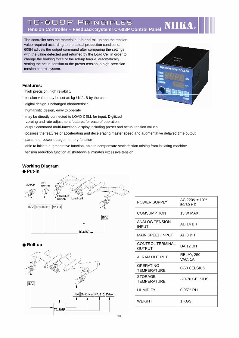
TC-608P PrinciplesTension Controller – Feedback SystemTC-608P Control Panel
The controller sets the material put-in and roll-up and the tension value required according to the actual production conditions. 608H adjusts the output command after comparing the settings with the value detected and returned by the Load Cell in order to change the braking force or the roll-up torque, automaticallysetting the actual tension to the preset tension, a high-precision
tension control system.
Features:˙ high precision, high reliability
˙ tension value may be set at: kg / N / LB by the user
˙ digital design, unchanged characteristic
˙ humanistic design, easy to operate
˙ may be directly connected to LOAD CELL for input; Digitizedzeroing and rate adjustment features for ease of operation.
˙ output command multi-functional display including preset and actual tension values
˙ possess the features of accelerating and decelerating master speed and augmentative delayed time output
˙ parameter power outage memory function
˙ able to initiate augmentative function, able to compensate static friction arising from initiating machine
˙ tension reduction function at shutdown eliminates excessive tension
Working Diagram● Put-in
● Roll-up
POWER SUPPLY AC 220V ± 10%50/60 HZ
COMSUMPTION 15 W MAX.
ANALOG TENSIONINPUT AD 14 BIT
MAIN SPEED INPUT AD 8 BIT
CONTROL TERMINALOUTPUT DA 12 BIT
ALRAM OUT PUT RELAY, 250VAC, 1A
OPERATINGTEMPERATURE 0-60 CELSIUS
STORAGETEMPERATURE -20-70 CELSIUS
HUMIDIFY 0-95% RH
WEIGHT 1 KGS
46
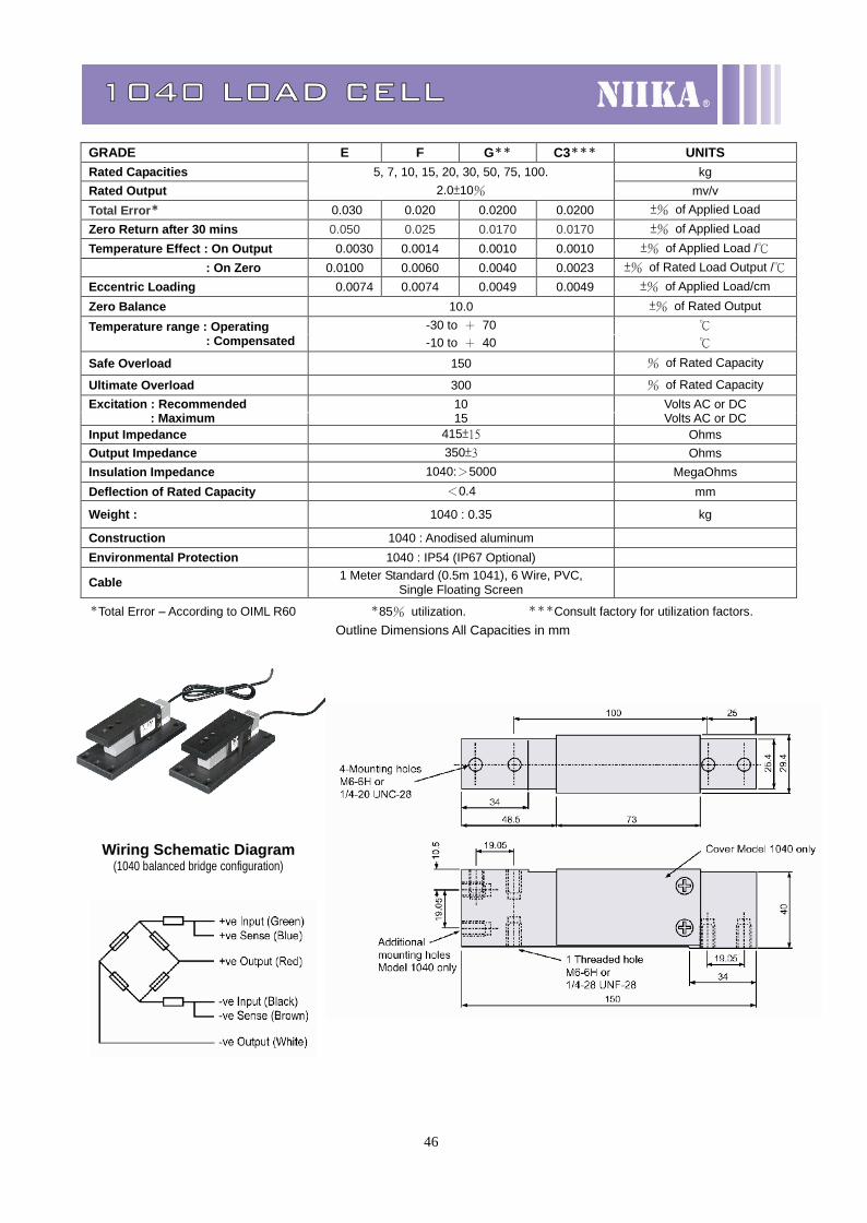
1040 LOAD CELL
*Total Error – According to OIML R60 *85% utilization. ***Consult factory for utilization factors. Outline Dimensions All Capacities in mm
GRADE E F G** C3*** UNITSRated Capacities 5, 7, 10, 15, 20, 30, 50, 75, 100. kgRated Output 2.0±10% mv/vTotal Error* 0.030 0.020 0.0200 0.0200 ±% of Applied LoadZero Return after 30 mins 0.050 0.025 0.0170 0.0170 ±% of Applied LoadTemperature Effect : On Output 0.0030 0.0014 0.0010 0.0010 ±% of Applied Load /℃ : On Zero 0.0100 0.0060 0.0040 0.0023 ±% of Rated Load Output /℃Eccentric Loading 0.0074 0.0074 0.0049 0.0049 ±% of Applied Load/cmZero Balance 10.0 ±% of Rated Output
-30 to + 70 ℃Temperature range : Operating : Compensated -10 to + 40 ℃
Safe Overload 150 % of Rated Capacity
Ultimate Overload 300 % of Rated CapacityExcitation : Recommended 10 Volts AC or DC : Maximum 15 Volts AC or DCInput Impedance 415±15 OhmsOutput Impedance 350±3 OhmsInsulation Impedance 1040:>5000 MegaOhmsDeflection of Rated Capacity <0.4 mm
Weight : 1040 : 0.35 kg
Construction 1040 : Anodised aluminumEnvironmental Protection 1040 : IP54 (IP67 Optional)
Cable 1 Meter Standard (0.5m 1041), 6 Wire, PVC,Single Floating Screen
Wiring Schematic Diagram(1040 balanced bridge configuration)
47
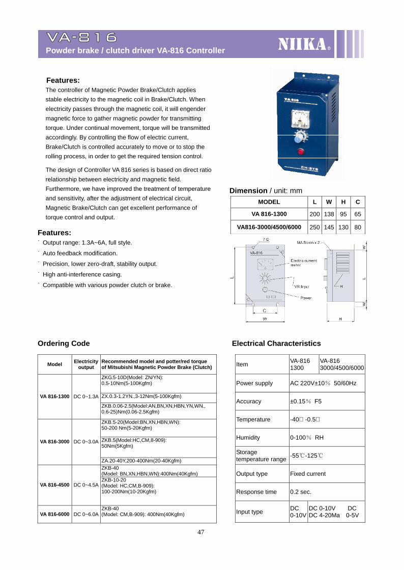
VA-816Powder brake / clutch driver VA-816 Controller
Features:˙ Output range: 1.3A~6A, full style.
˙ Auto feedback modification.
˙ Precision, lower zero-draft, stability output.
˙ High anti-interference casing.
˙ Compatible with various powder clutch or brake.
Ordering Code Electrical Characteristics
Model Electricityoutput
Recommended model and potter/red torqueof Mitsubishi Magnetic Powder Brake (Clutch)
ZKG.5-10D(Model: ZN/YN):0.5-10Nm(5-100Kgfm)
ZX.0.3-1.2YN.,3-12Nm(5-100Kgfm)VA 816-1300 DC 0~1.3A
ZKB.0.06-2.5(Model:AN,BN,XN,HBN,YN,WN.,0.6-25)Nm(0.06-2.5Kgfm)
ZKB.5-20(Model:BN,XN,HBN,WN):50-200 Nm(5-20Kgfm)
ZKB.5(Model:HC,CM,8-909):50Nm(5Kgfm)
VA 816-3000 DC 0~3.0A
ZA.20-40Y,200-400Nm(20-40Kgfm)ZKB-40(Model: BN,XN,HBN,WN):400Nm(40Kgfm)
VA 816-4500 DC 0~4.5AZKB-10-20(Model: HC,CM,B-909):100-200Nm(10-20Kgfm)
VA 816-6000 DC 0~6.0AZKB-40(Model: CM,B-909): 400Nm(40Kgfm)
MODEL L W H C
VA 816-1300 200 138 95 65
VA816-3000/4500/6000 250 145 130 80
Item VA-8161300
VA-8163000/4500/6000
Power supply AC 220V±10% 50/60Hz
Accuracy ±0.15% F5
Temperature -40℃ -0.5℃
Humidity 0-100% RH
Storagetemperature range -55℃-125℃
Output type Fixed current
Response time 0.2 sec.
Input type DC0-10V
DC 0-10V DCDC 4-20Ma 0-5V
Features:The controller of Magnetic Powder Brake/Clutch appliesstable electricity to the magnetic coil in Brake/Clutch. Whenelectricity passes through the magnetic coil, it will engendermagnetic force to gather magnetic powder for transmittingtorque. Under continual movement, torque will be transmittedaccordingly. By controlling the flow of electric current,Brake/Clutch is controlled accurately to move or to stop therolling process, in order to get the required tension control.
The design of Controller VA 816 series is based on direct ratiorelationship between electricity and magnetic field.Furthermore, we have improved the treatment of temperatureand sensitivity, after the adjustment of electrical circuit,Magnetic Brake/Clutch can get excellent performance oftorque control and output.
Dimension / unit: mm

47
48
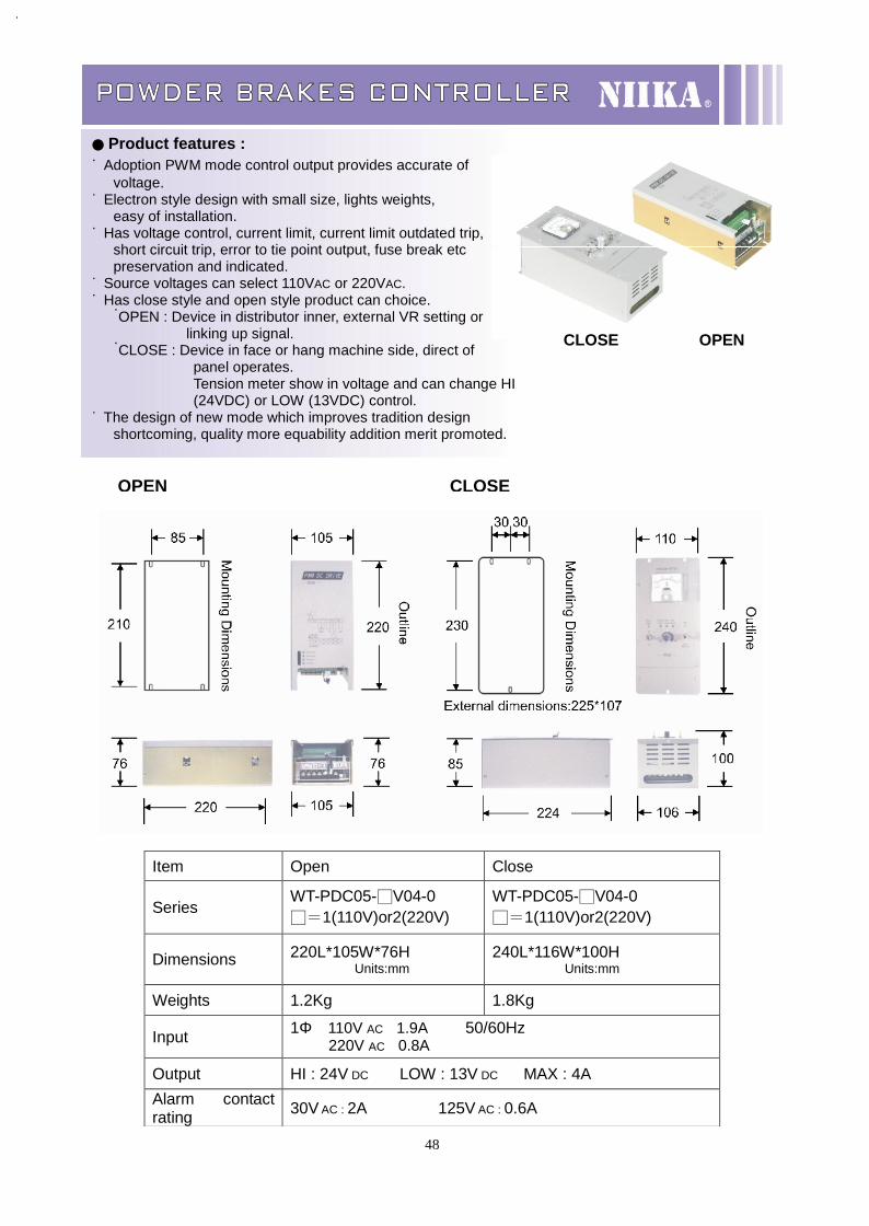
OPEN
POWDER BRAKES CONTROLLER
Item Open Close
SeriesWT-PDC05-□V04-0□=1(110V)or2(220V)
WT-PDC05-□V04-0□=1(110V)or2(220V)
Dimensions 220L*105W*76HUnits:mm
240L*116W*100HUnits:mm
Weights 1.2Kg 1.8Kg
Input 1Φ 110V AC 1.9A 50/60Hz220V AC 0.8A
Output HI : 24V DC LOW : 13V DC MAX : 4AAlarm contactrating 30V AC : 2A 125V AC : 0.6A
● Product features :˙ Adoption PWM mode control output provides accurate of
voltage.˙ Electron style design with small size, lights weights,
easy of installation.˙ Has voltage control, current limit, current limit outdated trip,
short circuit trip, error to tie point output, fuse break etcpreservation and indicated.
˙ Source voltages can select 110VAC or 220VAC.˙ Has close style and open style product can choice.˙OPEN : Device in distributor inner, external VR setting or
linking up signal.˙CLOSE : Device in face or hang machine side, direct of
panel operates.Tension meter show in voltage and can change HI(24VDC) or LOW (13VDC) control.
˙ The design of new mode which improves tradition designshortcoming, quality more equability addition merit promoted.
CLOSE OPEN
CLOSE
49
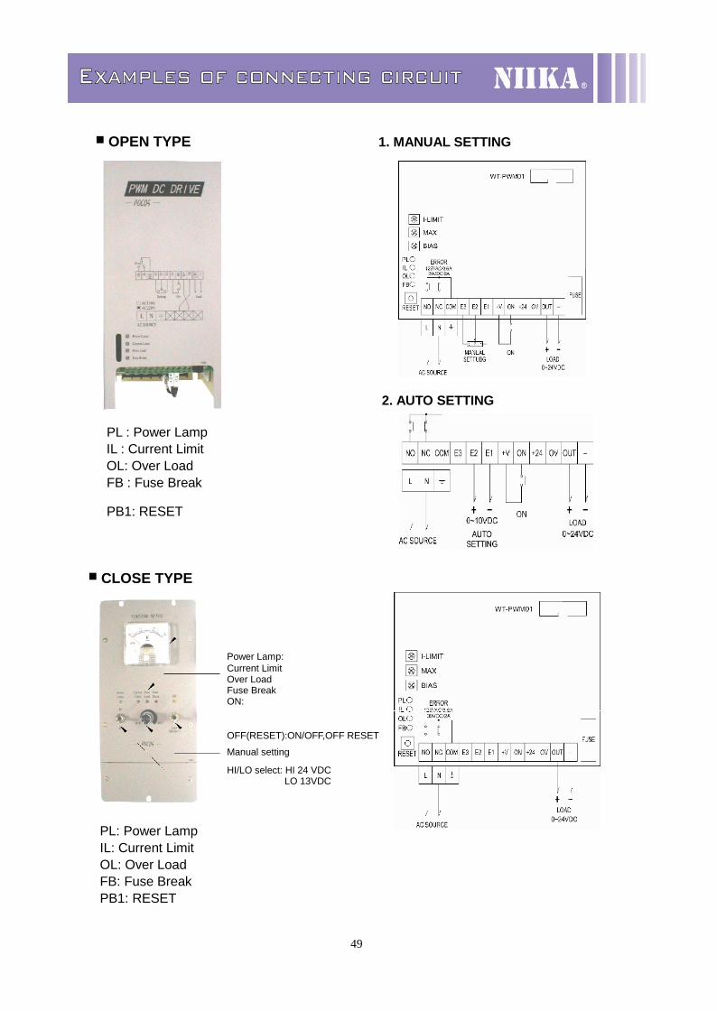
Examples of connecting circuit
■ OPEN TYPE 1. MANUAL SETTING
2. AUTO SETTING
PL : Power Lamp IL : Current LimitOL: Over LoadFB : Fuse Break
PB1: RESET
■ CLOSE TYPE
PL: Power LampIL: Current LimitOL: Over LoadFB: Fuse BreakPB1: RESET
Power Lamp:Current LimitOver LoadFuse BreakON:
OFF(RESET):ON/OFF,OFF RESET
Manual setting
HI/LO select: HI 24 VDC LO 13VDC
50
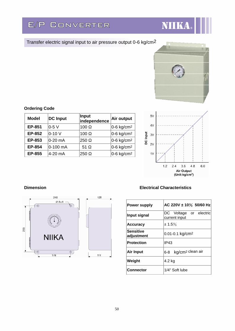
E/P Converter
Transfer electric signal input to air pressure output 0-6 kg/cm2
Ordering Code
Dimension Electrical Characteristics
Model DC Input Inputindependence Air output
EP-851 0-5 V 100 Ω 0-6 kg/cm2
EP-852 0-10 V 100 Ω 0-6 kg/cm2
EP-853 0-20 mA 250 Ω 0-6 kg/cm2
EP-854 0-100 mA 51 Ω 0-6 kg/cm2
EP-855 4-20 mA 250 Ω 0-6 kg/cm2
Power supply AC 220V ± 10% 50/60 Hz
Input signal DC Voltage or electriccurrent input
Accuracy ± 1.5%
Sensitiveadjustment 0.01-0.1 kg/cm2
Protection IP43
Air Input 6-8 kg/cm2 clean air
Weight 4.2 kg
Connector 1/4” Soft lube
51
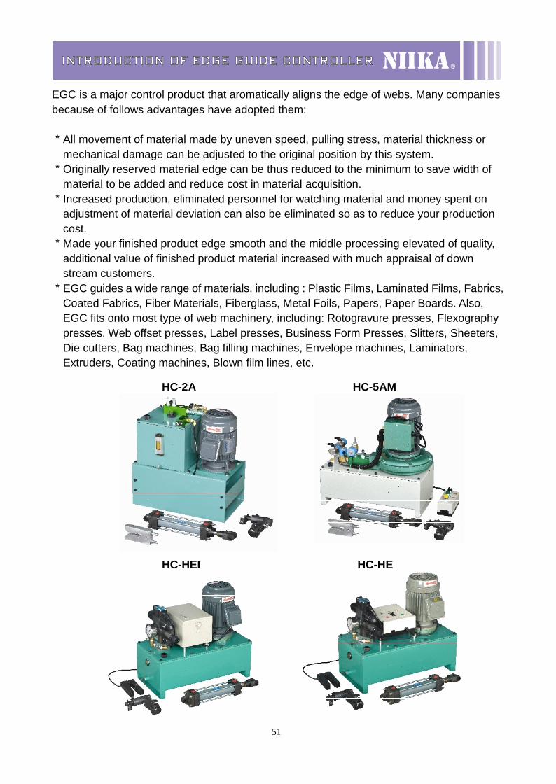
INTRODUCTION OF EDGE GUIDE CONTROLLER
EGC is a major control product that aromatically aligns the edge of webs. Many companiesbecause of follows advantages have adopted them:
*All movement of material made by uneven speed, pulling stress, material thickness ormechanical damage can be adjusted to the original position by this system.
*Originally reserved material edge can be thus reduced to the minimum to save width ofmaterial to be added and reduce cost in material acquisition.
*Increased production, eliminated personnel for watching material and money spent onadjustment of material deviation can also be eliminated so as to reduce your productioncost.
*Made your finished product edge smooth and the middle processing elevated of quality,additional value of finished product material increased with much appraisal of downstream customers.
*EGC guides a wide range of materials, including : Plastic Films, Laminated Films, Fabrics,Coated Fabrics, Fiber Materials, Fiberglass, Metal Foils, Papers, Paper Boards. Also,EGC fits onto most type of web machinery, including: Rotogravure presses, Flexographypresses. Web offset presses, Label presses, Business Form Presses, Slitters, Sheeters,Die cutters, Bag machines, Bag filling machines, Envelope machines, Laminators,Extruders, Coating machines, Blown film lines, etc.
HC-2A HC-5AM
HC-HEI HC-HE
52
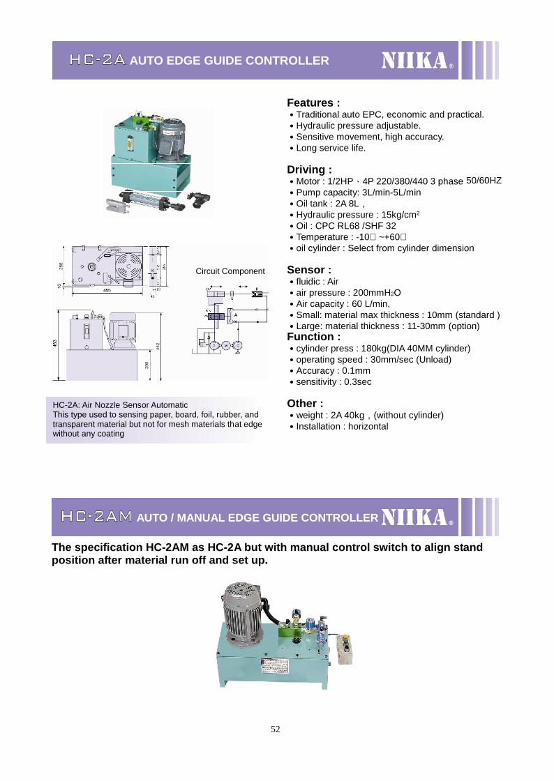
HC-2A AUTO EDGE GUIDE CONTROLLER
HC-2AM AUTO / MANUAL EDGE GUIDE CONTROLLER
The specification HC-2AM as HC-2A but with manual control switch to align standposition after material run off and set up.
HC-2A: Air Nozzle Sensor AutomaticThis type used to sensing paper, board, foil, rubber, andtransparent material but not for mesh materials that edgewithout any coating
Circuit Component
Features :˙Traditional auto EPC, economic and practical.˙Hydraulic pressure adjustable.˙Sensitive movement, high accuracy.˙Long service life.
Driving :˙Motor : 1/2HP、4P 220/380/440 3 phase 50/60HZ˙Pump capacity: 3L/min-5L/min˙Oil tank : 2A 8L,˙Hydraulic pressure : 15kg/cm2
˙Oil : CPC RL68 /SHF 32˙Temperature : -10℃ ~+60℃˙oil cylinder : Select from cylinder dimension
Sensor :˙fluidic : Air˙air pressure : 200mmH2O˙Air capacity : 60 L/min,˙Small: material max thickness : 10mm (standard )˙Large: material thickness : 11-30mm (option)Function :˙cylinder press : 180kg(DIA 40MM cylinder)˙operating speed : 30mm/sec (Unload)˙Accuracy : 0.1mm˙sensitivity : 0.3sec
Other :˙weight : 2A 40kg,(without cylinder)˙Installation : horizontal
53
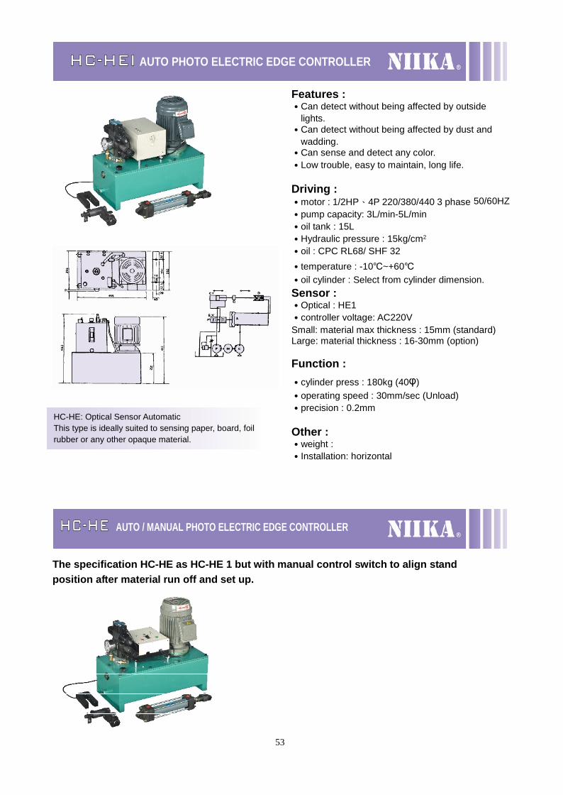
HC-HEI AUTO PHOTO ELECTRIC EDGE CONTROLLER
HC-HE AUTO / MANUAL PHOTO ELECTRIC EDGE CONTROLLER
The specification HC-HE as HC-HE 1 but with manual control switch to align standposition after material run off and set up.
HC-HE: Optical Sensor AutomaticThis type is ideally suited to sensing paper, board, foilrubber or any other opaque material.
Features :˙Can detect without being affected by outside
lights.˙Can detect without being affected by dust and
wadding.˙Can sense and detect any color.˙Low trouble, easy to maintain, long life.
Driving :˙motor : 1/2HP、4P 220/380/440 3 phase 50/60HZ˙pump capacity: 3L/min-5L/min˙oil tank : 15L˙Hydraulic pressure : 15kg/cm2
˙oil : CPC RL68/ SHF 32˙temperature : -10℃~+60℃˙oil cylinder : Select from cylinder dimension.Sensor :˙Optical : HE1˙controller voltage: AC220VSmall: material max thickness : 15mm (standard)Large: material thickness : 16-30mm (option)
Function :˙cylinder press : 180kg (40φ)˙operating speed : 30mm/sec (Unload)˙precision : 0.2mm
Other :˙weight :˙Installation: horizontal
54
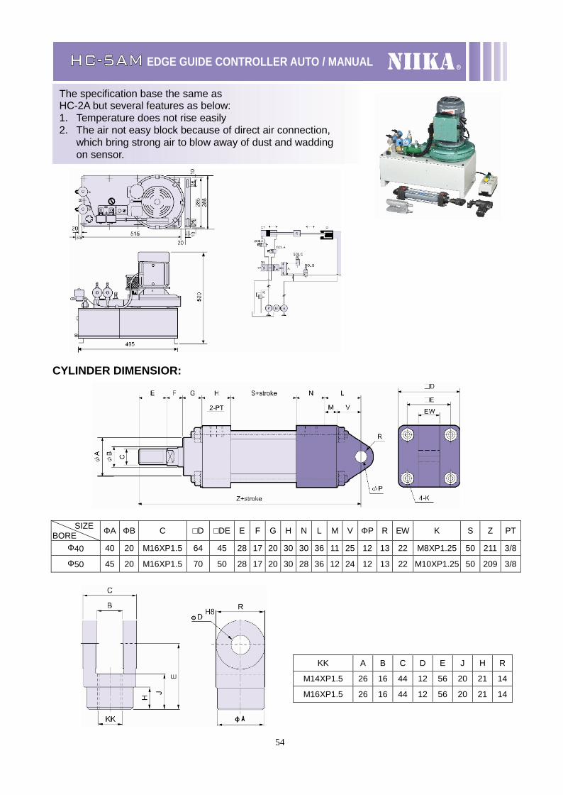
HC-5AM EDGE GUIDE CONTROLLER AUTO / MANUAL
CYLINDER DIMENSIOR:
SIZEBORE ΦA ΦB C □D □DE E F G H N L M V ΦP R EW K S Z PT
Φ40 40 20 M16XP1.5 64 45 28 17 20 30 30 36 11 25 12 13 22 M8XP1.25 50 211 3/8
Φ50 45 20 M16XP1.5 70 50 28 17 20 30 28 36 12 24 12 13 22 M10XP1.25 50 209 3/8
KK A B C D E J H R
M14XP1.5 26 16 44 12 56 20 21 14
M16XP1.5 26 16 44 12 56 20 21 14
The specification base the same asHC-2A but several features as below:1. Temperature does not rise easily2. The air not easy block because of direct air connection,
which bring strong air to blow away of dust and waddingon sensor.
55
HC-2A
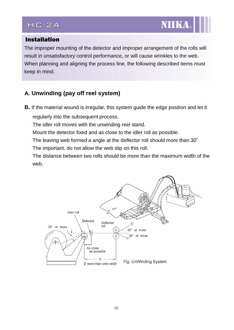
InstallationThe improper mounting of the detector and improper arrangement of the rolls willresult in unsatisfactory control performance, or will cause wrinkles to the web.When planning and aligning the process line, the following described items mustkeep in mind.
A. Unwinding (pay off reel system)
B. If the material wound is irregular, this system guide the edge position and let it
regularly into the subsequent process.The idler roll moves with the unwinding reel stand.Mount the detector fixed and as close to the idler roll as possible.The leaving web formed a angle at the deflector roll should more than 30˚The important, do not allow the web slip on this roll.The distance between two rolls should be more than the maximum width of theweb.

55
56
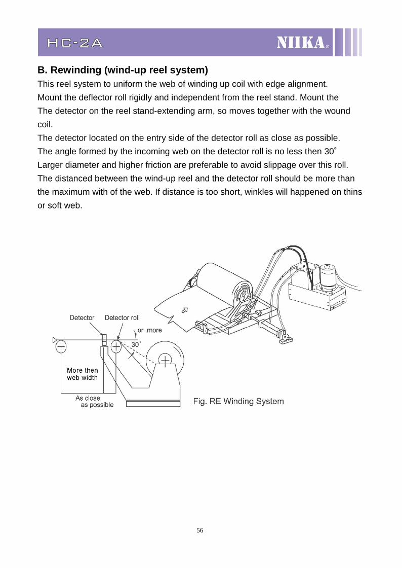
HC-2A
B. Rewinding (wind-up reel system)This reel system to uniform the web of winding up coil with edge alignment.Mount the deflector roll rigidly and independent from the reel stand. Mount theThe detector on the reel stand-extending arm, so moves together with the woundcoil.The detector located on the entry side of the detector roll as close as possible.The angle formed by the incoming web on the detector roll is no less then 30˚Larger diameter and higher friction are preferable to avoid slippage over this roll.The distanced between the wind-up reel and the detector roll should be more thanthe maximum with of the web. If distance is too short, winkles will happened on thinsor soft web.
57
Electric web guide
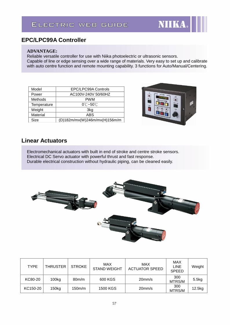
EPC/LPC99A Controller
ADVANTAGE:Reliable versatile controller for use with Niika photoelectric or ultrasonic sensors.Capable of line or edge sensing over a wide range of materials. Very easy to set up and calibratewith auto centre function and remote mounting capability. 3 functions for Auto/Manual/Centering.
Linear Actuators
Electromechanical actuators with built in end of stroke and centre stroke sensors.Electrical DC Servo actuator with powerful thrust and fast response.Durable electrical construction without hydraulic piping, can be cleaned easily.
Model EPC/LPC99A ControlsPower AC100V-240V 50/60HZMethods PWMTemperature 0℃~50℃Weight 3kgMaterial ABSSize (D)182m/mx(W)246m/mx(H)156m/m
TYPE THRUSTER STROKE MAXSTAND WEIGHT
MAXACTUATOR SPEED
MAXLINE
SPEEDWeight
KC80-20 100kg 80m/m 600 KGS 20mm/s 300MTRS/M 5.5kg
KC150-20 150kg 150m/m 1500 KGS 20mm/s 300MTRS/M 12.5kg
58
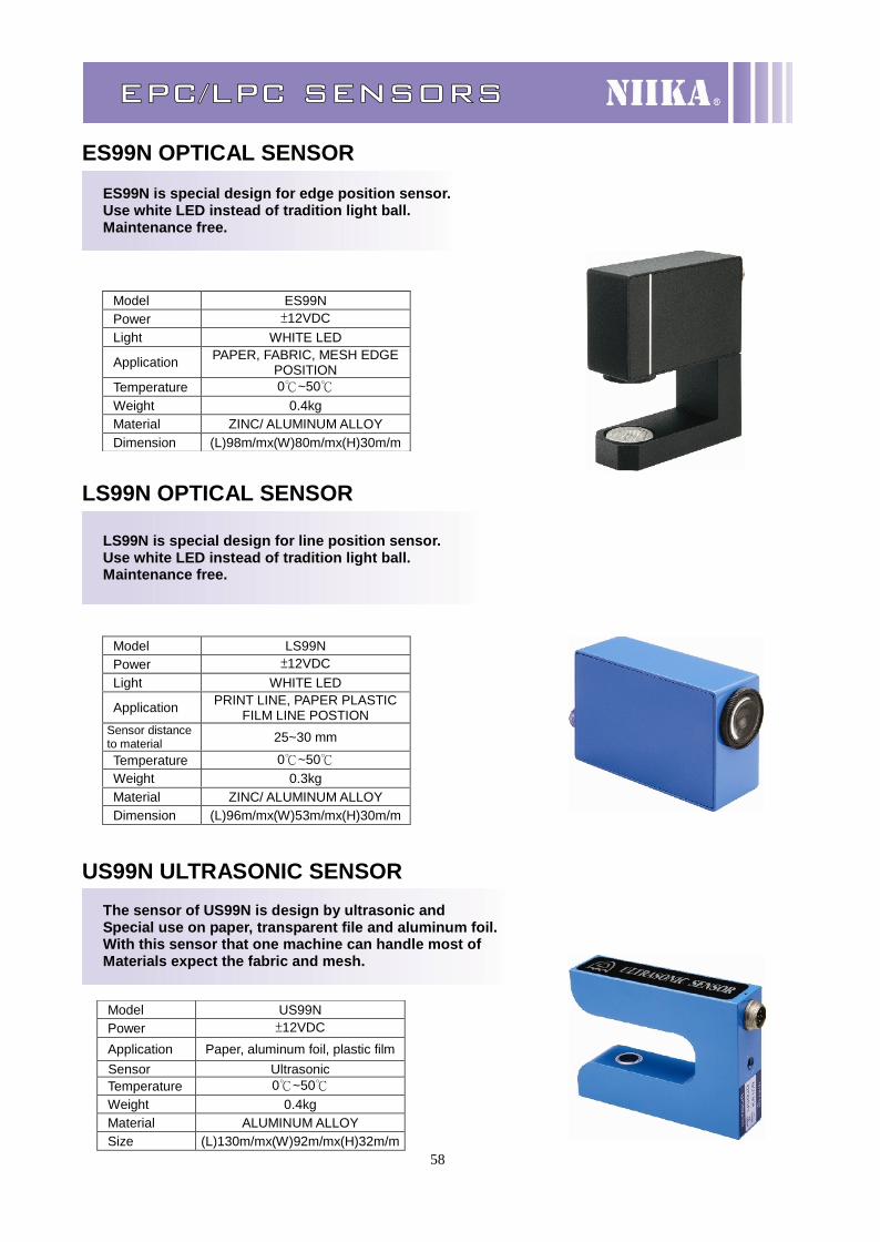
EPC/LPC SENSORS
ES99N OPTICAL SENSORES99N is special design for edge position sensor.Use white LED instead of tradition light ball.Maintenance free.
LS99N OPTICAL SENSOR
LS99N is special design for line position sensor.Use white LED instead of tradition light ball.Maintenance free.
US99N ULTRASONIC SENSORThe sensor of US99N is design by ultrasonic andSpecial use on paper, transparent file and aluminum foil.With this sensor that one machine can handle most ofMaterials expect the fabric and mesh.
Model ES99NPower ±12VDCLight WHITE LED
Application PAPER, FABRIC, MESH EDGEPOSITION
Temperature 0℃~50℃Weight 0.4kgMaterial ZINC/ ALUMINUM ALLOYDimension (L)98m/mx(W)80m/mx(H)30m/m
Model LS99NPower ±12VDCLight WHITE LED
Application PRINT LINE, PAPER PLASTICFILM LINE POSTION
Sensor distanceto material 25~30 mm
Temperature 0℃~50℃Weight 0.3kgMaterial ZINC/ ALUMINUM ALLOYDimension (L)96m/mx(W)53m/mx(H)30m/m
Model US99NPower ±12VDCApplication Paper, aluminum foil, plastic filmSensor UltrasonicTemperature 0℃~50℃Weight 0.4kgMaterial ALUMINUM ALLOYSize (L)130m/mx(W)92m/mx(H)32m/m


![Midea [MCAC-2011-05] Air cooled Modular Chiller & Fan Coil ... · Title: Midea [MCAC-2011-05] Air cooled Modular Chiller & Fan Coil Unit.pdf Author: CristiM Created Date: 3/15/2012](https://img.pdfslide.net/doc/110x75/5ad5cf287f8b9a177c8d7948/midea-mcac-2011-05-air-cooled-modular-chiller-fan-coil-midea-mcac-2011-05.jpg)


![Midea [MCAC-2011-05] Air cooled Modular Chiller & Fan Coil](https://img.pdfslide.net/doc/110x75/61da829d9b2d7e3642383753/midea-mcac-2011-05-air-cooled-modular-chiller-amp-fan-coil-.jpg)