Embed Size (px)
Citation preview
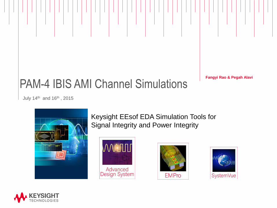
PAM-4 IBIS AMI Channel Simulations Fangyi Rao & Pegah Alavi
July 14th and 16th , 2015
Keysight EEsof EDA Simulation Tools for
Signal Integrity and Power Integrity
Page
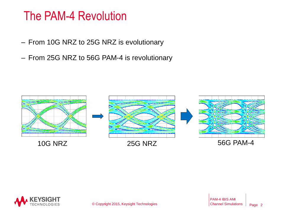
The PAM-4 Revolution
PAM-4 IBIS AMI
Channel Simulations © Copyright 2015, Keysight Technologies
– From 10G NRZ to 25G NRZ is evolutionary
– From 25G NRZ to 56G PAM-4 is revolutionary
10G NRZ 25G NRZ 56G PAM-4
2
Page
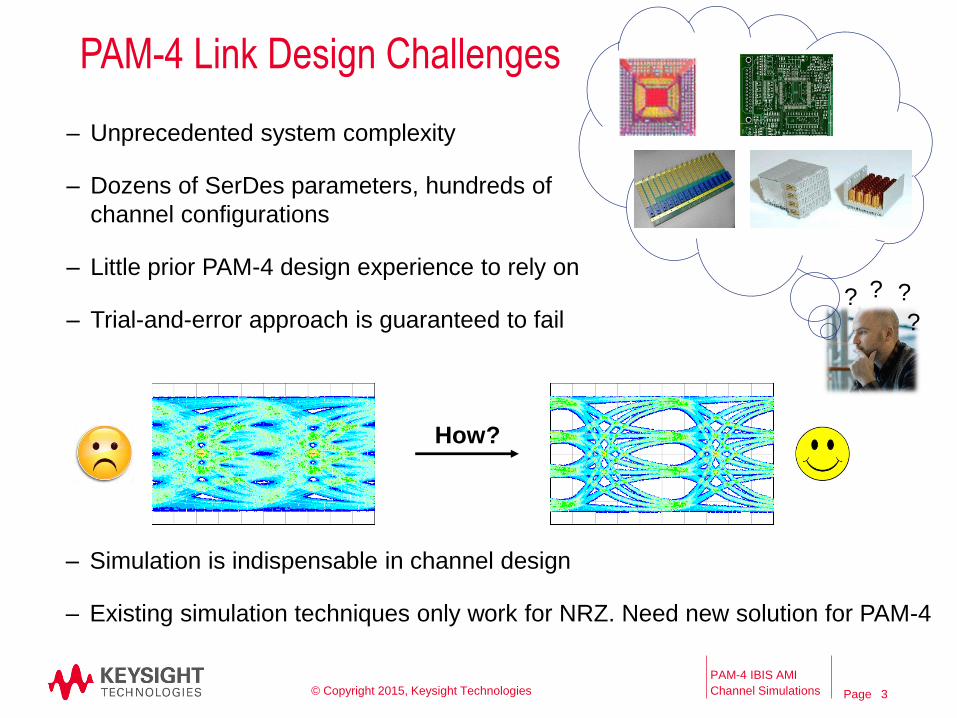
PAM-4 Link Design Challenges
PAM-4 IBIS AMI
Channel Simulations © Copyright 2015, Keysight Technologies
– Unprecedented system complexity
– Dozens of SerDes parameters, hundreds of
channel configurations
– Little prior PAM-4 design experience to rely on
– Trial-and-error approach is guaranteed to fail
– Simulation is indispensable in channel design
– Existing simulation techniques only work for NRZ. Need new solution for PAM-4
How?
3
? ?
?
?
PageAgenda
– Challenges in PAM-4 Link Designs
– Solutions for Simulating PAM-4 Links with IBIS-AMI Models
– Demo
– Q&A
4PAM-4 IBIS AMI Channel Simulations
© Copyright 2015, Keysight Technologies
4
Page
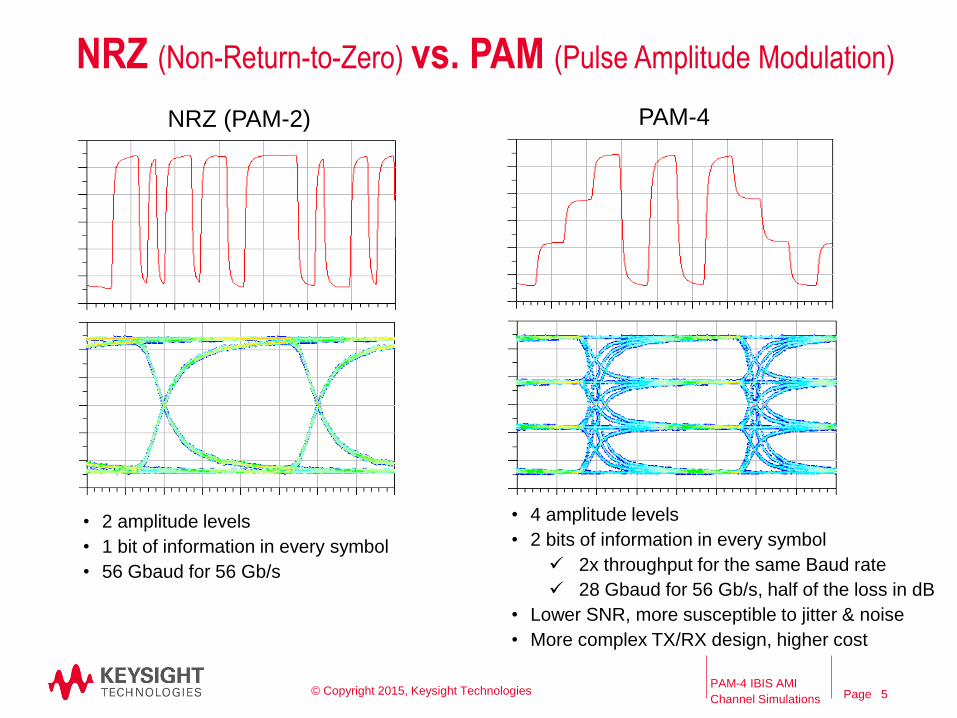
NRZ (Non-Return-to-Zero) vs. PAM (Pulse Amplitude Modulation)
NRZ (PAM-2) PAM-4
• 2 amplitude levels
• 1 bit of information in every symbol
• 56 Gbaud for 56 Gb/s
• 4 amplitude levels
• 2 bits of information in every symbol
2x throughput for the same Baud rate
28 Gbaud for 56 Gb/s, half of the loss in dB
• Lower SNR, more susceptible to jitter & noise
• More complex TX/RX design, higher cost
PAM-4 IBIS AMI
Channel Simulations © Copyright 2015, Keysight Technologies 5
Page
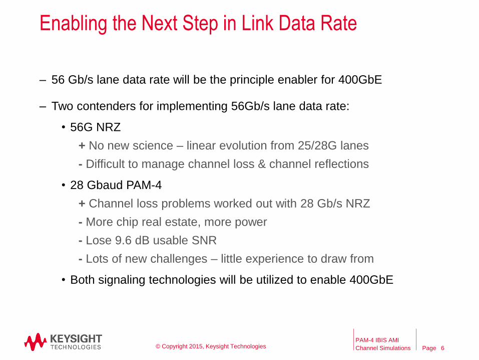
Enabling the Next Step in Link Data Rate
– 56 Gb/s lane data rate will be the principle enabler for 400GbE
– Two contenders for implementing 56Gb/s lane data rate:
• 56G NRZ
+ No new science – linear evolution from 25/28G lanes
- Difficult to manage channel loss & channel reflections
• 28 Gbaud PAM-4
+ Channel loss problems worked out with 28 Gb/s NRZ
- More chip real estate, more power
- Lose 9.6 dB usable SNR
- Lots of new challenges – little experience to draw from
• Both signaling technologies will be utilized to enable 400GbE
PAM-4 IBIS AMI
Channel Simulations © Copyright 2015, Keysight Technologies 6
Page
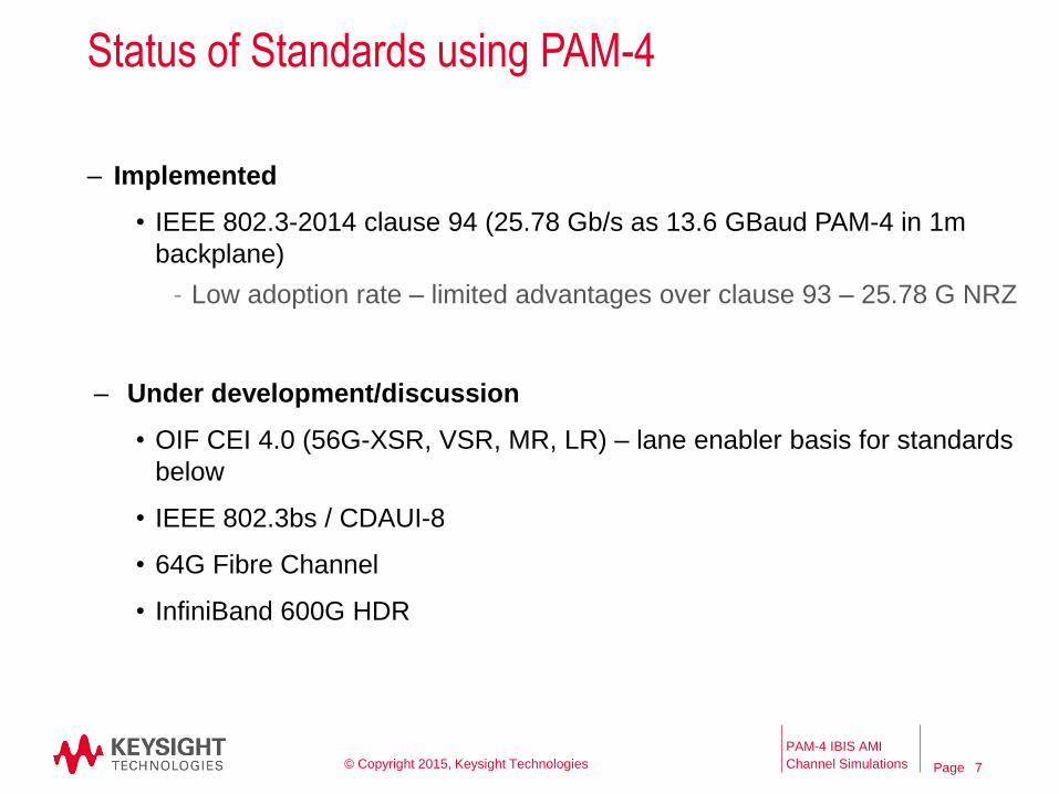
Status of Standards using PAM-4
– Implemented
• IEEE 802.3-2014 clause 94 (25.78 Gb/s as 13.6 GBaud PAM-4 in 1m
backplane)
- Low adoption rate – limited advantages over clause 93 – 25.78 G NRZ
– Under development/discussion
• OIF CEI 4.0 (56G-XSR, VSR, MR, LR) – lane enabler basis for standards
below
• IEEE 802.3bs / CDAUI-8
• 64G Fibre Channel
• InfiniBand 600G HDR
PAM-4 IBIS AMI
Channel Simulations © Copyright 2015, Keysight Technologies 7
Page
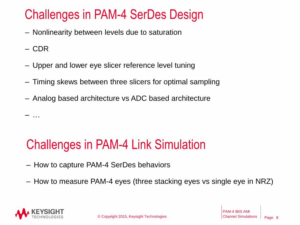
Challenges in PAM-4 SerDes Design
– Nonlinearity between levels due to saturation
– CDR
– Upper and lower eye slicer reference level tuning
– Timing skews between three slicers for optimal sampling
– Analog based architecture vs ADC based architecture
– …
PAM-4 IBIS AMI
Channel Simulations © Copyright 2015, Keysight Technologies
Challenges in PAM-4 Link Simulation
– How to capture PAM-4 SerDes behaviors
– How to measure PAM-4 eyes (three stacking eyes vs single eye in NRZ)
8
Page
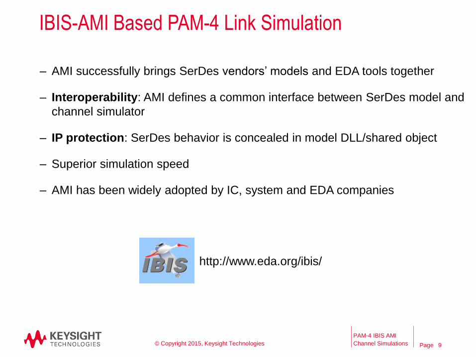
IBIS-AMI Based PAM-4 Link Simulation
– AMI successfully brings SerDes vendors’ models and EDA tools together
– Interoperability: AMI defines a common interface between SerDes model and
channel simulator
– IP protection: SerDes behavior is concealed in model DLL/shared object
– Superior simulation speed
– AMI has been widely adopted by IC, system and EDA companies
PAM-4 IBIS AMI
Channel Simulations © Copyright 2015, Keysight Technologies
http://www.eda.org/ibis/
9
Page
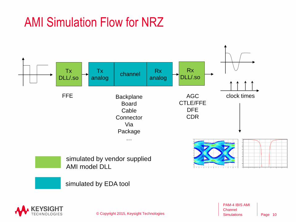
PAM-4 IBIS AMI
Channel
Simulations
AMI Simulation Flow for NRZ
Tx
DLL/.so
Tx
analogchannel
Rx
analog
Rx
DLL/.so
clock timesFFE Backplane
Board
Cable
Connector
Via
Package
…
AGC
CTLE/FFE
DFE
CDR
simulated by vendor supplied
AMI model DLL
simulated by EDA tool
© Copyright 2015, Keysight Technologies 10
Page
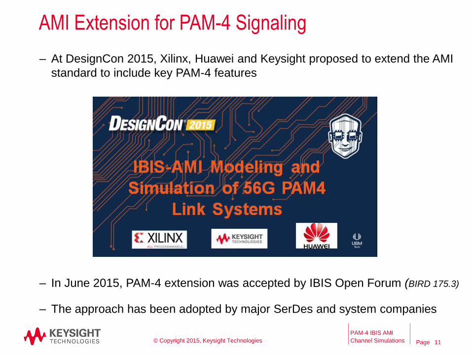
AMI Extension for PAM-4 Signaling
– At DesignCon 2015, Xilinx, Huawei and Keysight proposed to extend the AMI
standard to include key PAM-4 features
PAM-4 IBIS AMI
Channel Simulations © Copyright 2015, Keysight Technologies
– In June 2015, PAM-4 extension was accepted by IBIS Open Forum (BIRD 175.3)
– The approach has been adopted by major SerDes and system companies
11
Page
PAM-4 IBIS AMI
Channel
Simulations
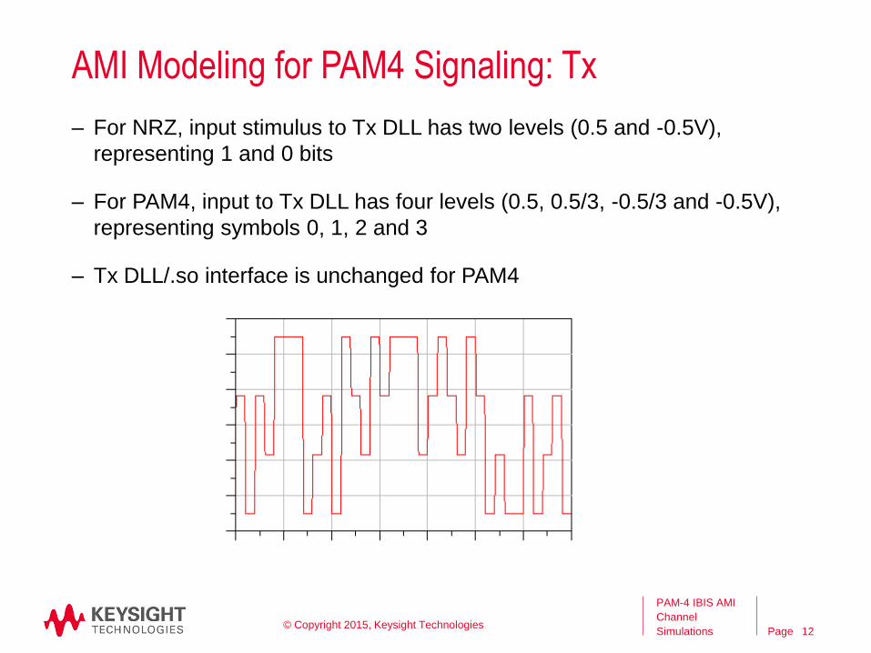
AMI Modeling for PAM4 Signaling: Tx
– For NRZ, input stimulus to Tx DLL has two levels (0.5 and -0.5V),
representing 1 and 0 bits
– For PAM4, input to Tx DLL has four levels (0.5, 0.5/3, -0.5/3 and -0.5V),
representing symbols 0, 1, 2 and 3
– Tx DLL/.so interface is unchanged for PAM4
© Copyright 2015, Keysight Technologies12
Page
PAM-4 IBIS AMI
Channel
Simulations
Tx AMI Reserved Parameters
– String. Allowed values are “NRZ” and “PAM4”
– Optional. Default is “NRZ”
Modulation
PAM4_Mapping
– String of four non-repeated integers 0, 1, 2 and 3 (e.g. “0123”)
– Bit pairs 00, 01, 10 and 11 map to symbol levels specified by 1st, 2nd, 3rd
and 4th integers, respectively
– Optional. Default is “0132” (Gray coding)
© Copyright 2015, Keysight Technologies 13
Page
PAM-4 IBIS AMI
Channel
Simulations
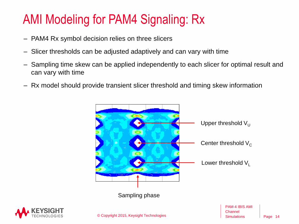
AMI Modeling for PAM4 Signaling: Rx
– PAM4 Rx symbol decision relies on three slicers
– Slicer thresholds can be adjusted adaptively and can vary with time
– Sampling time skew can be applied independently to each slicer for optimal result and
can vary with time
– Rx model should provide transient slicer threshold and timing skew information
Upper threshold VU
Center threshold VC
Lower threshold VL
Sampling phase
© Copyright 2015, Keysight Technologies 14
Page
PAM-4 IBIS AMI
Channel
Simulations
Rx AMI Reserved Parameters
– Float. Upper, center and lower slicer thresholds
– Optional. If not provided by models, EDA tools have to guess their values
for SER calculations
PAM4_UpperThreshold, PAM4_CenterThreshold, PAM4_LowerThreshold
PAM4_UpperEyeOffset, PAM4_CenterEyeOffset, PAM4_LowerEyeOffset
Rx model can update values of these parameters in AMI_Init and
AMI_GetWave and return them through the AMI_parameters_out string
argument
– Float. Upper, center and lower slicer sample time offsets relative to clock
times
– Optional. Default is 0
© Copyright 2015, Keysight Technologies 15
Page
PAM-4 IBIS AMI
Channel
Simulations
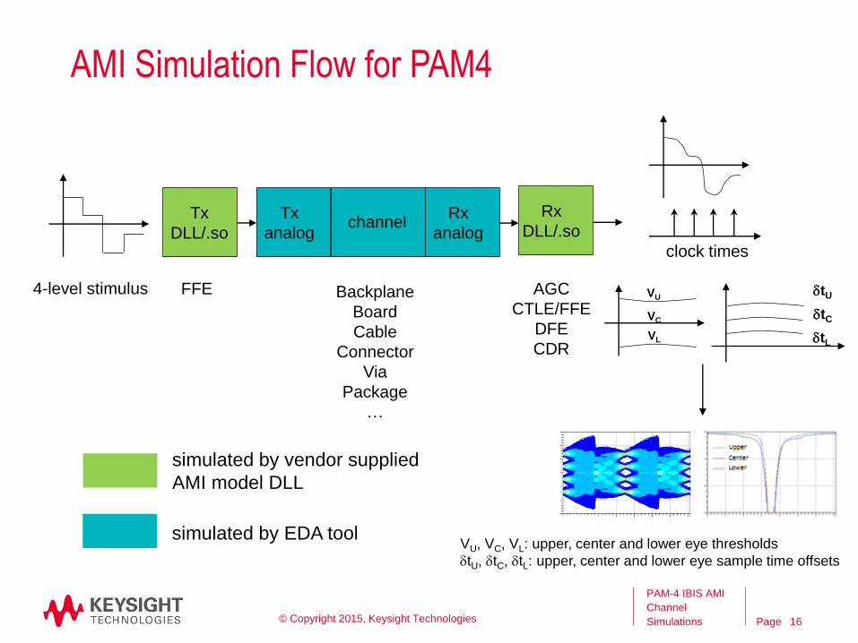
AMI Simulation Flow for PAM4
Tx
DLL/.so
Tx
analogchannel
Rx
analog
Rx
DLL/.so
clock times
VU
VC
VL
FFE Backplane
Board
Cable
Connector
Via
Package
…
AGC
CTLE/FFE
DFE
CDR
simulated by vendor supplied
AMI model DLL
simulated by EDA tool
dtU
dtL
dtC
VU, VC, VL: upper, center and lower eye thresholds
dtU, dtC, dtL: upper, center and lower eye sample time offsets
4-level stimulus
© Copyright 2015, Keysight Technologies 16
Page
PAM-4 IBIS AMI
Channel
Simulations
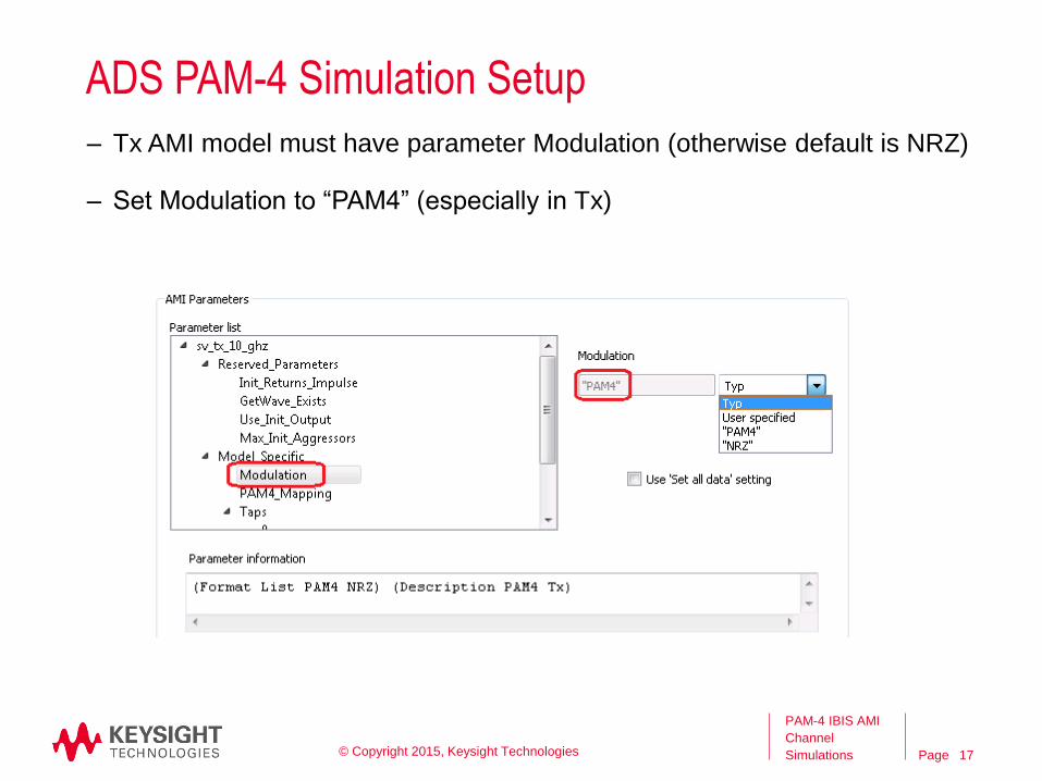
ADS PAM-4 Simulation Setup
– Tx AMI model must have parameter Modulation (otherwise default is NRZ)
– Set Modulation to “PAM4” (especially in Tx)
© Copyright 2015, Keysight Technologies 17
Page
PAM-4 IBIS AMI
Channel
Simulations
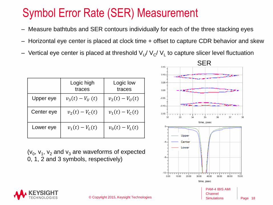
Symbol Error Rate (SER) Measurement– Measure bathtubs and SER contours individually for each of the three stacking eyes
– Horizontal eye center is placed at clock time + offset to capture CDR behavior and skew
– Vertical eye center is placed at threshold VU/ VC/ VL to capture slicer level fluctuation
(v0, v1, v2 and v3 are waveforms of expected
0, 1, 2 and 3 symbols, respectively)
Logic high
traces
Logic low
traces
Upper eye 𝑣3 𝑡 − 𝑉𝑈 (𝑡) 𝑣2 𝑡 − 𝑉𝑈(𝑡)
Center eye 𝑣2 𝑡 − 𝑉𝐶(𝑡) 𝑣1 𝑡 − 𝑉𝐶(𝑡)
Lower eye 𝑣1 𝑡 − 𝑉𝐿(𝑡) 𝑣0 𝑡 − 𝑉𝐿(𝑡)
SER
© Copyright 2015, Keysight Technologies 18
Page
PAM-4 IBIS AMI
Channel
Simulations
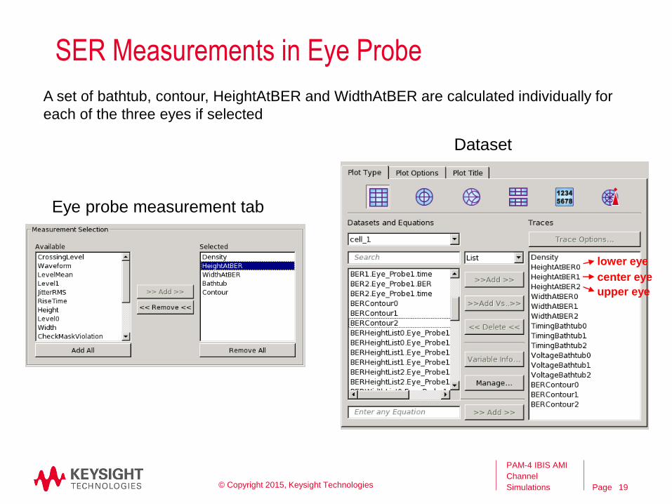
SER Measurements in Eye Probe
lower eye
center eye
upper eye
Eye probe measurement tab
Dataset
A set of bathtub, contour, HeightAtBER and WidthAtBER are calculated individually for
each of the three eyes if selected
© Copyright 2015, Keysight Technologies 19
Page
PAM-4 IBIS AMI
Channel
Simulations
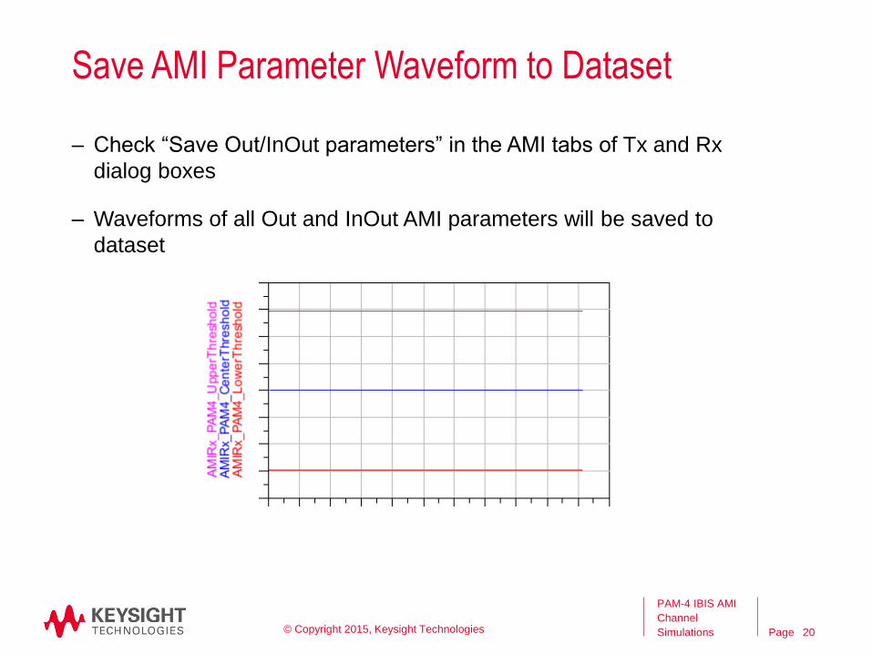
Save AMI Parameter Waveform to Dataset
– Check “Save Out/InOut parameters” in the AMI tabs of Tx and Rx
dialog boxes
– Waveforms of all Out and InOut AMI parameters will be saved to
dataset
© Copyright 2015, Keysight Technologies 20
Page
PAM-4 IBIS AMI
Channel
Simulations
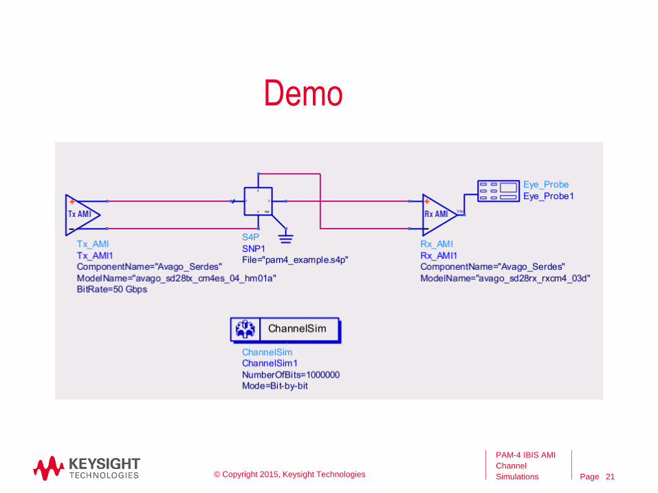
Demo
© Copyright 2015, Keysight Technologies 21
Page
PAM-4 IBIS AMI
Channel
Simulations
Q & A
© Copyright 2015, Keysight Technologies 22
Page
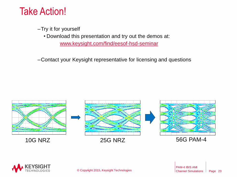
Take Action!
PAM-4 IBIS AMI
Channel Simulations
10G NRZ 25G NRZ 56G PAM-4
–Try it for yourself
• Download this presentation and try out the demos at:
www.keysight.com/find/eesof-hsd-seminar
–Contact your Keysight representative for licensing and questions
© Copyright 2015, Keysight Technologies 23
Page
PAM-4 IBIS AMI
Channel
Simulations
Thank you
© Copyright 2015, Keysight Technologies 24