Embed Size (px)
Citation preview

Fast and Accurate Fault Location using Synchrophasors
S.D. PICARD, M.G. ADAMIAK
GE Digital Energy
Canada
V. MADANI
Pacific Gas & Electric
United States of America
SUMMARY
Fast and accurate fault location is critical to restoration of the power system. Deployment of
production grade Phasor Measurement Unit (PMU) based on the latest IEEE C37.118.1
measurement standards using high-speed “P Class” data makes accurate fault location
possible. Multi-terminal PMU data and decentralized PDC storage can easily be leveraged to
not only obtain affordable and accurate fault location but also provide the operator with key
information. By-products of this process are dynamic computation of line positive-sequence
impedance and fault resistance.
This paper presents the implementation of a proven multi-ended fault locator [1] with
manufacturer-independent synchrophasor sources with data being stored in a decentralized
fashion. The rationale motivating this implementation is to take advantage of readily
available PMU data at various voltage levels, facilitating economical and accurate fault
location using PMU devices.
The calculations are performed at an Engineering Data Concentrator (EDC) which may be
located outside of the Control Center environment. When a fault trigger indication is raised
by the PMU and stored on the PDC Historian, it becomes detectable by the EDC which will
collect datasets from the relevant PMUs, analyses the data and, if a fault is identified,
performs the fault location calculations. Summary results are then passed on to the Control
Center environment (typically EMS for transmission system) while the details are logged
locally for further analysis by the engineering department.
Requirements for assuring accurate fault location such as timing source accuracy and the
selection of time window for fault location calculation are described. Simulation results
demonstrating impact of DC offset, load, and fault resistance are presented. The Testing
approach is also addressed to ensure accuracy for various fault types and scenario (high
impedance fault, slow operating circuit breaker, lines with mutual coupling, intermittent
communication).
21, rue d’Artois, F-75008 PARIS CIGRE US National Committee
http : //www.cigre.org 2014 Grid of the Future Symposium

1
KEYWORDS
Synchrophasor – PMU – Fault Location – IEEE C37.118 – IEEE 61850-90-5 – PDC – IRIG-B –
IEEE 1588
2
Introduction
The adoption of Synchrophasor technology, especially when “P” or Protection Class measurements is
deployed by electrical utilities (more than 1000 PMUs installed in North America [2]) opens the door
to Fault Location not only at a scale unanticipated before but also in a centralized fashion. When
properly engineered and with proper measurement and sampling rates, Fault Location is an additional
application that can rapidly provide valuable information at a low incremental cost. The PMU device
used for fault location application is required to be equipped beyond measurement and streaming
phasor values. Some fault detection logic, some status measurement capabilities, plus capability to
register fault triggers are needed. For example, some level of user programming to define triggers for
“fault” is beneficial and makes fault location process efficient. Likewise, the PMU device capable of
measuring all three phase voltage and current is advantageous in order to determine fault type.
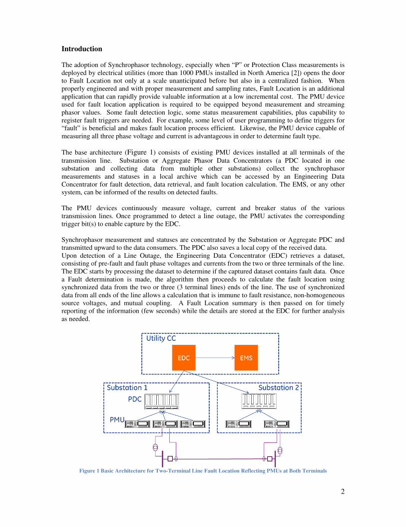
The base architecture (Figure 1) consists of existing PMU devices installed at all terminals of the
transmission line. Substation or Aggregate Phasor Data Concentrators (a PDC located in one
substation and collecting data from multiple other substations) collect the synchrophasor
measurements and statuses in a local archive which can be accessed by an Engineering Data
Concentrator for fault detection, data retrieval, and fault location calculation. The EMS, or any other
system, can be informed of the results on detected faults.
The PMU devices continuously measure voltage, current and breaker status of the various
transmission lines. Once programmed to detect a line outage, the PMU activates the corresponding
trigger bit(s) to enable capture by the EDC.
Synchrophasor measurement and statuses are concentrated by the Substation or Aggregate PDC and
transmitted upward to the data consumers. The PDC also saves a local copy of the received data.
Upon detection of a Line Outage, the Engineering Data Concentrator (EDC) retrieves a dataset,
consisting of pre-fault and fault phase voltages and currents from the two or three terminals of the line.
The EDC starts by processing the dataset to determine if the captured dataset contains fault data. Once
a Fault determination is made, the algorithm then proceeds to calculate the fault location using
synchronized data from the two or three (3 terminal lines) ends of the line. The use of synchronized
data from all ends of the line allows a calculation that is immune to fault resistance, non-homogeneous
source voltages, and mutual coupling. A Fault Location summary is then passed on for timely
reporting of the information (few seconds) while the details are stored at the EDC for further analysis
as needed.
Figure 1 Basic Architecture for Two-Terminal Line Fault Location Reflecting PMUs at Both Terminals

3
The comparison between this fault location implementation and single-ended fault location
traditionally performed on the individual relay is presented in [1].
System Components Requirements
Measurement: Accuracy of the Phasor Measurement Unit is critical as the phase voltages and currents
measured by the PMU are the basis of the Fault Location algorithm. The C37.118.1 Synchrophasor
Standard defines a measurement metric known at Total Vector Error (TVE) which incorporates errors
in magnitude, angle, and time. Looking forward to the interoperability of devices sourcing data for
this purpose, compliance to the Synchrophasor standard becomes paramount. The NIST metrology
and other conformance validation facilities have developed testing methodologies that guarantee
conformance to the standard. A summary on testing was presented by the NASPI Task Force on
Testing and Certification [3].
Timing: IEEE Std C37.118.1 specifies a maximum TVE of 1%. In the absence of magnitude error, this
translates to an angular error of 0.573º or, in terms of time, 26.5 µs. The time sources currently used
for synchrophasor application are: direct GPS input, IRIG-B and/or IEEE Std. 1588. Direct GPS input
accuracy depends on the actual PMU device. Both DC Level Shift IRIG-B and IEEE 1588 (time sync
over Ethernet) provide accuracy better than 1 µs.
Dataset: The algorithm implementation requires voltage and current at each of the 2 or 3 terminals of
the transmission line and the status and trigger bits, in addition to the transmission line parameters.
The lines parameters are manually entered at the EDC’s HMI and are typically calculated by the
Utility as part of their power system modelling. As mentioned above, one of the by-products of the
calculation is the measurement of the dynamic line impedance. As such, the “setting” impedance can
be validated against the measured impedance
The magnitude and angle of the following quantities are assembled together for processing:
• Va, Vb, Vc
• Ia, Ib, Ic.
A modified Clark Transform is used on the single phase values to enable analysis in a single network
model.
In addition to the measured quantities, the following line parameters are also required for a 2- (or 3-)
terminal line:
• Line (tap) length
• Line (tap) complex positive-sequence impedance
• Line (tap) complex zero-sequence impedance
• Line (tap) complex mutual impedance
Note that the Zero and Mutual impedances are only needed in the optional calculation of the fault
resistance.
Communication: The communication bandwidth required for implementing the proposed system is
actually rather small. The status and trigger bit are monitored regularly. The use of trigger bit allows
“data on demand” therefore minimizing communication bandwidth to the PDC to only those times and
to the specific data required for the fault location calculation.
It is equally important to recognize the measurement sampling rate for fault location calculation which
is presently computed at a rate of 120 measurements/sec.

4
Assuming a theoretical case of 1kB of payload for monitoring requests over TCP/IP and return of 2
words of Status and Triggers, this would result in 1040 Bytes in one direction and 42 Bytes in the
other direction, 120 times per second. That is 1038 kbps, around 1% of a Fast Ethernet connection for
the Status/Trigger bit monitoring.
In the case of a detected fault, an estimated 1 kB for the data request over TCP/IP and 5 kB of payload
would be transmitted. That represents a total of 51 kB which would be a small burst of data only
when a fault occurs.
Filter and window at PMU level: C37.118.1 specifies two admissible types of filtering, namely M
(Measurement) Class and P (Protection) Class. The M class data cannot be used because of the
inherent delays to filter the data as defined in C37.118.1. As indicated in the standard, the “P class is
intended for applications requiring fast response and mandates no explicit filtering. The letter P is
used since protection applications require fast response.” [4]. It is intended to allow the application
requiring the data to make use of it and any filtering will be by the specific application. The P class is
the preferred filtering to reduce reporting latency and avoid the long window of M-class filtering,
which would be longer than the fault window.
Data rate and window length: The amount of data needed from the PMUs at each end of the line for a
successful and accurate location depends on a number of factors including breaker opening time and
the critical clearing time of the power system based on the type of the fault, protective device
performance. Assuming a clearing time of 3 power cycles, and given that Fourier transform requires
at least ½ cycle to stabilize, a data rate of 120 frames per second would provide 5 samples of fault
data. As part of the fault location computation, the few first and last samples would be discarded,
leaving enough samples to provide accurate results. Higher data frames measurement and streaming
improves accuracy by providing additional samples for the computation and averaging of the fault
location.
In the System Validation (presented below), a window of 600 ms of data centered on the trigger point
is used, providing sufficient pre- and post-fault to ensure capture of the fault data. Additionally, the
pre-fault data is used to compute the dynamic line impedance.
Figure 2 Proof of Concept Test Facility
5
The choice of data rate also influences the order of the filter and thus the reporting latency. In that
respect, the choice of higher data rate works well in coordination with the use of the “P” class data and
filtering classifications described earlier.
System Validation
In order to test the Architecture shown in Figure 1, a Proof of Concept test facility (Figure 2) built
for several advanced applications of synchrophasor technology analytics was leveraged. A real-time
digital simulator (RTDS) modelled a portion of the power system consisting of 16 buses, 24
transmission lines (8 with series compensated lines) and 13 sources. The POC is engineered to create
a real-time environment. The simulator output is amplified to relay secondary-value voltages and
currents fed to the PMU devices. It also produces virtual PMU C37.118 data stream based on
simulated voltages, currents and statuses. The POC facility has in excess of 20 real PMU and 48
virtual PMUs for use in validating analytics including fault location applications. The architecture is
designed so that the PMU data streams from each end of the line are sent into different substation level
PDCs (Phasor Data Concentrators). The architecture was designed to emulate the field environment.
For example, for a two terminal line of 100 miles in length, it is likely that the PMU measurements
from each end of the line are streamed to local PDCs. As such, the fault location computation will
need data from multiple field PDCs in order to successfully perform multi-terminal fault location.
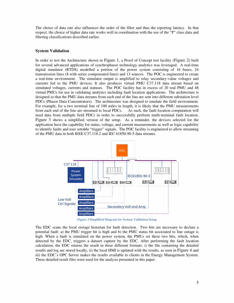
Figure 3 shows a simplified version of the setup. As a reminder, the devices selected for the
application have the capability for status, voltage, and current measurements as well as logic capability
to identify faults and user settable “trigger” signals. The POC facility is engineered to allow streaming
of the PMU data in both IEEE C37.118.2 and IEC 61850-90-5 data streams.
Figure 3 Simplified Diagram for System Validation Setup
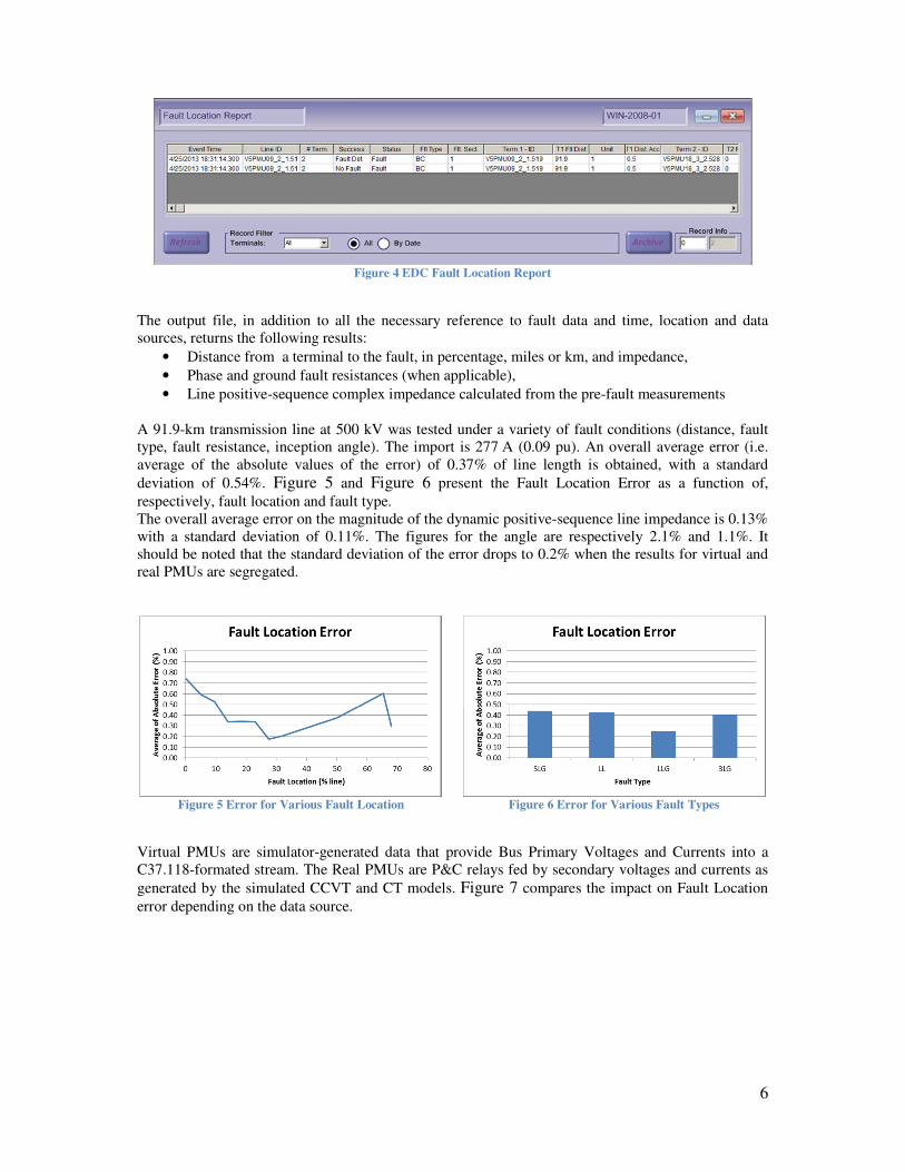
The EDC scans the local storage historian for fault detection. Two bits are necessary to declare a
potential fault: a) the PMU trigger bit is high and b) the PMU status bit associated to line outage is
high. When a fault is simulated on the power system, the PMUs set these two bits, which, when
detected by the EDC, triggers a dataset capture by the EDC. After performing the fault location
calculation, the EDC returns the result in three different formats: i) the file containing the detailed
results and log are stored locally, ii) the local HMI is updated with the results, as seen in Figure 4 and
iii) the EDC’s OPC Server makes the results available to clients in the Energy Management System.
These detailed result files were used for the analysis presented in this paper.
6
Figure 4 EDC Fault Location Report
The output file, in addition to all the necessary reference to fault data and time, location and data
sources, returns the following results:
• Distance from a terminal to the fault, in percentage, miles or km, and impedance,
• Phase and ground fault resistances (when applicable),
• Line positive-sequence complex impedance calculated from the pre-fault measurements
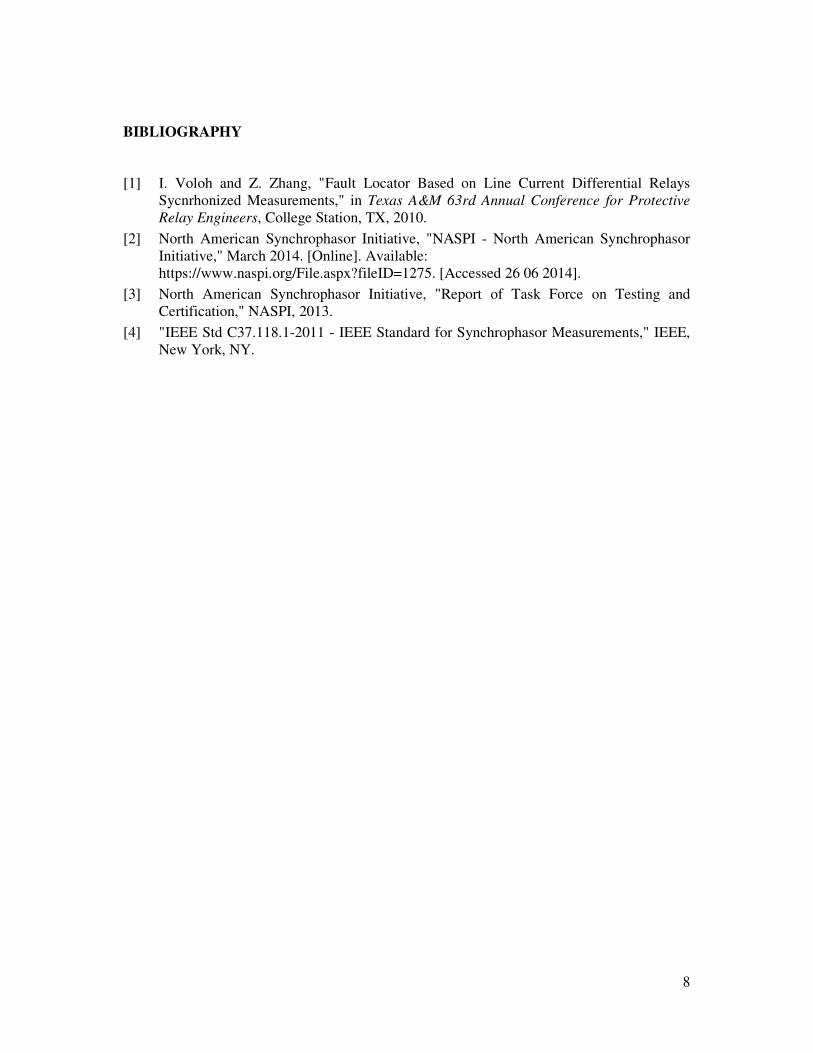
A 91.9-km transmission line at 500 kV was tested under a variety of fault conditions (distance, fault
type, fault resistance, inception angle). The import is 277 A (0.09 pu). An overall average error (i.e.
average of the absolute values of the error) of 0.37% of line length is obtained, with a standard
deviation of 0.54%. Figure 5 and Figure 6 present the Fault Location Error as a function of,
respectively, fault location and fault type.
The overall average error on the magnitude of the dynamic positive-sequence line impedance is 0.13%
with a standard deviation of 0.11%. The figures for the angle are respectively 2.1% and 1.1%. It
should be noted that the standard deviation of the error drops to 0.2% when the results for virtual and
real PMUs are segregated.
Figure 5 Error for Various Fault Location
Figure 6 Error for Various Fault Types
Virtual PMUs are simulator-generated data that provide Bus Primary Voltages and Currents into a
C37.118-formated stream. The Real PMUs are P&C relays fed by secondary voltages and currents as
generated by the simulated CCVT and CT models. Figure 7 compares the impact on Fault Location
error depending on the data source.

7
Figure 7 Error for Real and Virtual PMUs
Figure 8 Error for Various Ground Fault Resistance
The effect of fault resistance is shown in Figure 8 for a variety of ground fault (including single-line
to ground, two-lines to ground and three-lines to ground).
Finally, Figure 9 shows the PMU measurement for the Phase Current of a three-phase fault as it
appears in Figure 10. While phase A presents very little DC offset (compared to phases B and C), the
resulting PMU measurement are very similar for all three phases. The PMU effectively removes most
of the decaying DC component and thus provides solid foundations for the calculation of Fault
Location.
Figure 9 PMU Phase Current Figure 10 Fault Phase Current
Conclusion
High-speed synchrophasor data has been demonstrated to be effective in the multi-terminal calculation
of fault location. The synchronized approach is free from the effects of fault resistance, mutual
coupling, and non-homogeneous voltage angles. It is worth noting that if PMUs are streaming IEC
61850-90-5 in a multicast mode, the addition of the Fault Locator equipment does not require any
changes to PMU settings, only subscription to the streams by the Phasor Data Concentrator.
8
BIBLIOGRAPHY
[1] I. Voloh and Z. Zhang, "Fault Locator Based on Line Current Differential Relays
Sycnrhonized Measurements," in Texas A&M 63rd Annual Conference for Protective
Relay Engineers, College Station, TX, 2010.
[2] North American Synchrophasor Initiative, "NASPI - North American Synchrophasor
Initiative," March 2014. [Online]. Available:
https://www.naspi.org/File.aspx?fileID=1275. [Accessed 26 06 2014].
[3] North American Synchrophasor Initiative, "Report of Task Force on Testing and
Certification," NASPI, 2013.
[4] "IEEE Std C37.118.1-2011 - IEEE Standard for Synchrophasor Measurements," IEEE,
New York, NY.