Embed Size (px)
Citation preview
Fast False Path Identification Based on Functional Unsensitizability Using RTL Information
Presenter Yuki Yoshikawa1
2 Nara Institute of Science and Technology, Japan
1 Hiroshima City University, Japan
Satoshi Ohtake2, Tomoo Inoue1 and Hideo Fujiwara2
ASP-DAC 2009
*This work has been supported in part by STARC
2Outline
BackgroundFalse pathAdverse effect of false paths
– Over-testing of delay faults– Inaccurate estimation of a system clock period
Our proposed methodFalse path identification using RTL information
Experimental result
Conclusion
3Background
For high performance VLSIs,high quality delay fault testing, andaccurate estimation of a circuit delay is an important issue
False paths interfereaccurate timing delay testing
– Over-testingaccurate estimation of a system clock period
– Degradation of circuit performance
4False path
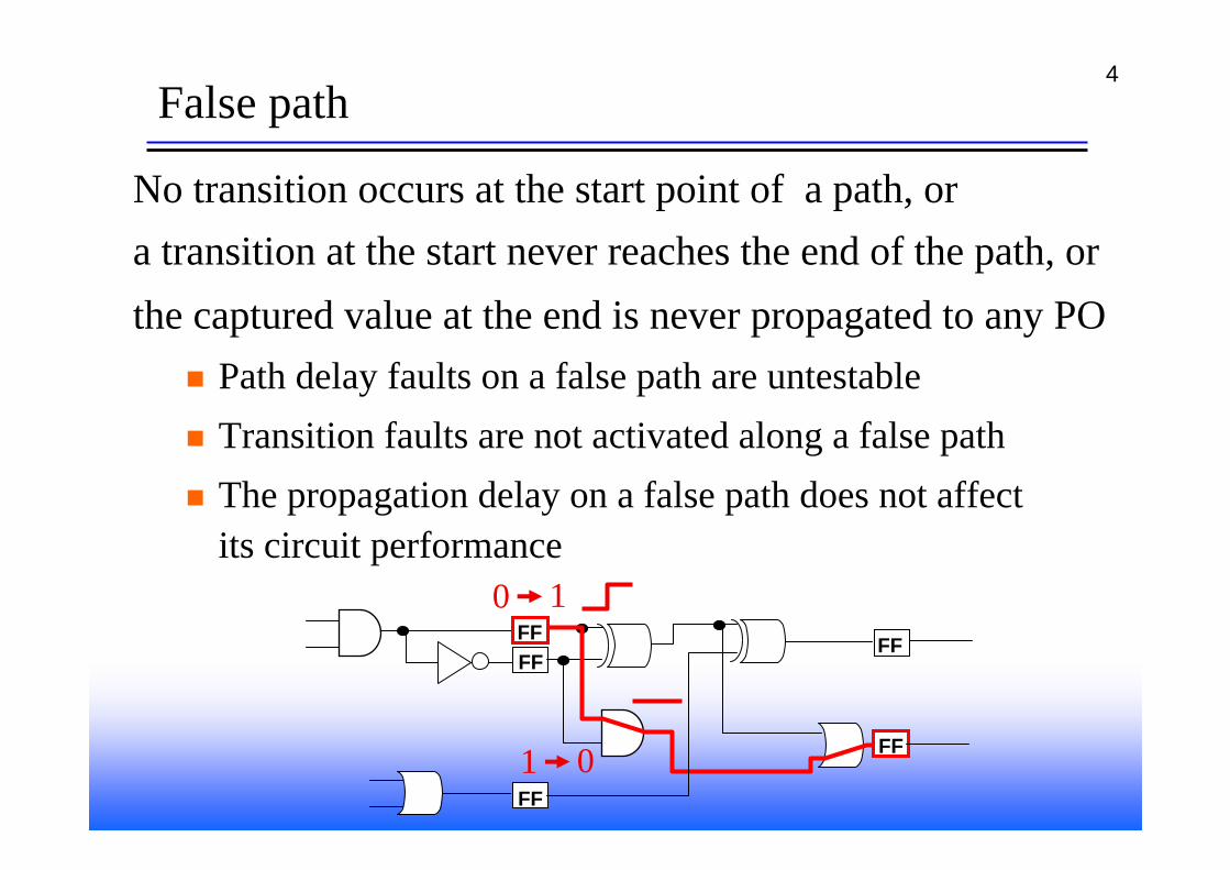
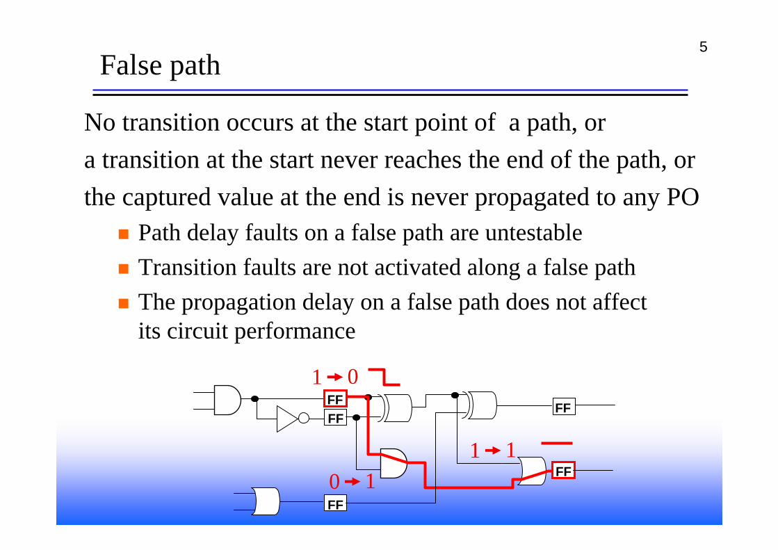
No transition occurs at the start point of a path, ora transition at the start never reaches the end of the path, orthe captured value at the end is never propagated to any PO
Path delay faults on a false path are untestableTransition faults are not activated along a false pathThe propagation delay on a false path does not affectits circuit performance
FFFF
FF
FF
FF
0 1
1 0
5False path
FFFF
FF
FF
FF
1 0
0 11 1
No transition occurs at the start point of a path, ora transition at the start never reaches the end of the path, orthe captured value at the end is never propagated to any PO
Path delay faults on a false path are untestableTransition faults are not activated along a false pathThe propagation delay on a false path does not affectits circuit performance
6Over-testing
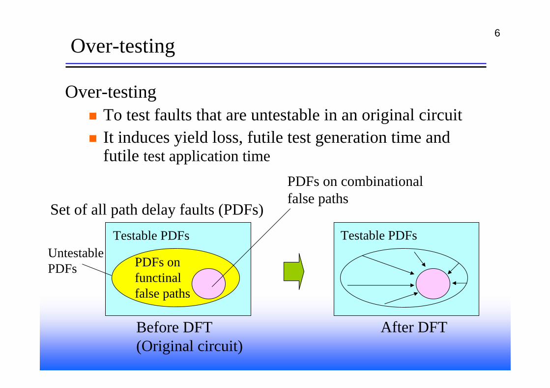
Over-testingTo test faults that are untestable in an original circuitIt induces yield loss, futile test generation time and futile test application time
Testable PDFs
PDFs on functinalfalse paths
PDFs on combinationalfalse paths
Set of all path delay faults (PDFs)
Before DFT(Original circuit)
After DFT
Testable PDFsUntestablePDFs
7Approach to over-testing reduction
A strategy for over-testing reductionFalse path identification for an original circuitExclusion of PDFs on the identified false pathsfrom the target of testing
To reduce over-testing, it is important to identifyas many false paths as possible with small computational time
8Inaccurate estimation of a system clock period
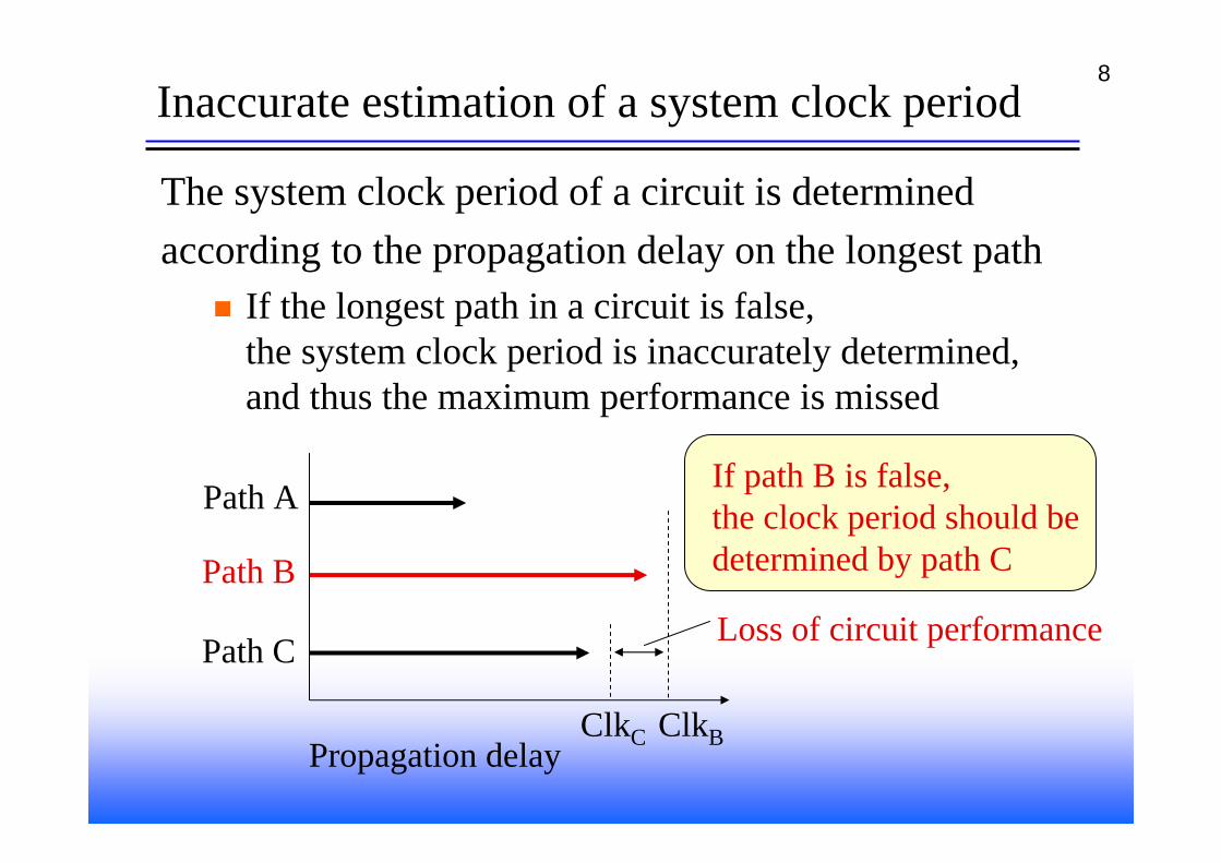
The system clock period of a circuit is determinedaccording to the propagation delay on the longest path
If the longest path in a circuit is false,the system clock period is inaccurately determined, and thus the maximum performance is missed
Path A
Path B
Path C
Propagation delay
If path B is false, the clock period should be determined by path C
ClkBClkC
Loss of circuit performance
9Related works
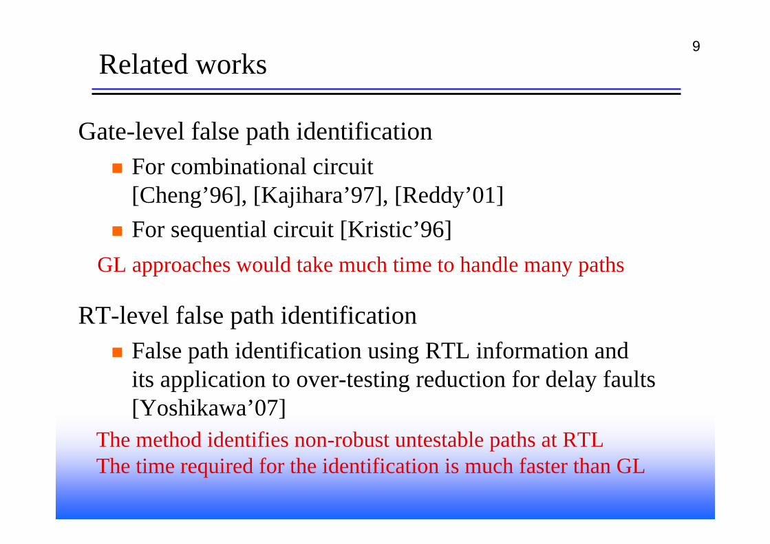
Gate-level false path identification For combinational circuit[Cheng’96], [Kajihara’97], [Reddy’01]For sequential circuit [Kristic’96]
RT-level false path identificationFalse path identification using RTL information andits application to over-testing reduction for delay faults[Yoshikawa’07]
GL approaches would take much time to handle many paths
The method identifies non-robust untestable paths at RTLThe time required for the identification is much faster than GL
10Research objective
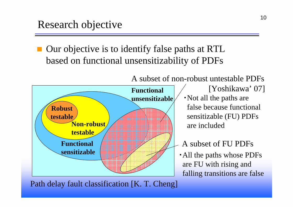
Our objective is to identify false paths at RTLbased on functional unsensitizability of PDFs
Robusttestable
Non-robusttestable
Functionalsensitizable
Functionalunsensitizable
A subset of non-robust untestable PDFs[Yoshikawa’ 07]
・Not all the paths are false because functionalsensitizable (FU) PDFsare included
Path delay fault classification [K. T. Cheng]
A subset of FU PDFs・All the paths whose PDFs
are FU with rising andfalling transitions are false
11Target RTL circuit
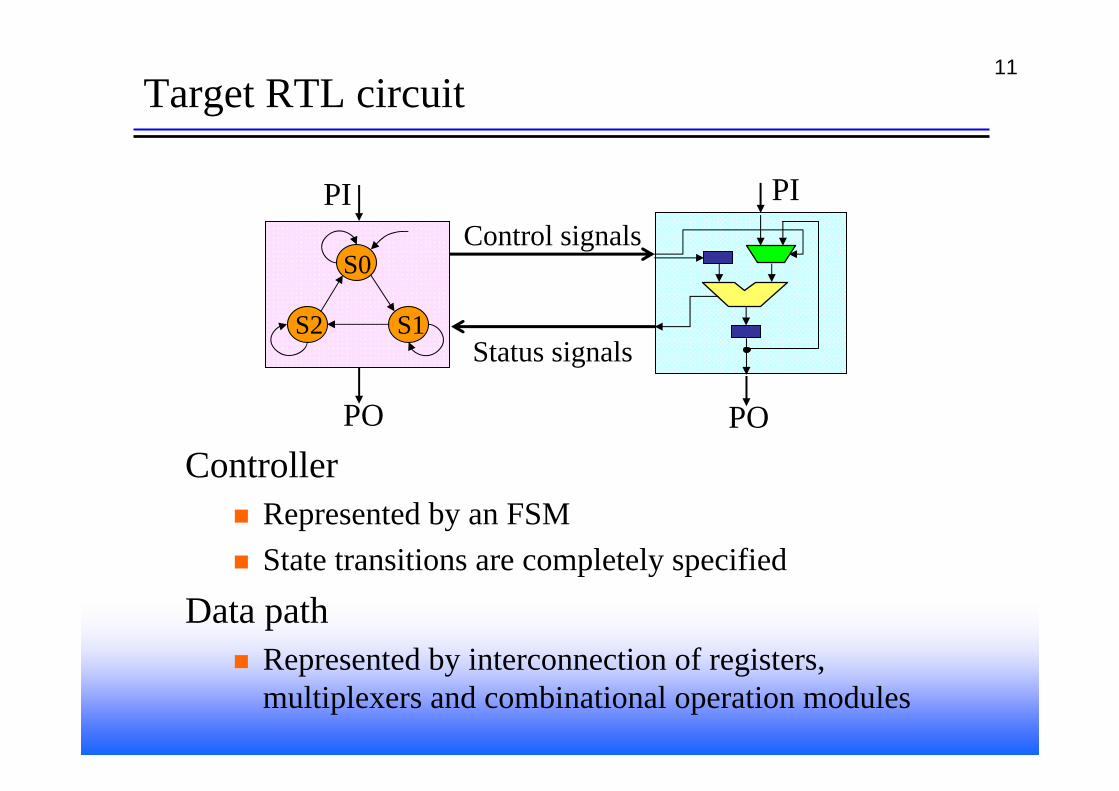
ControllerRepresented by an FSMState transitions are completely specified
Data pathRepresented by interconnection of registers, multiplexers and combinational operation modules
S0
S1S2
PI
PO
Control signals
Status signals
PI
PO
12RTL path
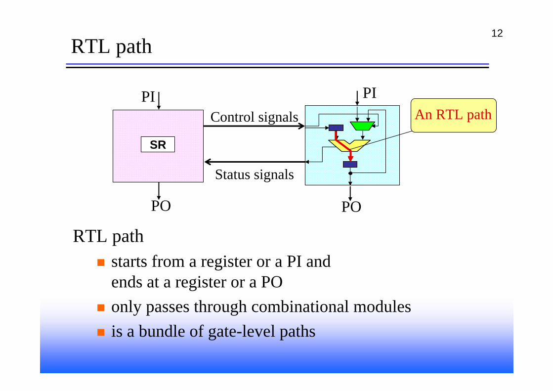
RTL pathstarts from a register or a PI and ends at a register or a POonly passes through combinational modulesis a bundle of gate-level paths
PI
PO
Control signals
Status signals
PI
PO
SR
An RTL path
13RTL functional unsensitizable (RTL-FU) path
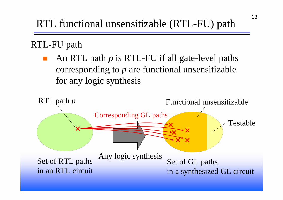
RTL-FU pathAn RTL path p is RTL-FU if all gate-level paths corresponding to p are functional unsensitizablefor any logic synthesis
Set of RTL pathsin an RTL circuit
Any logic synthesis
RTL path p
Set of GL pathsin a synthesized GL circuit
Functional unsensitizable
TestableCorresponding GL paths
14Logic synthesis
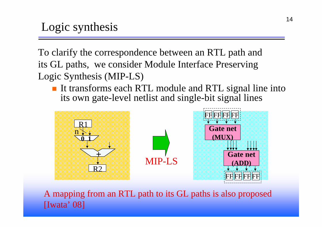
To clarify the correspondence between an RTL path andits GL paths, we consider Module Interface PreservingLogic Synthesis (MIP-LS)
It transforms each RTL module and RTL signal line into its own gate-level netlist and single-bit signal lines
0 1
R1
R2
+
n
MIP-LS
FF FF FF FF
FF FF FF FF
Gate net(MUX)
Gate net(ADD)
A mapping from an RTL path to its GL paths is also proposed[Iwata’ 08]
15Strategy for RTL-FU path identification
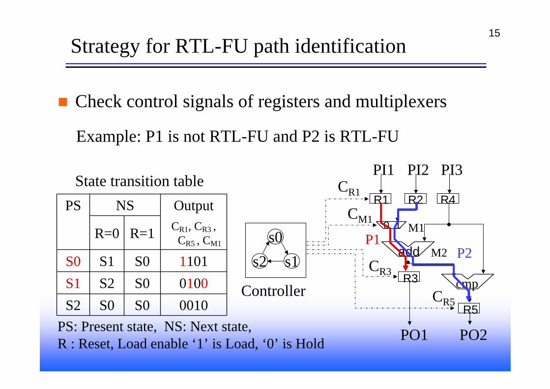
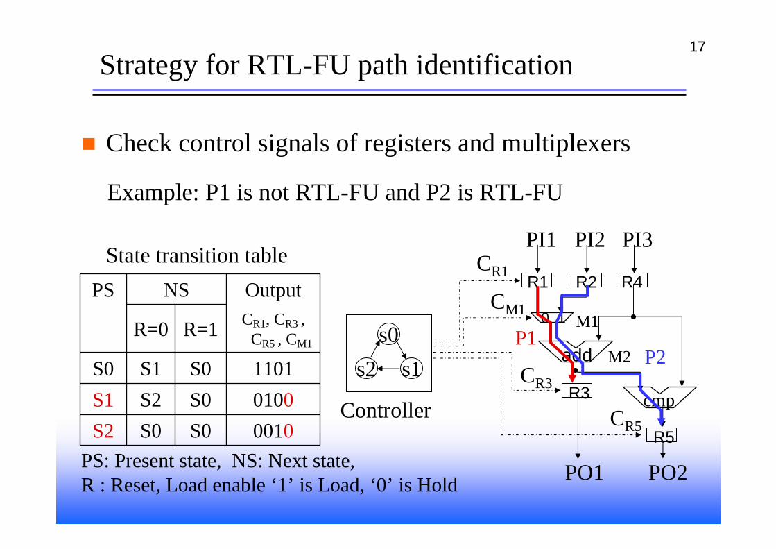
Check control signals of registers and multiplexers
s0s1s2
Controller
0 1
R1
R3
add
R2 R4CR1
CM1
PI1 PI2
M1
CR3
M2
PI3
cmp
R5CR5
PO1 PO2PS: Present state, NS: Next state,R : Reset, Load enable ‘1’ is Load, ‘0’ is Hold
PS NS Output
R=0 R=1 CR1, CR3 , CR5 , CM1
S0 S1 S0 1101S1 S2 S0 0100S2 S0 S0 0010
State transition table
P1P2
Example: P1 is not RTL-FU and P2 is RTL-FU
16Strategy for RTL-FU path identification
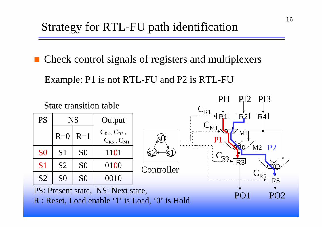
Check control signals of registers and multiplexers
s0s1s2
Controller
0 1
R1
R3
add
R2 R4CR1
CM1
PI1 PI2
M1
CR3
M2
PI3
cmp
R5CR5
PO1 PO2PS: Present state, NS: Next state,R : Reset, Load enable ‘1’ is Load, ‘0’ is Hold
PS NS Output
R=0 R=1 CR1, CR3 , CR5 , CM1
S0 S1 S0 1101S1 S2 S0 0100S2 S0 S0 0010
State transition table
P1P2
Example: P1 is not RTL-FU and P2 is RTL-FU
17Strategy for RTL-FU path identification
Check control signals of registers and multiplexers
s0s1s2
Controller
0 1
R1
R3
add
R2 R4CR1
CM1
PI1 PI2
M1
CR3
M2
PI3
cmp
R5CR5
PO1 PO2PS: Present state, NS: Next state,R : Reset, Load enable ‘1’ is Load, ‘0’ is Hold
PS NS Output
R=0 R=1 CR1, CR3 , CR5 , CM1
S0 S1 S0 1101S1 S2 S0 0100S2 S0 S0 0010
State transition table
P1P2
Example: P1 is not RTL-FU and P2 is RTL-FU

18Strategy for RTL-FU path identification
Check control signals of registers and multiplexers
s0s1s2
Controller
0 1
R1
R3
add
R2 R4CR1
CM1
PI1 PI2
M1
CR3
M2
PI3
cmp
R5CR5
PO1 PO2PS: Present state, NS: Next state,R : Reset, Load enable ‘1’ is Load, ‘0’ is Hold
PS NS Output
R=0 R=1 CR1, CR3 , CR5 , CM1
S0 S1 S0 1101S1 S2 S0 0100S2 S0 S0 0010
State transition table
P1P2
Example: P1 is not RTL-FU and P2 is RTL-FU
19
0 1
R1
R2+
(H, H, * )( *, *, * )
( *, *,* )
n0 1
R1
R2+
(*, L, * )( *, 1, 1 )
( *, *, * )
0 1
R1
R2+
(*, L, * )(*, *, 0 )
(*, H, H )
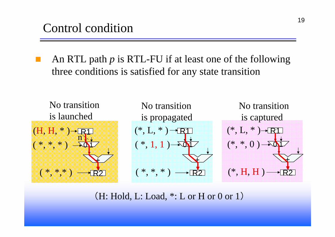
No transitionis launched
No transitionis propagated
No transitionis captured
(H: Hold, L: Load, *: L or H or 0 or 1)
Control condition
An RTL path p is RTL-FU if at least one of the following three conditions is satisfied for any state transition
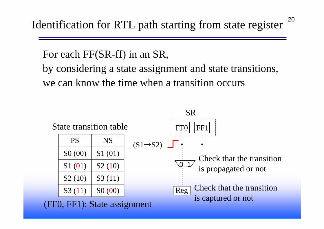
20Identification for RTL path starting from state register
For each FF(SR-ff) in an SR,by considering a state assignment and state transitions,we can know the time when a transition occurs
PS NS
S0 (00) S1 (01)S1 (01) S2 (10)S2 (10) S3 (11)S3 (11) S0 (00)
FF0
SR
State transition table
Reg
(S1→S2)
Check that the transitionis captured or not
FF1
0 1Check that the transitionis propagated or not
(FF0, FF1): State assignment
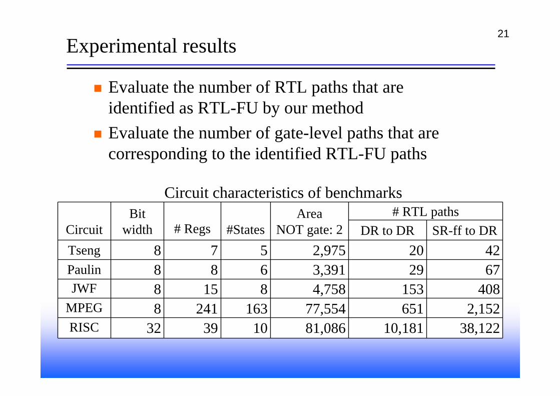
21Experimental results
Evaluate the number of RTL paths that are identified as RTL-FU by our methodEvaluate the number of gate-level paths that arecorresponding to the identified RTL-FU paths
RTLベンチマークの回路特性Circuit
Bit width # Regs #States
AreaNOT gate: 2
# RTL pathsDR to DR SR-ff to DR
Tseng 8 7 5 2,975 20 42Paulin 8 8 6 3,391 29 67JWF 8 15 8 4,758 153 408
MPEG 8 241 163 77,554 651 2,152RISC 32 39 10 81,086 10,181 38,122
Circuit characteristics of benchmarks
22
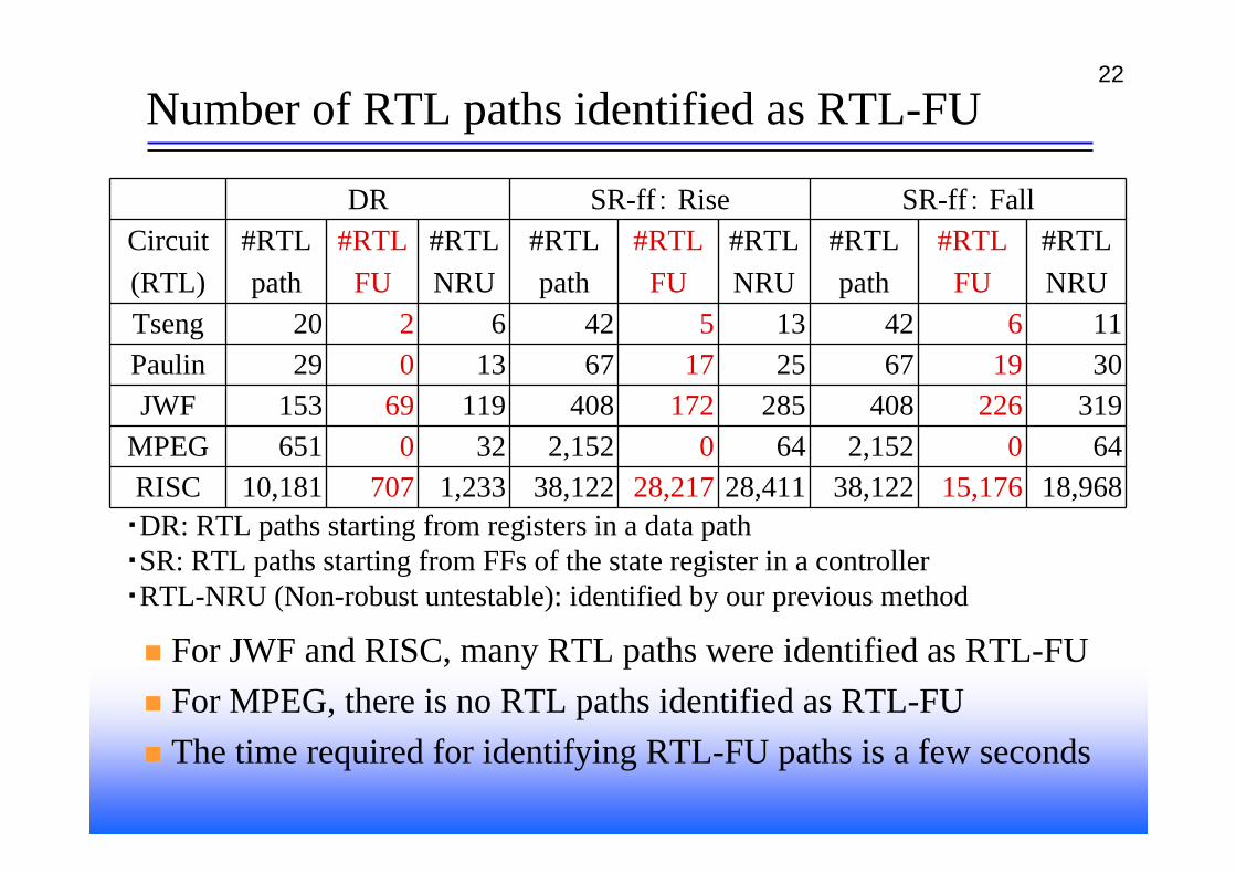
Number of RTL paths identified as RTL-FU
DR SR-ff: Rise SR-ff: FallCircuit(RTL)
#RTLpath
#RTLFU
#RTLNRU
#RTLpath
#RTLFU
#RTLNRU
#RTLpath
#RTLFU
#RTLNRU
Tseng 20 2 6 42 5 13 42 6 11Paulin 29 0 13 67 17 25 67 19 30JWF 153 69 119 408 172 285 408 226 319
MPEG 651 0 32 2,152 0 64 2,152 0 64RISC 10,181 707 1,233 38,122 28,217 28,411 38,122 15,176 18,968
For JWF and RISC, many RTL paths were identified as RTL-FUFor MPEG, there is no RTL paths identified as RTL-FUThe time required for identifying RTL-FU paths is a few seconds
・DR: RTL paths starting from registers in a data path・SR: RTL paths starting from FFs of the state register in a controller・RTL-NRU (Non-robust untestable): identified by our previous method
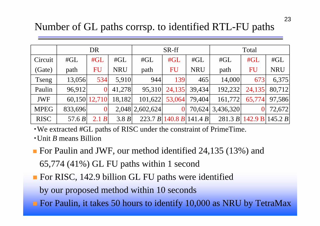
23Number of GL paths corrsp. to identified RTL-FU paths
DR SR-ff TotalCircuit(Gate)
#GLpath
#GLFU
#GLNRU
#GLpath
#GLFU
#GLNRU
#GLpath
#GLFU
#GLNRU
Tseng 13,056 534 5,910 944 139 465 14,000 673 6,375Paulin 96,912 0 41,278 95,310 24,135 39,434 192,232 24,135 80,712JWF 60,150 12,710 18,182 101,622 53,064 79,404 161,772 65,774 97,586
MPEG 833,696 0 2,048 2,602,624 0 70,624 3,436,320 0 72,672RISC 57.6 B 2.1 B 3.8 B 223.7 B 140.8 B 141.4 B 281.3 B 142.9 B 145.2 B
For Paulin and JWF, our method identified 24,135 (13%) and65,774 (41%) GL FU paths within 1 secondFor RISC, 142.9 billion GL FU paths were identifiedby our proposed method within 10 secondsFor Paulin, it takes 50 hours to identify 10,000 as NRU by TetraMax
・We extracted #GL paths of RISC under the constraint of PrimeTime.・Unit B means Billion
24Conclusion
We have proposed a method for identifyingfunctional unsensitizable paths using RTL information
The identified paths are false pathsThe time required for identification is much faster than GL approachesThe information of the identified false paths can be usedin order to reduce over-testing, andarea and performance optimization during logic synthesis
25Condition of RTL-FU path
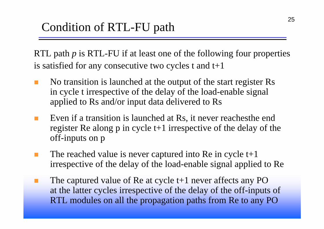
RTL path p is RTL-FU if at least one of the following four propertiesis satisfied for any consecutive two cycles t and t+1
No transition is launched at the output of the start register Rsin cycle t irrespective of the delay of the load-enable signal applied to Rs and/or input data delivered to Rs
Even if a transition is launched at Rs, it never reachesthe end register Re along p in cycle t+1 irrespective of the delay of the off-inputs on p
The reached value is never captured into Re in cycle t+1 irrespective of the delay of the load-enable signal applied to Re
The captured value of Re at cycle t+1 never affects any POat the latter cycles irrespective of the delay of the off-inputs of RTL modules on all the propagation paths from Re to any PO