Embed Size (px)
DESCRIPTION
cardio
Citation preview
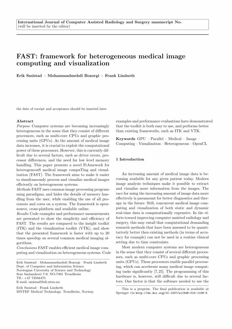
International Journal of Computer Assisted Radiology and Surgery manuscript No.(will be inserted by the editor)
FAST: framework for heterogeneous medical imagecomputing and visualization
Erik Smistad · Mohammadmehdi Bozorgi · Frank Lindseth
the date of receipt and acceptance should be inserted later
Abstract
Purpose Computer systems are becoming increasingly
heterogeneous in the sense that they consist of different
processors, such as multi-core CPUs and graphic pro-
cessing units (GPUs). As the amount of medical image
data increases, it is crucial to exploit the computational
power of these processors. However, this is currently dif-
ficult due to several factors, such as driver errors, pro-
cessor differences, and the need for low level memory
handling. This paper presents a novel FrAmework for
heterogeneouS medical image compuTing and visual-
ization (FAST). The framework aims to make it easier
to simultaneously process and visualize medical images
efficiently on heterogeneous systems.
Methods FAST uses common image processing program-
ming paradigms, and hides the details of memory han-
dling from the user, while enabling the use of all pro-
cessors and cores on a system. The framework is open-
source, cross-platform and available online.
Results Code examples and performance measurements
are presented to show the simplicity and efficiency of
FAST. The results are compared to the insight toolkit
(ITK) and the visualization toolkit (VTK), and show
that the presented framework is faster with up to 20
times speedup on several common medical imaging al-
gorithms.
Conclusions FAST enables efficient medical image com-
puting and visualization on heterogeneous systems. Code
Erik Smistad · Mohammadmehdi Bozorgi · Frank LindsethDept. of Computer and Information ScienceNorwegian University of Science and TechnologySem Saelandsvei 7-9, NO-7491 TrondheimTlf.: +47 73594475E-mail: [email protected]
Erik Smistad · Frank LindsethSINTEF Medical Technology. Trondheim, Norway.
examples and performance evaluations have demonstrated
that the toolkit is both easy to use, and performs better
than existing frameworks, such as ITK and VTK.
Keywords GPU · Parallel · Medical · Image ·Computing · Visualization · Heterogeneous · OpenCL
1 Introduction
An increasing amount of medical image data is be-
coming available for any given patient today. Modern
image analysis techniques make it possible to extract
and visualize more information from the images. The
race for using the increasing amount of image data more
effectively is paramount for better diagnostics and ther-
apy in the future. Still, concurrent medical image com-
puting and visualization of both static and dynamic
real-time data is computationally expensive. In the ef-
forts toward improving computer assisted radiology and
surgery, this may entail that computational demanding
research methods that have been assessed to be quanti-
tatively better then existing methods (in terms of accu-
racy for example) can not be used in a routine clinical
setting due to time constraints.
Most modern computer systems are heterogeneous
in the sense that they consist of several different proces-
sors, such as multi-core CPUs and graphic processing
units (GPUs). These processors enable parallel process-
ing, which can accelerate many medical image comput-
ing tasks significantly [7,25]. The programming of this
hardware is, however, still difficult due to several fac-
tors. One factor is that the software needed to use the
This is a preprint. The final publication is available atSpringer via http://dx.doi.org/10.1007/s11548-015-1158-5
2 Erik Smistad et al.
hardware, such as GPU drivers and compilers, may con-
tain errors which are hard to debug. Also, the different
manufacturers may have interpreted the standards dif-
ferently. This forces programmers to do more debugging
and testing. Since the programmer can not change pro-
prietary software such as GPU drivers, the programmer
may even have to write separate code for different hard-
ware manufacturers and software versions. The result
is increased software development overhead and frag-
mented source code.
GPUs were originally programmed using shaders in-
tended for graphics rendering. Newer frameworks, such
as CUDA [18], enable general-purpose programming of
GPUs. The open computing language (OpenCL) [29]
is an open standard for parallel programming of het-erogeneous systems. OpenCL enables parallel program-
ming of different processors such as multi-core CPUs
and GPUs. These GPU programming tools expose the
programmer to several hardware details. For instance,
most GPUs have their own memory that is separate
from the computer’s main memory. This memory is of-
ten divided into several different memory spaces such
as global, texture and constant memory [19]. Thus, the
programmer has to explicitly move data between the
different memories during execution.
In this article, we propose a framework called FAST
(FrAmework for heterogeneouS medical image compuT-
ing and visualization). This framework aims to make
it easier to do efficient processing and visualization of
medical images on heterogeneous systems. The frame-
work is open-source and available online. FAST is also
cross-platform, supporting Windows, Mac OS X and
Linux. The authors believe that in order to achieve sat-isfactory performance in the more computational de-
manding medical applications, the framework has to
cover the entire pipeline from reading and streaming
data to visualizing the result on the screen. Thus, the
framework currently includes methods for:
– Reading, writing and streaming image data in dif-
ferent formats.
– Image processing algorithms such as filtering, seg-
mentation and registration.
– Surface mesh extraction and rendering.
– Multi-volume and slice rendering.
The framework aims to be easy to use by utilizing com-
mon programming paradigms from popular toolkits,
such as the insight toolkit (ITK) and the visualization
toolkit (VTK), and hiding the details of memory han-
dling from the user. Also, the framework has many tests
and benchmarks which enable the user to make sure
http://github.com/smistad/FAST/
that all the hardware and software are working prop-
erly, and gives the performance and accuracy necessary
for a whole range of medical image processing appli-
cations. We acknowledge that there exist many medi-
cal image computing algorithms created using ITK and
VTK. The framework therefore supports interoperabil-
ity with these frameworks, such that image data can be
shared and pipelines from FAST, ITK and VTK can
be linked. This may ease the integration of FAST into
existing applications.
1.1 Related work
ITK [9,10] and VTK [21,12] are two of the most com-
monly used frameworks for medical image analysis and
visualization. ITK contains several image processing al-
gorithms used in the medical domain, while VTK is
mostly used for visualization. Several of the image pro-
cessing filters in ITK and VTK support multi-threading
for execution on multi-core CPUs. In this multi-thread-
ing model, the input image is split among a set of
threads. Each subimage is processed individually and
the result is stitched together. These frameworks were
not initially created with support for GPU acceleration,
except GPU-based rendering. However, extensions have
been proposed to enable such support [2,11]. The cur-
rent version of ITK (4.6) includes GPU implementa-
tions of some algorithms such as thresholding, smooth-
ing and optical flow registration. However, these are
implemented as separate modules which are only avail-
able if compiled with a specific flag.
The open computer vision library (OpenCV) [20]
is another popular image processing and visualizationframework. However, this framework focus primarily on
2D image processing and lack several features that are
important in the medical imaging domain such as 3D
image processing, medical image formats and surface
extraction. Still, OpenCV was designed for computa-
tional efficiency and with a strong focus on real-time
applications. Several algorithms in OpenCV are imple-
mented for the GPU using OpenCL.
While these frameworks provide accelerated process-
ing more as an extension and as an optional feature,
the FAST framework presented in this article has been
designed with heterogeneous accelerated processing in
mind from the start and it is part of the core of the
framework. We believe this will result in a framework
that is faster and easier to use.
MeVisLab [13,15] is a software which focus on rapid
prototyping of medical image software using a visual
programming interface. It also supports integration with
ITK and VTK and has support for multi-threading.
FAST on the other hand, focus on high performance
FAST: framework for heterogeneous medical image computing and visualization 3
Hardware – GPUs and CPUs
OpenCL
Eigen
Data (2.2) Importers/Exporters (2.3) Streamers (2.4)
Algorithms (2.5) Visualization (2.6)
Drivers
Tests (2.7) Benchmarks (2.8)
OpenGL
Qt
Application
Fra
mew
ork
core
Libr
arie
sBoost GLEW
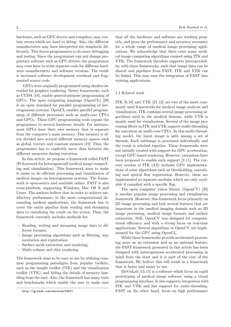
Fig. 1 Block diagram of the framework. The numbers indi-cate which section describes the different parts of the frame-work.
heterogeneous medical image computing and visualiza-
tion and has currently no visual programming interface.
One framework that aims to aid the development of
image processing algorithms for different GPUs is the
Heterogeneous Image Processing Acceleration Frame-
work (HIPAcc) [14]. However, HIPAcc focus on the de-sign of image processing algorithms and does not in-
clude visualization and registration.
1.2 Outline
The next section describes the details of the framework.
The result section presents code examples and perfor-
mance benchmarks of common medical image comput-
ing pipelines on different systems. Finally, a discussion
and conclusion is presented.
2 Methodology
The FAST framework consists of five main layers, as
illustrated in Fig. 1. The bottom layer is the actual
hardware, i.e. the CPUs and GPUs. The second layer
are the drivers for this hardware, which are provided by
the hardware manufacturers. Next is the library layer,
which consists of several libraries that are needed in the
framework. The libraries in this layer are:
– Open Computing Library (OpenCL) - An open
standard for parallel programming on heterogeneous
systems, including multi-core CPUs, GPUs, and FP-
GAs. It is supported by most processor manufactur-
ers including AMD, NVIDIA and Intel.
– Open Graphics Library (OpenGL) - A cross-
platform library for visualization.
– GL Extension Wrangler (GLEW) - A library
for handling OpenGL extensions.
– Eigen - A fast cross-platform linear algebra library.
– Qt - A cross-platform graphical user interface (GUI)
toolkit.
– Boost - A C++ utility library.
The next layer is the core of the framework, which is
split into several groups:
– Data (2.2) - Objects for data (both static and dy-
namic) such as images and meshes, which enables
the synchronized processing of such data on a set of
heterogeneous devices.
– Importers/Exporters (2.3) - Data import and
export objects for different formats such as MetaIm-
age (.mhd), raw, ITK and VTK.
– Streamers (2.4) - Objects that enable streaming
of data.
– Algorithms (2.5) - A set of commonly used filter-
ing, segmentation and registration algorithms.
– Visualization (2.6) - A set of renderers such as
image, volume, slice and mesh renderers.
– Tests (2.7) - A set of tests for the framework which
ensures that all parts of the framework are working
properly.
– Benchmarks (2.8) - Mechanisms for measuring,
assimilating and reporting the performance of all
operations in the framework.
The last layer is the application layer. The frame-
work may be both a stand-alone application, which en-
ables benchmarking and tests of a heterogeneous sys-
tem, and an external library for other medical image
computing applications.
The rest of this section will describe each part of
the framework in more detail, but first the execution
pipeline of the framework is described.
2.1 The execution pipeline
FAST uses a demand-driven execution pipeline similar
to what is used in ITK and VTK. This entails that
each processing step is first linked together to form a
pipeline, that is not executed until some object calls the
update method. This can be done in two ways:
– Explicitly by calling the update method on an ob-
ject in the pipeline.
4 Erik Smistad et al.
– Implicitly by a renderer which calls update on its
input connections several times per second.
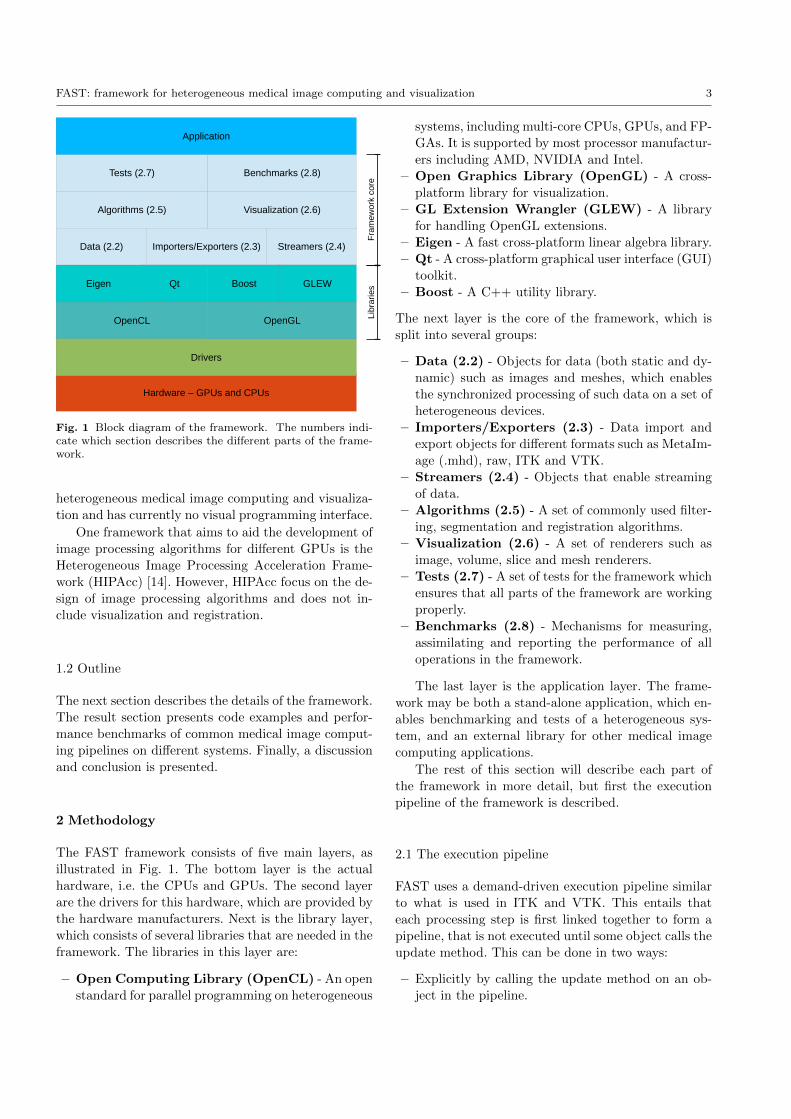
The pipeline consists of process objects, which extend
the abstract base class ProcessObject . A process object
is an object that performs processing and may have
zero, one or several parent process objects. Most pro-
cess objects produce data objects which extend the ab-
stract base class DataObject . Similar to the newest ver-
sion of VTK (version 6), FAST uses a pipeline where
the data objects are not explicitly part of the pipeline.
Fig. 2 illustrates a simple pipeline with these two types
of objects and how they are connected.
Data importer
Data object
Processing
Data exporter
Data object
Rendering
Fig. 2 A simple pipeline with process (blue/bright) and dataobjects (orange/dark). The arrows indicate how the objectsare connected.
Data objects have an internal timestamp. The times-
tamp is always updated when the data is changed. Each
process object has a list of timestamps for each connec-
tion. These timestamps represent which version of the
data objects were used the last time the process ob-
ject was executed. In addition, each process object has
a flag indicating whether it has been modified or not.
This could be a parameter or input change.
When the update method is called on a process ob-
ject, it will first call update on all its parent objects.
Thus update will be called on all objects backwards in
the pipeline until a process object with no input connec-
tions is encountered (e.g. an importer object). A process
object will re-execute by calling its execute method, if it
is modified or one of its input connections have changed
timestamps. Thus each process object will implement
its own execute method while the update method is
the same for each process object.
2.2 Data management
Throughout this article, we will use the OpenCL ter-
minology and refer to a processor with its memory as a
device, and the main CPU as the host.
Host (CPU)
Memory
OpenCL Device (CPU/GPU)
Memory
OpenCL Device (CPU/GPU)
Memory
OpenCL Device (CPU/GPU)
Memory
Pointers to where the data is stored
Data object
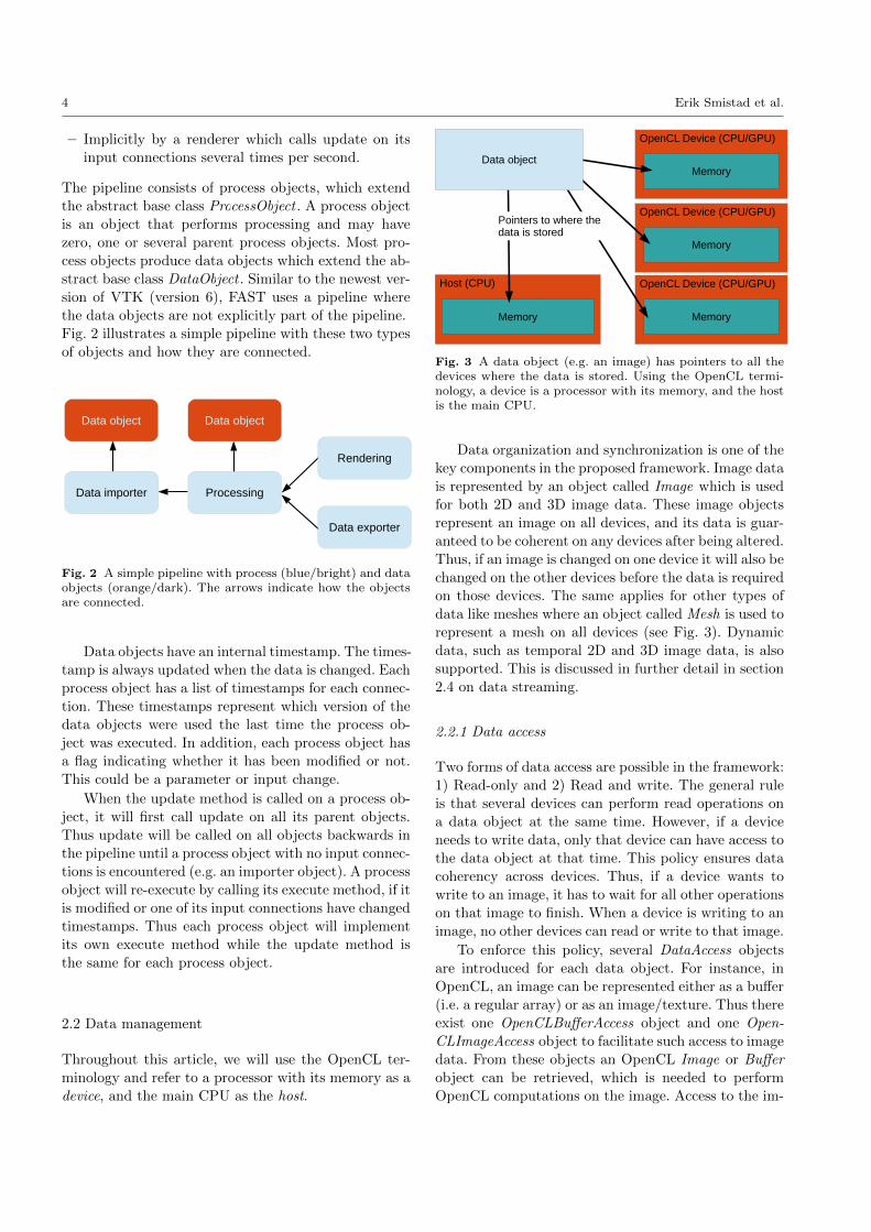
Fig. 3 A data object (e.g. an image) has pointers to all thedevices where the data is stored. Using the OpenCL termi-nology, a device is a processor with its memory, and the hostis the main CPU.
Data organization and synchronization is one of the
key components in the proposed framework. Image data
is represented by an object called Image which is used
for both 2D and 3D image data. These image objects
represent an image on all devices, and its data is guar-
anteed to be coherent on any devices after being altered.
Thus, if an image is changed on one device it will also be
changed on the other devices before the data is required
on those devices. The same applies for other types of
data like meshes where an object called Mesh is used to
represent a mesh on all devices (see Fig. 3). Dynamic
data, such as temporal 2D and 3D image data, is also
supported. This is discussed in further detail in section
2.4 on data streaming.
2.2.1 Data access
Two forms of data access are possible in the framework:
1) Read-only and 2) Read and write. The general rule
is that several devices can perform read operations on
a data object at the same time. However, if a device
needs to write data, only that device can have access to
the data object at that time. This policy ensures data
coherency across devices. Thus, if a device wants to
write to an image, it has to wait for all other operations
on that image to finish. When a device is writing to an
image, no other devices can read or write to that image.
To enforce this policy, several DataAccess objects
are introduced for each data object. For instance, in
OpenCL, an image can be represented either as a buffer
(i.e. a regular array) or as an image/texture. Thus there
exist one OpenCLBufferAccess object and one Open-
CLImageAccess object to facilitate such access to image
data. From these objects an OpenCL Image or Buffer
object can be retrieved, which is needed to perform
OpenCL computations on the image. Access to the im-
FAST: framework for heterogeneous medical image computing and visualization 5
age from the main memory can also be requested for
doing processing on the CPU using C++. The DataAc-
cess objects also have methods for releasing the access,
thus enabling other devices to perform write operations
on the image. The access will also be released in the de-
structor of this object to avoid deadlocks. When the
access is released, the OpenCL Image/Buffer object
pointer is invalidated to ensure that the program can
no longer manipulate the data. However, this does not
delete the actual data on the device. When write access
to an object is requested, the framework will check that
any previous access objects have been released.
2.2.2 Data change
Every time data is changed on a device, the change
should be reflected on the other devices as well. How-
ever, this doesn’t have to be done immediately. Updat-
ing the data can be done the next time the data is
requested on another device. This is often referred to
as lazy loading. The benefit of lazy loading is that the
number of data transfers can be reduced. However, the
drawback is that there will be a transfer cost the next
time the data is requested on a device which doesn’t
have the updated data.
Thus, each data object has a set of flags indicating
whether the data (in the form of OpenCL buffers, im-
ages and C++ pointers) is up to date for each device.
When one device has changed some data, these are set
to false for all devices except the device in which the
change was performed. Next time the data is requested
on a device, the flag is checked and if it is false, a data
transfer will start and the flag will be set to true for
that device.
2.2.3 Data removal
The amount of memory available on a system as well as
on graphic cards are limited, and may not be enough
when working on large datasets. Thus it is crucial to
remove data that is not needed anymore. Data may be
deleted explicitly by the programmer, however, this is
a burden for the programmer and may easily be for-
gotten. After the entire pipeline has been defined by
the programmer it is known which process objects need
which data objects as input. Thus it is possible to delete
a data object after all the process objects that use this
data object have finished execution. This requires each
process object to retain and release the data objects
when they are defined as input and when the process
object is finished using it. To facilitate this, each data
object has a reference counter and when it reaches zero,
the data is deleted.
2.2.4 Data types
Medical images are represented in different formats.
Some common examples are: Ultrasound (unsigned 8
bit integer), CT (signed/unsigned 16 bit integer) and
MR (unsigned 16 bit integer). The framework currently
supports the following data formats for images:
– TYPE FLOAT - 32 bit floating point number
– TYPE UINT8 - 8 bit unsigned integer
– TYPE INT8 - 8 bit signed integer
– TYPE UINT16 - 16 bit unsigned integer
– TYPE INT16 - 16 bit signed integer
An image can also have multiple channels, or compo-
nents, and currently 1-4 channels are supported.
2.3 Data import and export
Data can be imported to and exported from the frame-
work in several different forms such as:
– MetaImage file (.mhd, .raw and .zraw)
– Image file (.jpg, .png etc.)
– ITK image object
– VTK image object
– VTK file (.vtk)
In the future, the framework will also support com-mon data formats such as DICOM [16] and NIfTI [17].
2.4 Data streaming
Streamers are process objects that provide access to dy-
namic data. This can for instance be real-time images
from an ultrasound probe or a series of images stored
on disk. The output of streamer objects is a Dynam-
icData object, which has a method for retrieving the
current frame in the stream. The DynamicData objects
can contain one of several types of data such as images
or meshes. The streamers read data into the Dynamic-
Data object in a separate thread so that processing and
data streaming can be performed concurrently. Stream-
ers can use one of three different streaming modes:
– STREAMING MODE NEWEST FRAME ONLY
This will only keep the newest frame in the Dynam-
icData object.
– STREAMING MODE PROCESS ALL FRAMES
This will keep all frames in the DynamicData ob-
ject, but will remove the frame from the object after
it has been processed.
– STREAMING MODE STORE ALL FRAMES
This will store all frames in the DynamicData ob-
ject.

6 Erik Smistad et al.
For the second of these streaming modes it is also im-
portant to limit the size of the dynamic data buffer so
that the streaming does not use up all memory. With
this mode it is therefore possible to set the maximum
size of the dynamic data buffer. A producer-consumer
model is used to synchronize the use of the data.
The data and process objects are designed so that it
is easy to accept both static and dynamic data as input
and output to an algorithm.
2.5 Algorithms
Algorithms are implemented in the framework as pro-
cess objects and thus have to override the execute method.
Currently only a few filtering, segmentation and reg-
istration algorithms have been implemented such as
Gaussian smoothing, seeded region growing [1], thresh-
olding, skeletonization [8], iterative closest point [3] and
surface extraction (marching cubes) [23]. All algorithms
support parallel processing on CPUs and GPUs. In the
near future, we plan to implement and integrate sev-
eral other algorithms such as level set segmentation,
Kalman filter object tracking [28], gradient vector flow
[22,27] and tube detection filters [24,26].
2.6 Visualization
2.6.1 Graphical user interface and rendering
Qt is used in FAST as the graphical user interface. Qt
is cross-platform, supports multi-threading, direct ren-
dering from OpenGL and event handling of keyboardand mouse input. A visualization window in the FAST
framework can have multiple views, and each view can
have multiple renderers. Windows are implemented us-
ing Qt’s QWidget class, while the View extends the
QGLWidget, which is a widget that may be rendered
to by OpenGL. The FAST renderers do the actual ren-
dering. These renderers and the event handling is exe-
cuted in one thread, while the pipeline is run in another
thread. This enables concurrent visualization, camera
movement and pipeline execution. Five different types
of renderers are currently available in FAST:
– Image renderer - For displaying 2D images.
– Slice renderer - Extracts and displays an image from
a volume in an arbitrary plane using trilinear inter-
polation.
– Mesh renderer - Renders a mesh.
– Volume renderer - Creates an image of a volume
using ray casting [4].
– Point renderer - Renders a list of points.
Root A
Image A Image B
Mesh A Mesh B
Root B
Image C
TIA TIB TIC
TMBTMA
Fig. 4 An example of a scene graph. Images A and B areregistered because they share a root node. Image C is notregistered to any other data. Each edge between the nodeshas a transformation object. This transformation determineshow data is positioned relative to other nodes. Meshes A andB are dependent on image A. Thus, moving image A will alsomove these meshes.
2.6.2 Scene graph
Correct placement of images and geometry in the visu-
alization scene is important. FAST uses a scene graph
for this purpose. In this directed graph, each data object
has a node. All data nodes are connected to a parent
node, which can be another data node or a root node.
Each edge between the nodes has a transformation ob-
ject. This transformation determines how data is posi-
tioned relative to other nodes. Fig. 4 shows an example
of a scene graph with three images and two meshes. The
images A and B share a root node, and are therefore
registered. Image C is not registered to any other data.
Image A is placed in the visualization scene by applying
the transformation TIA to the image. Similarly, image
B uses the transformation TIB . Since these images areregistered, the corresponding voxel position in image B
of a voxel position in image A can be determined by
first applying the transformation TIA, and then the in-
verse transformation of image B T−1IB . The meshes A
and B are related to image A. These meshes may for
instance be the result of a segmentation of image A.
Mesh A is placed in the visualization scene by first ap-
plying the transformation from the mesh to image A
TMA, and then the transformation from image A to the
root node TIA. Thus, if image A is moved in the scene,
the meshes A and B are also moved.
When an image or mesh is created, a corresponding
data node is created in the scene graph and connected
to a root node. However, if the data is created from
another data object, it is connected to the data node
of that data object instead. For instance, the surface
extraction algorithm will connect the resulting mesh
to the image used to create the mesh. A visualization
of an image and a segmented surface mesh using the
scene graph is illustrated in Fig. 6. When importing
FAST: framework for heterogeneous medical image computing and visualization 7
a MetaImage, any transformation information such as
translation and rotation is read from the MetaImage
file (.mhd) and put in the scene graph.
2.7 Tests
As much as possible of the framework should be covered
by unit and system tests. This enables a user to ensure
that the framework is working correctly on the user’s
current software and hardware configuration. The au-
thors know by experience that new drivers, compilers
and libraries can introduce errors that may stop the
framework from working properly. These tests enable
a user to quickly detect these problems. The tests are
written using the Catch C++ testing framework [5].
Realistic test data is needed to test the framework prop-
erly, and is therefore provided for download.
The framework is available on the open-source com-
munity website GitHub. Each time a user contributes
to the project, three different computers will execute
all tests with the new code and verify that everything
is working. These machines use all the supported oper-
ating systems Windows, Mac OS X and Ubuntu Linux
and processors from Intel, AMD and NVIDIA. Thus,
the source code of the framework is tested continuously
on several hardware and software configurations. We
believe this is needed in order to ensure the stability of
FAST.
2.8 Benchmarks
Users may also want to test how well their current setup
performs and see how performance changes when soft-
ware and hardware changes are introduced. For this
purpose benchmarks are provided, which are tests of
different pipelines in which performance is measured
and reported.
3 Results
This section first presents some examples of how the
framework can be used. These examples are provided
to show how easy it is to set up pipelines in FAST.
Next, the performance of the framework is measured
and compared to that of ITK and VTK.
3.1 Code examples
The first example is a simple pipeline of four steps: im-
port 3D image from disk, Gaussian smoothing, surface
http://github.com/smistad/FAST/wiki/Test-data
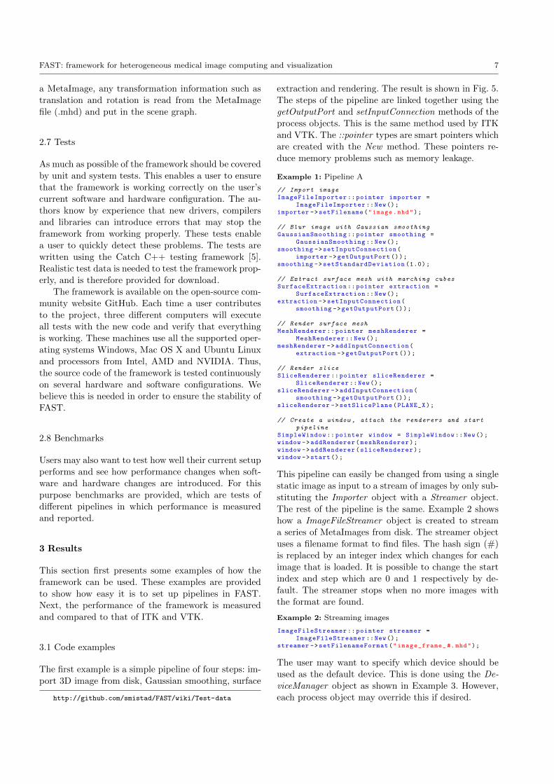
extraction and rendering. The result is shown in Fig. 5.
The steps of the pipeline are linked together using the
getOutputPort and setInputConnection methods of the
process objects. This is the same method used by ITK
and VTK. The ::pointer types are smart pointers which
are created with the New method. These pointers re-
duce memory problems such as memory leakage.
Example 1: Pipeline A
// Import imageImageFileImporter :: pointer importer =
ImageFileImporter ::New();importer ->setFilename("image.mhd");
// Blur image with Gaussian smoothingGaussianSmoothing :: pointer smoothing =
GaussianSmoothing ::New();smoothing ->setInputConnection(
importer ->getOutputPort ());smoothing ->setStandardDeviation (1.0);
// Extract surface mesh with marching cubesSurfaceExtraction :: pointer extraction =
SurfaceExtraction ::New();extraction ->setInputConnection(
smoothing ->getOutputPort ());
// Render surface meshMeshRenderer :: pointer meshRenderer =
MeshRenderer ::New();meshRenderer ->addInputConnection(
extraction ->getOutputPort ());
// Render sliceSliceRenderer :: pointer sliceRenderer =
SliceRenderer ::New();sliceRenderer ->addInputConnection(
smoothing ->getOutputPort ());sliceRenderer ->setSlicePlane(PLANE_X);
// Create a window , attach the renderers and startpipeline
SimpleWindow :: pointer window = SimpleWindow ::New();window ->addRenderer(meshRenderer);window ->addRenderer(sliceRenderer);window ->start();
This pipeline can easily be changed from using a single
static image as input to a stream of images by only sub-
stituting the Importer object with a Streamer object.
The rest of the pipeline is the same. Example 2 shows
how a ImageFileStreamer object is created to stream
a series of MetaImages from disk. The streamer object
uses a filename format to find files. The hash sign (#)
is replaced by an integer index which changes for each
image that is loaded. It is possible to change the start
index and step which are 0 and 1 respectively by de-
fault. The streamer stops when no more images with
the format are found.
Example 2: Streaming images
ImageFileStreamer :: pointer streamer =ImageFileStreamer ::New();
streamer ->setFilenameFormat("image_frame_ #.mhd");
The user may want to specify which device should be
used as the default device. This is done using the De-
viceManager object as shown in Example 3. However,
each process object may override this if desired.
8 Erik Smistad et al.
Fig. 5 Result of pipeline A in Example 1. A 3D ultrasoundimage is first smoothed. Then, surface extraction is used toextract a surface mesh from the smoothed image. Finally, aslice of the smoothed 3D image is rendered together with thesurface mesh.
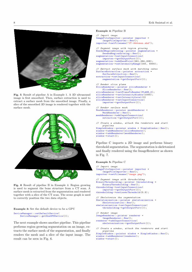
Fig. 6 Result of pipeline B in Example 4. Region growingis used to segment the bone structure from a CT scan. Asurface mesh is extracted from the segmentation and renderedtogether with a slice of the CT scan. The scene graph is usedto correctly position the two data objects.
Example 3: Set the default device to be a GPU
DeviceManager :: setDefaultDevice(DeviceManager :: getOneGPUDevice ());
The next example shows another pipeline. This pipeline
performs region growing segmentation on an image, ex-
tracts the surface mesh of the segmentation, and finally
renders the mesh and a slice of the input image. The
result can be seen in Fig. 6.
Example 4: Pipeline B
// Import imageImageFileImporter :: pointer importer =
ImageFileImporter ::New();importer ->setFilename("CT -Abdomen.mhd");
// Segment image with region growingSeededRegionGrowing :: pointer segmentation =
SeededRegionGrowing ::New();segmentation ->setInputConnection(
importer ->getOutputPort ());segmentation ->addSeedPoint (261 ,284 ,208);segmentation ->setIntensityRange (150, 5000);
// Extract surface mesh with marching cubesSurfaceExtraction :: pointer extraction =
SurfaceExtraction ::New();extraction ->setInputConnection(
segmentation ->getOutputPort ());
// Render slice planeSliceRenderer :: pointer sliceRenderer =
SliceRenderer ::New();sliceRenderer ->setPlaneToRender(PLANE_Z);sliceRenderer ->setIntensityWindow (1000);sliceRenderer ->setIntensityLevel (0)sliceRenderer ->setInputConnection(
importer ->getOutputPort ());
// Render surface meshMeshRenderer :: pointer meshRenderer =
MeshRenderer ::New();meshRenderer ->addInputConnection(
extraction ->getOutputPort ());
// Create a window , attach the renderers and startpipeline
SimpleWindow :: pointer window = SimpleWindow ::New();window ->addRenderer(sliceRenderer);window ->addRenderer(meshRenderer);window ->start();
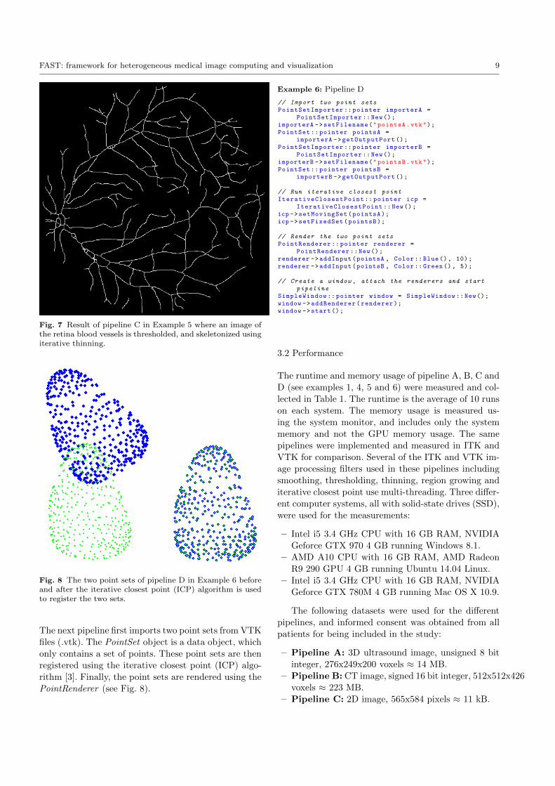
Pipeline C imports a 2D image and performs binary
threshold segmentation. The segmentation is skeletonized
and finally rendered using the ImageRenderer as shown
in Fig. 7.
Example 5: Pipeline C
// Import imageImageFileImporter :: pointer importer =
ImageFileImporter ::New();importer ->setFilename("image.png");
// Segment image with thresholdingBinaryThresholding :: pointer thresholding =
BinaryThresholding ::New();thresholding ->setInputConnection(
importer ->getOutputPort ());thresholding ->setLowerThreshold (0.5);
// Skeletonize the segmentationSkeletonization :: pointer skeletonization =
Skeletonization ::New();skeletonization ->setInputConnection(
thresholding ->getOutputPort ());
// Render imageImageRenderer :: pointer renderer =
ImageRenderer ::New();renderer ->addInputConnection(
skeletonization ->getOutputPort ());
// Create a window , attach the renderers and startpipeline
SimpleWindow :: pointer window = SimpleWindow ::New();window ->addRenderer(renderer);window ->start();
FAST: framework for heterogeneous medical image computing and visualization 9
Fig. 7 Result of pipeline C in Example 5 where an image ofthe retina blood vessels is thresholded, and skeletonized usingiterative thinning.
Fig. 8 The two point sets of pipeline D in Example 6 beforeand after the iterative closest point (ICP) algorithm is usedto register the two sets.
The next pipeline first imports two point sets from VTK
files (.vtk). The PointSet object is a data object, which
only contains a set of points. These point sets are then
registered using the iterative closest point (ICP) algo-
rithm [3]. Finally, the point sets are rendered using the
PointRenderer (see Fig. 8).
Example 6: Pipeline D
// Import two point setsPointSetImporter :: pointer importerA =
PointSetImporter ::New();importerA ->setFilename("pointsA.vtk");PointSet :: pointer pointsA =
importerA ->getOutputPort ();PointSetImporter :: pointer importerB =
PointSetImporter ::New();importerB ->setFilename("pointsB.vtk");PointSet :: pointer pointsB =
importerB ->getOutputPort ();
// Run iterative closest pointIterativeClosestPoint :: pointer icp =
IterativeClosestPoint ::New();icp ->setMovingSet(pointsA);icp ->setFixedSet(pointsB);
// Render the two point setsPointRenderer :: pointer renderer =
PointRenderer ::New();renderer ->addInput(pointsA , Color::Blue(), 10);renderer ->addInput(pointsB , Color:: Green(), 5);
// Create a window , attach the renderers and startpipeline
SimpleWindow :: pointer window = SimpleWindow ::New();window ->addRenderer(renderer);window ->start();
3.2 Performance
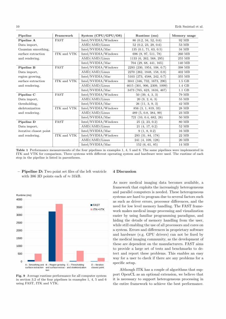
The runtime and memory usage of pipeline A, B, C and
D (see examples 1, 4, 5 and 6) were measured and col-
lected in Table 1. The runtime is the average of 10 runs
on each system. The memory usage is measured us-
ing the system monitor, and includes only the system
memory and not the GPU memory usage. The same
pipelines were implemented and measured in ITK and
VTK for comparison. Several of the ITK and VTK im-
age processing filters used in these pipelines including
smoothing, thresholding, thinning, region growing and
iterative closest point use multi-threading. Three differ-
ent computer systems, all with solid-state drives (SSD),
were used for the measurements:
– Intel i5 3.4 GHz CPU with 16 GB RAM, NVIDIA
Geforce GTX 970 4 GB running Windows 8.1.
– AMD A10 CPU with 16 GB RAM, AMD Radeon
R9 290 GPU 4 GB running Ubuntu 14.04 Linux.
– Intel i5 3.4 GHz CPU with 16 GB RAM, NVIDIA
Geforce GTX 780M 4 GB running Mac OS X 10.9.
The following datasets were used for the different
pipelines, and informed consent was obtained from all
patients for being included in the study:
– Pipeline A: 3D ultrasound image, unsigned 8 bit
integer, 276x249x200 voxels ≈ 14 MB.
– Pipeline B: CT image, signed 16 bit integer, 512x512x426
voxels ≈ 223 MB.
– Pipeline C: 2D image, 565x584 pixels ≈ 11 kB.
10 Erik Smistad et al.
Pipeline Framework System (CPU/GPU/OS) Runtime (ms) Memory usage
Pipeline A FAST Intel/NVIDIA/Windows 86 (0.2, 34, 52, 0.6) 92 MB
Data import, AMD/AMD/Linux 52 (0.2, 23, 29, 0.6) 53 MB
Gaussian smoothing, Intel/NVIDIA/Mac 135 (0.1, 71, 63, 0.5) 34 MB
surface extraction ITK and VTK Intel/NVIDIA/Windows 696 (9, 97, 511, 78) 260 MB
and rendering. AMD/AMD/Linux 1133 (6, 262, 568, 295) 255 MB
Intel/NVIDIA/Mac 704 (29, 68, 441, 165) 140 MB
Pipeline B FAST Intel/NVIDIA/Windows 2293 (230, 1954, 108, 0.7) 398 MB
Data import, AMD/AMD/Linux 2270 (262, 1848, 158, 0.8) 402 MB
region growing, Intel/NVIDIA/Mac 5103 (273, 4588, 242, 0.7) 355 MB
surface extraction ITK and VTK Intel/NVIDIA/Windows 3041 (346, 732, 1673, 290) 1.5 GB
and rendering. AMD/AMD/Linux 4615 (301, 906, 2309, 1099) 1.4 GB
Intel/NVIDIA/Mac 3473 (765, 623, 1616, 467) 1.1 GB
Pipeline C FAST Intel/NVIDIA/Windows 50 (39, 4, 3, 3) 79 MB
Data import, AMD/AMD/Linux 20 (9, 2, 6, 3) 55 MB
thresholding, Intel/NVIDIA/Mac 26 (11, 3, 9, 3) 42 MB
skeletonization ITK and VTK Intel/NVIDIA/Windows 856 (3, 1, 819, 33) 28 MB
and rendering. AMD/AMD/Linux 489 (5, 0.8, 384, 99) 23 MB
Intel/NVIDIA/Mac 721 (10, 0.4, 682, 28) 50 MB
Pipeline D FAST Intel/NVIDIA/Windows 25 (2, 23, 0.2) 80 MB
Data import, AMD/AMD/Linux 21 (4, 17, 0.2) 52 MB
iterative closest point Intel/NVIDIA/Mac 9 (1, 8, 0.2) 16 MB
and rendering. ITK and VTK Intel/NVIDIA/Windows 293 (31, 84, 178) 22 MB
AMD/AMD/Linux 241 (4, 109, 128) 20 MB
Intel/NVIDIA/Mac 152 (6, 61, 85) 14 MB
Table 1 Performance measurements of the four pipelines in examples 1, 4, 5 and 6. The same pipelines were implemented inITK and VTK for comparison. Three systems with different operating system and hardware were used. The runtime of eachstep in the pipeline is listed in parentheses.
– Pipeline D: Two point set files of the left ventricle
with 386 3D points each of ≈ 31kB.
A – Smoothing and surface extraction
B – Region growing and surface extrac-tion
C – Thresholding and skeletonization
D – Iterative closest point
0
500
1000
1500
2000
2500
3000
3500
4000
FAST
ITK+VTK
Runtime (ms)
Fig. 9 Average runtime performance for all computer systemin section 3.2 of the four pipelines in examples 1, 4, 5 and 6using FAST, ITK and VTK.
4 Discussion
As more medical imaging data becomes available, a
framework that exploits the increasingly heterogeneous
and parallel computers is needed. These heterogeneoussystems are hard to program due to several factors such
as such as driver errors, processor differences, and the
need for low level memory handling. The FAST frame-
work makes medical image processing and visualization
easier by using familiar programming paradigms, and
hiding the details of memory handling from the user,
while still enabling the use of all processors and cores on
a system. Errors and differences in proprietary software
and hardware (e.g. GPU drivers) can not be fixed by
the medical imaging community, as the development of
these are dependent on the manufacturers. FAST aims
to provide a large set of tests and benchmarks to de-
tect and report these problems. This enables an easy
way for a user to check if there are any problems for a
specific setup.
Although ITK has a couple of algorithms that sup-
port OpenCL as an optional extension, we believe that
it is necessary to support heterogeneous processing in
the entire framework to achieve the best performance.
FAST: framework for heterogeneous medical image computing and visualization 11
Data import Processing Rendering0
100
200
300
400
500
600
700
FAST
ITK+VTK
Runtime (ms)
Data import Processing Rendering0
500
1000
1500
2000
2500
3000
FAST
ITK+VTK
Runtime (ms)
Data import Processing Rendering0
100
200
300
400
500
600
700
FAST
ITK+VTK
Runtime (ms)
Data import Processing Rendering0
20
40
60
80
100
120
140
FAST
ITK+VTK
Runtime (ms)
Pipeline ASmoothing and surface extraction
Pipeline BRegion growing and surface extraction
Pipeline CThresholding and skeletonization
Pipeline DIterative closest point
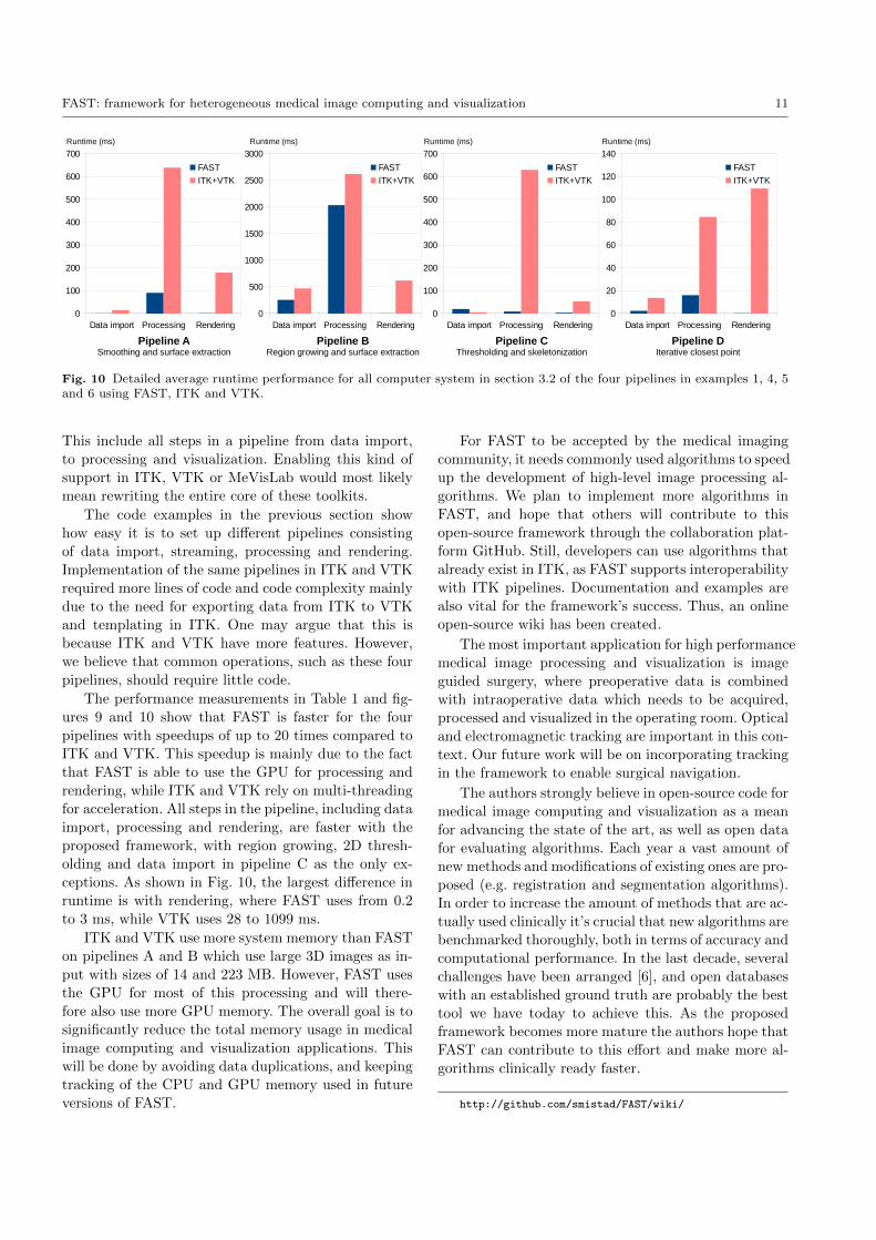
Fig. 10 Detailed average runtime performance for all computer system in section 3.2 of the four pipelines in examples 1, 4, 5and 6 using FAST, ITK and VTK.
This include all steps in a pipeline from data import,
to processing and visualization. Enabling this kind of
support in ITK, VTK or MeVisLab would most likely
mean rewriting the entire core of these toolkits.
The code examples in the previous section show
how easy it is to set up different pipelines consisting
of data import, streaming, processing and rendering.
Implementation of the same pipelines in ITK and VTK
required more lines of code and code complexity mainly
due to the need for exporting data from ITK to VTK
and templating in ITK. One may argue that this is
because ITK and VTK have more features. However,
we believe that common operations, such as these four
pipelines, should require little code.
The performance measurements in Table 1 and fig-
ures 9 and 10 show that FAST is faster for the four
pipelines with speedups of up to 20 times compared to
ITK and VTK. This speedup is mainly due to the fact
that FAST is able to use the GPU for processing and
rendering, while ITK and VTK rely on multi-threading
for acceleration. All steps in the pipeline, including data
import, processing and rendering, are faster with the
proposed framework, with region growing, 2D thresh-
olding and data import in pipeline C as the only ex-
ceptions. As shown in Fig. 10, the largest difference in
runtime is with rendering, where FAST uses from 0.2
to 3 ms, while VTK uses 28 to 1099 ms.
ITK and VTK use more system memory than FAST
on pipelines A and B which use large 3D images as in-
put with sizes of 14 and 223 MB. However, FAST uses
the GPU for most of this processing and will there-
fore also use more GPU memory. The overall goal is to
significantly reduce the total memory usage in medical
image computing and visualization applications. This
will be done by avoiding data duplications, and keeping
tracking of the CPU and GPU memory used in future
versions of FAST.
For FAST to be accepted by the medical imaging
community, it needs commonly used algorithms to speed
up the development of high-level image processing al-
gorithms. We plan to implement more algorithms in
FAST, and hope that others will contribute to this
open-source framework through the collaboration plat-
form GitHub. Still, developers can use algorithms that
already exist in ITK, as FAST supports interoperability
with ITK pipelines. Documentation and examples are
also vital for the framework’s success. Thus, an online
open-source wiki has been created.
The most important application for high performance
medical image processing and visualization is image
guided surgery, where preoperative data is combined
with intraoperative data which needs to be acquired,
processed and visualized in the operating room. Optical
and electromagnetic tracking are important in this con-
text. Our future work will be on incorporating tracking
in the framework to enable surgical navigation.
The authors strongly believe in open-source code for
medical image computing and visualization as a mean
for advancing the state of the art, as well as open data
for evaluating algorithms. Each year a vast amount of
new methods and modifications of existing ones are pro-
posed (e.g. registration and segmentation algorithms).
In order to increase the amount of methods that are ac-
tually used clinically it’s crucial that new algorithms are
benchmarked thoroughly, both in terms of accuracy and
computational performance. In the last decade, several
challenges have been arranged [6], and open databases
with an established ground truth are probably the best
tool we have today to achieve this. As the proposed
framework becomes more mature the authors hope that
FAST can contribute to this effort and make more al-
gorithms clinically ready faster.
http://github.com/smistad/FAST/wiki/
12 Erik Smistad et al.
5 Conclusion
A novel framework for efficient medical image comput-
ing and visualization has been presented. The frame-
work was built from ground up with optimal perfor-
mance on heterogeneous systems in mind. Code exam-
ples and performance evaluations have demonstrated
that the toolkit is both easy to use, and performs better
than existing frameworks, such as ITK and VTK. Built-
in benchmarking support will make additional fine-tuning
a lot easier, and produce new insight about hetero-
geneous computing in the medical domain. As more
quality and performance benchmarked functionality is
added to the framework, the authors hope that FAST
will be a valid tool for bringing more medical imaging
software into clinical practice in the years to come.
Acknowledgements This project has received funding fromthe European Union’s Seventh Framework Programme for re-search, technological development and demonstration undergrant agreement no 610425. The hardware used in this projectwas funded by the MedIm (Norwegian Research School inMedical Imaging) Travel and Research Grant.
Conflict of interest Erik Smistad, Mohammadmehdi Bozorgiand Frank Lindseth declare that they have no conflict of in-terest.
References
1. R. Adams and L. Bischof. Seeded region growing. IEEE
Transactions on Pattern Analysis and Machine Intelligence,16(6):641–647, June 1994.
2. R. Beare, D. Micevski, C. Share, L. Parkinson, P. Ward,W. Goscinski, and M. Kuiper. CITK - an architectureand examples of CUDA enabled ITK filters. pages 1–8,2011.
3. P. J. Besl and N. D. McKay. A method for registrationof 3-D shapes. IEEE Transactions on pattern analysis and
machine intelligence, 1992.4. M. Bozorgi and F. Lindseth. GPU-based multi-volume
ray casting within VTK for medical applications. Inter-
national journal of computer assisted radiology and surgery,May 2014.
5. Catch. C++ Automated Test Cases in Headers. https:
//github.com/philsquared/Catch/ - Last accessed 10. Oct2014.
6. Consortium for Open Medical Image Computing. GrandChallenges in Biomedical Image Analysis. http://
grand-challenge.org/ - Last accessed 25. Nov 2014.7. A. Eklund, P. Dufort, D. Forsberg, and S. M. Laconte.
Medical image processing on the GPU - Past, presentand future. Medical image analysis, 17(8):1073–1094, June2013.
8. R. C. Gonzalez and R. E. Woods. Digital Image Process-
ing. Pearson Prentice Hall, third edition, 2008.9. L. Ibanez and W. Schroeder. The ITK Software Guide.
Kitware, 2.4 edition, 2004.10. Kitware. Insight toolkit (ITK). http://itk.org/ - Last
accessed 18. Aug 2014.
11. Kitware. ITK Release 4 GPU Acceleration. http://www.
itk.org/Wiki/ITK/Release\_4/GPU\_Acceleration/ - Lastaccessed 10. Oct 2014.
12. Kitware. Visualization toolkit (VTK). http://www.vtk.
org/ - Last accessed 18. Aug 2014.13. M. Koenig, W. Spindler, J. Rexilius, J. Jomier, F. Link,
and H.-O. Peitgen. Embedding VTK and ITK intoa visual programming and rapid prototyping platform.In Proceedings of SPIE, volume 6141, pages 61412O–61412O–11, 2006.
14. R. Membarth, F. Hannig, J. Teich, M. Korner, andW. Eckert. Generating Device-specific GPU code for Lo-cal Operators in Medical Imaging. In Proceedings of the
26th IEEE International Parallel & Distributed Processing
Symposium (IPDPS), number Section III, 2012.15. MeVis Medical Solutions AG. MeVisLab. http://www.
mevislab.de - Last accessed 26. Jan 2015.16. P. Mildenberger, M. Eichelberg, and E. Martin. Intro-
duction to the DICOM standard. European Radiology,12:920–927, 2002.
17. Neuroimaging Informatics Technology Initiative. NIfTI-1 Data Format. http://nifti.nimh.nih.gov/ - Last ac-cessed 26. Jan 2015.
18. NVIDIA Corporation. CUDA. http://developer.nvidia.com/cuda-zone/ - Last accessed 26. Jan 2015.
19. J. Owens, M. Houston, D. Luebke, S. Green, J. Stone,and J. Phillips. GPU computing. Proceedings of the IEEE,96(5):879–899, May 2008.
20. K. Pulli, A. Baksheev, K. Kornyakov, and V. Eruhimov.Real-time computer vision with OpenCV. Communica-
tions of the ACM, 55(6):61, June 2012.21. W. Schroeder, K. Martin, and B. Lorensen. Visualiza-
tion Toolkit: An Object-Oriented Approach to 3D Graphics.Kitware, 4th edition, 2006.
22. E. Smistad, A. C. Elster, and F. Lindseth. Real-timegradient vector flow on GPUs using OpenCL. Journal of
Real-Time Image Processing, pages 1–8, 2012.23. E. Smistad, A. C. Elster, and F. Lindseth. Real-Time
Surface Extraction and Visualization of Medical Imagesusing OpenCL and GPUs. In Norsk informatikkonferanse,pages 141–152. Akademika forlag, 2012.
24. E. Smistad, A. C. Elster, and F. Lindseth. GPU accel-erated segmentation and centerline extraction of tubu-lar structures from medical images. International Journal
of Computer Assisted Radiology and Surgery, 9(4):561–575,2014.
25. E. Smistad, T. L. Falch, M. Bozorgi, A. C. Elster, andF. Lindseth. Medical image segmentation on GPUs – Acomprehensive review. Medical Image Analysis, 20(1):1–18, 2015.
26. E. Smistad and F. Lindseth. A New Tube Detection Fil-ter for Abdominal Aortic Aneurysms. In Proceedings of
MICCAI 2014 Workshop on Abdominal Imaging: Computa-tional and Clinical Applications, 2014.
27. E. Smistad and F. Lindseth. Multigrid gradient vectorflow computation on the GPU. 2014.
28. E. Smistad and F. Lindseth. Real-time Tracking of theLeft Ventricle in 3D Ultrasound Using Kalman Filter andMean Value Coordinates. In Proceedings MICCAI Chal-lenge on Echocardiographic Three-Dimensional UltrasoundSegmentation (CETUS), pages 65–72, Boston, 2014.
29. The Khronos Group. OpenCL. http://www.khronos.org/
opencl/ - Last accessed 26. Jan 2015.