Embed Size (px)
Citation preview
163
Representation and Visualization for Heterogeneous CAD models
X. Y. Kou and S. T. Tan
The University of Hong Kong, [email protected], [email protected]
ABSTRACT
The representation and visualization scheme for heterogeneous CAD models are two key issues in heterogeneous object modeling, and are especially important to interactive heterogeneous CAD systems. In this paper, a hierarchical representation based on the Heterogeneous Feature Tree (HFT) structure is used to represent complex material variations; a recursive material evaluation algorithm is presented to dynamically evaluate the material composition for a specific geometrical point. Based on this representation, a visualization scheme for heterogeneous object design is proposed and detailed examples are demonstrated. Keywords: Heterogeneous solid modeling; Functionally graded material; Visualization; Heterogeneous feature tree;
1. INTRODUCTION
Tremendous attention has been paid to heterogeneous object modeling in recent years[1-5]. It has been widely accepted that certain heterogeneous objects have key advantages over homogeneous ones: anisotropic properties can be obtained; different properties and advantages of various materials can be achieved in a single solid; traditional limitations due to material incompatibility can be solved by functionally graded material (FGM) variations. Contemporary CAD modeling systems focus mainly on solid geometries and fail to model the geometry and material simultaneously. To facilitate CAD modeling systems with the extended material-modeling ability, two important issues must be properly addressed: a new representation for heterogeneous objects must be provided, with both geometry and material information properly defined; a new visualization scheme is needed to offer visual feedbacks to designers, so that designers can accordingly modify the existing models until finally the design intents are correctly represented. This paper aims at providing a novel representation and visualization scheme for heterogeneous CAD models. The paper is logically organized as follows: Section 2 briefly reviews existing heterogeneous representations, and in Section 3, a hierarchical representation based on the Heterogeneous Feature Tree (HFT) structure is proposed; a recursive material evaluation algorithm is presented to determine the material compositions for the points inside the object, and the complexity analysis of this algorithm is provided. This representation is then
applied in heterogeneous object visualization process in Section 4. Detailed examples are demonstrated in Section 5. Finally, the paper is concluded in Section 6. 2. A BRIEF REVIEW
Dutta and Kumar [6] first introduced the rm-set and rm-
object model for the representation of heterogeneous solids. A heterogeneous CAD model is represented as geometry points and their material properties. A material mapping function is used to set up the link between the geometry and material information. Jackson et al [7, 8] modeled heterogeneous solids with a space decomposition method, and material modeling is carried out in the decomposed units. Siu and Tan presented a source based method for functionally graded material (FGM) modeling [3], and the geometry features from which the material composition varies are saved in a list structure. By evaluating the distance from the feature sources, the material composition at a specific location is determined at runtime. Rvachev et al [9] employed the theory of R-functions to approximate distance functions for closed semi-analytic features. Qian and Dutta [2, 10] presented a feature based methodology for heterogeneous object design. Shin [1] also applied a constructive representation for heterogeneous object design. Most of the existing methods claim to be able to model complex heterogeneous objects, but the complexity usually refers to complex geometries, rather than complex material variations. For example, in FGM modeling, the material variations are usually assumed to occur from one reference entity to another, and only 1D
164
dependent material variations can be modeled. Representations for complex or compound material variations have not been fully investigated. This paper is directed at providing a hierarchical representation that can model heterogeneous objects with complex material gradations. A heterogeneous visualization scheme is presented and applied in interactive heterogeneous component design. 3. A HIERARCHICAL REPRESENTATION FOR
HETEROGENEOUS OBJECT MODELING
In this paper, we define the heterogeneous features as entities with heterogeneous material distributions. We propose a novel hierarchical representation to model the material distributions for heterogeneous features. The Heterogeneous Feature Tree (HFT) has the following properties:
• The material distribution for a given heterogeneous feature is uniquely represented by a collection of child heterogeneous features, organized in a Heterogeneous Feature Tree structure;
• A HFT is used to represent the material distributions only, Boundary-Representation is used to describe the entities’ geometries;
• In the HFT representation, Parent-Child relationship is used to describe the material variation dependencies. The material distribution of a feature is dependent on its child feature’s material definitions;
• Given a HFT representation of a heterogeneous feature, the material composition for a given point inside the feature geometries can be uniquely evaluated from the HFT;
• The hierarchical representation can be used to describe both 1D, 2D and 3D heterogeneous features.
3.1 Heterogeneous Feature Tree Structure
A Heterogeneous Feature Tree is an organized structure composed of a collection of nodes, in which each node may have a collection of (or zero) child node(s). The HFT maintains the material variation dependencies among all the constructive heterogeneous features at different hierarchies. The material composition of a feature in a higher level is dependent on the material composition of its child features. The material compositions evaluated from each child feature tree are then blended at their parent level in material gradations. Different material gradation styles can be controlled by different weight generation functions, for example, in reverse distance based material gradation, the distances
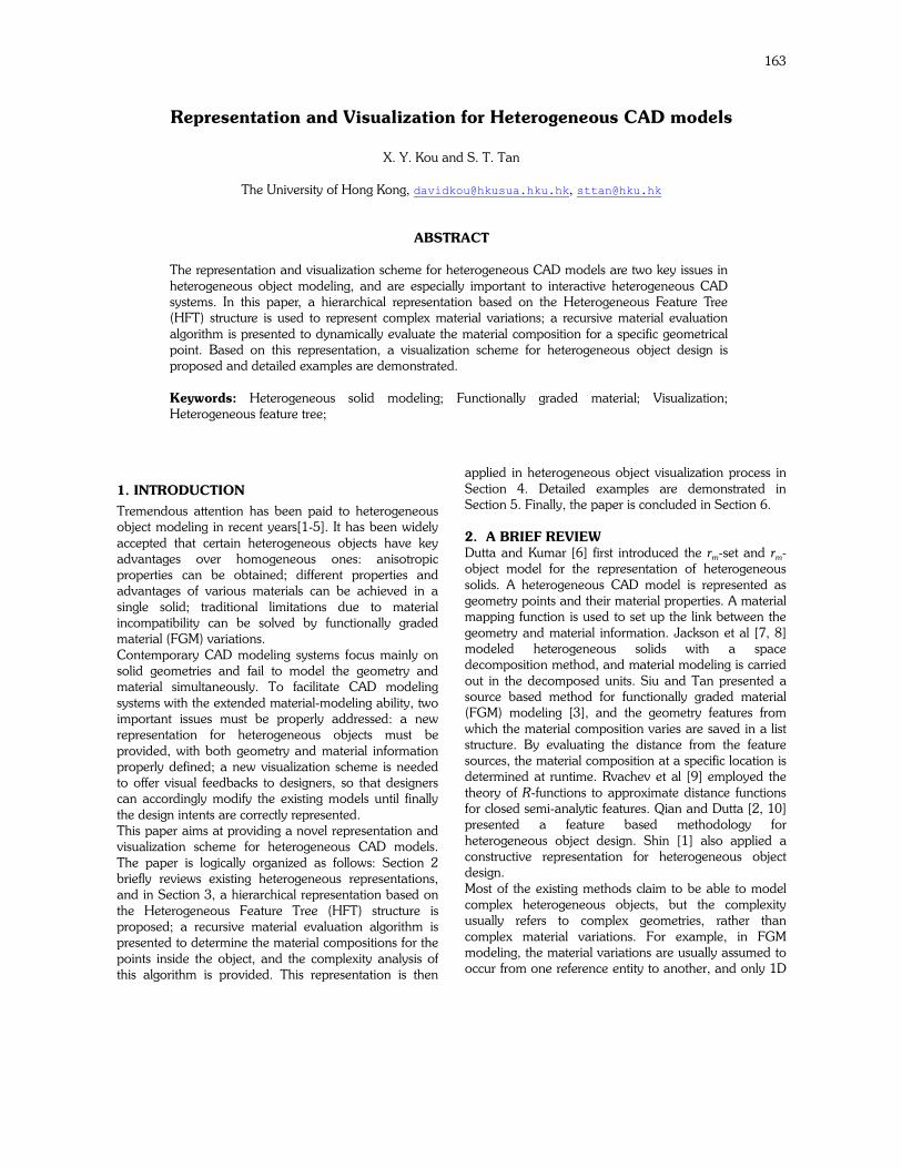
from the point under interrogation to the child features contributes to the material blending weights. Each HFT is composed of a collection of HFT nodes. Inside a typical HFT node, at least three parts of information are kept: the geometry pointer describing the feature’s geometry, a collection of pointers linking to its child feature nodes, and the weighting mode for material gradations. Key parameters in a typical HFT node and their descriptions are illustrated in Fig.1 and Tab.1.
Fig. 1. Key parameters in a HFT node.
Parameter Description
Geometry pointer
Points to either 1D, 2D or 3D geometries of a heterogeneous feature.
Child node i Points to the ith child feature node.
WEIGHT_MODE Controls how material blending weights for its child nodes are calculated, for example, constant weight or inverse-distance weight.
Tab. 1. Descriptions of key parameters in a HFT node.
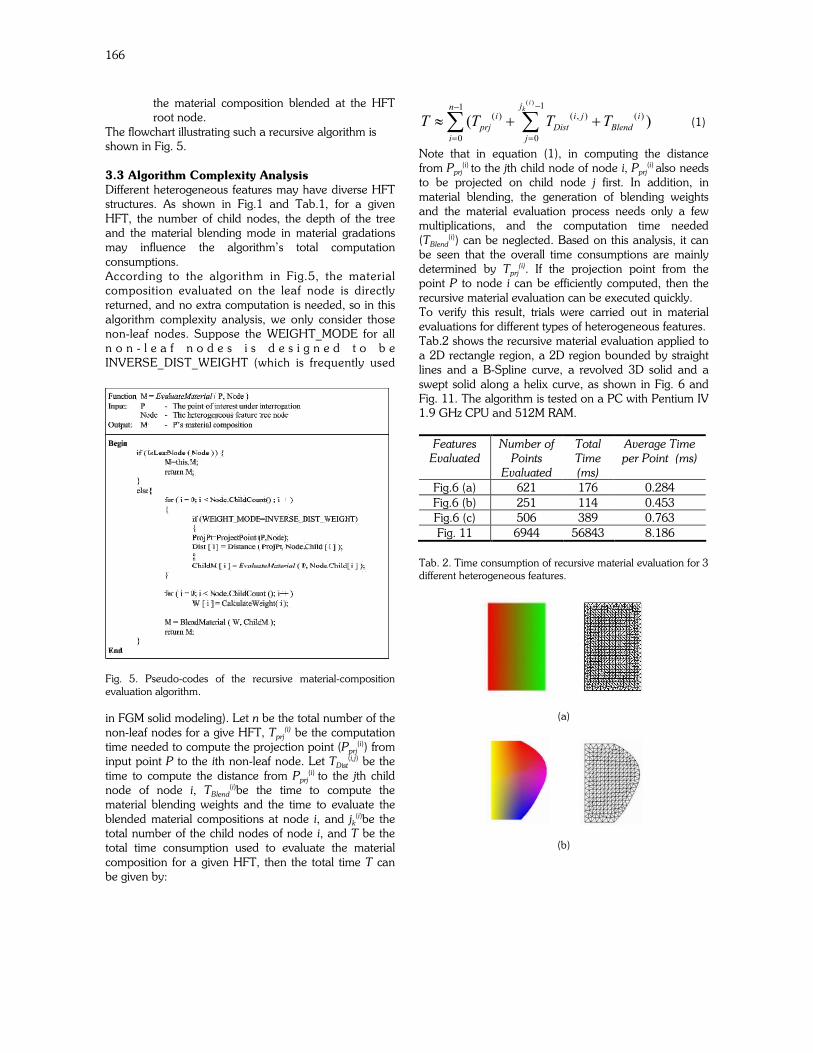
Based on the above definition for the heterogeneous feature tree structure, an example 3D heterogeneous extrusion solid in Fig.3 can be represented by a HFT structure shown in Fig.4. This extrusion solid is hierarchically constructed as follows:
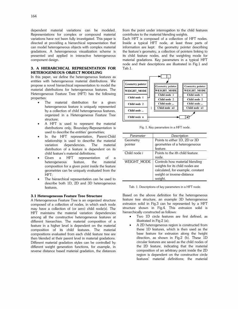
• Two 1D circle features are first defined, as illustrated in Fig.2 (a);
• A 2D heterogeneous region is constructed from these 1D features, which is then used as the base feature for extrusion along the height direction, as shown in Fig.2 (b). These 1D circular features are saved as the child nodes of the 2D feature, indicating that the material composition of an arbitrary point inside the 2D region is dependent on the constructive circle features’ material definitions; the material
165
blending weight is determined by the distance from the point to each constructive circle, and the parameter value of WEIGHT_MODE for this 2D region is assigned INVERSE_DIST_WEIGHT, indicating the inverse distance based weighting function is used in the material composition evaluation.
• Two 1D heterogeneous lines are defined as the heterogeneous extrusion vectors, which are introduced for the purpose of modeling material variations along the extrusion direction, as shown in Fig.2 (c). In this process, heterogeneous lines A and B are saved as the child nodes for the inner and outer circle features respectively, indicating that the circles’ material distributions are constrained by or dependent on these two heterogeneous lines and which in turn, will alter the material compositions of the extruded solid. Each heterogeneous extrusion line is also defined by its starting and ending points, and these points are homogeneous in material definitions.
(a) (b) (c)
Fig. 2. Construction of a 3D heterogeneous cylinder from 1D and 2D heterogeneous features.
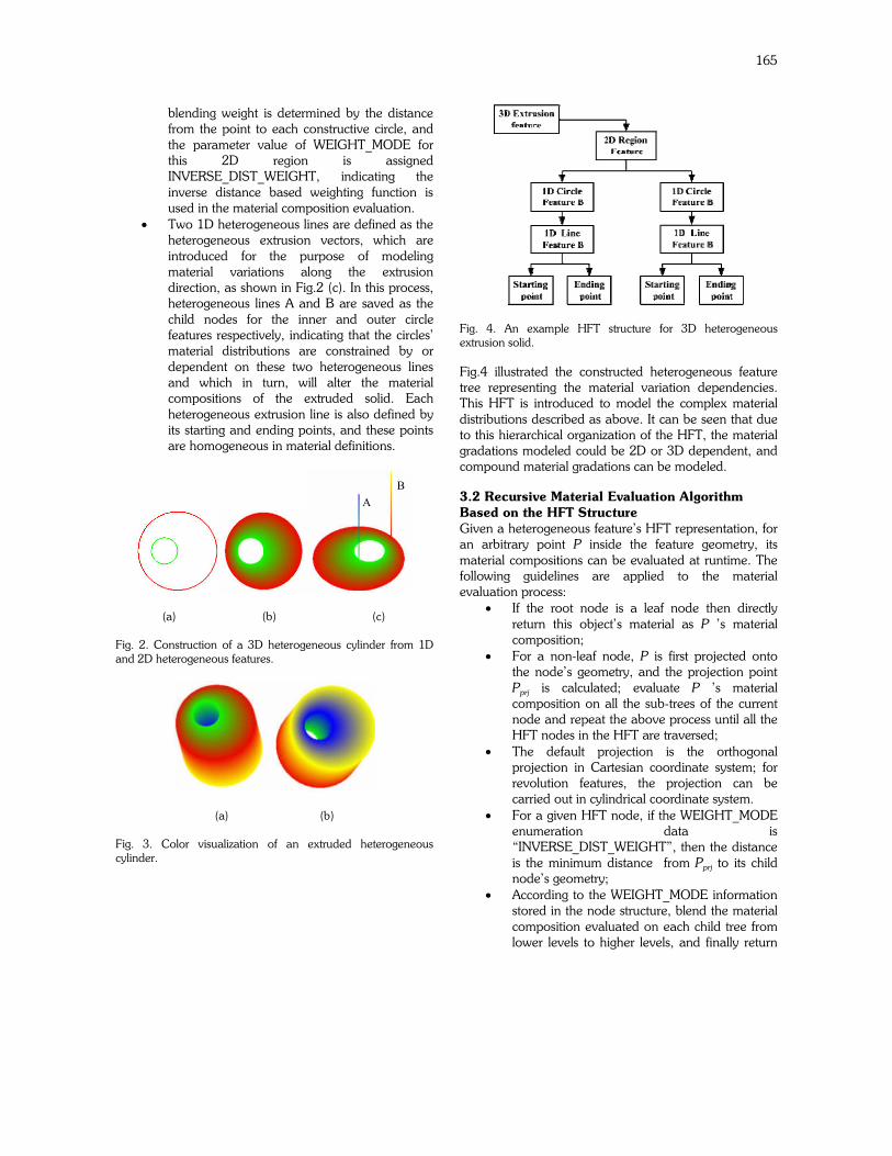
(a) (b)
Fig. 3. Color visualization of an extruded heterogeneous cylinder.
Fig. 4. An example HFT structure for 3D heterogeneous extrusion solid.
Fig.4 illustrated the constructed heterogeneous feature tree representing the material variation dependencies. This HFT is introduced to model the complex material distributions described as above. It can be seen that due to this hierarchical organization of the HFT, the material gradations modeled could be 2D or 3D dependent, and compound material gradations can be modeled.
3.2 Recursive Material Evaluation Algorithm
Based on the HFT Structure
Given a heterogeneous feature’s HFT representation, for an arbitrary point P inside the feature geometry, its material compositions can be evaluated at runtime. The following guidelines are applied to the material evaluation process:
• If the root node is a leaf node then directly return this object’s material as P ’s material composition;
• For a non-leaf node, P is first projected onto the node’s geometry, and the projection point Pprj is calculated; evaluate P ’s material composition on all the sub-trees of the current node and repeat the above process until all the HFT nodes in the HFT are traversed;
• The default projection is the orthogonal projection in Cartesian coordinate system; for revolution features, the projection can be carried out in cylindrical coordinate system.
• For a given HFT node, if the WEIGHT_MODE enumeration data is “INVERSE_DIST_WEIGHT”, then the distance is the minimum distance from Pprj to its child node’s geometry;
• According to the WEIGHT_MODE information stored in the node structure, blend the material composition evaluated on each child tree from lower levels to higher levels, and finally return
A
B
166
the material composition blended at the HFT root node.
The flowchart illustrating such a recursive algorithm is shown in Fig. 5. 3.3 Algorithm Complexity Analysis
Different heterogeneous features may have diverse HFT structures. As shown in Fig.1 and Tab.1, for a given HFT, the number of child nodes, the depth of the tree and the material blending mode in material gradations may influence the algorithm’s total computation consumptions. According to the algorithm in Fig.5, the material composition evaluated on the leaf node is directly returned, and no extra computation is needed, so in this algorithm complexity analysis, we only consider those non-leaf nodes. Suppose the WEIGHT_MODE for all n o n - l e a f n o d e s i s d e s i g n e d t o b e INVERSE_DIST_WEIGHT (which is frequently used
Fig. 5. Pseudo-codes of the recursive material-composition evaluation algorithm.
in FGM solid modeling). Let n be the total number of the non-leaf nodes for a give HFT, Tprj
(i) be the computation time needed to compute the projection point (Pprj
(i)) from input point P to the ith non-leaf node. Let TDist
(i,j) be the time to compute the distance from Pprj
(i) to the jth child node of node i, TBlend
(i)be the time to compute the material blending weights and the time to evaluate the blended material compositions at node i, and jk
(i)be the total number of the child nodes of node i, and T be the total time consumption used to evaluate the material composition for a given HFT, then the total time T can be given by:
( ) 11( ) ( , ) ( )
0 0
( )
ikjn
i i j i
prj Dist Blend
i j
T T T T−−
= =
≈ + +∑ ∑ (1)
Note that in equation (1), in computing the distance from Pprj
(i) to the jth child node of node i, Pprj(i) also needs
to be projected on child node j first. In addition, in material blending, the generation of blending weights and the material evaluation process needs only a few multiplications, and the computation time needed (TBlend
(i)) can be neglected. Based on this analysis, it can be seen that the overall time consumptions are mainly determined by Tprj
(i). If the projection point from the point P to node i can be efficiently computed, then the recursive material evaluation can be executed quickly. To verify this result, trials were carried out in material evaluations for different types of heterogeneous features. Tab.2 shows the recursive material evaluation applied to a 2D rectangle region, a 2D region bounded by straight lines and a B-Spline curve, a revolved 3D solid and a swept solid along a helix curve, as shown in Fig. 6 and Fig. 11. The algorithm is tested on a PC with Pentium IV 1.9 GHz CPU and 512M RAM.
Features
Evaluated
Number of
Points
Evaluated
Total
Time
(ms)
Average Time
per Point (ms)
Fig.6 (a) 621 176 0.284
Fig.6 (b) 251 114 0.453
Fig.6 (c) 506 389 0.763
Fig. 11 6944 56843 8.186
Tab. 2. Time consumption of recursive material evaluation for 3 different heterogeneous features.
(a)
(b)
167
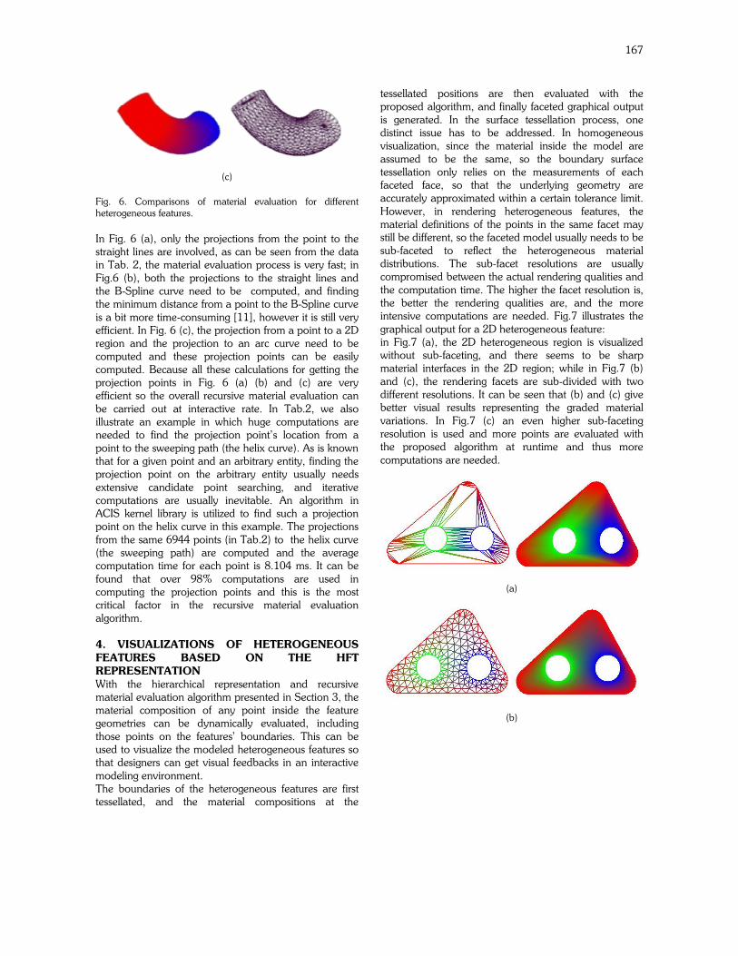
(c)
Fig. 6. Comparisons of material evaluation for different heterogeneous features.
In Fig. 6 (a), only the projections from the point to the straight lines are involved, as can be seen from the data in Tab. 2, the material evaluation process is very fast; in Fig.6 (b), both the projections to the straight lines and the B-Spline curve need to be computed, and finding the minimum distance from a point to the B-Spline curve is a bit more time-consuming [11], however it is still very efficient. In Fig. 6 (c), the projection from a point to a 2D region and the projection to an arc curve need to be computed and these projection points can be easily computed. Because all these calculations for getting the projection points in Fig. 6 (a) (b) and (c) are very efficient so the overall recursive material evaluation can be carried out at interactive rate. In Tab.2, we also illustrate an example in which huge computations are needed to find the projection point’s location from a point to the sweeping path (the helix curve). As is known that for a given point and an arbitrary entity, finding the projection point on the arbitrary entity usually needs extensive candidate point searching, and iterative computations are usually inevitable. An algorithm in ACIS kernel library is utilized to find such a projection point on the helix curve in this example. The projections from the same 6944 points (in Tab.2) to the helix curve (the sweeping path) are computed and the average computation time for each point is 8.104 ms. It can be found that over 98% computations are used in computing the projection points and this is the most critical factor in the recursive material evaluation algorithm. 4. VISUALIZATIONS OF HETEROGENEOUS
FEATURES BASED ON THE HFT
REPRESENTATION
With the hierarchical representation and recursive material evaluation algorithm presented in Section 3, the material composition of any point inside the feature geometries can be dynamically evaluated, including those points on the features’ boundaries. This can be used to visualize the modeled heterogeneous features so that designers can get visual feedbacks in an interactive modeling environment. The boundaries of the heterogeneous features are first tessellated, and the material compositions at the
tessellated positions are then evaluated with the proposed algorithm, and finally faceted graphical output is generated. In the surface tessellation process, one distinct issue has to be addressed. In homogeneous visualization, since the material inside the model are assumed to be the same, so the boundary surface tessellation only relies on the measurements of each faceted face, so that the underlying geometry are accurately approximated within a certain tolerance limit. However, in rendering heterogeneous features, the material definitions of the points in the same facet may still be different, so the faceted model usually needs to be sub-faceted to reflect the heterogeneous material distributions. The sub-facet resolutions are usually compromised between the actual rendering qualities and the computation time. The higher the facet resolution is, the better the rendering qualities are, and the more intensive computations are needed. Fig.7 illustrates the graphical output for a 2D heterogeneous feature: in Fig.7 (a), the 2D heterogeneous region is visualized without sub-faceting, and there seems to be sharp material interfaces in the 2D region; while in Fig.7 (b) and (c), the rendering facets are sub-divided with two different resolutions. It can be seen that (b) and (c) give better visual results representing the graded material variations. In Fig.7 (c) an even higher sub-faceting resolution is used and more points are evaluated with the proposed algorithm at runtime and thus more computations are needed.
(a)
(b)
168
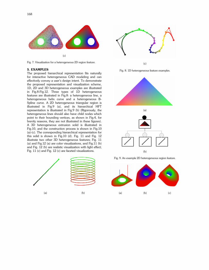
(c)
Fig. 7. Visualization for a heterogeneous 2D region feature.
5. EXAMPLES
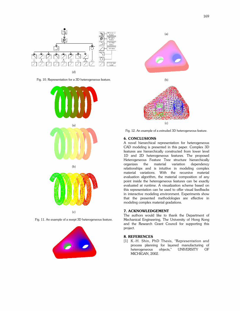
The proposed hierarchical representation fits naturally for interactive heterogeneous CAD modeling and can effectively convey a user’s design intent. To demonstrate the proposed representation and visualization scheme, 1D, 2D and 3D heterogeneous examples are illustrated in Fig.8-Fig.12. Three types of 1D heterogeneous features are illustrated in Fig.8: a heterogeneous line, a heterogeneous helix curve and a heterogeneous B-Spline curve. A 2D heterogeneous triangular region is illustrated in Fig.9 (a), and its hierarchical HFT representation is illustrated in Fig.9 (b) (Rigorously, the heterogeneous lines should also have child nodes which point to their bounding vertices, as shown in Fig.4, for brevity reasons, they are not illustrated in these figures). A 3D heterogeneous extrusion solid is illustrated in Fig.10, and the construction process is shown in Fig.10 (a)-(c). The corresponding hierarchical representation for this solid is shown in Fig.10 (d). Fig. 11 and Fig. 12 illustrate two other 3D heterogeneous features; Fig. 11 (a) and Fig.12 (a) are color visualizations, and Fig.11 (b) and Fig. 12 (b) are realistic visualization with light effect; Fig. 11 (c) and Fig. 12 (c) are faceted visualizations.
(a) (b)
(c)
Fig. 8. 1D heterogeneous feature examples.
(a)
(b)
Fig. 9. An example 2D heterogeneous region feature.
(a) (b) (c)
169
(d)
Fig. 10. Representation for a 3D heterogeneous feature.
(a)
(b)
(c)
Fig. 11. An example of a swept 3D heterogeneous feature.
(a)
(b)
(c)
Fig. 12. An example of a extruded 3D heterogeneous feature.
6. CONCLUSIONS
A novel hierarchical representation for heterogeneous CAD modeling is presented in this paper. Complex 3D features are hierarchically constructed from lower level 1D and 2D heterogeneous features. The proposed Heterogeneous Feature Tree structure hierarchically organizes the material variation dependency relationships and is intuitive in modeling complex material variations. With the recursive material evaluation algorithm, the material composition of any point inside the heterogeneous features can be exactly evaluated at runtime. A visualization scheme based on this representation can be used to offer visual feedbacks in interactive modeling environment. Experiments show that the presented methodologies are effective in modeling complex material gradations.
7. ACKNOWLEDGEMENT
The authors would like to thank the Department of Mechanical Engineering, The University of Hong Kong and the Research Grant Council for supporting this project.
8. REFERENCES
[1] K.-H. Shin, PhD Thesis, "Representation and process planning for layered manufacturing of heterogeneous objects," UNIVERSITY OF MICHIGAN, 2002.
170
[2] X. Qian and D. Dutta, "Design of heterogeneous turbine blade," Computer-Aided Design, vol. 35, pp. 319-329, 2003.
[3] Y. K. Siu and S. T. Tan, "'Source-based' heterogeneous solid modeling," Computer-Aided Design, vol. 34, pp. 41-55, 2002.
[4] E. Kartasheva, V. Adzhiev, A. Pasko, O. Fryazinov, and V. Gasilov, "Discretization of functionally based heterogeneous objects," ACM Symposium on Solid Modeling and Applications, Proceedings of the eighth ACM symposium on Solid modeling and applications, pp. 145 - 156, 2003.
[5] S.-M. Park, R. H. Crawford, and J. J. Beaman, "Volumetric multi-texturing for functionally gradient material representation," Proceedings of the sixth ACM symposium on Solid modeling and applications, 2001.
[6] V. Kumar and D. Dutta, "An Approach to Modeling Heterogeneous Objects," Proceedings of the Solid Freeform Fabrication Symposium, Austin, TX,, 1997.
[7] T. R. Jackson, N. M. Patrikalakis, E. M. Sachs, and M. J. Cima, "Modeling and Designing Components with Locally Controlled Composition," Solid Freeform Fabrication Proceedings,, pp. pp 259-266, 1998.
[8] T. R. Jackson and H. Liu, "Modeling and Designing Functionally Graded Material Components for Fabrication with Local Composition Control,," Materials and Design,, vol. Vol. 2 0, pp. pp.63-75, 1999.
[9] V. L. Rvachev, T. I. Sheiko, V. Shapiro, and I. Tsukanov, "Transfinite interpolation over implicitly defined sets," Computer Aided Geometric Design, vol. 18, pp. 195-220, 2001.
[10] X. Qian, PhD Thesis, "Feature methodologies for heterogeneous object realization," UNIVERSITY OF MICHIGAN, 2001.
[11] H. Wang, J. Kearney, and K. Atkinson, "Robust and Efficient Computation of the Closest Point on a Spline Curve," presented at Proceedings of the 5th International Conference on Curves and Surfaces, San Malo, France, 2002.