Embed Size (px)
Citation preview
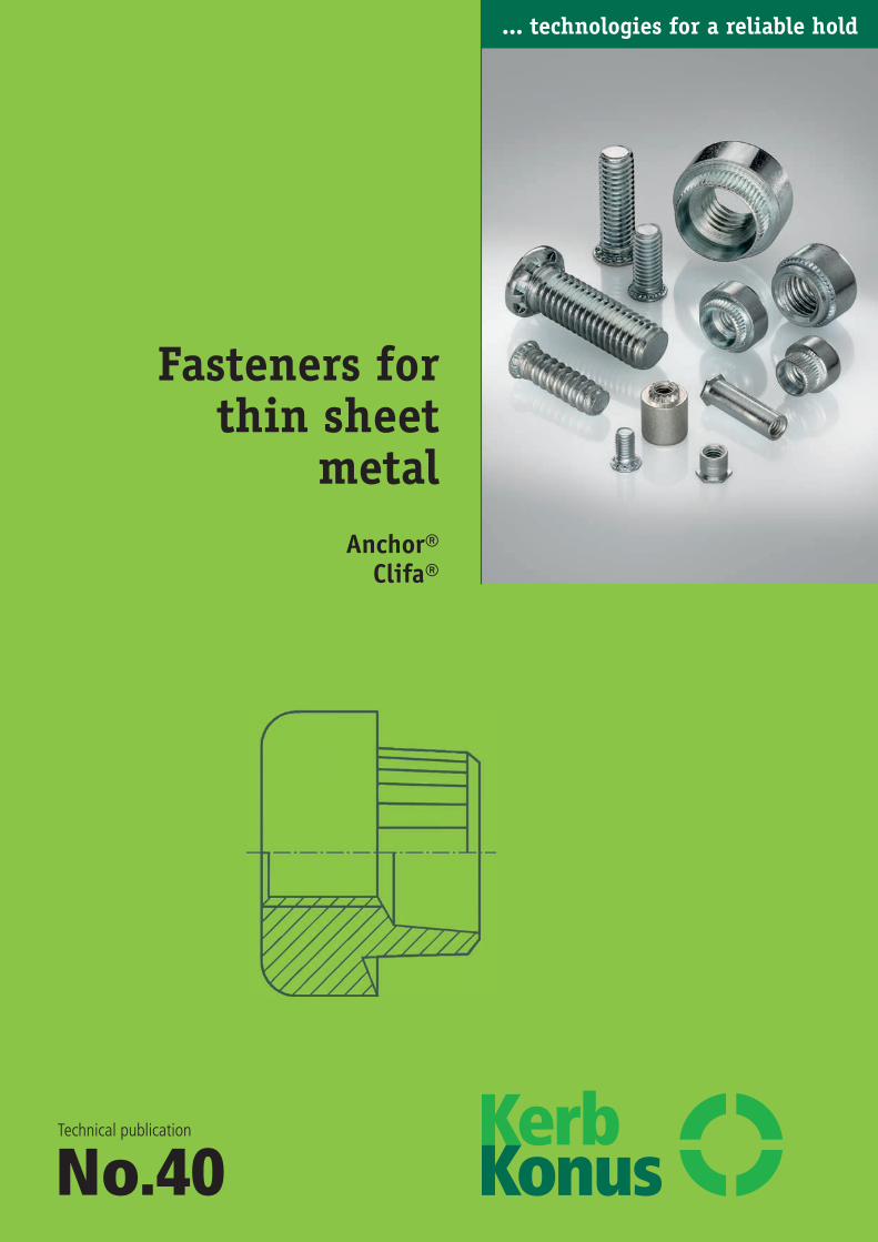
Fasteners forthin sheet
metalAnchor®
Clifa®
Technical publication
No.40
... technologies for a reliable hold
Kerb-Konus-Vertriebs-GmbHWernher-von-Braun-Straße 7 Gewerbegebiet Nord92224 Amberg
Phone +49 9621 679-0 Fax +49 9621 679444e-mail [email protected]
Internet www.kerbkonus.de
Fastening technology from KerbKonus are in successful appli-cations in a wide variety of different industrial sectors aroundthe world.
State-of-the-art production facilities provide our customers withthe assurance of quality and reliable delivery, and sophisticatedfastening solutions for every conceivable field of application areimplemented by our own Research and Development Depart-ment.
Close cooperation and exchange of experience and expertise onan international level ensure that our company stays at the cut-ting edge of technological development.
With independent branches and agencies operating in a numberof countries around the world we are a truly reliable partnerwhen it comes to secure fastening technology.
… our products and services
Depending on the required anchoring method in the material,KerbKonus offers a variety of threaded insert options:
• self-tapping threaded inserts for metal, wood and plastics,• Threaded inserts for cold embedding• Threaded inserts for hot or sound embedding• Threaded inserts for screwing into an internal thread• Threaded inserts for riveting
Alongside its long-standing, proven spectrum of threaded for awide variety of applications, KerbKonus also offers fasteningtechnology-related products and services:
• Punched rivet system for thin mouldings• Screw locking• Thread sealing systems• Insulating plastic coating
If you have a specific problem related to the field of fasteningtechnology – with its rich fund of expertise and comprehensive product range, KerbKonus has the solution for you.
Technical details on KerbKonus products are also provided onour homepage: www.kerbkonus.de
To access design data, go to the download portal of our website.Here, you will be able to download product data in any requiredformats or as CAD files.
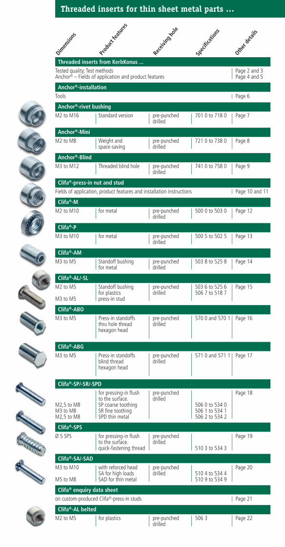
Threaded inserts for thin sheet metal parts …
Dimen
sions
Prod
uct f
eatu
res
Rece
iving
hole
Spec
ifica
tions
Other
det
ails
Threaded inserts from KerbKonus ...
Tested quality; Test methods Page 2 and 3 Anchor® – Fields of application and product features Page 4 and 5
Anchor®-installation
Tools Page 6
Anchor®-rivet bushing
M2 to M16 Standard version pre-punched 701 0 to 718 0 Page 7 drilled
Anchor®-Mini
M2 to M8 Weight and pre-punched 721 0 to 738 0 Page 8 space-saving drilled
Anchor®-Blind
M3 to M12 Threaded blind hole pre-punched 741 0 to 758 0 Page 9 drilled
Clifa®-press-in nut and stud
Fields of application, product features and installation instructions Page 10 and 11
Clifa®-M
M2 to M10 for metal pre-punched 500 0 to 503 0 Page 12 drilled
Clifa®-P
M3 to M10 for metal pre-punched 500 5 to 502 5 Page 13 drilled
Clifa®-AM
M3 to M5 Standoff bushing pre-punched 503 8 to 525 8 Page 14 for metal drilled
Clifa®-AL/-SL
M2 to M5 Standoff bushing pre-punched 503 6 to 525 6 Page 15 for plastics drilled 506 7 to 518 7
M3 to M5 press-in stud
Clifa®-ABO
M3 to M5 Press-in standoffs pre-punched 570 0 and 570 1 Page 16 thru hole thread drilled hexagon head
Clifa®-ABG
M3 to M5 Press-in standoffs pre-punched 571 0 and 571 1 Page 17 blind thread drilled hexagon head
Clifa®-SP/-SR/-SPD
for pressing-in flush pre-punched Page 18 to the surface. drilled
M2,5 to M8 SP coarse toothing 506 0 to 534 0M3 to M8 SR fine toothing 506 1 to 534 1M2,5 to M8 SPD thin metal 506 2 to 534 2
Clifa®-SPS
Ø 5 SPS for pressing-in flush pre-punched Page 19to the surface. drilledquick-fastening thread 510 3 to 534 3
Clifa®-SA/-SAD
M3 to M10 with reforced head pre-punched Page 20 SA for high loads drilled 510 4 to 534 4
M5 to M8 SAD for thin metal 510 9 to 534 9
Clifa® enquiry data sheet
on custom-produced Clifa®-press-in studs Page 21
Clifa®-AL belted
M2 to M5 for plastics pre-punched 506 3 Page 22 drilled
2
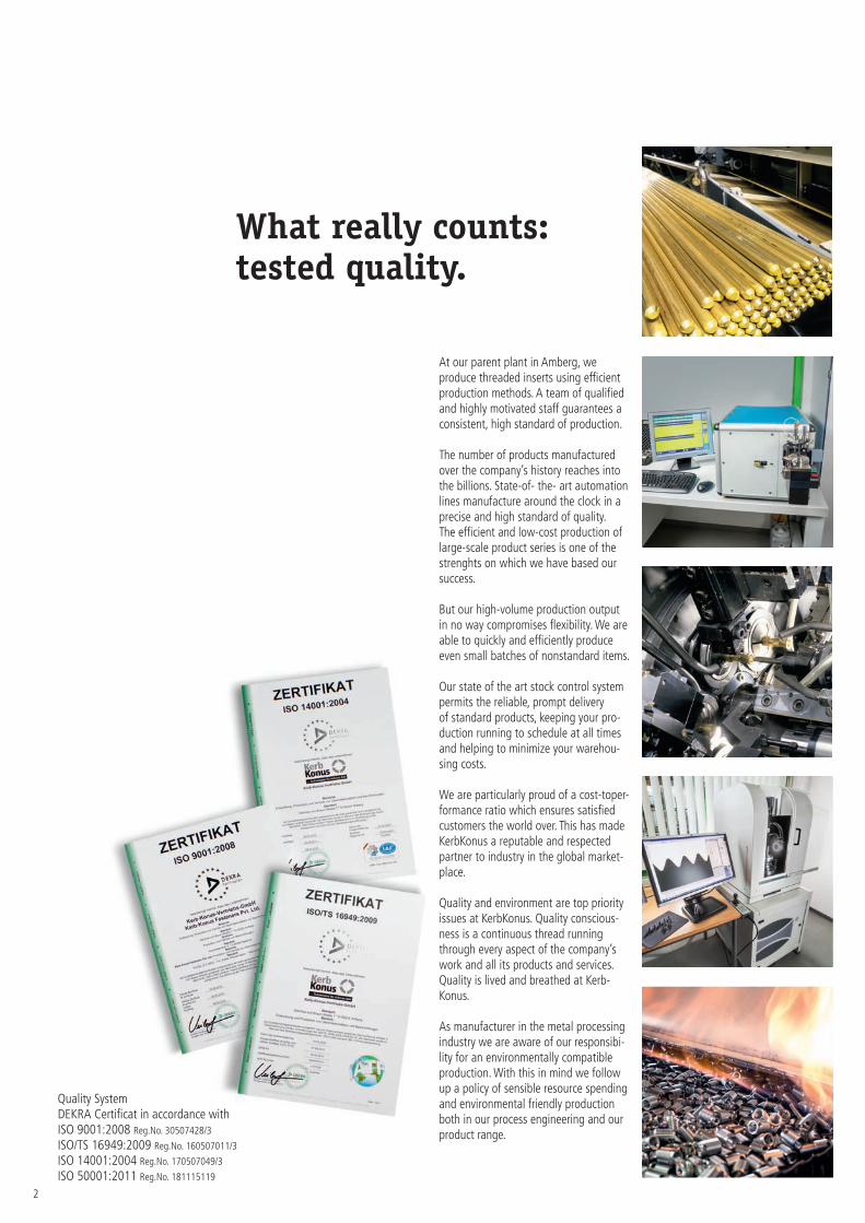
At our parent plant in Amberg, weproduce threaded inserts using efficientproduction methods. A team of qualifiedand highly motivated staff guarantees aconsistent, high standard of production.
The number of products manufacturedover the company’s history reaches intothe billions. State-of- the- art automationlines manufacture around the clock in aprecise and high standard of quality.The efficient and low-cost production oflarge-scale product series is one of thestrenghts on which we have based oursuccess.
But our high-volume production outputin no way compromises flexibility. We areable to quickly and efficiently produceeven small batches of nonstandard items.
Our state of the art stock control systempermits the reliable, prompt deliveryof standard products, keeping your pro-duction running to schedule at all timesand helping to minimize your warehou-sing costs.
We are particularly proud of a cost-toper-formance ratio which ensures satisfiedcustomers the world over. This has madeKerbKonus a reputable and respectedpartner to industry in the global market-place.
Quality and environment are top priorityissues at KerbKonus. Quality conscious-ness is a continuous thread runningthrough every aspect of the company’swork and all its products and services.Quality is lived and breathed at Kerb-Konus.
As manufacturer in the metal processingindustry we are aware of our responsibi-lity for an environmentally compatibleproduction. With this in mind we followup a policy of sensible resource spendingand environmental friendly productionboth in our process engineering and ourproduct range.
Quality SystemDEKRA Certificat in accordance withISO 9001:2008 Reg.No. 30507428/3
ISO/TS 16949:2009 Reg.No. 160507011/3
ISO 14001:2004 Reg.No. 170507049/3
ISO 50001:2011 Reg.No. 181115119
What really counts:tested quality.
3
... technologies for a reliable hold
Applications on thetest stand ...
Threaded inserts from KerbKonus aremanufactured in large piece numbers.Human lives and safety can oftendepend upon these tiny components,for instance in the case of airbagreceiving fasteners.
Because we bear this heavy responsibi-lity, our products are tested and moni-tored in line with the most stringentdirectives. In the case of particularlycritical applications, each and every partis exhaustively tested on state-of-the-art test equipment before it is delivered to you e.g. dimensional check,foreign particles. For Example:– dimensional check– foreign particles
Test methods
The loading capacity of a thread de-pends primarily on the surface shellof the component which is exposedto shearing stress.
By selecting just the right threadedinsert for each application, maximumreliability can be achieved.Using tried and tested, practically oriented test methods (see the tablebelow) set of reliable specifications toensure safe, reliable compliance withany application requirement, howeverunusual. In most cases, this can evenbe achieved using standard threadedinserts.
... technologies for a reliable hold
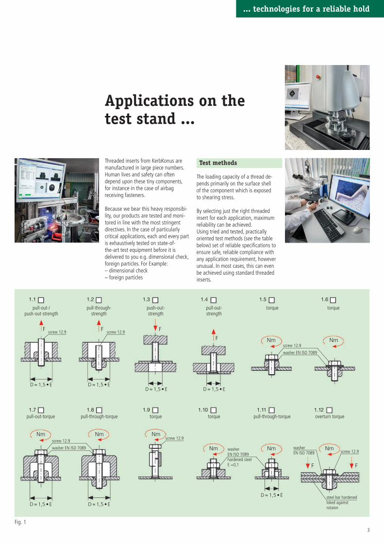
1.1 1.2 1.3 1.4 1.5 1.6
1.7 1.8 1.9 1.10 1.11 1.12
F F F
F Nm Nm
NmNmNm
NmNmNm
pull-out-/push-out-strength
pull-through-strength
push-out-strength
pull-out-strength
torque torque
D ≈ 1,5 • E D ≈ 1,5 • ED ≈ 1,5 • E D ≈ 1,5 • E
pull-out-torque pull-through-torque torque torque pull-through-torque overturn torque
D ≈ 1,5 • E D ≈ 1,5 • E
D ≈ 1,5 • E
F F
screw 12.9 screw 12.9
screw 12.9
washer EN ISO 7089
screw 12.9
washerEN ISO 7089hardened steelE +0,1
washerEN ISO 7089 screw 12.9
steel bar hardenedloked against rotaion
screw 12.9
washer EN ISO 7089
Fig. 1
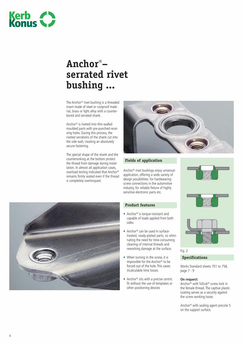
Fields of application
Anchor® rivet bushings enjoy universal-application, offering a wide variety ofdesign possibilities: for hardwearingscrew connections in the automotiveindustry, for reliable fixture of highlysensitive electronic parts etc.
Product features
• Anchor® is torque-resistant andcapable of loads applied from bothsides.
• Anchor® can be used in surface-treated, ready-plated parts, so elimi-nating the need for time-consumingcleaning of internal threads andreworking damage at the surface.
• When turning in the screw, it isimpossible for the Anchor® to beforced out of the hole. This savesincalculable time losses.
• Anchor® sits with a precise centric fit without the use of templates orother positioning devices
4
Anchor®–serrated rivetbushing ...The Anchor® rivet bushing is a threadedinsert made of steel or rustproof mate-rial, brass or light alloy with a counter-bored and serrated shank.
Anchor® is riveted into thin-walledmoulded parts with pre-punched recei-ving holes. During this process, theriveted serrations of the shank cut intothe side wall, creating an absolutely secure fastening.
The special shape of the shank and thecountersinking at the bottom protectthe thread from damage during instal-lation. In almost all application cases,overload testing indicated that Anchor®
remains firmly seated even if the threadis completely overtorqued.
Specifications
Works Standard sheets 701 to 758,page 7 - 9
On request:Anchor® with TufLok® screw lock in the female thread. The captive plasticcoating serves as a security against the screw working loose.
Anchor® with sealing agent precote 5on the support surface.
Fig. 2
5
... technologies for a reliable hold
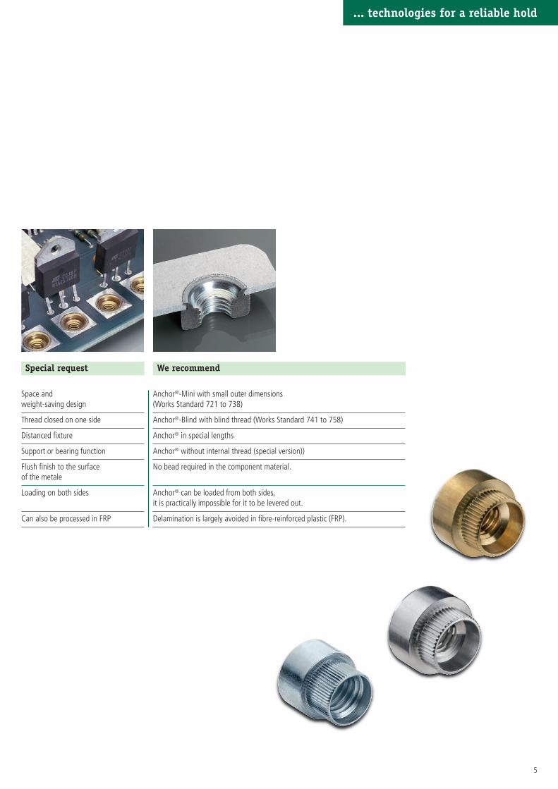
Special request
Space andweight-saving design
Thread closed on one side
Distanced fixture
Support or bearing function
Flush finish to the surfaceof the metale
Loading on both sides
Can also be processed in FRP
We recommend
Anchor®-Mini with small outer dimensions(Works Standard 721 to 738)
Anchor®-Blind with blind thread (Works Standard 741 to 758)
Anchor® in special lengths
Anchor® without internal thread (special version))
No bead required in the component material.
Anchor® can be loaded from both sides,it is practically impossible for it to be levered out.
Delamination is largely avoided in fibre-reinforced plastic (FRP).
... technologies for a reliable hold
6
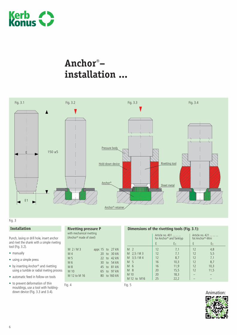
Anchor®–installation ...
Installation
Punch, lasing or drill hole, insert anchorand rivet the shank with a simple rivetingtool (Fig. 3.2).
• manually
• using a simple press
• by inserting Anchor® and rivettingusing a tumble or radial riveting process
• automatic feed in follow-on tools
• to prevent deformation of thin mouldings, use a tool with holding-down device (Fig. 3.3 and 3.4).
Fig. 3.1 Fig. 3.2 Fig. 3.3 Fig. 3.4
Rivetting pressure Pwith mechanical rivetting (Anchor® made of steel)
Dimensions of the rivetting tools (Fig. 3.1):
Article no. 401 ... ... ... Article no. 421 ... ... ...for Anchor® and Tanktyp fot Anchor®-Mini
M 2 / M 3 appr. 15 to 27 kNM 4 20 to 30 kNM 5 22 to 42 kNM 6 30 to 54 kNM 8 45 to 81 kNM 10 65 to 97 kNM 12 to M 16 80 to 160 kN
E E1 E E1
M 2 12 7,1 12 4,8 M 2,5 / M 3 12 7,1 12 5,5 M 3,5 / M 4 12 8,7 12 7,1 M 5 16 10,3 12 8,7 M 6 16 11,9 12 10,3 M 8 20 15,5 12 11,5 M 10 20 18,3 – –M 12 to M16 25 22,2 – –
Anchor®
Anchor®-retainer
Rivetting tool
Pressure body
Hold-down device
Sheet metal
Fig. 3
Fig. 4 Fig. 5
E 150 ±5
E1
Animation:
Article no. for sheet metalof the thickness
first groupof digits M
701 ... ... ... 0,5 to 0,6 1)702 ... ... ... 0,7 1)703 ... ... ... 0,8 1)704 ... ... ... 0,9 to 1,0 1)705 ... ... ... 1,1 to 1,3 1)706 ... ... ... 1,4 to 1,6 1)707 ... ... ... 1,7 to 1,9 2)708 ... ... ... 2,0 to 2,2 2)709 ... ... ... 2,3 to 2,5 2)710 ... ... ... 2,6 to 2,8 2)711 ... ... ... 2,9 to 3,1 2)712 ... ... ... 3,2 to 3,4 2)713 ... ... ... 3,5 to 3,7 2)714 ... ... ... 3,8 to 4,0 2)715 ... ... ... 4,1 to 4,3 2)716 ... ... ... 4,4 to 4,6 2)717 ... ... ... 4,7 to 4,9 2)718 . .. ... ... 5,0 2)
Exemple for finding Anchor® serrated rivet bushing with female thread M5; steel, galvanized,the article number blue passivated for sheet thickness 2 mm (sheet steel) Anchor® 708 000 050. 110 *)
Materials Steel, unrefined Article no. (fourth group of digits) … … … 100Steel, zinc plated, blue passivated Article no. (fourth group of digits) … … … 110Stahl, zinc-nickel plated, transparent passivated Article no. (fourth group of digits) … … … 143Stainless steel Article no. (fourth group of digits) … … … 500Light alloy Article no. (fourth group of digits) … … … 700Brass Article no. (fourth group of digits) … … … 800
Other materials and designs (e.g. nut height, shank lengths of deviating sheet metal thicknesses) on request.
Tolerances ISO 2768-m
Thread Internal thread A: as per ISO 6H
*) Remark For applications in high-strength steel sheet or stainless steel sheet, or when usingrivet bushings in stainless steel, for a flush riveting result, we recommendusing the rivet bushing with the next smallest shank length: 707 000 050. 110 (sheet thickness: 2 mm stainless steel of high-strength steel sheet).
Dimensions in mm
7
... technologies for a reliable hold
Kerb-Konus-Vertriebs-GmbH • P.O. Box 1663 • 92206 Amberg • Phone +49 9621 679-0 • Fax +49 9621 679444
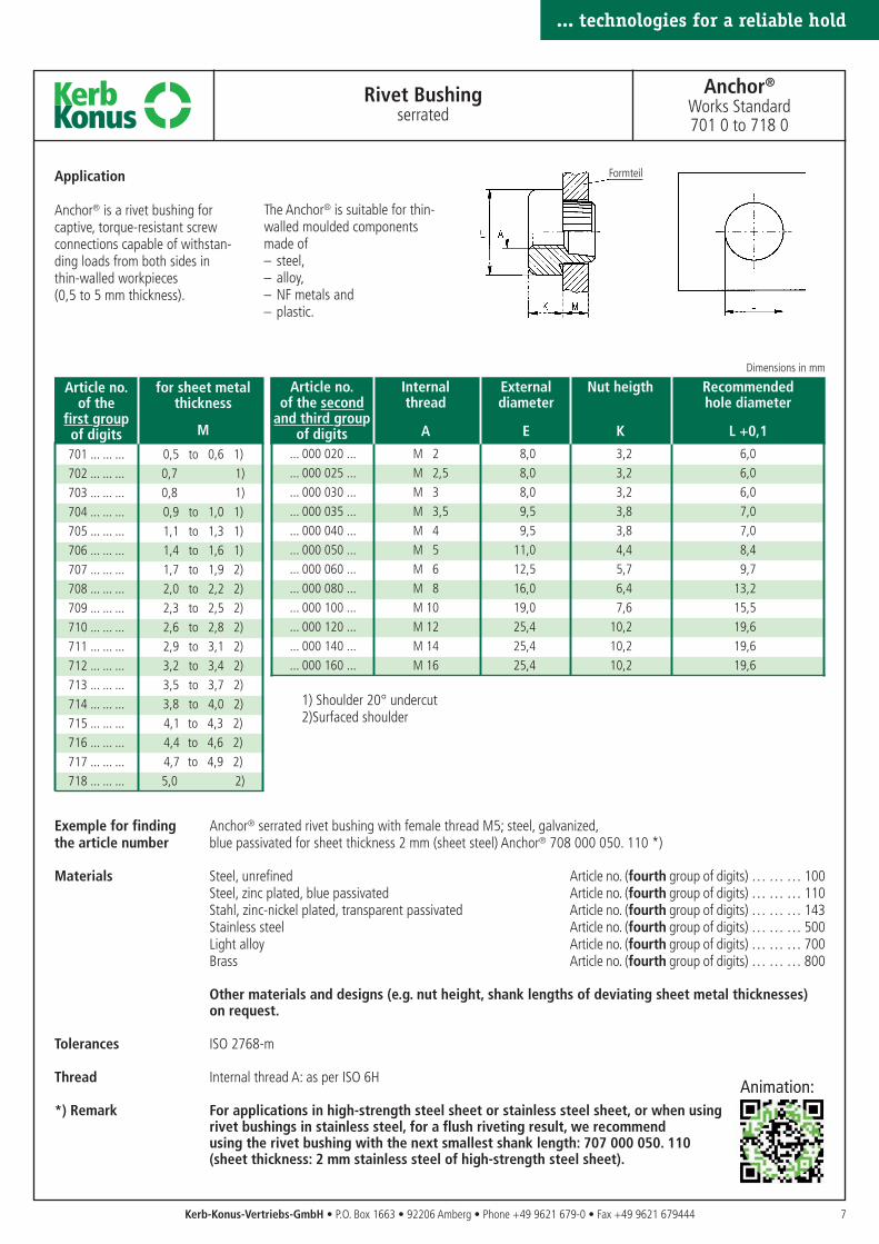
Rivet Bushingserrated
Anchor®
Works Standard701 0 to 718 0
Application
Anchor® is a rivet bushing for captive, torque-resistant screwconnections capable of withstan-ding loads from both sides in thin-walled workpieces(0,5 to 5 mm thickness).
The Anchor® is suitable for thin-walled moulded componentsmade of– steel,– alloy,– NF metals and– plastic.
Article no. Internal External Nut heigth Recommendedof the second thread diameter hole diameter
and third groupof digits A E K L +0,1
... 000 020 ... M 2 8,0 3,2 6,0
... 000 025 ... M 2,5 8,0 3,2 6,0
... 000 030 ... M 3 8,0 3,2 6,0
... 000 035 ... M 3,5 9,5 3,8 7,0
... 000 040 ... M 4 9,5 3,8 7,0
... 000 050 ... M 5 11,0 4,4 8,4
... 000 060 ... M 6 12,5 5,7 9,7
... 000 080 ... M 8 16,0 6,4 13,2
... 000 100 ... M 10 19,0 7,6 15,5
... 000 120 ... M 12 25,4 10,2 19,6
... 000 140 ... M 14 25,4 10,2 19,6
... 000 160 ... M 16 25,4 10,2 19,6
1) Shoulder 20° undercut2)Surfaced shoulder
... technologies for a reliable hold
Formteil
n: Animation:
Article no. Internal External Nut height Recommendedof the second thread diameter hole diameter
and third groupof digits A E K L +0,05
... 000 020 ... M 2 5,0 2,3 3,5
... 000 025 ... M 2,5 5,5 2,8 4,2
... 000 030 ... M 3 5,5 2,8 4,2
... 000 035 ... M 3,5 7,0 3,2 5,5
... 000 040 ... M 4 7,0 3,2 5,5
... 000 050 ... M 5 8,5 3,8 6,5
... 000 060 ... M 6 10,0 5,1 7,7
... 000 080 ... M 8 12,0 6,5 9,7
8 Kerb-Konus-Vertriebs-GmbH • P.O. Box 1663 • 92206 Amberg • Phone +49 9621 679-0 • Fax +49 9621 679444
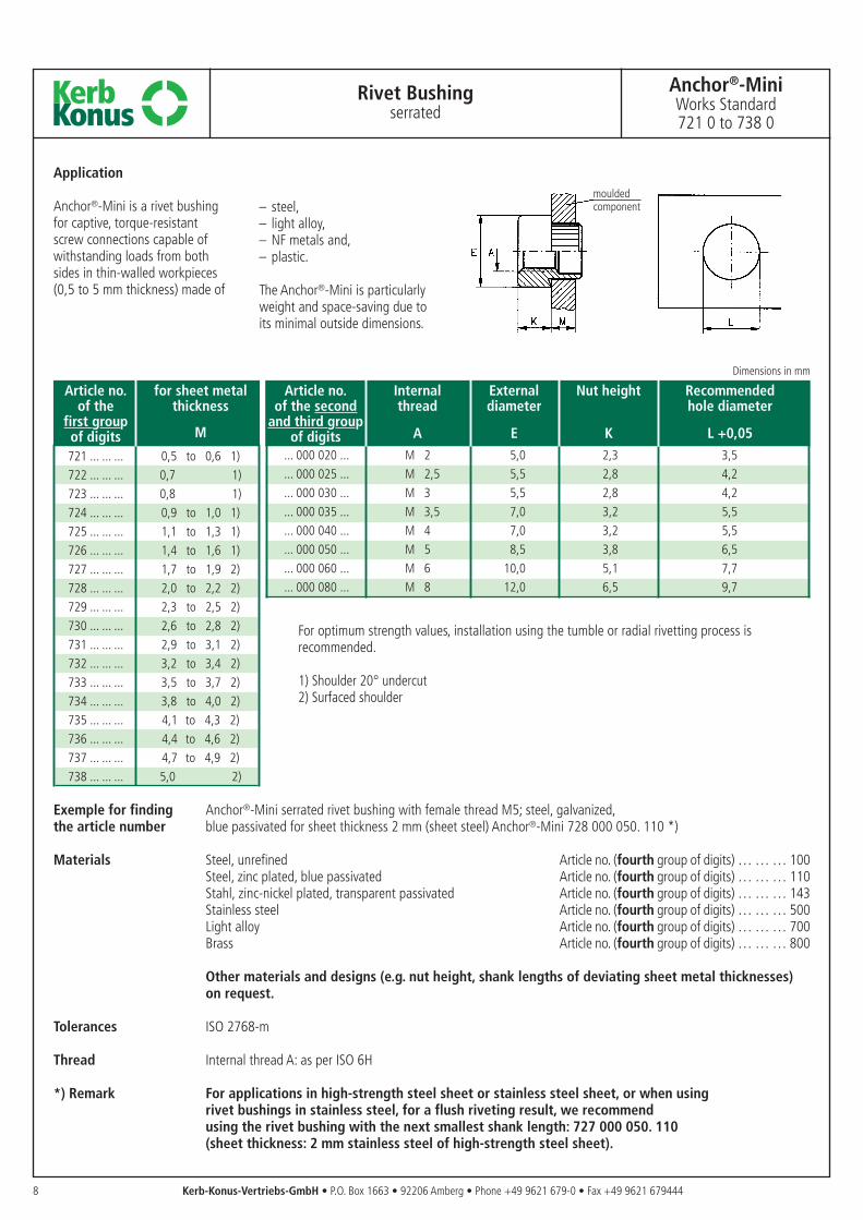
Rivet Bushingserrated
Anchor®-MiniWorks Standard721 0 to 738 0
Dimensions in mm
Application
Anchor®-Mini is a rivet bushingfor captive, torque-resistantscrew connections capable ofwithstanding loads from bothsides in thin-walled workpieces(0,5 to 5 mm thickness) made of
– steel,– light alloy,– NF metals and,– plastic.
The Anchor®-Mini is particularlyweight and space-saving due toits minimal outside dimensions.
For optimum strength values, installation using the tumble or radial rivetting process isrecommended.
1) Shoulder 20° undercut2) Surfaced shoulder
Exemple for finding Anchor®-Mini serrated rivet bushing with female thread M5; steel, galvanized,the article number blue passivated for sheet thickness 2 mm (sheet steel) Anchor®-Mini 728 000 050. 110 *)
Materials Steel, unrefined Article no. (fourth group of digits) … … … 100Steel, zinc plated, blue passivated Article no. (fourth group of digits) … … … 110Stahl, zinc-nickel plated, transparent passivated Article no. (fourth group of digits) … … … 143Stainless steel Article no. (fourth group of digits) … … … 500Light alloy Article no. (fourth group of digits) … … … 700Brass Article no. (fourth group of digits) … … … 800
Other materials and designs (e.g. nut height, shank lengths of deviating sheet metal thicknesses) on request.
Tolerances ISO 2768-m
Thread Internal thread A: as per ISO 6H
*) Remark For applications in high-strength steel sheet or stainless steel sheet, or when using rivet bushings in stainless steel, for a flush riveting result, we recommendusing the rivet bushing with the next smallest shank length: 727 000 050. 110 (sheet thickness: 2 mm stainless steel of high-strength steel sheet).
mouldedcomponent
Article no. for sheet metalof the thickness
first groupof digits M
721 ... ... ... 0,5 to 0,6 1)722 ... ... ... 0,7 1)723 ... ... ... 0,8 1)724 ... ... ... 0,9 to 1,0 1)725 ... ... ... 1,1 to 1,3 1)726 ... ... ... 1,4 to 1,6 1)727 ... ... ... 1,7 to 1,9 2)728 ... ... ... 2,0 to 2,2 2)729 ... ... ... 2,3 to 2,5 2)730 ... ... ... 2,6 to 2,8 2)731 ... ... ... 2,9 to 3,1 2)732 ... ... ... 3,2 to 3,4 2)733 ... ... ... 3,5 to 3,7 2)734 ... ... ... 3,8 to 4,0 2)735 ... ... ... 4,1 to 4,3 2)736 ... ... ... 4,4 to 4,6 2)737 ... ... ... 4,7 to 4,9 2)738 . .. ... ... 5,0 2)
Article no. Internal External Nut height Recommended Thread depthof the second thread diameter hole diameter min.
and third groupof digits A E K L +0,1 C
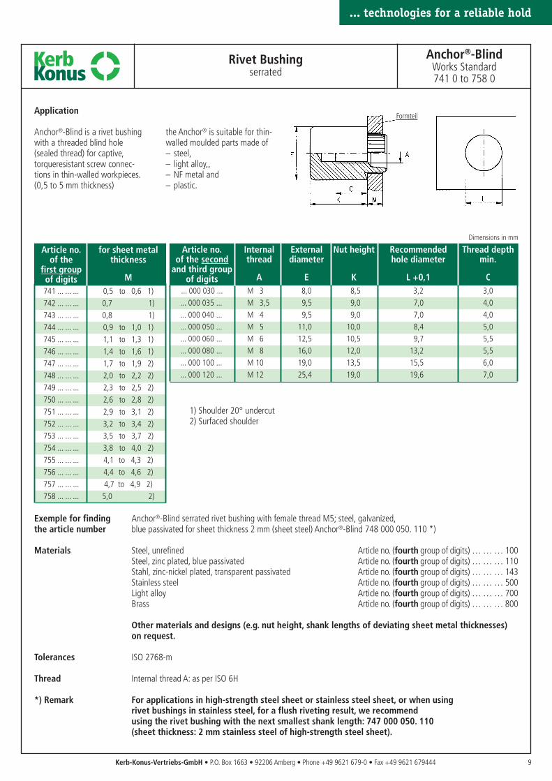
... 000 030 ... M 3 8,0 8,5 3,2 3,0... 000 035 ... M 3,5 9,5 9,0 7,0 4,0... 000 040 ... M 4 9,5 9,0 7,0 4,0... 000 050 ... M 5 11,0 10,0 8,4 5,0... 000 060 ... M 6 12,5 10,5 9,7 5,5... 000 080 ... M 8 16,0 12,0 13,2 5,5... 000 100 ... M 10 19,0 13,5 15,5 6,0... 000 120 ... M 12 25,4 19,0 19,6 7,0
Article no. for sheet metalof the thickness
first groupof digits M741 ... ... ... 0,5 to 0,6 1)742 ... ... ... 0,7 1)743 ... ... ... 0,8 1)744 ... ... ... 0,9 to 1,0 1)745 ... ... ... 1,1 to 1,3 1)746 ... ... ... 1,4 to 1,6 1)747 ... ... ... 1,7 to 1,9 2)748 ... ... ... 2,0 to 2,2 2)749 ... ... ... 2,3 to 2,5 2)750 ... ... ... 2,6 to 2,8 2)751 ... ... ... 2,9 to 3,1 2)752 ... ... ... 3,2 to 3,4 2)753 ... ... ... 3,5 to 3,7 2)754 ... ... ... 3,8 to 4,0 2)755 ... ... ... 4,1 to 4,3 2)756 ... ... ... 4,4 to 4,6 2)757 ... ... ... 4,7 to 4,9 2)758 ... ... ... 5,0 2)
9
... technologies for a reliable hold
Kerb-Konus-Vertriebs-GmbH • P.O. Box 1663 • 92206 Amberg • Phone +49 9621 679-0 • Fax +49 9621 679444
Rivet Bushingserrated
Anchor®-BlindWorks Standard741 0 to 758 0
Dimensions in mm
Application
Anchor®-Blind is a rivet bushingwith a threaded blind hole(sealed thread) for captive,torqueresistant screw connec-tions in thin-walled workpieces.(0,5 to 5 mm thickness)
the Anchor® is suitable for thin-walled moulded parts made of– steel,– light alloy,,– NF metal and– plastic.
Formteil
1) Shoulder 20° undercut2) Surfaced shoulder
Exemple for finding Anchor®-Blind serrated rivet bushing with female thread M5; steel, galvanized,the article number blue passivated for sheet thickness 2 mm (sheet steel) Anchor®-Blind 748 000 050. 110 *)
Materials Steel, unrefined Article no. (fourth group of digits) … … … 100Steel, zinc plated, blue passivated Article no. (fourth group of digits) … … … 110Stahl, zinc-nickel plated, transparent passivated Article no. (fourth group of digits) … … … 143Stainless steel Article no. (fourth group of digits) … … … 500Light alloy Article no. (fourth group of digits) … … … 700Brass Article no. (fourth group of digits) … … … 800
Other materials and designs (e.g. nut height, shank lengths of deviating sheet metal thicknesses) on request.
Tolerances ISO 2768-m
Thread Internal thread A: as per ISO 6H
*) Remark For applications in high-strength steel sheet or stainless steel sheet, or when using rivet bushings in stainless steel, for a flush riveting result, we recommendusing the rivet bushing with the next smallest shank length: 747 000 050. 110 (sheet thickness: 2 mm stainless steel of high-strength steel sheet).
... technologies for a reliable hold
10
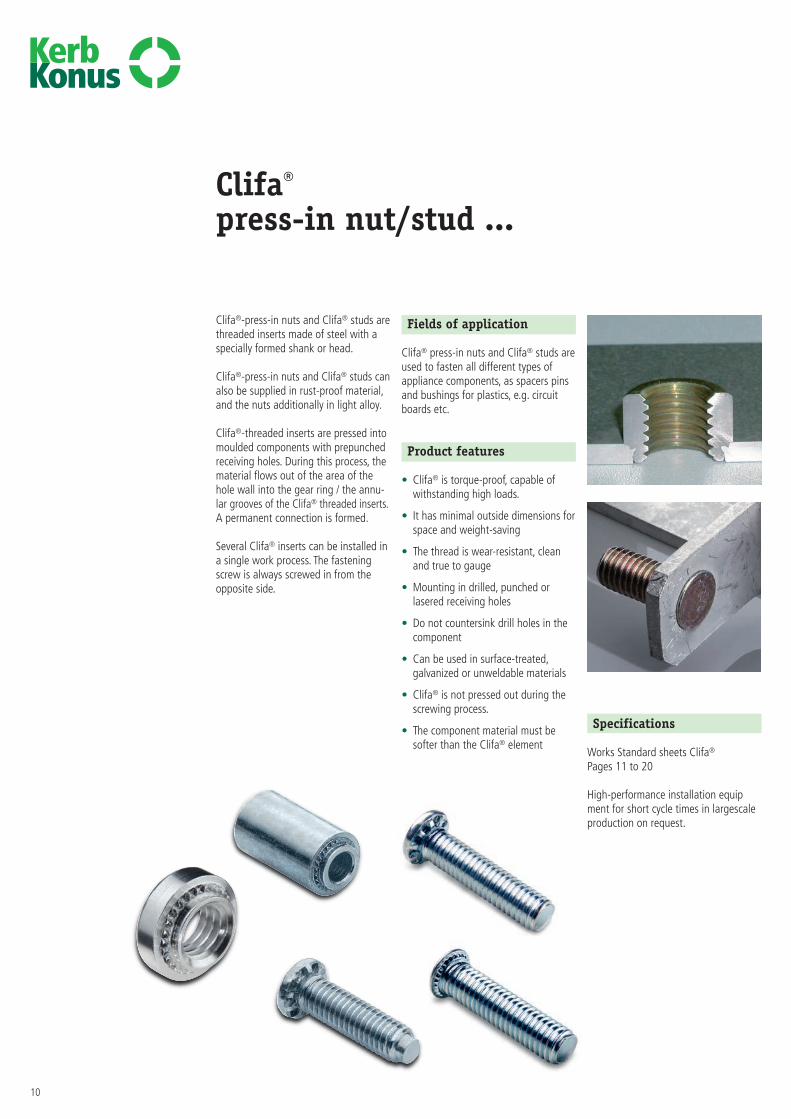
Clifa®
press-in nut/stud ...
Clifa®-press-in nuts and Clifa® studs arethreaded inserts made of steel with aspecially formed shank or head.
Clifa®-press-in nuts and Clifa® studs canalso be supplied in rust-proof material,and the nuts additionally in light alloy.
Clifa®-threaded inserts are pressed intomoulded components with prepunchedreceiving holes. During this process, thematerial flows out of the area of thehole wall into the gear ring / the annu-lar grooves of the Clifa® threaded inserts.A permanent connection is formed.
Several Clifa® inserts can be installed ina single work process. The fasteningscrew is always screwed in from theopposite side.
Fields of application
Clifa® press-in nuts and Clifa® studs areused to fasten all different types of appliance components, as spacers pinsand bushings for plastics, e.g. circuit boards etc.
Product features
• Clifa® is torque-proof, capable of withstanding high loads.
• It has minimal outside dimensions forspace and weight-saving
• The thread is wear-resistant, cleanand true to gauge
• Mounting in drilled, punched or lasered receiving holes
• Do not countersink drill holes in thecomponent
• Can be used in surface-treated, galvanized or unweldable materials
• Clifa® is not pressed out during thescrewing process.
• The component material must be softer than the Clifa® element
Specifications
Works Standard sheets Clifa®
Pages 11 to 20
High-performance installation equipment for short cycle times in largescaleproduction on request.
11
... technologies for a reliable hold
Clifa®
installation …
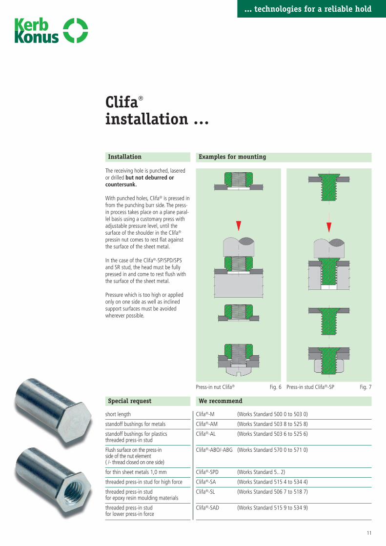
Installation
The receiving hole is punched, laseredor drilled but not deburred orcountersunk.
With punched holes, Clifa® is pressed infrom the punching burr side. The press-in process takes place on a plane paral-lel basis using a customary press withadjustable pressure level, until thesurface of the shoulder in the Clifa®
pressin nut comes to rest flat againstthe surface of the sheet metal.
In the case of the Clifa®-SP/SPD/SPSand SR stud, the head must be fullypressed in and come to rest flush withthe surface of the sheet metal.
Pressure which is too high or appliedonly on one side as well as inclinedsupport surfaces must be avoidedwherever possible.
Examples for mounting
Press-in nut Clifa® Press-in stud Clifa®-SP
Special request
short length
standoff bushings for metals
standoff bushings for plasticsthreaded press-in stud
Flush surface on the press-inside of the nut element( /- thread closed on one side)
for thin sheet metals 1,0 mm
threaded press-in stud for high force
threaded press-in stud for epoxy resin moulding materials
threaded press-in studfor lower press-in force
We recommend
Clifa®-M (Works Standard 500 0 to 503 0)
Clifa®-AM (Works Standard 503 8 to 525 8)
Clifa®-AL (Works Standard 503 6 to 525 6)
Clifa®-ABO/-ABG (Works Standard 570 0 to 571 0)
Clifa®-SPD (Works Standard 5.. 2)
Clifa®-SA (Works Standard 515 4 to 534 4)
Clifa®-SL (Works Standard 506 7 to 518 7)
Clifa®-SAD (Works Standard 515 9 to 534 9)
... technologies for a reliable hold
Fig. 6 Fig. 7
Clifa®-M, Clifa®-AM, Clifa®-P For shaped parts made of:
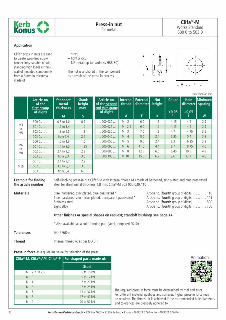
SteelM 2 / M 2,5 5 to 15 kNM 3 5 to 17 kNM 4 7 to 20 kNM 5 7 to 25 kNM 6 15 to 37 kNM 8 17 to 40 kNM 10 20 to 50 kN
Article no. Internal External Nut Collar Hole Minimumof the second thread diameter height diameter spacingand third group
of digits ±0,05 +0,05A E K E1 L W
… 000 020 ... M 2 6,0 1,6 4,15 4,2 2,9… 000 025 ... M 2,5 6,0 1,6 4,15 4,2 2,9… 000 030 ... M 3 7,0 1,6 4,7 4,75 3,6… 000 040 ... M 4 8,0 2,4 5,35 5,4 3,8… 000 050 ... M 5 9,0 2,4 6,3 6,35 3,8… 000 060 ... M 6 11,0 4,4 8,7 8,75 4,6… 000 080 ... M 8 12,5 6,0 10,45 10,5 4,8… 000 100 ... M 10 15,0 6,7 12,6 12,7 4,8
12 Kerb-Konus-Vertriebs-GmbH • P.O. Box 1663 • 92206 Amberg • Phone +49 9621 679-0 • Fax +49 9621 679444
Press-in nutfor metal
Clifa®-MWorks Standard500 0 to 503 0
Application
Clifa®-press-in nuts are used to create wear-free screw connections capable of with-standing high loads in thin-walled moulded componentsfrom 0,8 mm in thickness made of
– steel,– light alloy,,– NF metal (up to hardness HRB 80).
The nut is anchored in the componentas a result of the press-in process.
The required press-in force must be determined by trial and error. For different material qualities and surfaces, higher press-in force may be required. The firmest fit is achieved if the recommended hole diametersand tolerances are precisely adhered to.
Dimensions in mm
Article no. for sheet Shank of the metal height
first group thickness max.of digits
M S500 0.. ... ... 0,8 to 1,0 0,7501 0.. ... ... 1,1 to 1,4 1,0502 0.. ... ... 1,5 to 2,3 1,3503 0.. ... ... from 2,4 2,2500 0.. ... ... 1,0 to 1,3 1,0501 0.. ... ... 1,4 to 2,3 1,35502 0.. ... ... 2,4 to 3,2 2,2503 0.. ... ... from 3,3 3,0501 0.. ... ... 2,4 to 3,2 2,2502 0.. ... ... 3,3 to 6,3 3,0503 0.. ... ... from 6,4 6,0
M3toM5
M6toM8
M10
Example for finding Self-clinching press-in nut Clifa®-M with internal thread M3 made of hardened, zinc plated and blue passivatedthe article number steel for sheet metal thickness 1,8 mm: Clifa®-M 502 000 030.110
Materials Steel hardened, zinc plated, blue passivated * Article no. (fourth group of digits) … … … 110Steel hardened, zinc-nickel plated, transparent passivated * Article no. (fourth group of digits) … … … 143Stainless steel Article no. (fourth group of digits) … … … 500Light alloy Article no. (fourth group of digits) … … … 700
Other finishes or special shapes on request; standoff bushings see page 14.
* Also available as a cold-forming part (steel, tempered FK10).
Tolerances ISO 2768-m
Thread Internal thread A: as per ISO 6H
Press-in force as a guideline value for selection of the press.
Animation:
M4toM5
M6
M8
M10
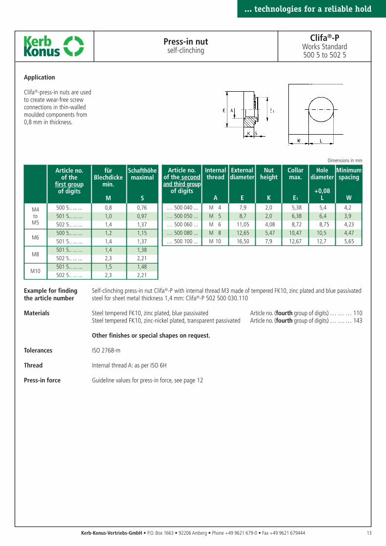
Example for finding Self-clinching press-in nut Clifa®-P with internal thread M3 made of tempered FK10, zinc plated and blue passivatedthe article number steel for sheet metal thickness 1,4 mm: Clifa®-P 502 500 030.110
Materials Steel tempered FK10, zinc plated, blue passivated Article no. (fourth group of digits) … … … 110Steel tempered FK10, zinc-nickel plated, transparent passivated Article no. (fourth group of digits) … … … 143
Other finishes or special shapes on request.
Tolerances ISO 2768-m
Thread Internal thread A: as per ISO 6H
Press-in force Guideline values for press-in force, see page 12
13
... technologies for a reliable hold
Kerb-Konus-Vertriebs-GmbH • P.O. Box 1663 • 92206 Amberg • Phone +49 9621 679-0 • Fax +49 9621 679444
Press-in nutself-clinching
Clifa®-PWorks Standard500 5 to 502 5
Application
Clifa®-press-in nuts are usedto create wear-free screwconnections in thin-walledmoulded components from0,8 mm in thickness.
Article no. Internal External Nut Collar Hole Minimumof the second thread diameter height max. diameter spacingand third group
of digits +0,08A E K E1 L W
… 500 040 ... M 4 7,9 2,0 5,38 5,4 4,2… 500 050 ... M 5 8,7 2,0 6,38 6,4 3,9… 500 060 ... M 6 11,05 4,08 8,72 8,75 4,23… 500 080 ... M 8 12,65 5,47 10,47 10,5 4,47… 500 100 ... M 10 16,50 7,9 12,67 12,7 5,65
Dimensions in mm
Article no. für Schafthöheof the Blechdicke maximal
first group min.of digits
M S500 5.. ... ... 0,8 0,76501 5.. ... ... 1,0 0,97502 5.. ... ... 1,4 1,37500 5.. ... ... 1,2 1,15501 5.. ... ... 1,4 1,37501 5.. ... ... 1,4 1,38502 5.. ... ... 2,3 2,21501 5.. ... ... 1,5 1,48502 5.. ... ... 2,3 2,21
... technologies for a reliable hold
14 Kerb-Konus-Vertriebs-GmbH • P.O. Box 1663 • 92206 Amberg • Phone +49 9621 679-0 • Fax +49 9621 679444
Press-in nut / standoff bushingsfor metal
Clifa®-AMWorks Standard503 8 to 525 8
Formteil Formteil
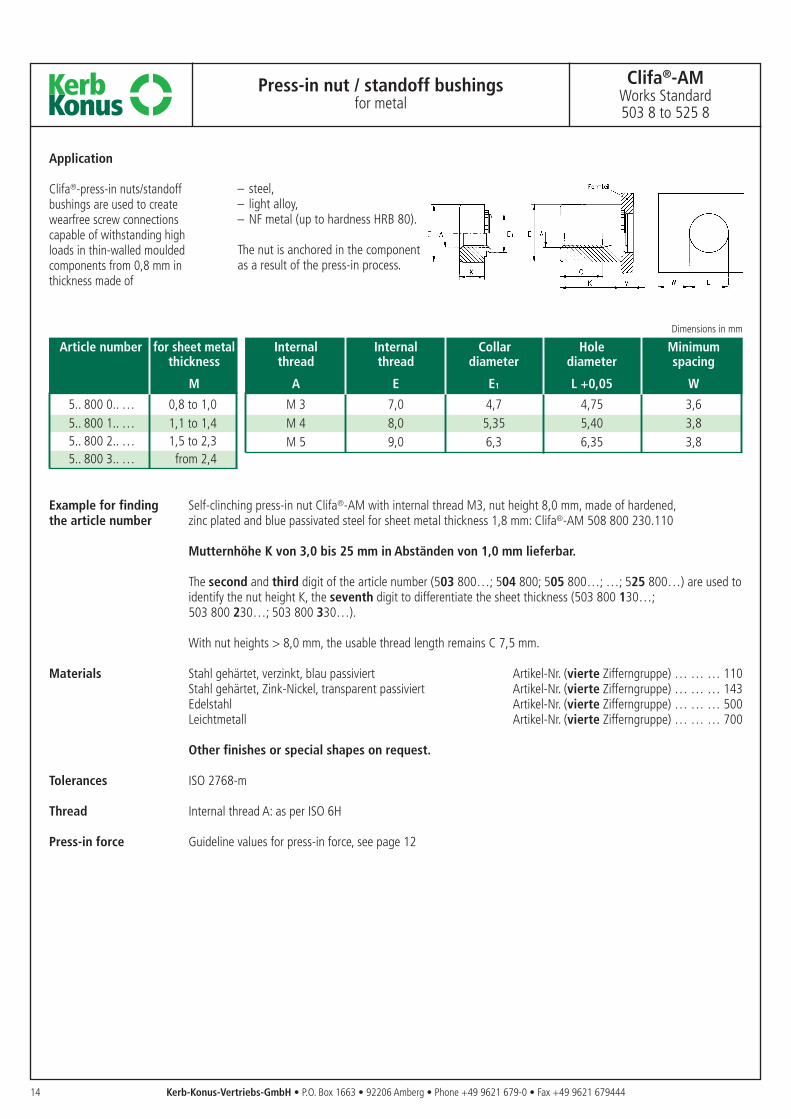
Application
Clifa®-press-in nuts/standoffbushings are used to createwearfree screw connectionscapable of withstanding highloads in thin-walled mouldedcomponents from 0,8 mm inthickness made of
Example for finding Self-clinching press-in nut Clifa®-AM with internal thread M3, nut height 8,0 mm, made of hardened, the article number zinc plated and blue passivated steel for sheet metal thickness 1,8 mm: Clifa®-AM 508 800 230.110
Mutternhöhe K von 3,0 bis 25 mm in Abständen von 1,0 mm lieferbar.
The second and third digit of the article number (503 800…; 504 800; 505 800…; …; 525 800…) are used toidentify the nut height K, the seventh digit to differentiate the sheet thickness (503 800 130…; 503 800 230…; 503 800 330…).
With nut heights > 8,0 mm, the usable thread length remains C 7,5 mm.
Materials Stahl gehärtet, verzinkt, blau passiviert Artikel-Nr. (vierte Zifferngruppe) … … … 110Stahl gehärtet, Zink-Nickel, transparent passiviert Artikel-Nr. (vierte Zifferngruppe) … … … 143Edelstahl Artikel-Nr. (vierte Zifferngruppe) … … … 500Leichtmetall Artikel-Nr. (vierte Zifferngruppe) … … … 700
Other finishes or special shapes on request.
Tolerances ISO 2768-m
Thread Internal thread A: as per ISO 6H
Press-in force Guideline values for press-in force, see page 12
Article number for sheet metalthickness
M
5.. 800 0.. … 0,8 to 1,05.. 800 1.. … 1,1 to 1,45.. 800 2.. … 1,5 to 2,35.. 800 3.. … from 2,4
Internal Internal Collar Hole Minimumthread thread diameter diameter spacing
A E E1 L +0,05 W
M 3 7,0 4,7 4,75 3,6M 4 8,0 5,35 5,40 3,8M 5 9,0 6,3 6,35 3,8
Dimensions in mm
– steel,– light alloy,– NF metal (up to hardness HRB 80).
The nut is anchored in the componentas a result of the press-in process.
2P Steel hardened3P Stainless steel
15
... technologies for a reliable hold
Kerb-Konus-Vertriebs-GmbH • P.O. Box 1663 • 92206 Amberg • Phone +49 9621 679-0 • Fax +49 9621 679444
... technologies for a reliable hold
Press-in nut / standoff bushingsfor plastics
Clifa®-ALWorks Standard503 6 to 525 6
Press-in studfor plastics
Clifa®-SLWorks Standard506 7 to 518 7
mouldedcomponent
mouldedcomponent
Application
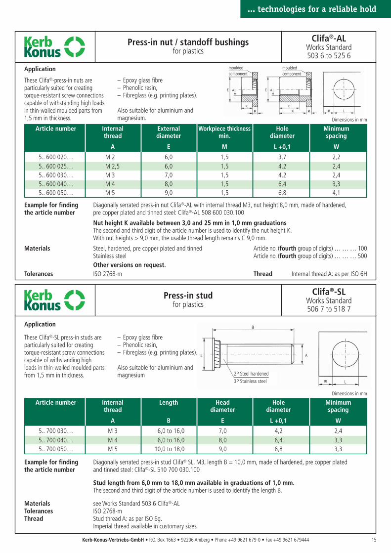
These Clifa®-press-in nuts are particularly suited for creating torque-resistant screw connectionscapable of withstanding high loadsin thin-walled moulded parts from1,5 mm in thickness.
– Epoxy glass fibre– Phenolic resin,– Fibreglass (e.g. printing plates).
Also suitable for aluminium andmagnesium.
Application
These Clifa®-SL press-in studs areparticularly suited for creatingtorque-resistant screw connectionscapable of withstanding highloads in thin-walled moulded partsfrom 1,5 mm in thickness.
– Epoxy glass fibre– Phenolic resin,– Fibreglass (e.g. printing plates).
Also suitable for aluminium andmagnesium
Example for finding Diagonally serrated press-in nut Clifa®-AL with internal thread M3, nut height 8,0 mm, made of hardened,the article number pre copper plated and tinned steel: Clifa®-AL 508 600 030.100
Nut height K available between 3,0 and 25 mm in 1,0 mm graduationsThe second and third digit of the article number is used to identify the nut height K.With nut heights > 9,0 mm, the usable thread length remains C 9,0 mm.
Materials Steel, hardened, pre copper plated and tinned Article no. (fourth group of digits) … … … 100Stainless steel Article no. (fourth group of digits) … … … 500Other versions on request.
Tolerances ISO 2768-m Thread Internal thread A: as per ISO 6H
Example for finding Diagonally serrated press-in stud Clifa® SL, M3, length B = 10,0 mm, made of hardened, pre copper platedthe article number and tinned steel: Clifa®-SL 510 700 030.100
Stud length from 6,0 mm to 18,0 mm available in graduations of 1,0 mm.The second and third digit of the article number is used to identify the length B.
Materials see Works Standard 503 6 Clifa®-ALTolerances ISO 2768-mThread Stud thread A: as per ISO 6g.
Imperial thread available in customary sizes
Article number Internal Length Head Hole Minimumthread diameter diameter spacing
A B E L +0,1 W
5.. 700 030… M 3 6,0 to 16,0 7,0 4,2 2,45.. 700 040… M 4 6,0 to 16,0 8,0 6,4 3,35.. 700 050… M 5 10,0 to 18,0 9,0 6,8 3,3
Dimensions in mm
Article number Internal External Workpiece thickness Hole Minimumthread diameter min. diameter spacing
A E M L +0,1 W
5.. 600 020… M 2 6,0 1,5 3,7 2,25.. 600 025… M 2,5 6,0 1,5 4,2 2,45.. 600 030… M 3 7,0 1,5 4,2 2,45.. 600 040… M 4 8,0 1,5 6,4 3,35.. 600 050… M 5 9,0 1,5 6,8 4,1
Dimensions in mm
Clifa® ABO Press-in forceM 3 20 to 25 kNM 4 30 to 40 kNM 5 40 to 50 kN
16 Kerb-Konus-Vertriebs-GmbH • P.O. Box 1663 • 92206 Amberg • Phone +49 9621 679-0 • Fax +49 9621 679444
Press-fit threaded standoff bushings– thru-hole-thread –
for metal
Clifa®-ABOWorks Standard570 0 to 570 1
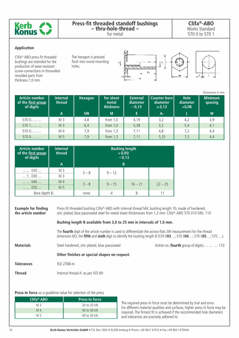
Application
Clifa®-ABO press-fit threadedbushings are intended for theproduction of wear-resistantscrew-connections in thinwalledmoulded parts from thickness 1,0 mm.
The hexagon is pressed flush into round mountingholes.
The required press-in force must be determined by trial and error. For different material qualities and surfaces, higher press-in force may berequired. The firmest fit is achieved if the recommended hole diametersand tolerances are precisely adhered to.
Example for finding Press-fit threaded bushing Clifa®-ABO with internal thread M4, bushing length 10, made of hardened,the article number zinc plated, blue passivated steel for metal sheet thicknesses from 1,3 mm: Clifa®-ABO 570 010 040. 110
Bushing length B available from 3,0 to 25 mm in intervals of 1,0 mm.
The fourth digit of the article number is used to differentiate the across-flats SW measurement for the thread dimension M3, the fifth and sixth digit to identify the bushing length B (570 003…; 570 004…; 570 005…; 570 …).
Materials Steel hardened, zinc plated, blue passivated Article no. (fourth group of digits) … … … 110
Other finishes or special shapes on request.
Tolerances ISO 2768-m
Thread Internal thread A: as per ISO 6H
Press-in force as a guideline value for selection of the press
Article number Internal Hexagon for sheet External Counter bore Hole Minimumof the first group thread metal diameter diameter diameter spacing
of digits thickness – 0,13 ± 0,13 +0,08
A SW M E A1 L W
570 0.. ... … M 3 4,8 from 1,0 4,19 3,2 4,2 3,9570 1.. ... … M 3 6,4 from 1,0 5,38 3,2 5,4 4,1570 0.. ... … M 4 7,9 from 1,3 7,11 4,8 7,2 4,4570 0.. ... … M 5 7,9 from 1,3 7,11 5,35 7,2 4,4
Article number Internal Bushing lengthof the first group thread + 0,05/
of digits – 0,13
A B
... ... 030 ... M 33 – 8 9 – 12
... 1.. 030 ... M 3
... ... 040 ... M 43 – 8 9 – 15 16 – 21 22 – 25
... ... 050 ... M 5Bore depth B1 none 4 8 11
Dimensions in mm
Clifa® ABG Press-in forceM 3 20 to 25 kNM 4 30 to 40 kNM 5 40 to 50 kN
17
... technologies for a reliable hold
Kerb-Konus-Vertriebs-GmbH • P.O. Box 1663 • 92206 Amberg • Phone +49 9621 679-0 • Fax +49 9621 679444
... technologies for a reliable hold
Press-fit threaded standoff bushings– blind thread –
for metal
Clifa®-ABGWorks Standard571 0 to 571 1
Application
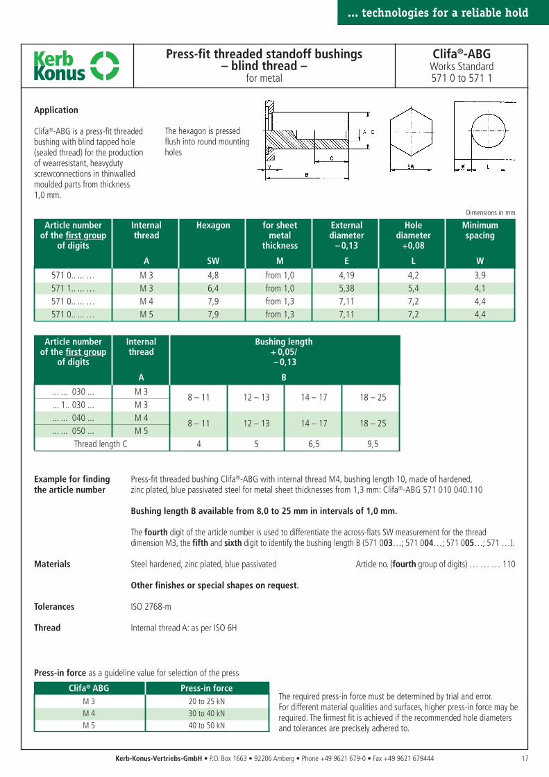
Clifa®-ABG is a press-fit threadedbushing with blind tapped hole(sealed thread) for the productionof wearresistant, heavydutyscrewconnections in thinwalledmoulded parts from thickness1,0 mm.
The hexagon is pressedflush into round mountingholes
Example for finding Press-fit threaded bushing Clifa®-ABG with internal thread M4, bushing length 10, made of hardened,the article number zinc plated, blue passivated steel for metal sheet thicknesses from 1,3 mm: Clifa®-ABG 571 010 040.110
Bushing length B available from 8,0 to 25 mm in intervals of 1,0 mm.
The fourth digit of the article number is used to differentiate the across-flats SW measurement for the thread dimension M3, the fifth and sixth digit to identify the bushing length B (571 003…; 571 004…; 571 005…; 571 …).
Materials Steel hardened, zinc plated, blue passivated Article no. (fourth group of digits) … … … 110
Other finishes or special shapes on request.
Tolerances ISO 2768-m
Thread Internal thread A: as per ISO 6H
The required press-in force must be determined by trial and error. For different material qualities and surfaces, higher press-in force may berequired. The firmest fit is achieved if the recommended hole diametersand tolerances are precisely adhered to.
Press-in force as a guideline value for selection of the press
Article number Internal Hexagon for sheet External Hole Minimumof the first group thread metal diameter diameter spacing
of digits thickness – 0,13 +0,08
A SW M E L W
571 0.. ... … M 3 4,8 from 1,0 4,19 4,2 3,9571 1.. ... … M 3 6,4 from 1,0 5,38 5,4 4,1571 0.. ... … M 4 7,9 from 1,3 7,11 7,2 4,4571 0.. ... … M 5 7,9 from 1,3 7,11 7,2 4,4
Article number Internal Bushing lengthof the first group thread + 0,05/
of digits – 0,13
A B
... ... 030 ... M 38 – 11 12 – 13 14 – 17 18 – 25
... 1.. 030 ... M 3
... ... 040 ... M 48 – 11 12 – 13 14 – 17 18 – 25
... ... 050 ... M 5Thread length C 4 5 6,5 9,5
Dimensions in mm
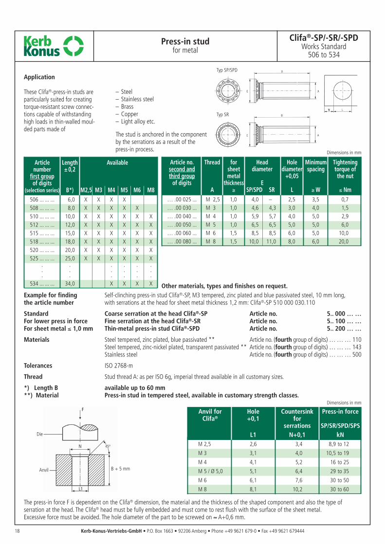
Anvil for Hole Countersink Press-in forceClifa® +0,1 for
serrations SP/SR/SPD/SPSL1 N+0,1 kN
M 2,5 2,6 3,4 8,9 to 12
M 3 3,1 4,0 10,5 to 19
M 4 4,1 5,2 16 to 25
M 5 / Ø 5,0 5,1 6,4 29 to 35
M 6 6,1 7,6 30 to 50
M 8 8,1 10,2 30 to 60
Die
Anvil B + 5 mm
18 Kerb-Konus-Vertriebs-GmbH • P.O. Box 1663 • 92206 Amberg • Phone +49 9621 679-0 • Fax +49 9621 679444
The press-in force F is dependent on the Clifa® dimension, the material and the thickness of the shaped component and also the type ofserration at the head. The Clifa® head must be fully embedded and must come to rest flush with the surface of the sheet metal. Excessive force must be avoided. The hole diameter of the part to be screwed on ≈ A+0,6 mm.
Dimensions in mm
Press-in studfor metal
Clifa®-SP/-SR/-SPDWorks Standard
506 to 534
Typ SP/SPD
Typ SR
Application
These Clifa®-press-in studs areparticularly suited for creatingtorque-resistant screw connec-tions capable of withstandinghigh loads in thin-walled moul-ded parts made of
– Steel– Stainless steel– Brass– Copper– Light alloy etc.
The stud is anchored in the componentby the serrations as a result of thepress-in process.
Example for finding Self-clinching press-in stud Clifa®-SP, M3 tempered, zinc plated and blue passivated steel, 10 mm long,the article number with serrations at the head for sheet metal thickness 1,2 mm: Clifa®-SP 510 000 030.110
Standard Coarse serration at the head Clifa®-SP Article no. 5.. 000 … …For lower press in force Fine serration at the head Clifa®-SR Article no. 5.. 100 … …For sheet metal ≤ 1,0 mm Thin-metal press-in stud Clifa®-SPD Article no. 5.. 200 … …
Materials Steel tempered, zinc plated, blue passivated ** Article no. (fourth group of digits) … … … 110Steel tempered, zinc-nickel plated, transparent passivated ** Article no. (fourth group of digits) … … … 143Stainless steel Article no. (fourth group of digits) … … … 500
Tolerances ISO 2768-m
Thread Stud thread A: as per ISO 6g, imperial thread available in all customary sizes.
*) Length B available up to 60 mm**) Material Press-in stud in tempered steel, available in customary strength classes.
Article no. Thread for Head Hole Minimum Tighteningsecond and sheet diameter diameter spacing torque ofthird group metal +0,05 the nut
of digits thickness EA ≥ SP/SPD SR L ≥ W ≤ Nm
… .00 025 ... M 2,5 1,0 4,0 – 2,5 3,5 0,7… .00 030 ... M 3 1,0 4,6 4,3 3,0 4,0 1,5… .00 040 ... M 4 1,0 5,9 5,7 4,0 5,0 2,9… .00 050 ... M 5 1,0 6,5 6,5 5,0 5,0 6,0… .00 060 ... M 6 1,5 8,5 8,5 6,0 5,0 10,0… .00 080 ... M 8 1,5 10,0 11,0 8,0 6,0 20,0
Dimensions in mm
Other materials, types and finishes on request.
Article Length Availablenumber ± 0,2
first groupof digits
(selection series) B*) M2,5 M3 M4 M5 M6 M8506 ... ... ... 6,0 X X X X508 ... ... ... 8,0 X X X X X510 ... ... ... 10,0 X X X X X X512 ... ... ... 12,0 X X X X X X515 ... ... ... 15,0 X X X X X X518 ... ... ... 18,0 X X X X X X520 ... ... ... 20,0 X X X X X X525 ... ... ... 25,0 X X X X X X
. . . . . .
. . . . . .
. . . . . .534 ... ... ... 34,0 X X X X
19
... technologies for a reliable hold
Dimensions in mm
Kerb-Konus-Vertriebs-GmbH • P.O. Box 1663 • 92206 Amberg • Phone +49 9621 679-0 • Fax +49 9621 679444
Article number Thread Length Head Hole Hole for Minimumdiameter diameter anvil spacing
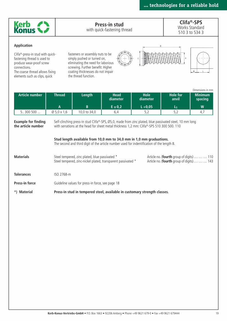
A B E ± 0,2 L +0,05 L1 W5.. 300 500 ... Ø 5,0 x 1,6 10,0 to 34,0 6,4 5,2 5,2 4,7
... technologies for a reliable hold
Press-in studwith quick-fastening thread
Clifa®-SPSWorks Standard510 3 to 534 3
Example for finding Self-clinching press-in stud Clifa®-SPS, Ø5,0, made from zinc plated, blue passivated steel, 10 mm longthe article number with serrations at the head for sheet metal thickness 1,2 mm: Clifa®-SPS 510 300 500. 110
Stud length available from 10,0 mm to 34,0 mm in 1,0 mm graduations.The second and third digit of the article number used for indentification of the length B.
Materials Steel tempered, zinc plated, blue passivated * Article no. (fourth group of digits) … … … 110Steel tempered, zinc-nickel plated, transparent passivated * Article no. (fourth group of digits) … … … 143
Tolerances ISO 2768-m
Press-in force Guideline values for press-in force, see page 18
*) Material Press-in stud in tempered steel, available in customary strength classes.
Application
Clifa®-press-in stud with quick-fastening thread is used toproduce wear-proof screwconnections.The coarse thread allows fixingelements such as clips, quick
fasteners or assembly nuts to besimply pushed or turned on,eliminating the need for laboriousscrewing. Further benefit: Highercoating thicknesses do not impairthe thread function.
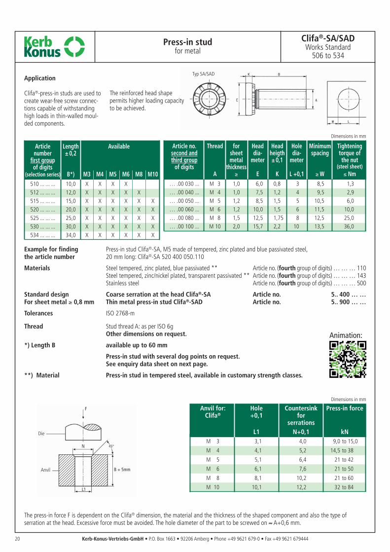
Anvil for: Hole Countersink Press-in forceClifa® +0,1 for
serrationsL1 N+0,1 kN
M 3 3,1 4,0 9,0 to 15,0
M 4 4,1 5,2 14,5 to 38
M 5 5,1 6,4 21 to 42
M 6 6,1 7,6 21 to 50
M 8 8,1 10,2 21 to 60
M 10 10,1 12,2 32 to 84
Article Length Availablenumber ± 0,2
first groupof digits
(selection series) B*) M3 M4 M5 M6 M8 M10510 ... ... ... 10,0 X X X X512 ... ... ... 12,0 X X X X X515 ... ... ... 15,0 X X X X X X520 ... ... ... 20,0 X X X X X X525 ... ... ... 25,0 X X X X X X530 ... ... ... 30,0 X X X X X X534 ... ... ... 34,0 X X X X X X
Example for finding Press-in stud Clifa®-SA, M5 made of tempered, zinc plated and blue passivated steel,the article number 20 mm long: Clifa®-SA 520 400 050.110
Materials Steel tempered, zinc plated, blue passivated ** Article no. (fourth group of digits) … … … 110Steel tempered, zinc/nickel plated, transparent passivated ** Article no. (fourth group of digits) … … … 143Stainless steel Article no. (fourth group of digits) … … … 500
Standard design Coarse serration at the head Clifa®-SA Article no. 5.. 400 … …For sheet metal ≥ 0,8 mm Thin metal press-in stud Clifa®-SAD Article no. 5.. 900 … …
Tolerances ISO 2768-m
Thread Stud thread A: as per ISO 6gOther dimensions on request.
*) Length B available up to 60 mm
Press-in stud with several dog points on request.See enquiry data sheet on next page.
**) Material Press-in stud in tempered steel, available in customary strength classes.
20
Press-in studfor metal
Clifa®-SA/SADWorks Standard
506 to 534
The press-in force F is dependent on the Clifa® dimension, the material and the thickness of the shaped component and also the type ofserration at the head. Excessive force must be avoided. The hole diameter of the part to be screwed on ≈ A+0,6 mm.
Kerb-Konus-Vertriebs-GmbH • P.O. Box 1663 • 92206 Amberg • Phone +49 9621 679-0 • Fax +49 9621 679444
Die
Anvil
Typ SA/SADApplication
Clifa®-press-in studs are used tocreate wear-free screw connec-tions capable of withstandinghigh loads in thin-walled moul-ded components.
The reinforced head shapepermits higher loading capacityto be achieved.
Dimensions in mm
Article no. Thread for Head Head Hole Minimum Tighteningsecond and sheet dia- heigth dia- spacing torque ofthird group metal meter ± 0,1 meter the nut
of digits thickness (steel sheet)A ≥ E K L +0,1 ≥ W ≤ Nm
… .00 030 ... M 3 1,0 6,0 0,8 3 8,5 1,3… .00 040 ... M 4 1,0 7,5 1,2 4 9,5 2,9… .00 050 ... M 5 1,2 8,5 1,5 5 10,5 6,0… .00 060 ... M 6 1,2 10,0 1,5 6 11,5 10,0… .00 080 ... M 8 1,5 12,5 1,75 8 12,5 25,0… .00 100 ... M 10 2,0 15,7 2,2 10 13,5 36,0
Dimensions in mm
Animation:
21
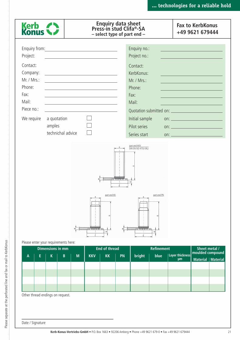
Enquiry data sheetPress-in stud Clifa®-SA– select type of part end –
Fax to KerbKonus+49 9621 679444
Please enter your requirements here:
Other thread endings on request.
Kerb-Konus-Vertriebs-GmbH • P.O. Box 1663 • 92206 Amberg • Phone +49 9621 679-0 • Fax +49 9621 679444
part end KK part end PN
... technologies for a reliable hold
Enquiry from:
Project:
Contact:
Company:
Mr. / Mrs.:
Phone:
Fax:
Mail:
Piece no.:
We require a quotation
amples
technichal advice
Enquiry no.:
Project no.:
Contact:
KerbKonus:
Mr. / Mrs.:
Phone:
Fax:
Mail:
Quotation submitted on:
Initial sample on:
Pilot series on:
Series start on:
Date / Signature
Plea
se s
epar
ate
at th
e pe
rfora
ted
line
and
fax
or m
ail t
o Ke
rbKo
nus
part end KKVDIN EN ISO 4753 (RL)
Dimensions in mm End of thread Refinement Sheet metal /
A E K B M KKV KK PN bright blue Layer thicknessmoulded compound
µm Material Material
22
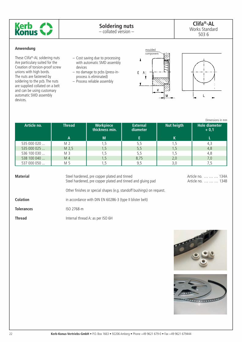
Soldering nuts– collated version –
Clifa®-ALWorks Standard
503 6
Article no. Thread Workpiece External Nut heigth Hole diameterthickness min. diameter + 0,1
A M E K L535 000 020 ... M 2 1,5 5,5 1,5 4,3535 000 025 ... M 2,5 1,5 5,5 1,5 4,8536 100 030 ... M 3 1,5 5,5 1,5 4,8538 100 040 ... M 4 1,5 8,75 2,0 7,0537 000 050 ... M 5 1,5 9,5 3,0 7,5
Dimensions in mm
Kerb-Konus-Vertriebs-GmbH • P.O. Box 1663 • 92206 Amberg • Phone +49 9621 679-0 • Fax +49 9621 679444
Material Steel hardened, pre copper plated and tinned Article no. … … … 134A Steel hardened, pre copper plated and tinned and gluing pad Article no. … … … 134B
Other finishes or special shapes (e.g. standoff bushings) on request.
Colation in accordance with DIN EN 60286-3 (type II blister belt)
Tolerances ISO 2768-m
Thread Internal thread A: as per ISO 6H
Anwendung
These Clifa®-AL soldering nutsAre particulary suited for theCreation of torsion-proof screwunions with high bords.The nuts are fastened bysoldering to the pcb. The nutsare supplied collated on a beltand can be using customaryautomatic SMD assemblydevices.
– Cost saving due to processingwith automatic SMD assemblydevices
– no damage to pcbs (press-in-process is eliminated)
– Process reliable assembly
mouldedcomponent
23
... technologies for a reliable hold
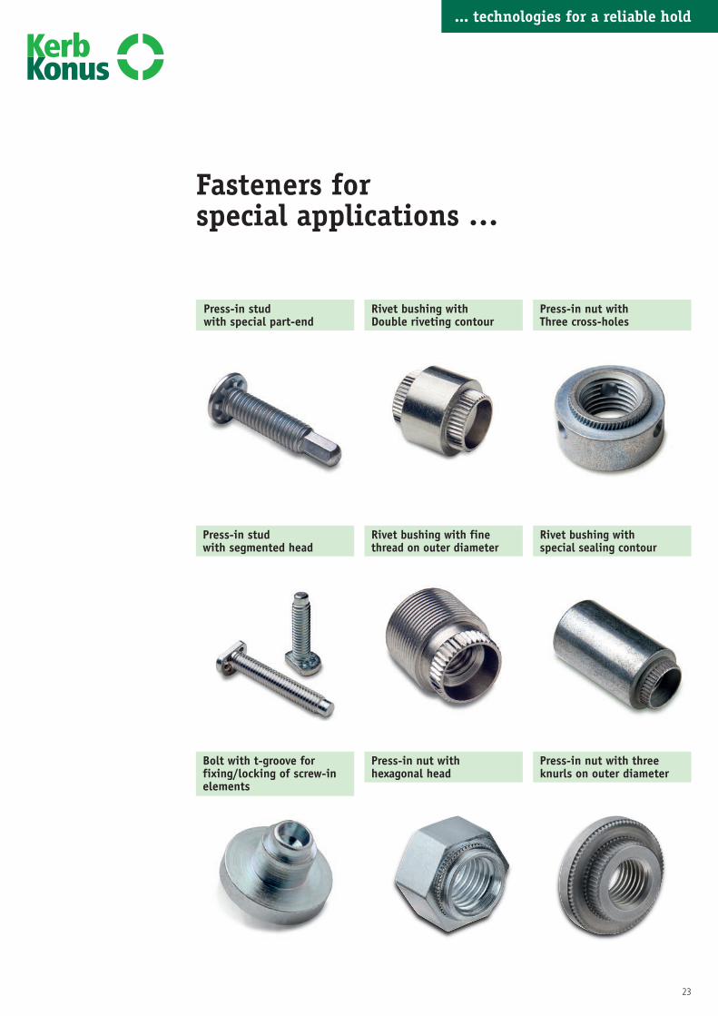
Press-in studwith special part-end
Rivet bushing withDouble riveting contour
Press-in studwith segmented head
Rivet bushing with finethread on outer diameter
Bolt with t-groove forfixing/locking of screw-inelements
Press-in nut withhexagonal head
Fasteners for special applications …
Press-in nut withThree cross-holes
Rivet bushing withspecial sealing contour
Press-in nut with threeknurls on outer diameter
... technologies for a reliable hold
... technologies for a reliable hold
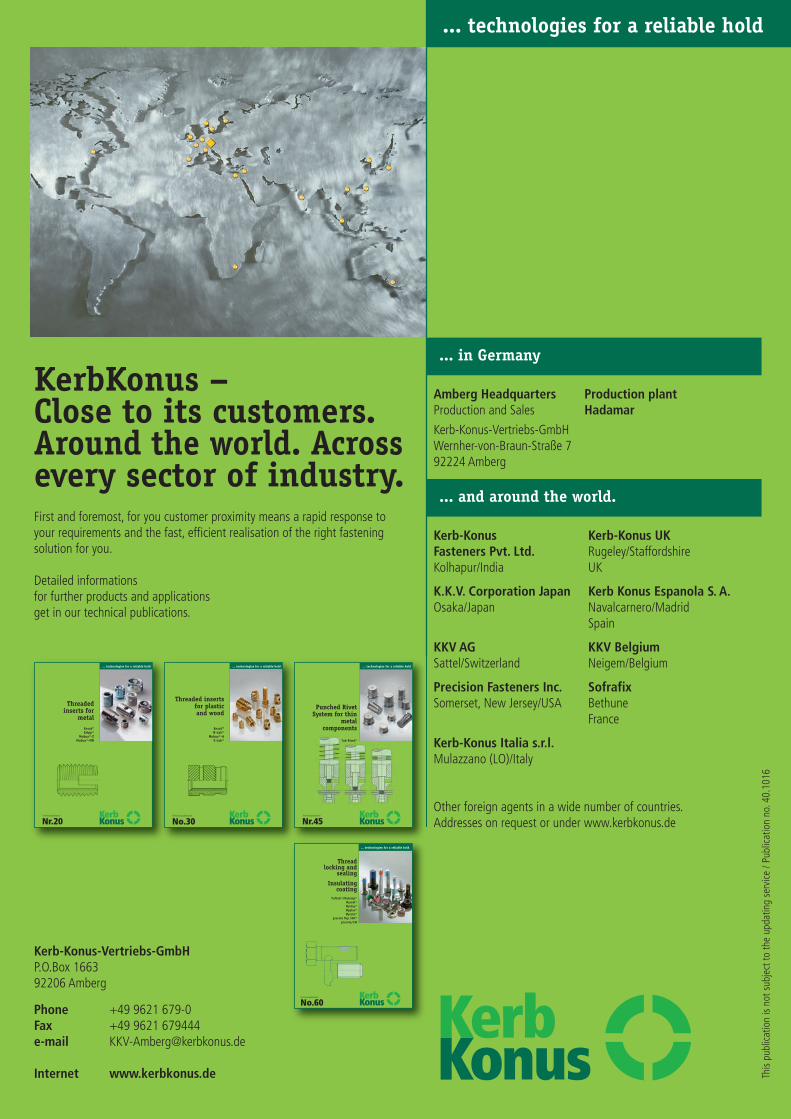
... in Germany
... and around the world.
KerbKonus –Close to its customers.Around the world. Acrossevery sector of industry.First and foremost, for you customer proximity means a rapid response toyour requirements and the fast, efficient realisation of the right fasteningsolution for you.
Detailed informationsfor further products and applicationsget in our technical publications.
Kerb-Konus-Vertriebs-GmbHP.O.Box 166392206 Amberg
Phone +49 9621 679-0Fax +49 9621 679444e-mail [email protected]
Internet www.kerbkonus.de
Amberg Headquarters Production plantProduction and Sales HadamarKerb-Konus-Vertriebs-GmbHWernher-von-Braun-Straße 792224 Amberg
Kerb-Konus Kerb-Konus UKFasteners Pvt. Ltd. Rugeley/StaffordshireKolhapur/India UK
K.K.V. Corporation Japan Kerb Konus Espanola S. A.Osaka/Japan Navalcarnero/Madrid
Spain
KKV AG KKV BelgiumSattel/Switzerland Neigem/Belgium
Precision Fasteners Inc. SofrafixSomerset, New Jersey/USA Bethune
France
Kerb-Konus Italia s.r.l.Mulazzano (LO)/Italy
Other foreign agents in a wide number of countries.Addresses on request or under www.kerbkonus.de
This
publ
icat
ion
is no
t sub
ject
to th
e up
datin
g se
rvic
e / P
ublic
atio
n no
. 40.
1016