Embed Size (px)
Citation preview
SAFETY WARNINGSBEFORE OPERATING OR INSTALLING THIS PUMP, READ THIS MANUAL AND FOLLOW ALL SAFETY RULES AND OPERATING INSTRUCTIONS.
SAFETY CAREFULLY READ THESE SAFETY MESSAGES IN THIS MANUAL AND ON PUMP.
WARNING - ELECTRICAL PRECAUTIONSAll wiring, electrical connections, and system grounding must comply with the National Electrical Code (NEC) and with any local codes and ordinances. Employ a licensed electrician.
WARNING - RISK OF ELECTRICAL SHOCK• Have an electrician provide electrical power to the motor.
• Motor must be grounded and terminal cover in place to reduce electrical shock hazard.
• Keep motor operating area as dry as possible.• Always disconnect power before servicing.• Not investigated for use in swimming pool areas.• FBSEF series is capable of pumping liquid fertilizers. Re-
view all chemical manufacturers safety precautions before handling. Do not breathe or ingest fumes or chemicals.
a) PUMP LOCATION: The pump should be installed in a clean, dry and ventilated location which provides adequate drainage, room for servicing and protection from freezing temperatures. It should be bolted down evenly on a good foundation, preferably concrete, to prevent the development of unnecessary stress. Locating the pump as close as possible to the source of water supply reduces the friction losses in the suction pipe and provides for maximum capacities.
b) SUCTION PIPE: It is recommended that only new clean pipe or hose be used and the size be the same as the pump suction tapping. If the pump is installed any appreciable distance away from the source of water supply, the suction pipe should be increased by one size (this would increase the priming time). The suction pipe must always slope upwards from the water source to the pump to avoid air pockets in the line. In cases where the pump has to be reprimed often and it is not necessary that a lot of water be delivered (e.g. draining seepage from behind a cofferdam),
it is advisable to use a 90° or 45° elbow on the suction line. This enables the pump to prime sooner and also prevents kinking of the hose. In cases where a maximum volume of water is required over a prolonged period of time, the suction line should be led almost horizontally to the pump. Thread compound should be used on all pipe joints and connections should be thoroughly tightened. A strainer should be connected to the bottom end of the suction pipe and it should be well submerged at all times.
c) WIRING: It is recommended that a separate circuit be led from the distribution panel to the pump unit. A properly fused disconnect switch is to be installed in the line, making sure that the correct gauge of cable is used to carry the load. Very long leads will require a larger cable. For all three phase motors a separate manual thermal overload switch or a magnetic starter having the proper size heater elements must be installed. An electrician should be employed to do the wiring.
APPLICATIONThis pump is suitable for installations where the vertical distance from the pump to the water level does not exceed 25 feet. In off-set installations, friction losses in the suction pipe must be
taken into consideration. The FBSEF-series pumps are suitable for transferring liquid fertilizer.
INSTALLATION
CAUTION• DO NOT OPERATE THIS PUMP DRY!• Review instructions before operating.
OPERATION - PRIMING THE PUMP WARNING: DO NOT RUN THE PUMP BEFORE PRIMING IT. THE SEAL AND IMPELLER COULD BE
PERMANENTLY DAMAGED.
a) PRIMING: Remove the priming plug located on the top of the casing and fi ll the pump casing with water. Replace the priming plug.
b) IMPELLER ROTATION: The impeller must rotate in a counter-clockwise direction as seen facing the pump from the front of the casing. In the event of wrong rotation for
FBSE AND FBSEF SERIES Self Priming Centrifugal PumpsOWNER'S MANUAL
electric motor models, refer to the instructions furnished with the motor. The rotation of three phase motors can be changed by interchanging any two lead wires.
c) STARTING THE PUMP: Never operate the pump dry as this may damage the seal. If an exceptionally long suction line is used, the water in the pump casing may become

2
Fig. 1
UnionsGate Valve
Strainer
Check Valve
Suction Line
overheated or vapour locked. Should this occur, either a check valve must be installed in the suction line or the length of the suction pipe must be shortened.
d) DRAINING: Should the pump be subject to freezing tem-peratures, it will be necessary to drain the pumpcompletely. To drain, remove the drain plug located at the bottom of the front face of the pump casing and the priming plug and make sure that the drain hole is not choked. After all the water has been drained, operating the pump for a few seconds will ensure that the impeller is devoid of water (make sure that the suction line is also devoid of water).
7) Reconnect the suction and discharge piping and the electric wiring.
PRECAUTIONSa) No matter what the model of the pump, whenever it is
dismantled and then reassembled, always check to see that the impeller rotates freely within the casing.
b) The electric motor models have a fl inger on the shaft. This fl inger must not be removed.
MAINTENANCE (FBSE) WARNING - ELECTRICAL PRECAUTIONS
All wiring, electrical connections, and system grounding must comply with the National Electrical Code (NEC) and with any local codes and ordinances. Employ a licensed electrician.
WARNING - RISK OF ELECTRICAL SHOCK• Have an electrician provide electrical power to the motor.• Motor must be grounded and terminal cover in place to
reduce electrical shock hazard.• Keep motor operating area as dry as possible.• Always disconnect power before servicing.• Not investigated for use in swimming pool areas.a) LUBRICATION: 1) The pump requires no lubrication. 2) Refer to instructions provided by the motor manufacturer.b) REPLACING MECHANICAL SEAL: (Refer to Fig. 2)Disassembly:
1) Disconnect electric power.2) Drain pump.3) Disconnect piping.4) Remove the bolts from the casing.5) Unscrew the impeller (2) in a counter-clockwise direction.6) Slip the rotating seal (7) off the shaft.7) i) With square fl ange motors, remove the seal plate
from the motor end shell. ii) With 56J frame motors, unbolt the adapter from the
motor face and remove.8) Inspect the ceramic seat (8). If it needs replacing, press
it out of the adapter from the motor end.Reassembly:
1) Clean all parts thoroughly before reassembly.2) Use liquid soap on the rubber cup on the ceramic seat
and push it into the adapter, using thumbs only. Make sure that the smooth surface of the ceramic seat faces outwards.
3) Assemble the adapter to the electric motor or gasoline engine, being very careful so as not to damage the ceramic seat.
4) Use liquid soap on the rotating seal and slip it onto the shaft with the shiny side of the ring towards the ceramic seat. Should a sleeve be present in the model, fi rst slide the rotating seal onto the sleeve and then slide the sleeve (the chamfered end fi rst) onto the shaft. Make sure that the shiny side of the ring on the rotating seal is in contact with the ceramic seat.
5) Screw on the impeller.6) Assemble the casing to the adapter and use a new
gasket (3) and new washers on the bolts.
Fig. 2
FBSE-50, -75, -100, -150, -200 Models (Square Flange)
FBSE-300 Models (56J)
3
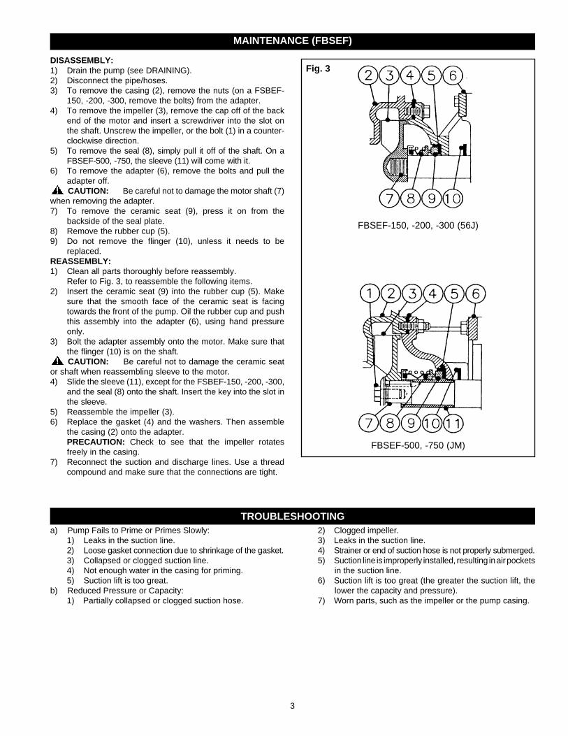
DISASSEMBLY:1) Drain the pump (see DRAINING).2) Disconnect the pipe/hoses.3) To remove the casing (2), remove the nuts (on a FSBEF-
150, -200, -300, remove the bolts) from the adapter.4) To remove the impeller (3), remove the cap off of the back
end of the motor and insert a screwdriver into the slot on the shaft. Unscrew the impeller, or the bolt (1) in a counter-clockwise direction.
5) To remove the seal (8), simply pull it off of the shaft. On a FBSEF-500, -750, the sleeve (11) will come with it.
6) To remove the adapter (6), remove the bolts and pull the adapter off. CAUTION: Be careful not to damage the motor shaft (7)
when removing the adapter.7) To remove the ceramic seat (9), press it on from the
backside of the seal plate.8) Remove the rubber cup (5).9) Do not remove the flinger (10), unless it needs to be
replaced.REASSEMBLY:1) Clean all parts thoroughly before reassembly. Refer to Fig. 3, to reassemble the following items.2) Insert the ceramic seat (9) into the rubber cup (5). Make
sure that the smooth face of the ceramic seat is facing towards the front of the pump. Oil the rubber cup and push this assembly into the adapter (6), using hand pressure only.
3) Bolt the adapter assembly onto the motor. Make sure that the flinger (10) is on the shaft. CAUTION: Be careful not to damage the ceramic seat
or shaft when reassembling sleeve to the motor.4) Slide the sleeve (11), except for the FSBEF-150, -200, -300,
and the seal (8) onto the shaft. Insert the key into the slot in the sleeve.
5) Reassemble the impeller (3).6) Replace the gasket (4) and the washers. Then assemble
the casing (2) onto the adapter. PRECAUTION: Check to see that the impeller rotates
freely in the casing.7) Reconnect the suction and discharge lines. Use a thread
compound and make sure that the connections are tight.
MAINTENANCE (FBSEF)
Fig. 3
FBSEF-500, -750 (JM)
FBSEF-150, -200, -300 (56J)
a) Pump Fails to Prime or Primes Slowly:1) Leaks in the suction line.2) Loose gasket connection due to shrinkage of the gasket.3) Collapsed or clogged suction line.4) Not enough water in the casing for priming.5) Suction lift is too great.
b) Reduced Pressure or Capacity:1) Partially collapsed or clogged suction hose.
2) Clogged impeller.3) Leaks in the suction line.4) Strainer or end of suction hose is not properly submerged.5) Suction line is improperly installed, resulting in air pockets
in the suction line.6) Suction lift is too great (the greater the suction lift, the
lower the capacity and pressure).7) Worn parts, such as the impeller or the pump casing.
TROUBLESHOOTING
4
LIMITED WARRANTY*THIS WARRANTY SETS FORTH THE COMPANY’S SOLE OBLIGATION AND PURCHASER’S EXCLUSIVE REMEDY FOR DEFECTIVE PRODUCT.
Franklin Electric Company, Inc. and its subsidiaries (hereafter “the Company”) warrants that the products accompanied by this warranty are free from defects in material or workmanship of the Company.
The Company has the right to inspect any product returned under warranty to confirm that the product contains a defect in material or workmanship. The Company shall have the sole right to choose whether to repair or replace defective equipment, parts, or components.
The buyer should return the product to the place of purchase for warranty consideration. Subject to the terms and conditions listed below, the Company will repair or replace to the buyer any portion of this product which proves defective due to materials or workmanship of the Company.
The Company will consider products for warranty for 12 months from the date of installation or for 24 months from the date of manufacture, whichever occurs first.
The Company shall IN NO EVENT be responsible or liable for the cost of field labor or other charges incurred by any customer in removing and/or affixing any product, part or component thereof.
The Company reserves the right to change or improve its products or any portions thereof without being obligated to provide such change or improvement to previously sold products.
THIS WARRANTY DOES NOT APPLY TO products damaged by acts of God, including lightning, normal wear and tear, normal maintenance services and the parts used in connection with such service, or any other conditions beyond the control of the Company.
THIS WARRANTY WILL IMMEDIATELY VOID if any of the following conditions arev found:
1. Product is used for purposes other than those for which it was designed and manufactured;2. Product was not installed in accordance with applicable codes, ordinances and good trade practices;3. Product was not installed by a Franklin Certified Contractor or Franklin Key Dealer; or4. Product was damaged as a result of negligence, abuse, accident, misapplication, tampering, alteration, improper installation, operation, maintenance or storage, nor to an excess of recommended maximums as set forth in the product instructions.
NEITHER SELLER NOR THE COMPANY SHALL BE LIABLE FOR ANY INJURY, LOSS OR DAMAGE, DIRECT, INCIDENTAL OR CONSEQUENTIAL (INCLUDING, BUT NOT LIMITED TO, INCIDENTAL OR CONSEQUENTIAL DAMAGES FOR LOST PROFITS, LOST SALES, INJURY TO PERSON OR PROPERTY, OR ANY OTHER INCIDENTAL OR CONSEQUENTIAL LOSS), ARISING OUT OF THE USE OR THE INABILITY TO USE THE PRODUCT, AND THE BUYER AGREES THAT NO OTHER REMEDY SHALL BE AVAILABLE TO IT.
THE WARRANTY AND REMEDY DESCRIBED IN THIS LIMITED WARRANTY IS AN EXCLUSIVE WARRANTY AND REMEDY AND IS IN LIEU OF ANY OTHER WARRANTY OR REMEDY, EXPRESS OR IMPLIED, WHICH OTHER WARRANTIES AND REMEDIES ARE HEREBY EXPRESSLY EXCLUDED, INCLUDING BUT NOT LIMITED TO ANY IMPLIED WARRANTY OF MERCHANTABILITY OR FITNESS FOR A PARTICULAR PURPOSE, TO THE EXTENT EITHER APPLIES TO A PRODUCT SHALL BE LIMITED IN DURATION TO THE PERIODS OF THE EXPRESSED WARRANTIES GIVEN ABOVE.
DISCLAIMER: Any oral statements about the product made by the seller, the Company, the representatives or any other parties, do not constitute warranties, shall not be relied upon by the buyer, and are not part of the contract for sale. Seller’s and the Company’s only obligation, and buyer’s only remedy, shall be the replacement and/or repair by the Company of the product as described above. Before using, the user shall determine the suitability of the product for his intended use, and user assumes all risk and liability whatsoever in connection therewith.
Some states and countries do not allow the exclusion or limitations on how long an implied warranty lasts or the exclusion or limitation of incidental or consequential damages, so the above exclusion or limitations may not apply to you. This warranty gives you specific legal rights, and you may also have other rights which vary from state to state and country to country.
*Contact Franklin Electric Co., Inc. Export Division for International Warranty.
400 E. Spring StreetBluffton, IN 46714Tel: 260-824-2900Fax: 260-824 2909www.franklin-electric.com

5
CONSIGNES DE SÉCURITÉAVA N T D ' I N S TA L L E R O U D'UTILISER CETTE POMPE, PRIÈRE DE LIRE LE PRÉSENT GUIDE ET SUIVRE TOUTES LES RÈGLES DE SÉCURITÉ ET INSTRUCTIONS D'UTILISATION.
SÉCURITÉ LIRE ATTENTIVEMENT LES AVIS DE SÉCU-RITÉ SE TROUVANT DANS LE PRÉSENT MANUEL ET SUR LA POMPE.
AVERTISSEMENT- PRÉCAUTIONS ÉLECTRIQUESTous câblage, connexions électriques et mise à la terre des systémes doivent se conformer au Code National d'Electricité (NEC) et aux codes et ordonnances locaux. Employez un électricien autorisé.
AVERTISSEMENT - RISQUE DE CHOC ÉLECTRIQUE• Faire appel à un électricien pour l’alimentation électrique du
moteur.
• Le moteur doit être mis à la terre et le couvercle des bornes correctement installé afi n de réduire les risques d’électrocution.
• Garder la zone de travail aussi sèche que possible.• Toujours couper l’alimentation avant de procéder à
l’entretien.• Cette pompe n’est pas conçue pour être utilisée dans la
région d'une piscine.• Les pompes de la série FBSEF sont aptes au transfert de
l'engrais liquide. Examiner toutes les précautions de la sécurité chimique fabricants avant de les manipuler. Ne pas respirer ou ingérer des vapeurs ou des produits chimiques.
UTILISATION
INSTALLATIONa) EMPLACEMENT DE LA POMPE : Il est conseillé d’installer
la pompe dans un endroit propre, sec et aéré offrant un bon drainage, de l’espace pour l’entretien et une protec-tion contre le gel. Il faudrait la boulonner bien à plat à une assise solide, de préférence en béton, afi n de prévenir les contraintes inutiles. Pour réduire les pertes de charge dans la conduite d’aspiration et obtenir le débit maximal, rapprocher le plus possible la pompe de l’eau à pomper.
b) CONDUITE D’ASPIRATION : Il est recommandé d’utiliser un tuyau ou un boyau neuf et propre dont le diamètre est égal au taraudage de l’orifi ce d’aspiration. Si la pompe se trouve à une distance assez importante de la source d’alimentation en eau, le diamètre de la conduite d’aspiration devrait être plus grand. (ce qui augmenterait la période d’amorçage). La conduite d’aspiration doit toujours être placée en pente ascendante à partir de la source d’eau vers la pompe, pour éviter la formation de poches d’air dans la conduite. Dans les cas où la pompe doit être réamorcée souvent et qu’un grand débit d’eau n’est pas nécessaire (ex : l’extrémité biseautée en premier), il est conseillé d’utiliser un coude
de 90° ou de 45° dans la conduite d’aspiration. L’amorçage peut ainsi se faire plus rapidement et prévenir le tortille-ment du boyau. Si un volume d’eau important est requis pendant une période prolongée, la conduite d’aspiration devrait être aussi à l’horizontale que possible par rapport à la pompe. Il est également conseillé d’enduire les joints et les raccords de tuyau, d’une graisse pour fi letage non toxique et de bien les serrer. L’extrémité inférieure de la conduite d’aspiration devrait être munie d’une crépine immergée en tout temps.
c) CÂBLAGE : Il est recommandé qu’un circuit séparé soit installé du tableau de distribution jusqu’à la pompe. Un sectionneur à fusible doit être installé sur la ligne. Munir ce circuit du sectionneur à fusible approprié et choisir des fi ls de calibre qui conviennent à l’installation. Les conduc-teurs d’une longueur exceptionnelle exigent un fi lage plus gros. On doit doter les moteurs triphasés d’un disjoncteur de surcharge manuel distinct ou d’un démarreur magné-tique munis des éléments chauffants adéquats. Toujours employer un électricien pour faire le branchement.
Cette pompe convient aux installations dont la distance verticale entre la pompe et l’eau à pomper ne dépasse pas 25 pieds. Dans le cas des installations décalées, il faut tenir compte des pertes
de charge dans la conduite d’aspiration. Les pompes de la série FBSEF sont aptes au transfert de l'engrais liquide.
CAUTION• NE PAS FAIRE FONCTIONNER CETTE POMPE À SEC!• Passez les instructions en revue avant d’utiliser la pompe.
FONCTIONNEMENT - AMORÇAGE DE LA POMPE
a) AMORÇAGE : Pour amorcer la pompe, il faut enlever le bouchon d’amorçage se trouvant sur le dessus du boîtier, remplir le boîtier d’eau et remettre le bouchon en place.
AVERTISSEMENT : DE NE PAS FAIRE FONCTIONNER LA POMPE À SEC AVANT L’AMORÇAGE, SINON LE JOINT D’ÉTANCHÉITÉ ET LA ROUE DE TURBINE SERAIENT ENDOMMAGÉS DE FAÇON PERMANENTE.
b) ROTATION DE LA ROUE : La roue doit tourner dans le sens des aiguilles d’une montre si l’on se place devant la pompe, face au boîtier. Pour ce qui est des modèles avec moteur électrique, si la
SÉRIE FBSE ET FBSEF Pompes centrifuges à amorçage automatiqueMANUEL DU PROPRIÉTAIRE
6
ENTRETIEN (FBSE)
Fig. 2
Modèles FBSE-50, -75, -100, -150, -200 (Bride Carrée)
Modèle FBSE-300 (56J)
Fig. 1
Robinet-vanne
Crépine
Clapet de retenue
Conduite d’aspiration
Raccord-union
AVERTISSEMENT - PRÉCAUTIONS ÉLECTRIQUESTous câblage, connexions électriques et mise à la terre des systémes doivent se conformer au Code National d'Electricité (NEC) et aux codes et ordonnances locaux. Employez un électricien autorisé.
AVERTISSEMENT - RISQUE DE CHOC ÉLECTRIQUE• Faire appel à un électricien pour l’alimentation électrique
du moteur.• Le moteur doit être mis à la terre et le couvercle des
bornes correctement installé afi n de réduire les risques d’électrocution.
• Garder la zone de travail aussi sèche que possible.• Toujours couper l’alimentation avant de procéder à
l’entretien.• Cette pompe n’est pas conçue pour être utilisée dans la
région d'une piscine.a) LUBRIFICATION : 1) Cette pompe n’exige aucune lubrifi cation. 2) Voir les instructions fournies par le fabricant du moteur.b) REMPLACEMENT DE LA GARNITURE D’ÉTANCHÉITÉ
MÉCANIQUE : (voir la Fig. 2)Démontage :
1) Débrancher le cordon électrique.2) Vidanger la pompe.3) Débrancher les conduites d'aspiration et de refoulement.4) Retirer les boulons du boîtier.5) Dévisser la roue (2) dans le sens contraire des aiguilles
d’une montre.6) Faire glisser la garniture d’étanchéité mécanique (7)
hors de l’arbre.7) i) Pour les moteurs à bride carrée, retirer la plaque
d’étanchéité du carter de l’arbre moteur. ii) Pour les moteurs à bâti 56J, déboulonner et
enlever l’adaptateur du moteur.8) Examiner l’embase de céramique (8). S’il faut la remplacer,
l’enlever de l’adaptateur en appuyant sur l’arbre moteur.Remontage :
1) Bien nettoyer toutes les pièces avant le remontage.2) Utiliser un savon liquide sur la cuvette de caoutchouc de
l’embase de céramique et l’insérer dans l’adaptateur avec les pouces. S’assurer que la surface polie donne vers l’extérieur.
3) Monter l’adaptateur sur le moteur à essence ou le moteur électrique en prenant bien soin de na pas endommager l’embase de céramique.
4) Utiliser un savon liquide sur la garniture mécanique et la faire glisser sur l’arbre moteur, la rondelle polie orientée en direction de l’embase de céramique Si la pompe est munie d’un manchon, assembler d’abord la garniture
roue tourne dans le mauvais sens, consulter le mode d’emploi qui accompagne le moteur. Il est possible de modifi er la rotation des moteurs triphasés en inversant deux conducteurs.
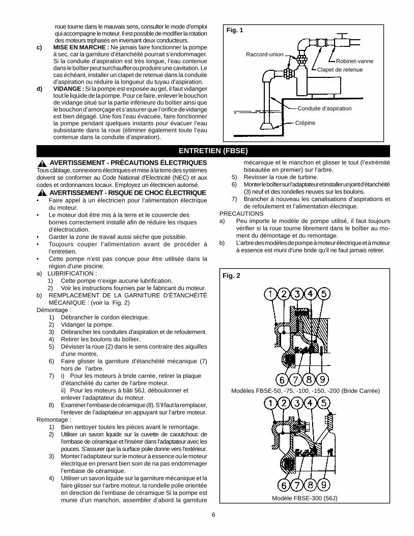
c) MISE EN MARCHE : Ne jamais faire fonctionner la pompe à sec, car la garniture d’étanchéité pourrait s’endommager. Si la conduite d’aspiration est très longue, l’eau contenue dans le boîtier peut surchauffer ou produire une cavitation. Le cas échéant, installer un clapet de retenue dans la conduite d’aspiration ou réduire la longueur du tuyau d’aspiration.
d) VIDANGE : Si la pompe est exposée au gel, il faut vidanger tout le liquide de la pompe. Pour ce faire, enlever le bouchon de vidange situé sur la partie inférieure du boîtier ainsi que le bouchon d’amorçage et s’assurer que l’orifi ce de vidange est bien dégagé. Une fois l’eau évacuée, faire fonctionner la pompe pendant quelques instants pour évacuer l’eau subsistante dans la roue (éliminer également toute l’eau contenue dans la conduite d’aspiration).
mécanique et le manchon et glisser le tout (l’extrémité biseautée en premier) sur l’arbre.
5) Revisser la roue de turbine.6) Monter le boîtier sur l’adaptateur et installer un joint d’étanchéité
(3) neuf et des rondelles neuves sur les boulons.7) Brancher à nouveau les canalisations d’aspirations et
de refoulement et l’alimentation électrique.PRECAUTIONSa) Peu importe le modèle de pompe utilisé, il faut toujours
vérifi er si la roue tourne librement dans le boîtier au mo-ment du démontage et du remontage.
b) L’arbre des modèles de pompe à moteur électrique et à moteur à essence est muni d’une bride qu’il ne faut jamais retirer.

7
DÉMONTAGE :1) Vidanger la pompe (voir la section «Vidange»).2) Détacher le tuyau ou le boyau.3) Pour retirer le boîtier (2), enlever les écrous de l'adaptateur
(modèle FBSEF-500, -750, enlever les boulons).4) Pour retirer la roue de turbine (3), enlever le couvercle de
l'extrémité arrière du moteur et insérer un tournevis dans l'encoche de l'arbre. Faire tourner la roue de turbine ou le boulon (1) dans le sens contraire des aiguilles d'une montre.
5) Pour enlever le joint (8), le tirer simplement de l'arbre. Sur les modèles FBSEF-500, -750, le manchon (11) s'enlèvera en même temps.
6) Pour enlever l'adaptateur (6), il suffit de le tirer après avoir enlevè les boulons. MISE EN GARDE : Faire attention de ne pas endommager
l'arbre du moteur (7) en enlevant l'adaptateur.7) Pour retirer le siège de céramique (9), appuyer à l'arrière
de la plaque d'étanchéité.8) Enlever le bouchon de caoutchouc (5).9) Ne pas enlever le cavalier (10) sauf s'il faut le remplacer.MONTAGE :1) Nettoyer soigneusement toutes les pièces avant de les
remonter. Consulter la fig. 3 pour remonter les articles suivants
2) Insérer le siège de céramique (9) dans le bouchon de caoutchouc (5). S'assurer que la surface lisse du siège de céramique est orientée vers l'avant de la pompe. Huiler le bouchon de caoutchouc et insérer l'ensemble dans l'adaptateur (6) d'étanchéité en exerçant une pression avec la main.
3) Fixer l'adaptateur au moteur. S'assurer que le cavalier (10) est installé sur l'arbre. MISE EN GARDE : Faire attention de ne pas
endommager le siège de céramique ou l'arbre en fixant le manchon au moteur.4) Faire glisser le manchon (11), et le joint (8) sur l'arbre (sauf
sur le modèle FSBEF-150, -200, -300). Insérer la clé dans l'encoche du manchon.
5) Remonter la roue de turbine (3).6) Replacer le joint d'étanchéité (4) et les rondelles. Fixer
ensuite le boîtier (2) à l'adaptateur. PRÉCAUTION : Vérifier si la roue de turbine tourne
librement dans le boîtier.7) Raccorder les conduites d'aspiration et de refoulement.
Appliquer un produit d'étanchéité sur les filets et s'assurer que les raccords sont bien serrés.
ENTRETIEN (FBSEF)
a) Problèmes d’amorçage :1) Fuites dans la conduite d’aspiration.2) Mauvaise étanchéité du joint en raison de sa contraction.3) Conduite d’aspiration affaissée ou obstruée.4) Quantité d’eau insuffi sante d’eau dans le boîtier pour
permettre l’amorçage.5) Hauteur géométrique d’aspiration trop élevée.
b) Perte de pression ou de débit :1) Conduite d’aspiration en partie affaissée ou obstruée.2) Roue de turbine obstruée.
3) Fuites dans la conduite d’aspiration.4) Immersion incomplète de la crépine ou de l’extrémité
de la conduite d’aspiration.5) Mauvaise installation de la conduite d’aspiration provo-
quant la formation de poches d’air dans la conduite.6) Hauteur géométrique d’aspiration trop élevée (une hau-
teur géométrique d’aspiration élevée réduit d’autant le débit de la pression).
7) Usure de certaines pièces, comme la roue de turbine ou le boîtier de la pompe.
LES PROBLÈMES ET LEURS CAUSES
Fig. 3
FBSEF-500, -750 (JM)
FBSEF-150, -200, -300 (56J)

8
GARANTIE LIMITÉE*LA PRÉSENTE GARANTIE ÉTABLIT LA SEULE OBLIGATION DE LA SOCIÉTÉ ET LE RECOURS EXCLUSIF DE L’ACHETEUR EN CE QUI A TRAIT À UN PRODUIT DÉFECTUEUX.
Franklin Electric Company, Inc. et ses filiales (ci-après « la Société ») garantissent que les produits accompagnés de la présente garantie sont exempts de défauts de matériel et de main-d’œuvre liés à la Société. La Société a le droit d’inspecter tout produit renvoyé sous garantie pour confirmer que ledit produit contient un défaut de matériel ou de main-d’œuvre. La Société aura le droit exclusif de choisir de réparer ou de remplacer les équipements, pièces ou composants défectueux. L’acheteur devra renvoyer le produit au point d’achat pour qu’il soit pris en compte par la garantie. Sous réserve des conditions et modalités énumérées ci-dessous, la Société réparera ou remplacera toute partie de ce produit qui s’avère défectueuse pour des raisons de matériel ou de main-d’œuvre liés à la Société. La Société considérera les produits pour garantie pendant 12 mois à compter de la date d’installation ou pendant 24 mois à compter de la date de fabrication, en fonction duquel se passe en premier. EN AUCUN CAS la Société ne sera responsable du coût de la main-d’œuvre extérieure ou d’autres dépenses encourues par tout client afin d’enlever et/ou d’installer tout produit, partie ou composant de ce dernier. La Société se réserve le droit de modifier ou d’améliorer ses produits ou toute partie de ceux-ci sans que cela n’entraîne l’obligation d’apporter ces modifications ou améliorations à des produits préalablement vendus. LA PRÉSENTE GARANTIE NE S’APPLIQUE PAS À des produits endommagés par des catastrophes naturelles, dont la foudre, l’usure normale, le service d’entretien normal et les pièces utilisées en relation avec ledit service, ou toute autre circonstance échappant au contrôle de la Société. LA PRÉSENTE GARANTIE SERA ANNULÉE IMMÉDIATEMENT si l’une ou l’autre des conditions suivantes est présente : 1. Le produit est utilisé à des fins autres que celles pour lesquelles il a été conçu et fabriqué; 2. Le produit n’a pas été installé conformément aux codes et arrêtés applicables et aux bonnes pratiques commerciales; 3. Le produit n’a pas été installé par un Entrepreneur Certifié de Franklin ou Programme pour installateurs clés ; ou4. Le produit a été endommagé pour cause de négligence, d’abus, d’accident, de mauvaise application, d’altération, de procédures
d’installation, d’opération, d’entretien ou d’entreposage non conformes, ou pour cause d’utilisation excédant les maximums recommandés tel que stipulé dans les instructions concernant le produit.
NI LE VENDEUR NI LA SOCIÉTÉ N’ASSUMERONT DE RESPONSABILITÉ POUR TOUTE BLESSURE, TOUTE PERTE OU TOUT DOMMAGE, DIRECT, ACCESSOIRE OU CONSÉCUTIF (Y COMPRIS, MAIS SANS S’Y LIMITER, LES DOMMAGES ACCESSOIRES OU CONSÉCUTIFS POUR PERTE DE BÉNÉFICES, PERTE DE VENTES, BLESSURES À LA PERSONNE OU DÉGÂTS AUX BIENS, OU TOUTE AUTRE PERTE ACCESSOIRE OU CONSÉCUTIVE), DÉCOULANT DE L’UTILISATION OU DE L’INCAPACITÉ D’UTILISER LE PRODUIT, ET L’ACHETEUR ADMET QU’AUCUN AUTRE RECOURS NE SERA DISPONIBLE À CET EFFET. LA GARANTIE ET LE RECOURS DÉCRITS DANS LA PRÉSENTE GARANTIE LIMITÉE SONT UNE GARANTIE ET UN RECOURS EXCLUSIFS, EN LIEU ET PLACE DE TOUT AUTRE GARANTIE OU RECOURS, EXPLICITE OU IMPLICITE, CELA EXCLUANT EXPRESSÉMENT PAR LES PRÉSENTES D’AUTRES GARANTIES ET RECOURS, Y COMPRIS, MAIS SANS S’Y LIMITER, TOUTE GARANTIE IMPLICITE DE MARCHANDISAGE OU D’ADÉQUATION À UNE FIN PARTICULIÈRE, DANS LA MESURE OÙ L’UNE OU L’AUTRE S’APPLIQUE À UN PRODUIT ET SA DURÉE SERA LIMITÉE AUX PÉRIODES DES GARANTIES EXPRESSES INDIQUÉES PLUS HAUT. CLAUSE DE NON-GARANTIE : Toute déclaration orale au sujet du produit faite par le vendeur, la Société, les représentants ou toute autre partie, ne constitue pas une garantie, ne sera pas prise comme référence par l’acheteur et ne fait pas partie du contrat de vente. La seule obligation du vendeur et de la Société ainsi que le recours exclusif de l’acheteur porteront sur le remplacement et/ou la réparation par la Société du produit tel que décrit plus haut. Avant d’utiliser le produit, l’utilisateur devra déterminer l’adéquation dudit produit à l’usage prévu, et l’utilisateur assumera tous les risques et responsabilités afférents, quels qu’ils soient. Certains États et pays n’autorisent pas l’exclusion ou la restriction de la durée d’une garantie implicite ou l’exclusion ou la restriction des dommages accessoires ou consécutifs. Par conséquent, les exclusions ou restrictions susmentionnées pourraient ne pas s’appliquer dans votre cas. La présente garantie vous accorde des droits légaux spécifiques et il se peut que vous puissiez bénéficier d’autres droits qui varient d’un État à l’autre et d’un pays à l’autre. *Communiquez avec le service de l’exportation de Franklin Electric Co., Inc. pour obtenir des informations concernant la garantie internationale.
400 E. Spring StreetBluffton, IN 46714Tel: 260-824-2900Fax: 260-824 2909www.franklin-electric.com

9
• Mantenga el área de operación del motor lo más seca posible.• Desconecte siempre el suministro eléctrico antes de darle
servicio.• No se ha investigado su uso para el área de piscinas.
Las bombas de la serie FBSEF son adecuados para la transferencia de fertilizante líquido. Revise todos los fabricantes de productos químicos precauciones de seguridad antes de manejar. No respirar o ingerir humos o productos químicos.
•
APLICACIÓN
a) UBICACIÓN DE LA BOMBA: Instale la bomba en un lugar limpio, seco y ventilado, con drenaje adecuado, sufi ciente espacio para darle servicio y protegida contra temperaturas congelantes. Se le debe empernar a unos buenos cimientos, de preferencia de concreto, para evitar cualquier tensión innecesaria. El ubicar la bomba lo más cerca posible de la fuente de agua reducirá las pérdidas por fricción en la tubería de succión y proporcionará las capacidades máximas.
b) TUBERÍA DE SUCCIÓN: Se recomienda se utilice sola-mente tuberías o mangueras nuevas y limpias y del mismo tamaño que la toma de succión de la bomba. Si la tubería de succión es larga, aumente un tamaño (esto aumentará el tiempo de cargado). Incline la tubería de succión hacia arriba para evitar bolsas de aire en la misma. En casos en los que se tenga que cargar la bomba frecuentemente y donde no se necesite bombear grandes cantidades de agua (ej: drenado de fi ltración por detrás de una ataquía), se recomienda se use un codo de 90° o 45° en la línea
de succión. Esto le permite a la bomba cargarse más rápidamente y también evita que la manguera se pliegue. En los casos en que se necesite un volumen máximo de agua por largos períodos de tiempo, la línea de succión debe estar casi horizontal con la bomba. Utilice un sellador para rosca en todas las uniones de las tuberías, y las conexiones deben estar bien ajustadas. Se debe conectar un fi ltro o colador en el extremo de la tubería de succión y debe estar bien sumergido en todo momento.
c) CABLEADO: Se recomienda se use un circuito sepa-rado desde el panel de distribución hasta la bomba. Se debe instalar un interruptor de desconexión con fusible adecuado en la línea, asegurándose se use el calibre de cable adecuado para llevar la carga. Los cables muy largos tendrán que ser de mayor calibre. Para los motores trifásicos se debe instalar un interruptor manual de sobre-carga térmica o un arrancador magnético por separado con los elementos térmicos del tamaño correcto. Se debe contratar a un electricista para que haga el cableado.
ADVERTENCIAS DE SEGURIDAD
LEA ESTE MANUAL Y SIGA TODAS LAS REGLAS DE SEGURIDAD ANTES DE INSTALAR U OPERAR ESTA BOMBA.
SEGURIDAD LEA CUIDADOSAMENTE ESTOS MENSAJES DE SEGURIDAD EN ESTE MANUAL Y EN LA BOMBA.
ADVERTENCIA - PRECAUCIONES ELÉCTRICASTodo cableado, conexiones eléctricas y sistemas de contacto a tierra deben cumplir con el Código Eléctrico Nacional (NEC) y con cualquier código y ordenanza local. Contrate los servicios de un electricista con licencia.
ADVERTENCIA - RIESGO DE DESCARGA ELÉCTRICA• Haga que un electricista conecte la electricidad al motor.• El motor debe estar conectado a tierra y la tapa del terminal debe
estar puesta para reducir el peligro de descarga eléctrica.
Utilice estas bombas para aplicaciones donde la distancia verti-cal desde la bomba hasta el nivel del agua no sea mayor de 25 pies (8 metros). Si la bomba está instalada a desnivel, se debe
tomar en consideración la pérdida por fricción en las tuberías de succión. Las bombas de la serie FBSEF son adecuados para la transferencia de fertilizante líquido.
INSTALACIÓN
CUIDADO• ¡NO HAGA FUNCIONAR LA BOMBA EN SECO!• Revise cuidadosamente las instrucciones antes de usarla.
FUNCIONAMIENTO - CÓMO CARGAR LA BOMBA
a) CARGADO: Quite el tapón de cargado ubicado en la parte superior del cuerpo de la bomba y llene el cuerpo de la bomba con agua. Vuelva a colocar el tapón de cargado.
b) ROTACIÓN DEL PROPULSOR: El propulsor debe girar en sentido contrario a las manecillas del reloj cuando se ve la
AVISO: NO OPERAR LA BOMBA ANTES DE CARGARLA, EL SELLO Y EL PROPULSOR PODRÍAN DAÑARSE PERMANENTEMENTE.bomba desde el frente del cuerpo de la misma. En caso de que el propulsor gire en la dirección contraria en los modelos de motores eléctricos, vea las instrucciones proporcionadas con el motor. La rotación de los motores trifásicos se puede cambiar intercambiando dos de los cables, cualquiera de ellos.
SERIE FBSE Y FBSEF Bombas Centrífugas de AutocargadoMANUAL DEL PROPIETARIO
10
MANTENIMIENTO (FBSE)
ADVERTENCIA - PRECAUCIONES ELÉCTRICASTodo cableado, conexiones eléctricas y sistemas de contacto a tierra deben cumplir con el Código Eléctrico Nacional (NEC) y con cualquier código y ordenanza local. Contrate los servicios de un electricista con licencia.
ADVERTENCIA - RIESGO DE DESCARGA ELÉCTRICA• Haga que un electricista conecte la electricidad al motor.• El motor debe estar conectado a tierra y la tapa del terminal
debe estar puesta para reducir el peligro de descarga eléctrica.• Mantenga el área de operación del motor lo más seca posible.• Desconecte siempre el suministro eléctrico antes de darle
servicio.• No se ha investigado su uso para el área de piscinas.a) LUBRICACIÓN:
1) La bomba no necesita lubricación.2) Vea las instrucciones proporcionadas por el fabricante
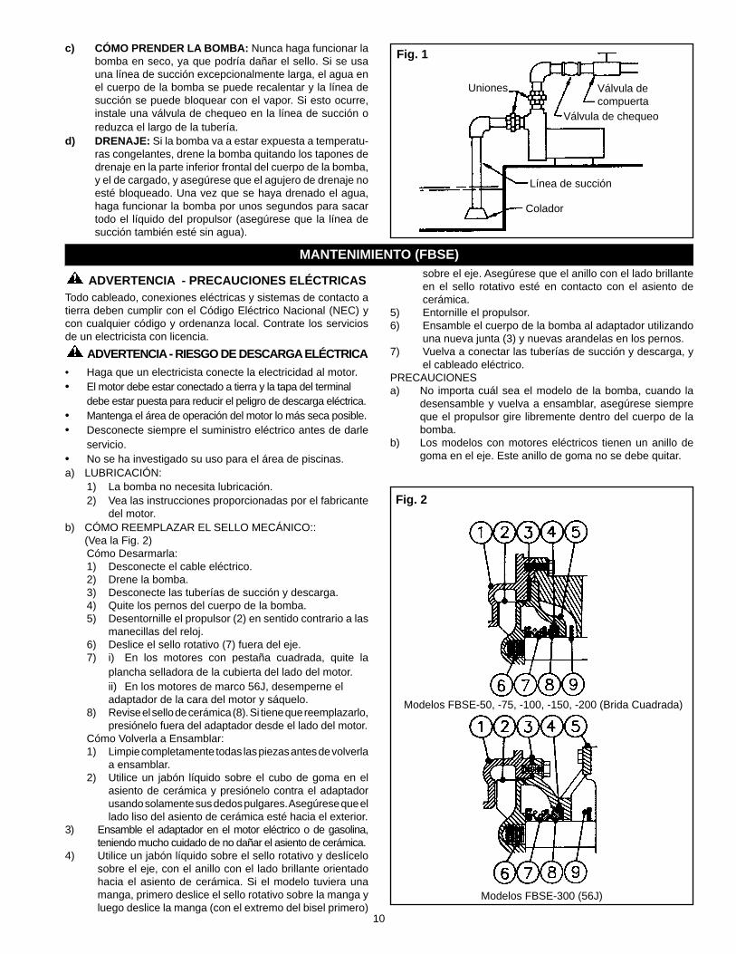
del motor.b) CÓMO REEMPLAZAR EL SELLO MECÁNICO:: (Vea la Fig. 2)
Cómo Desarmarla:1) Desconecte el cable eléctrico.2) Drene la bomba.3) Desconecte las tuberías de succión y descarga.4) Quite los pernos del cuerpo de la bomba.5) Desentornille el propulsor (2) en sentido contrario a las
manecillas del reloj.6) Deslice el sello rotativo (7) fuera del eje.7) i) En los motores con pestaña cuadrada, quite la
plancha selladora de la cubierta del lado del motor. ii) En los motores de marco 56J, desemperne el
adaptador de la cara del motor y sáquelo.8) Revise el sello de cerámica (8). Si tiene que reemplazarlo,
presiónelo fuera del adaptador desde el lado del motor.Cómo Volverla a Ensamblar:1) Limpie completamente todas las piezas antes de volverla
a ensamblar.2) Utilice un jabón líquido sobre el cubo de goma en el
asiento de cerámica y presiónelo contra el adaptador usando solamente sus dedos pulgares. Asegúrese que el lado liso del asiento de cerámica esté hacia el exterior.
3) Ensamble el adaptador en el motor eléctrico o de gasolina, teniendo mucho cuidado de no dañar el asiento de cerámica.
4) Utilice un jabón líquido sobre el sello rotativo y deslícelo sobre el eje, con el anillo con el lado brillante orientado hacia el asiento de cerámica. Si el modelo tuviera una manga, primero deslice el sello rotativo sobre la manga y luego deslice la manga (con el extremo del bisel primero)
Fig. 1
Colador
Válvula de chequeo
Línea de succión
Válvula de compuerta
Uniones
c) CÓMO PRENDER LA BOMBA: Nunca haga funcionar la bomba en seco, ya que podría dañar el sello. Si se usa una línea de succión excepcionalmente larga, el agua en el cuerpo de la bomba se puede recalentar y la línea de succión se puede bloquear con el vapor. Si esto ocurre, instale una válvula de chequeo en la línea de succión o reduzca el largo de la tubería.
d) DRENAJE: Si la bomba va a estar expuesta a temperatu-ras congelantes, drene la bomba quitando los tapones de drenaje en la parte inferior frontal del cuerpo de la bomba, y el de cargado, y asegúrese que el agujero de drenaje no esté bloqueado. Una vez que se haya drenado el agua, haga funcionar la bomba por unos segundos para sacar todo el líquido del propulsor (asegúrese que la línea de succión también esté sin agua).
sobre el eje. Asegúrese que el anillo con el lado brillante en el sello rotativo esté en contacto con el asiento de cerámica.
5) Entornille el propulsor.6) Ensamble el cuerpo de la bomba al adaptador utilizando
una nueva junta (3) y nuevas arandelas en los pernos.7) Vuelva a conectar las tuberías de succión y descarga, y
el cableado eléctrico.PRECAUCIONESa) No importa cuál sea el modelo de la bomba, cuando la
desensamble y vuelva a ensamblar, asegúrese siempre que el propulsor gire libremente dentro del cuerpo de la bomba.
b) Los modelos con motores eléctricos tienen un anillo de goma en el eje. Este anillo de goma no se debe quitar.
Fig. 2
Modelos FBSE-50, -75, -100, -150, -200 (Brida Cuadrada)
Modelos FBSE-300 (56J)
11
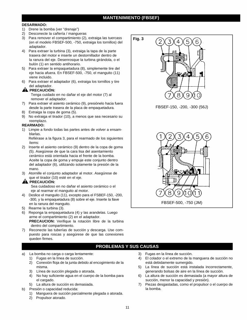
DESARMADO: 1) Drene la bomba (ver “drenaje”)2) Desconecte la cañería / mangueras3) Para remover el compartimiento (2), extraiga las tuercass
(en el modelo FBSEF-500, -750, extraiga los tornillos) del adaptador.
4) Para extraer la turbina (3), extraiga la tapa de la parte trasera del motor e inserte un destornillador dentro de la ranura del eje. Desenrosque la turbina girándola, o el bulón (1) en sentido antihorario.
5) Para extraer la empaquetadura (8), simplemente tire del eje hacia afuera. En FBSEF-500, -750, el manguito (11) viene incluido.
6) Para extraer el adaptador (6), extraiga los tornillos y tire del adaptador. PRECAUCIÓN:
Tenga cuidado en no dañar el eje del motor (7) al remover el adaptador.
7) Para extraer el asiento cerámico (9), presiónelo hacia fuera desde la parte trasera de la placa de empaquetadura.
8) Extraiga la copa de goma (5).9) No extraiga el tirador (10), a menos que sea necesario su
reemplazo.REARMADO:1) Limpie a fondo todas las partes antes de volver a ensam-
blarlas. Refiérase a la figura 3, para el rearmado de los siguientes
ítems: 2) Inserte el asiento cerámico (9) dentro de la copa de goma
(5). Asegúrese de que la cara lisa del asentamiento cerámico está orientada hacia el frente de la bomba. Aceite la copa de goma y empuje este conjunto dentro del adaptador (6), utilizando solamente la presión de la mano.
3) Atornille el conjunto adaptador al motor. Asegúrese de que el tirador (10) esté en el eje. PRECAUCIÓN:
Sea cuidadoso en no dañar el asiento cerámico o el eje al rearmar el manguito al motor.
4) Deslice el manguito (11), excepto para el FSBEF-150, -200, -300, y la empaquetadura (8) sobre el eje. Inserte la llave en la ranura del manguito.
5) Rearme la turbina (3).6) Reponga la empaquetadura (4) y las arandelas. Luego
arme el compartimiento (2) en el adaptador. PRECAUCION: Verifique la rotación libre de la turbina
dentro del compartimiento.7) Reconecte las tuberías de succión y descarga. Use com-
puesto para roscas y asegúrese de que las conexiones queden firmes.
MANTENIMIENTO (FBSEF)
Fig. 3
FBSEF-500, -750 (JM)
FBSEF-150, -200, -300 (56J)
a) La bomba no carga o carga lentamente:1) Fugas en la línea de succión.2) Conexión fl oja de la junta debido al encogimiento de la
misma.3) Línea de succión plegada o atorada.4) No hay sufi ciente agua en el cuerpo de la bomba para
el cargado.5) La altura de succión es demasiada.
b) Presión o capacidad reducida:1) Manguera de succión parcialmente plegada o atorada.2) Propulsor atorado.
3) Fugas en la línea de succión.4) El colador o el extremo de la manguera de succión no
está debidamente sumergido.5) La línea de succión está instalada incorrectamente,
generando bolsas de aire en la línea de succión.6) La altura de succión es demasiada (a mayor altura de
succión, menor la capacidad y presión).7) Piezas desgastadas, como el propulsor o el cuerpo de
la bomba.
PROBLEMAS Y SUS CAUSAS

12
106657101R00 0810
GARANTÍA LIMITADA*ESTA GARANTÍA ESTABLECE LAS OBLIGACIONES QUE LE CORRESPONDEN A LA COMPAÑÍA Y EL RESARCIMIENTO QUE LE CORRESPONDE EXCLUSIVAMENTE AL COMPRADOR EN CASO DE QUE EL PRODUCTO SEA DEFECTUOSO.
Franklin Electric Company, Inc. y sus subsidiarias (en adelante “la Compañía”) garantiza que los productos que cubre esta garantía carecen de defectos en cuanto al material o la mano de obra de la Compañía.La Compañía tiene derecho a inspeccionar todo producto devuelto en garantía para confirmar si contiene defectos en el material o la mano de obra. La Compañía tendrá el derecho exclusivo de elegir si reparará o reemplazará el equipo, las piezas o los componentes defectuosos.El comprador deberá enviar el producto al lugar de compra para hacer uso de la garantía. Con sujeción a los términos y las condiciones que se enumeran a continuación, la Compañía reparará o reemplazará para el comprador cualquier parte de este producto que resulte ser defectuosa a causa de los materiales o la mano de obra de la Compañía.La empresa considerará los productos garantidos por doce meses contados desde la fecha de su instalación, o 24 meses desde su fecha de manufactura, lo que ocurra primero.La Compañía no se responsabilizará EN NINGÚN CASO ni estará obligada a responder por el costo del trabajo de campo u otros cargos en los que incurra un cliente al retirar y/o instalar un producto, una pieza o un componente de este.La Compañía se reserva el derecho de cambiar o mejorar sus productos, o parte de ellos, sin tener la obligación de proveer dicho cambio o mejora a los productos que ya se han vendido.ESTA GARANTÍA NO SE APLICA A los productos dañados por sucesos de fuerza mayor, incluyendo descargas eléctricas, el desgaste normal del producto, los servicios habituales de mantenimiento y las piezas que se utilicen en relación con dichos servicios, o por cualquier otra condición que escape al control de la Compañía.ESTA GARANTÍA SE ANULARÁ DE INMEDIATO si se presenta cualquiera de las siguientes condiciones:1. El producto se utiliza para otros propósitos distintos de aquellos para los que fue diseñado y fabricado;2. El producto no se instaló de conformidad con los códigos, los reglamentos y las buenas prácticas comerciales vigentes;3. El producto no fue instalado por un contratista certificado por Franklin o Franklin Key Dealer; o4. El producto resultó dañado por negligencia, abuso, accidente, aplicación indebida, modificación, alteración, instalación inadecuada,
operación, mantenimiento o almacenamiento o como resultado del abuso de los límites recomendados y establecidos en las instrucciones del producto.
NI EL VENDEDOR NI LA COMPAÑÍA SERÁN RESPONSABLES FRENTE A UNA LESIÓN, PÉRDIDA O DAÑO DIRECTO, INCIDENTAL O EMERGENTE (INCLUIDOS, A TÍTULO ENUNCIATIVO, MAS NO LIMITATIVO, LOS DAÑOS INCIDENTALES Y EMERGENTES POR LUCRO CESANTE, LAS VENTAS NO REALIZADAS, LAS LESIONES A LAS PERSONAS O LA PROPIEDAD, O CUALQUIER OTRA PÉRDIDA INCIDENTAL O EMERGENTE) QUE SURJAN DEL USO O LA IMPOSIBILIDAD DE USO DEL PRODUCTO, Y EL COMPRADOR CONVIENE EN QUE NO PODRÁ EXIGIR NINGÚN OTRO RESARCIMIENTO.LA GARANTÍA Y EL RESARCIMIENTO DESCRITOS EN ESTA GARANTÍA LIMITADA SON EXCLUSIVOS Y REEMPLAZAN A CUALQUIER OTRA GARANTÍA O RESARCIMIENTO, EXPRESO O IMPLÍCITO, Y POR EL PRESENTE SE EXCLUYEN OTRAS GARANTÍAS Y RESARCIMIENTOS INCLUYENDO, A TÍTULO ENUNCIATIVO, MAS NO LIMITATIVO, TODA GARANTÍA IMPLÍCITA DE COMERCIABILIDAD O IDONEIDAD PARA UN PROPÓSITO DETERMINADO, Y EN LA MEDIDA EN QUE ALGUNO DE LOS DOS SE APLIQUE A UN PRODUCTO, ESTARÁ LIMITADO A LA DURACIÓN DE LOS PERIODOS DE LAS GARANTÍAS EXPRESAS MENCIONADOS ANTERIORMENTE.DESCARGO DE RESPONSABILIDAD: las declaraciones verbales que el vendedor, la Compañía, los representantes o cualquier otra parte, hagan respecto del producto, no constituirán garantías, ni formarán parte del contrato de venta, ni el comprador se fiará de ellas. La única obligación del Vendedor y la Compañía, y el único resarcimiento a disposición del comprador, será el reemplazo y/o la reparación del producto por parte de la Compañía, de la forma descrita anteriormente. Antes de usar el producto, el usuario determinará la idoneidad de este para su uso previsto, y el usuario asumirá los riesgos y la responsabilidad que deriven de esta acción.En algunos estados y países no se permite la exclusión o la limitación respecto de cuánto tiempo durará una garantía implícita, ni tampoco la exclusión o la limitación respecto de los daños incidentales o emergentes, de manera que es posible que la exclusión o las limitaciones mencionadas anteriormente en su caso no se apliquen. Esta garantía le concede derechos legales específicos, y también puede tener otros derechos que varían según el estado y el país.*Comuníquese con la División de Exportaciones para Garantías Internacionales de Franklin Electric Co., Inc.
400 E. Spring StreetBluffton, IN 46714Tel: 260-824-2900Fax: 260-824 2909www.franklin-electric.com