Embed Size (px)
Citation preview

Instructions
AMTNoT170-02
Installation
Commissioning
Operation
Maintenance
FBX - CB Function
AREVA T&D
SF6 GAS-INSULATED SWITCHBOARDS

Table of Contents
i
1 AREVA at your service 1. . . . . . . . . . . . . . . . . . . . . . . . . . . . . . . . . . . . . . . . . . . . . . . . . . .
1.1 Our Service Unit: our specialists, and suitably adapted services... 1. . . . . . . . . . . . . . . . . . . . . . . . . . . .
1.2 AREVA T&D Technical Institute: together, let us develop our skills etc. 1. . . . . . . . . . . . . . . . . . . . . . . .
2 With regards to this User Manual 2. . . . . . . . . . . . . . . . . . . . . . . . . . . . . . . . . . . . . . . . . .
2.1 Responsibilities 2. . . . . . . . . . . . . . . . . . . . . . . . . . . . . . . . . . . . . . . . . . . . . . . . . . . . . . . . . . . . . . . . . . . . . . . .
2.2 Reminder concerning normal service conditions (in accordance with the IEC62271-1 standard) 2. . .
* Permissible ambient temperature 2. . . . . . . . . . . . . . . . . . . . . . . . . . . . . . . . . . . . . . . . . . . . . . . . . . . . . . .
* Installation altitude 2. . . . . . . . . . . . . . . . . . . . . . . . . . . . . . . . . . . . . . . . . . . . . . . . . . . . . . . . . . . . . . . . . . . .
* Atmospheric pollution 2. . . . . . . . . . . . . . . . . . . . . . . . . . . . . . . . . . . . . . . . . . . . . . . . . . . . . . . . . . . . . . . . .
* Permissible atmospheric humidity level 2. . . . . . . . . . . . . . . . . . . . . . . . . . . . . . . . . . . . . . . . . . . . . . . . . .
2.3 Particular instructions for operations and interventions on energized equipment 3. . . . . . . . . . . . . . . .
2.4 Other technical notices to be consulted 3. . . . . . . . . . . . . . . . . . . . . . . . . . . . . . . . . . . . . . . . . . . . . . . . . . .
2.5 Tools and products (not supplied) required for the operations described in this user manual 3. . . . . .
2.6 Symbols & conventions 3. . . . . . . . . . . . . . . . . . . . . . . . . . . . . . . . . . . . . . . . . . . . . . . . . . . . . . . . . . . . . . . . .
2.7 Tightening torque values [Nm] for standard assemblies (nut + bolt) 3. . . . . . . . . . . . . . . . . . . . . . . . . . .
3 Presentation of he 630 A CB Functional Unit 4. . . . . . . . . . . . . . . . . . . . . . . . . . . . . . . .
3.1 Presentation of the CB Functional Unit's mimic diagram 4. . . . . . . . . . . . . . . . . . . . . . . . . . . . . . . . . . . . .
4 Connection of the HV cables 5. . . . . . . . . . . . . . . . . . . . . . . . . . . . . . . . . . . . . . . . . . . . . .
4.1 Standard equipment for the FBX - up to 24 kV 5. . . . . . . . . . . . . . . . . . . . . . . . . . . . . . . . . . . . . . . . . . . . .
4.2 Fitting of a metering torus on one or two cables per phase (optional) 5. . . . . . . . . . . . . . . . . . . . . . . . . .
4.3 Example of cable connections with a single torus per phase 5. . . . . . . . . . . . . . . . . . . . . . . . . . . . . . . . .
5 Use of the CB function 7. . . . . . . . . . . . . . . . . . . . . . . . . . . . . . . . . . . . . . . . . . . . . . . . . . .
5.1 Opening the earthing switch 7. . . . . . . . . . . . . . . . . . . . . . . . . . . . . . . . . . . . . . . . . . . . . . . . . . . . . . . . . . . . .
5.2 Closing the earthing switch 7. . . . . . . . . . . . . . . . . . . . . . . . . . . . . . . . . . . . . . . . . . . . . . . . . . . . . . . . . . . . . .
5.3 Closing the line isolating switch [earthing switch open - circuit breaker tripped] 8. . . . . . . . . . . . . . . . .
5.4 Opening the line isolating switch [circuit breaker tripped] 8. . . . . . . . . . . . . . . . . . . . . . . . . . . . . . . . . . . .
5.5 Closing the circuit breaker [Line Isolator closed] 8. . . . . . . . . . . . . . . . . . . . . . . . . . . . . . . . . . . . . . . . . . . .
5.6 Re-arming the CB closing spring [CB closed] 9. . . . . . . . . . . . . . . . . . . . . . . . . . . . . . . . . . . . . . . . . . . . . .
5.7 Opening the circuit breaker [Line Isolator closed] 10. . . . . . . . . . . . . . . . . . . . . . . . . . . . . . . . . . . . . . . . . . .
6 CB Function diagram 11. . . . . . . . . . . . . . . . . . . . . . . . . . . . . . . . . . . . . . . . . . . . . . . . . . . .
6.1 "Metering - Protection - Signalling" section 11. . . . . . . . . . . . . . . . . . . . . . . . . . . . . . . . . . . . . . . . . . . . . . . .
'Control' section 12. . . . . . . . . . . . . . . . . . . . . . . . . . . . . . . . . . . . . . . . . . . . . . . . . . . . . . . . . . . . . . . . . . . . . . .

ii
7 WIC1 or DPX-1 protection relays (option) 13. . . . . . . . . . . . . . . . . . . . . . . . . . . . . . . . . . .
7.1 Configuring the protection relays. 13. . . . . . . . . . . . . . . . . . . . . . . . . . . . . . . . . . . . . . . . . . . . . . . . . . . . . . . .
7.2 WIC1 & DPX-1 protection relays 13. . . . . . . . . . . . . . . . . . . . . . . . . . . . . . . . . . . . . . . . . . . . . . . . . . . . . . . . .
7.3 WI1-SZ5 fault indicator 13. . . . . . . . . . . . . . . . . . . . . . . . . . . . . . . . . . . . . . . . . . . . . . . . . . . . . . . . . . . . . . . . .
8 Maintenance 14. . . . . . . . . . . . . . . . . . . . . . . . . . . . . . . . . . . . . . . . . . . . . . . . . . . . . . . . . . . .
8.1 Levels of maintenance 14. . . . . . . . . . . . . . . . . . . . . . . . . . . . . . . . . . . . . . . . . . . . . . . . . . . . . . . . . . . . . . . . . .
8.2 General Safety Instructions 14. . . . . . . . . . . . . . . . . . . . . . . . . . . . . . . . . . . . . . . . . . . . . . . . . . . . . . . . . . . . .
8.3 Maintenance of the mechanical control mechanism 14. . . . . . . . . . . . . . . . . . . . . . . . . . . . . . . . . . . . . . . . .
8.4 Corrective maintenance 14. . . . . . . . . . . . . . . . . . . . . . . . . . . . . . . . . . . . . . . . . . . . . . . . . . . . . . . . . . . . . . . .
8.5 Removal of the protective cover for all maintenance operations 15. . . . . . . . . . . . . . . . . . . . . . . . . . . . . .
8.6 Location of LV components 15. . . . . . . . . . . . . . . . . . . . . . . . . . . . . . . . . . . . . . . . . . . . . . . . . . . . . . . . . . . . .
8.7 To replace the motor (1) [See § 8.6) 16. . . . . . . . . . . . . . . . . . . . . . . . . . . . . . . . . . . . . . . . . . . . . . . . . . . . . .
8.8 Replacement of the tripping coil (2) [See Section 8.6] 17. . . . . . . . . . . . . . . . . . . . . . . . . . . . . . . . . . . . . . .
8.9 Replacing an under/overvoltage tripping coil (3 or 4) [See Section 8.6] 18. . . . . . . . . . . . . . . . . . . . . . . .
8.10 To replace the striker (5) [See section 8.6] 19. . . . . . . . . . . . . . . . . . . . . . . . . . . . . . . . . . . . . . . . . . . . . . . .
8.11 Replacing the undervoltage tripping coil (6) control board [See section 8.6] 19. . . . . . . . . . . . . . . . . . . .
8.12 Replacing the diode bridge (7) [See section 8.6] 20. . . . . . . . . . . . . . . . . . . . . . . . . . . . . . . . . . . . . . . . . . .
8.13 Replacing the motor control board (8) [See Section 8.6] 20. . . . . . . . . . . . . . . . . . . . . . . . . . . . . . . . . . . . .
8.14 Replacing a motor re-arming contact (9) [mechanical control tripped and un-armed] 21. . . . . . . . . . . .
Adjust the motor arming lock before the contacts. 21. . . . . . . . . . . . . . . . . . . . . . . . . . . . . . . . . . . . . . . . . .
Adjusting the electrical arming contacts. 21. . . . . . . . . . . . . . . . . . . . . . . . . . . . . . . . . . . . . . . . . . . . . . . . . .
9 Spare parts for the circuit breaker 22. . . . . . . . . . . . . . . . . . . . . . . . . . . . . . . . . . . . . . . . .
9.1 Intervention levels 22. . . . . . . . . . . . . . . . . . . . . . . . . . . . . . . . . . . . . . . . . . . . . . . . . . . . . . . . . . . . . . . . . . . . .
9.2 The spare part 22. . . . . . . . . . . . . . . . . . . . . . . . . . . . . . . . . . . . . . . . . . . . . . . . . . . . . . . . . . . . . . . . . . . . . . . .
9.3 Identification and storage of the parts 22. . . . . . . . . . . . . . . . . . . . . . . . . . . . . . . . . . . . . . . . . . . . . . . . . . . . .
10 Notes 23. . . . . . . . . . . . . . . . . . . . . . . . . . . . . . . . . . . . . . . . . . . . . . . . . . . . . . . . . . . . . . . . . .

1
1 AREVA at your service
Operations and maintenance mayonly be carried out by personnelwho have received suitable authorisation for the operations andmanœuvres they are responsiblefor performing.
If this is not the case, please referto our Service Unit or TrainingCentre.All locking-out operations must beperformed according to the "Gene
ral Safety Instructions booklet forElectrical Applications"UTE C 18 510(or its equivalent outsideFRANCE).
1.1 Our Service Unit: our specialists, and suitably adapted services...
Contact the AREVA Service Unit for diagnoses and advice:Working hours
� 33 (0)3 85 29 35 00� 33 (0)3 85 29 36 30or 33 (0)3 85 29 36 43
� Guarantee extension contracts
in relation to the selling of newequipment,
� Supervision of HVA switchgear
installations,
� Technical advice, diagnoses of the
facilities, expertise,
� Maintenance contracts adapted
to operational constraints,
� Systematic or conditional
preventive maintenance,
� Corrective maintenance in case of
partial or complete failure,
� Supply of spare parts,� Overhauling of equipment and
requalification of installations in
order to benefit from new
technologies and extend the life of
your switchgear by limited
investments.
1.2 AREVA T&D Technical Institute: together, let us develop our skills etc.
We can place at your disposalall of our trainers’ expertise, ourteams’ pedagogical experienceand the wealth of ourequipment, to help you face thechallenge of encouraging thepersonal development of eachindividual throughthe optimisation of their skills.
From a few hours up to severalweeks, AREVA T&D TechnicalInstitute has the control over allof the teaching processes inorder to meet the needs of eachcustomer.
AREVA T&D Technical Institute Aix-les-Bains1 rue Paul Doumer - BP 601 - F-73106 Aix-les-Bains Cedex
� 33 (0)4 79 34 76 70 � 33 (0)4 79 34 76 76 � [email protected]
� Specific training, directly
operational with practicalwork on real machines.
� Small groups to facilitate
communication.
� A balance between theory
and practice.
� Evaluation and
management of the skills:
measurement and
optimisation of the trainees'
knowledge.
Faced with the direct and indirect training costs of the operationalstoppages and shutdown, training is a real investment

2
2 With regards to this User Manual
© - AREVA - 2010. AREVA, theAREVA logo and their figurativeforms are AREVA registered tra
demarks. The other brand namesmentioned within this document,
whether they be copyright or not,belong to their respective holders.
2.1 Responsibilities
Our devices are quality controlledand tested at the factory in accordance with the standards and theregulations currently in force.
Apparatus efficiency and apparatuslife depend on the compliance withthe installation, commissioning andoperation instructions described inthis user manual. Non respect ofthese instructions is likely to invalidate any guarantee.Local requirements especiallyabout safety which are in accor
dance with the indications given inthis document, must be observed.
AREVA declines any responsibilityfor the consequences:- due to the non respect of therecommendations in this manualwhich make reference to the international regulations in force,- due to the non respect of theinstructions by the suppliers ofcables and connection accessoriesduring installation and fitting operations,
- of any possible aggressive climatic conditions (humidity, pollution,etc.) acting in the immediate environment of the materials that areneither suitably adapted nor protected for these effects.This user manual does not list thelocking-out procedures that mustbe applied. The interventions described are carried out on de-energized equipment (in the course ofbeing installed) or locked out (nonoperational).
2.2 Reminder concerning normal service conditions (in accordance with the IEC62271-1 standard)
* Permissible ambient temperature
The ambient air temperature shouldbe comprised between - 5° C (onoption 15 or -25°C) and + 40° C.
The mean measured value for a 24hour period must not exceed 35°C.
* Installation altitude
Items of HV equipment are definedin accordance with IEC Standardsand can be used up to an altitudeof 1000 m.
Above this, you may have to takeinto account the reducedatmospheric pressure.
For these specific cases, contactthe AREVA Sales Department
* Atmospheric pollution
The ambient air must not containany dust particles, fumes or smoke,corrosive or flammable gases,vapours or salts.
* Permissible atmospheric humidity level
The average atmospheric relativehumidity level measured over a24-hour period must not exceed95%.
The average water vapour pressureover a period of 24 hours must notexceed 22 mbar.
The average atmospheric relativehumidity value measured over aperiod of one month must notexceed 90 %.
The average water vapour pressureover a period of one month mustnot exceed 18 mbar.
Condensation may appear in caseof any sharp variation in temperature, due to excessive ventilation, ahigh atmospheric humidity level orthe presence of hot air. Thiscondensation can be avoided by an
appropriate lay-out of the room orof the building (suitably adaptedventilation, air driers, heating etc.).
Whenever the humidity level ishigher than 95 %, we recommendthat you take appropriate correctivemeasures. For any assistance oradvice, contact the AREVA After-Sales department (See § 1.1).

3
2.3 Particular instructions for operations and interventions on energized equipment
When commissioning and operating the equipment under normalconditions, the General safetyinstructions for electrical applications must be respected, (protective gloves, insulating stool, etc.), inaddition to standard operatinginstructions.
All manipulations must be completed once started.
The durations (for completing theoperations mentioned) given in themaintenance tables are purely anindication and depend on on-siteconditions.
2.4 Other technical notices to be consulted
For all operations relating to theinstallation and use of the switchboard, see the manuals listedbelow.
� AMTNoT110-02 FBX Guide to Civil Engineering Work
� AMTNoT131-02 FBX Installation - Commissioning� AMTNoT132-02 FBX Operation - Maintenance
2.5 Tools and products (not supplied) required for the operations described in this user manual
- Crowbar
- Scissors
- Open-ended spanners sizes 8, 10 and 13
- 2 x open-ended spanners - size 7
- Allen key - sizes 3, 4 and 5 mm
- Ratchet handle + extension with socket sizes 8, 10, 13 and 16 mm
- Torque wrench
- Cutting pliers
2.6 Symbols & conventions
- Code for a product recommendedand marketed by AREVA 06 CAUTION
CAUTION! Remain vigilant!Precautions to be taken in order to avoidaccidents or injury
FORBIDDEN! Do not do it!Compliance with this indication iscompulsory, non compliance with thisstipulation may damage the equipment.
INFORMATION - ADVICEYour attention is drawn to a specific pointor operation
10
- Tightening torque value Example: 21 Nm
- Mark corresponding to a key
21Nm
2.7 Tightening torque values [Nm] for standard assemblies (nut + bolt)
Diameter Plastic (PA 6.6)Steel
Class < 8.8Steel
Class > 8.8 < 10.9
Threaded fastenerswith grease
A2-70
M 6 0.8 4.3 8.8 6.6
M 8 1.8 10.5 21.0 15.8
M 10 3.5 14.0 42.0 35.0
M 12 6.0 - 70.0 60.0
M 16 12.0 - 170.0 134.0

4
3 Presentation of
the 630 A CB Functional Unit
This manual only covers the 630 ACB Function. It is complementaryto the General ManualAMTNoT131 (See Section 2.4).
The 630 A CB Functional Unit isfitted with a C150 mechanicalcontrol mechanism.
3.1 Presentation of the CB Functional Unit's mimic diagram
0 Key
- 1 Lever socket for the earthing switch
- 2 Earthing switch position indicator
- 3 Cable compartment cover latch
- 4 Descriptive plate
- 5 Disconnector position indicator
- 6 Lever socket for the disconnector
- 7 Interlock between disconnector and earthing switches
- 8 Interlock between disconnnector and circuit breaker
- 9 Circuit breaker position indicator
- 10 Lever socket for the circuit breaker
- 11 “Primed-released” indicator light showing position of the spring
- 12 Push button for tripping
- 13 Push button for closing
- 14 Fault indicator (optional)
1
2
3
4
6
5
7
Extendable
8
10
9 11
1213
14
Extendable
5
4 Connection of the HV cables
4.1 Standard equipment for the FBX - up to 24 kV
For all installation and connectionoperations see the correspondingmanual (See Section 2.4).
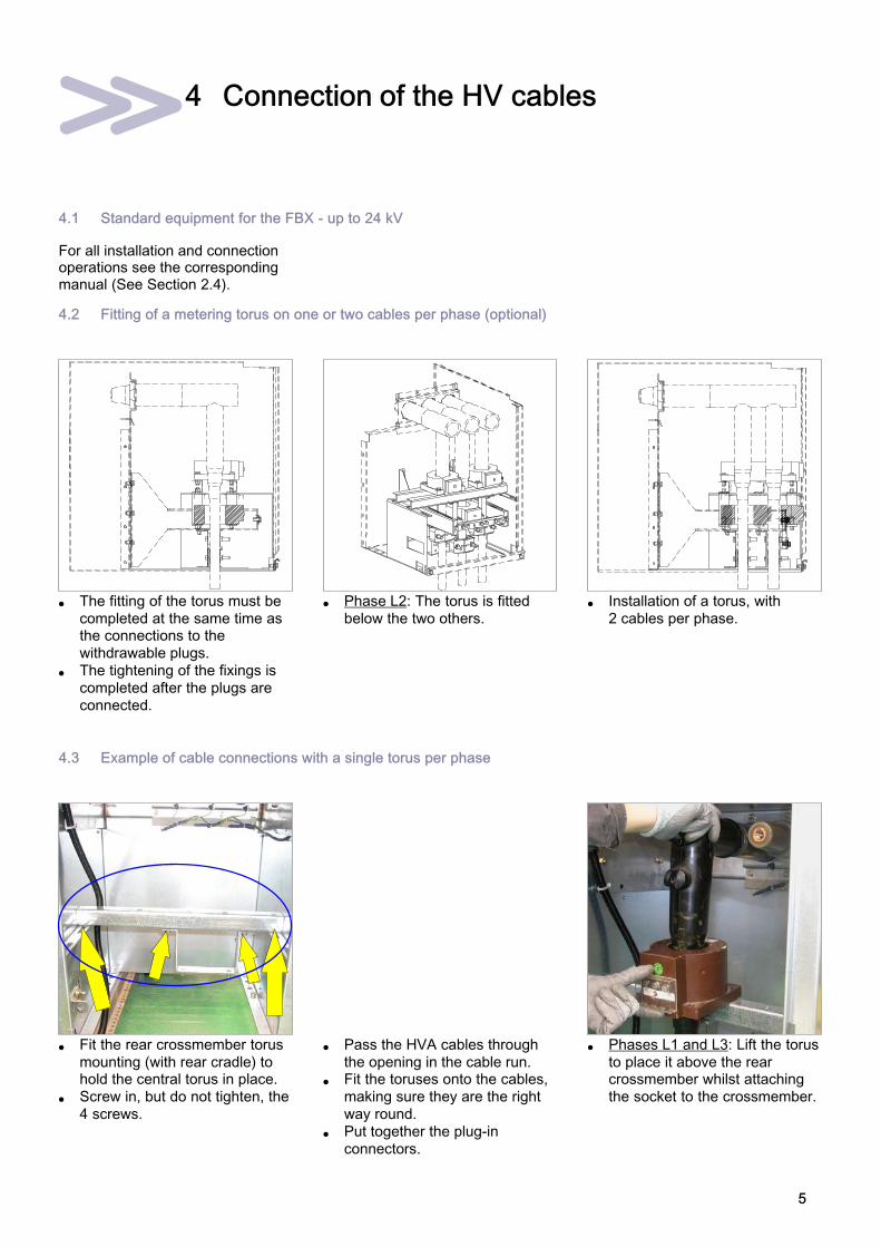
4.2 Fitting of a metering torus on one or two cables per phase (optional)
� The fitting of the torus must be
completed at the same time asthe connections to the
withdrawable plugs.
� The tightening of the fixings is
completed after the plugs are
connected.
� Phase L2: The torus is fitted
below the two others.
� Installation of a torus, with
2 cables per phase.
4.3 Example of cable connections with a single torus per phase
� Fit the rear crossmember torus
mounting (with rear cradle) tohold the central torus in place.
� Screw in, but do not tighten, the
4 screws.
� Pass the HVA cables through
the opening in the cable run.� Fit the toruses onto the cables,
making sure they are the right
way round.
� Put together the plug-in
connectors.
� Phases L1 and L3: Lift the torus
to place it above the rearcrossmember whilst attaching
the socket to the crossmember.

6
� Phase L2: Lift the torus to place
it in the rear cradle whilstattaching the socket to the
crossmember.
� Position the front crossmember.
� Attach the front crossmember
using 2 screws withouttightening them.
� Refit the front cradle for the
Phase L2 torus.
� Tighten the 2 screws on the
front cradle.
� Attach all toruses (4 screws per
unit).� Attach the earthing wire using
the front right hand side
mounting screw.
� The three toruses are shown in
place, without the phase L1 andL3 cables.
� Pass the LV wiring through, as
shown.
� Attach this wiring bundle in
three places.
� Remove the protective cover.
� Connect the secondary toruscircuits as per the identification
marks and diagrams.
� Refit the protective cover. � Tighten all fixing bolts.
Complete connectionby clamping the cables
(See the corresponding manual -Section 2.4).

7
5 Use of the CB function
5.1 Opening the earthing switch
� Check that the tag is fully
lowered.� Insert the appropriate lever (red
end) into the earthing switch
socket.
� Grasp the lever with both
hands.
� Lift the lever: the earthing switch
is now in the open position.� Remove the lever.
5.2 Closing the earthing switch
Before closing the earthing switch, ensure there is no voltage across the indicator units (see corresponding
manual - § 2.4).
� Hold the locking tab open to the
right.� Insert the appropriate lever (red
end) into the earthing switch
socket.
� Grasp the lever with both
hands.
� Pull the lever down: the earthing
switch is closed.� Remove the lever.

8
5.3 Closing the line isolating switch [earthing switch open - circuit breaker tripped]
� Lift the locking tab.
� Insert the lever (black end) intothe disconnector switch socket.
� Grasp the lever with both
hands.
� Lift the lever:
The line isolator is now closed.� Remove the lever.
5.4 Opening the line isolating switch [circuit breaker tripped]
� Lift the locking tab.
� Insert the lever (black end) intothe disconnector switch socket.
� Grasp the lever with both
hands.
� Pull the lever down:
The line isolator is now open.� Remove the lever.
5.5 Closing the circuit breaker [Line Isolator closed]
� Circuit breaker operating lever. � Circuit breaker open make sure
that the tag is fully lowered.� Introduce the lever into the
re-arming spring's switch hub.
� Turn the lever to the left to
re-arm the CB closing spring(rotate through approx. 350°).
Do not force the lever at the
end of the operating!
9
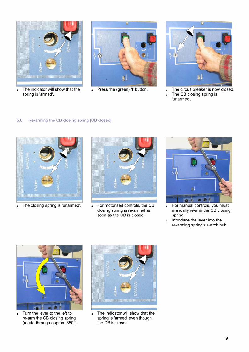
� The indicator will show that the
spring is 'armed'.
� Press the (green) 'I' button. � The circuit breaker is now closed.
� The CB closing spring is'unarmed'.
5.6 Re-arming the CB closing spring [CB closed]
� The closing spring is 'unarmed'. � For motorised controls, the CB
closing spring is re-armed assoon as the CB is closed.
� For manual controls, you must
manually re-arm the CB closingspring.
� Introduce the lever into the
re-arming spring's switch hub.
� Turn the lever to the left to
re-arm the CB closing spring(rotate through approx. 350°).
� The indicator will show that the
spring is 'armed' even thoughthe CB is closed.

10
5.7 Opening the circuit breaker [Line Isolator closed]
� Press the (red) 'O' button. � The circuit breaker is now open.

11
6 CB Function diagram
Key
Q01: circuit breaker
Q01-F11, Q01-F12: Trip Coils
Q01-F13: Undervoltage tripping coil
Q01-F14: Closure Coil
Q01-F31: striker pin
Q01-LS1 to LS3: spring position contacts
Q01-S1: Circuit breaker position contact
Q01-S52: Lever insertion locking contact
Q01-S53, Q01-S54: Motor interlock contacts
Q11: Disconnector
Q11-S1: Disconnector position contact
0 Q11-S51: Closing interlock contact
0 -H1: 'Pressure' indictor contact
0 -H301: 'Fault' indicator contact
0 C1: Connector
0 F1: Fuse
0 M: Motor
0 V01, V02: Bridge rectifiers
0 X1, X3: Test terminal box
0 X10, X12A: Connectors
0 X14, X15, X16: Connectors
6.1 "Metering - Protection - Signalling" section
Disconnector
position contacts
Positio
n C
onta
cts
for
the e
art
hin
g
sw
itch.
Arm
ed/U
narm
ed
positio
n c
onta
ct (o
ption)
Circuit breaker
position contacts
Protection
Metering (option)
Protection(Option -depending ontype of relay)
Conta
cts
for
sig
nalli
ng
pre
ssure
(option)
Conta
cts
for
sig
nalli
ng a
fault (
option)
The terminals of 'current' circuitsare highlighted and protected bya DANGER label.

12
'Control' section
Tripping Coil
Optional
Closing coil
2nd tripping coil
Underv
oltage trippin
g c
oil
(option)
Str
iker*
* (o
ption)
Optional
Motorization
Not simultaneously
Remove this
jumper if a
protection
relay is fitted
Anti-pumping systemMotorization board

13
7 WIC1 or DPX-1 protection relays (option)
7.1 Configuring the protection relays.
The relays are supplied pre-configured, with a default set
ting of their maximum levels.
To adjust the protectionrelays, see the manual sup
plied with the switchboard.
7.2 WIC1 & DPX-1 protection relays
� WIC1: Standard autonomous
protection relay (withoutearthing fault).
Optional: with earthing fault.
� DPX-1: Autonomous protection
relay with earthing faultdetection and indicator light:
- flashing green: OK,
- fixed green: problem with the
relay,
- fixed red: detection of fault
current.
Indicator
Orange
Violet
Brown
Blu
e
Yello
w
Red
Bla
ck
Gre
en
White
� WI1-SZ5: wiring connnectivity
diagram.
7.3 WI1-SZ5 fault indicator
� Indicator normal (no fault) � Indicator showing a fault (red) � Press the green button to delete
the fault.

14
8 Maintenance
8.1 Levels of maintenance
D e f i n i t i o n Levels
Operations recommended in the instructions manual "installation - operation - maintenance", carriedout by suitably qualified personnel having received training allowing them to intervene whilstrespecting the safety rules.
1
Complex operations, requiring specific expertise and the implementation of support equipment inaccordance with AREVA's procedures. These are carried out by AREVA or by a specialisedtechnician, trained by AREVA (see § 1.2) in the implementation of procedures, and who is equippedwith specific equipment.
2
All preventive and corrective maintenance, all renovation and reconstruction work is carried out byAREVA.
3
8.2 General Safety Instructions
Never separate the C150control mechanism from the
circuit breaker part.
Never remove the commandcontrol cover without having
cut off the LV auxiliaries.
Ensure that the springs havebeen released by carrying out
a complete O-C-O cycle.
8.3 Maintenance of the mechanical control mechanism
Under normal installation and service conditions, the CB630 circuitbreaker requires no maintenance:- throughout the 25 years of its service life,- as long as it has not reached themaximum number of operatingcycles.
By cycle we mean a closingthen an opening operation.
The internal electrical connections as well as the adjust
ments to the control mechanism
are carried out at the factory andcannot be modified.
P R E V E N T I V E M A I N T E N A N C E Frequency Levels
Recommended operations 3 years 1 2 3
Inspection of the tightening of the threaded fasteners and presence of stopelements
X - X X
Carry out a few opening and closing operations of the circuit breaker with themanual (and electrical) controls to ensure its correct operation.
X - X X
Monitor the general appearance of the mechanical components and connections X - X X
8.4 Corrective maintenance
C O R R E C T I V E M A I N T E N A N C E Levels
Replacements or modifications See chapter 1 2 3
Replacement of the motor (1) 8.7 - X X
Replacement of the tripping coil (2) 8.8 - X X
Replacement of an under/overvoltage tripping coil (3 and 4) 8.9 - X X
Replacement of a fuse striker (5) 8.10 - X X
Replacement of the undervoltage tripping coil (6) 8.11 - X X
Replacement of a diode bridge (7) 8.12 - X X
Replacing the motor electronic control card (8) 8.13 - X X
Replacement of a motor reset contact (9) 8.14 - X X

15
8.5 Removal of the protective cover for all maintenance operations
Maintenance operationsabsolutely must be carried
out with the circuit breaker openand the control mechanism deactivated.
Cut off the LV auxiliaries’power circuits,
Complete replacement of aC150 control mechanism can
only be carried out by AREVA(See § 1.1).
� Unscrew the 5 attachment
screws holding the front plates(Allen key - 4mm).
� Remove the plate � Unscrew the 4 cover fixing
screws (Allen key for hexagonalscrews size 4).
� Remove the complete cover
and twin front cover assembly.
� Unscrew the 4 cover mount
fixing screws (Allen key forhexagonal screws size 4).
� Pull off the cover mounts.
8.6 Location of LV components
7
� Location of LV elements
1
2 3 4 5
6
0 Key
- 1 Motor
- 2 Closing Coil
- 3 Tripping Coil on voltage release
- 4 Tripping Coil on voltagerelease/application
- 5 Striker
- 6 Electronic control board for voltage release coil
- 7 Diode bridge
- 8 Electronic motor board
- 9 Motor rearming contacts
8
9
16
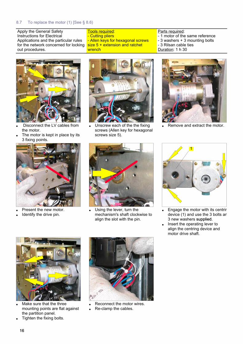
8.7 To replace the motor (1) [See § 8.6)
Apply the General SafetyInstructions for ElectricalApplications and the particular rulesfor the network concerned for lockingout procedures.
Tools required:- Cutting pliers- Allen keys for hexagonal screwssize 5 + extension and ratchetwrench
Parts required:- 1 motor of the same reference- 3 washers + 3 mounting bolts- 3 Rilsan cable tiesDuration: 1 h 30
� Disconnect the LV cables from
the motor.� The motor is kept in place by its
3 fixing points.
� Unscrew each of the the fixing
screws (Allen key for hexagonalscrews size 5).
� Remove and extract the motor.
� Present the new motor.
� Identify the drive pin.
� Using the lever, turn the
mechanism's shaft clockwise toalign the slot with the pin.
� Engage the motor with its centrin
device (1) and use the 3 bolts an3 new washers supplied.
� Insert the operating lever to
align the centring device and
motor drive shaft.
1
� Make sure that the three
mounting points are flat againstthe partition panel.
� Tighten the fixing bolts.
� Reconnect the motor wires.
� Re-clamp the cables.

17
8.8 Replacement of the tripping coil (2) [See Section 8.6]
Apply the General SafetyInstructions for ElectricalApplications and the particular rulesfor the network concerned for lockingout procedures.
Tools required:- Cutting pliers- Allen key for hexagonalscrew size 3- 2 x open-ended spanners - size 7
Parts required:- 1 coil with the same reference- 2 pre-treated bolts and 2 washers- 3 Rilsan cable tiesDuration: 1 h
� Hold the coil in place.
� Unscrew and remove the 2fixing bolts (Allen key of 3 mm).
� Cut the fixing collars on the
wiring.� Disconnect the connector from
the coil.
� Extract the coil from the front.
� Measure distance D1 on the
removed coil.
D1
� Measure the same distance D1
on the new coil.� Tighten the nuts.
� Positioning the new coil.
� Insert and tighten the 2 newmounting bolts supplied.
� Make sure that the distance
(D2) between the centre of thecoil and the drive tab is equal
to 4 mm.
D2
� Reconnect the LV connector.
� Fix the cables in place usingRislan cable ties.

18
8.9 Replacing an under/overvoltage tripping coil (3 or 4) [See Section 8.6]
Apply the General SafetyInstructions for ElectricalApplications and the particular rulesfor the network concerned for lockingout procedures.
Tools required:- Cutting pliers- Allen key for hexagonalscrew size 3- 2 x open-ended spanners - size 7
Parts required:- 1 coil with the same reference- 2 pre-treated bolts and 2 washers- 3 Rilsan cable tiesDuration: 1 h
Coil (4) may be eitheron voltagerelease/application.
For an undervoltage tripping coil,first remove the coil board (See Section 8.11).
� Cut the fixing collars on the
wiring.� Disconnect the connector from
the coil.
� Hold the coil in place.
� Unscrew and remove the 2fixing bolts (Allen key of 3 mm).
� Note which way round the coil
goes.� Remove this coil from the right
hand side.
� Measure distance D1 on the
removed coil.
D1
� Measure the same distance D1
on the new coil.� Tighten the nuts.
� Positioning the new coil.
� Insert and tighten the 2 newmounting bolts supplied.
� Make sure that the distance (D3)
between the centre of the coiland the trip tab is equal to 3 mm
D3
Top view
3
4
� Reconnect the LV connector.
� Fix the cables in place usingRislan cable ties.
19
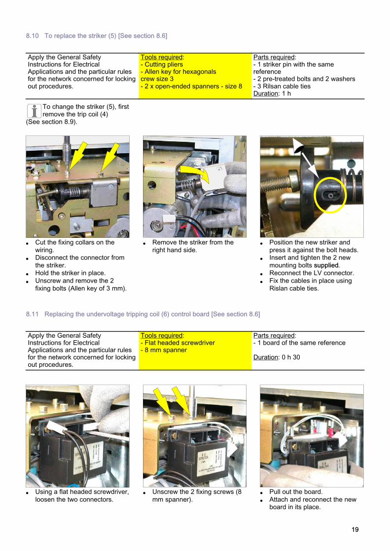
8.10 To replace the striker (5) [See section 8.6]
Apply the General SafetyInstructions for ElectricalApplications and the particular rulesfor the network concerned for lockingout procedures.
Tools required:- Cutting pliers- Allen key for hexagonalscrew size 3- 2 x open-ended spanners - size 8
Parts required:- 1 striker pin with the samereference- 2 pre-treated bolts and 2 washers- 3 Rilsan cable tiesDuration: 1 h
To change the striker (5), firstremove the trip coil (4)
(See section 8.9).
� Cut the fixing collars on the
wiring.� Disconnect the connector from
the striker.
� Hold the striker in place.
� Unscrew and remove the 2
fixing bolts (Allen key of 3 mm).
� Remove the striker from the
right hand side.
� Position the new striker and
press it against the bolt heads.� Insert and tighten the 2 new
mounting bolts supplied.
� Reconnect the LV connector.
� Fix the cables in place using
Rislan cable ties.
8.11 Replacing the undervoltage tripping coil (6) control board [See section 8.6]
Apply the General SafetyInstructions for ElectricalApplications and the particular rulesfor the network concerned for lockingout procedures.
Tools required:- Flat headed screwdriver- 8 mm spanner
Parts required:- 1 board of the same reference
Duration: 0 h 30
� Using a flat headed screwdriver,
loosen the two connectors.
� Unscrew the 2 fixing screws (8
mm spanner).
� Pull out the board.
� Attach and reconnect the newboard in its place.

20
8.12 Replacing the diode bridge (7) [See section 8.6]
Apply the General SafetyInstructions for ElectricalApplications and the particular rulesfor the network concerned for lockingout procedures.
Tools required:- Allen key for hexagonalscrew size 3- Flat headed screwdriver
Parts required:- 1 diode bridge of the samereference
Duration: 0 h 30
� Unscrew the central bolt holding
the bridge in place.� Replace the diode bridge
� Refit the new bridge in its place.
8.13 Replacing the motor control board (8) [See Section 8.6]
Apply the General SafetyInstructions for ElectricalApplications and the particular rulesfor the network concerned for lockingout procedures.
Tools required:- Allen key for hexagonalscrew size 3- Flat headed screwdriver
Parts required:- 1 board of the same reference
Duration: 1 h 00
� The motor control board is
lodged against the left handupright in the C150 control
compartment.
� Press the two pins on the front
to free the board.
� Lightly push the board aside
then pull forwards to free fromits rear connector.
� Pull out the board from the
bottom.
� Disconnect the board.
� Replace the board with one ofthe same reference.
� Repeat the operations detailed
above in reverse to refit the new
board.

21
8.14 Replacing a motor re-arming contact (9) [mechanical control tripped and un-armed]
� The motor re-arming contacts
are located in the bottom righthand corner of the C150,
behind the front panel.
� Loosen then remove the two
mounting bolts from the front.
� Remove the contact block.
� Replace the defective contact.
� Refit the block without
tightening the bolts.
Adjust the motor arming lock before the contacts.
� Loosen the 2 screws on the end
of the lock slightly.
� Turn this lock to align the arrow
horizontally in the window.
� Once this adjustment has been
made, tighten the 2 screws.
Adjusting the electrical arming contacts.
� Turn the mount to bring the
contact tabs into contact withthe lock.
� View of the inside of the
mechanism: The tabs arepressing against the lock probe.
� Tighten the 2 fixing screws.

22
9 Spare parts for the circuit breaker
9.1 Intervention levels
For an explanation of thelevels of maintenance, please
refer to § 8.1.
9.2 The spare part
Describes a part that is designed toreplace a corresponding one with aview to re-establishing the originalfunction.
The replacement of theseparts can only be carried out
by a person who is suitably qualified and trained for this operation.
Exceptional replacement DenominationLevels
1 2 3
Tripping coil (closing or tripping operations) - X X
Describes the spare parts or assemblieswhose foreseeable service life is at leastequal to that of the equipment.
Use: Spare parts or sub-assemblies keptin a safety stock.
Undervoltage coil - X X
Undervoltage coil control card - X X
Striker - X X
Diode bridge - X X
Motor - X X
Anti-pumping relay - X X
Operation counter - X X
Cirrcuit breaker auxiliary contact - X X
Spring position microswitch - X X
Microswitch (motor, undervoltage coil, locking) - X X
Ring - X X
Fitted C150 control - X X
9.3 Identification and storage of the parts
For all orders for spare parts,it is necessary to enclose the
equipment characteristics form.
The components should be storedaway from dust, humidity and thesun. In order to facilitate theirretrieval, they must be marked bythe AREVA reference number.
Certain components are fragile,they should preferably be stored intheir original factory packaging.

23
10 Notes
If you have any comments on the use of this document or on the use of the equipment and services thatare described in it, please send us your remarks, suggestions and wishes to:
AREVA Service Technique BP 84019 F-71040 Mâcon Cedex 9 - FRANCE
Fax: 33 (0)3 85 29 36 36

AM
TN
oT
17
0-0
2 0
0 (
06
/20
10
) �
- A
RE
VA
- 2
010.
AR
EV
A,
the A
RE
VA
logo a
nd a
ny a
ltern
ative v
ers
ion t
here
of
are
tra
dem
ark
s a
nd s
erv
ice m
ark
s o
f A
RE
VA
.T
he o
the
r nam
es m
entioned,
regis
tere
d o
r not, a
re t
he p
ropert
y o
f th
eir r
espective c
om
panie
s.
- 389191982 R
CS
PA
RIS
- C
reation :
AR
EV
A M
âcon -
Printe
d in F
rance.
AREVA T&D
Boulevard de la Résistance BP84019 F-71040 Mâcon Cedex 9 - FRANCE
Tel.: +33 (0)3 85 29 35 00 - Fax: +33 (0)3 85 29 36 36
Our policy is one of continuous development.Accordingly the design of our products maychange at any time. Whilst every effort ismade to produce up to date literature, thisbrochure should only be regarded as a guideand is intended for information purposes only.Its contents do not constitute an offer for saleor advise on the application of any productreferred to in it. We cannot be heldresponsible for any reliance on any decisionstaken on its contents without specific advice.

![Fireware v12.5.1 Release Notes - WatchGuard...l AnissuethattriggeredaJavaErrormessagewheneditingaVIFBOVPNtunnelhasbeenresolved. [FBX-16703} l SD-WANcannolongerbeenabledontheBOVPN-AllowPolicies.[FBX-16329]](https://img.pdfslide.net/doc/110x75/5ed28278145d7a22490e08bb/fireware-v1251-release-notes-watchguard-l-anissuethattriggeredajavaerrormessagewheneditingavifbovpntunnelhasbeenresolved.jpg)