Embed Size (px)
Citation preview
Biostar T-Series TForce 945P
User’s Manual i
FCC Information and Copyright This equipment has been tested and found to comply with the limits of a Class B digital device, pursuant to Part 15 of the FCC Rules. These limits are designed to provide reasonable protection against harmful interference in a residential installation. This equipment generates, uses and can radiate radio frequency energy and, if not installed and used in accordance with the instructions, may cause harmful interference to radio communications. There is no guarantee that interference will not occur in a particular installation.
The vendor makes no representations or warranties with respect to the contents here and specially disclaims any implied warranties of merchantability or fitness for any purpose. Further the vendor reserves the right to revise this publication and to make changes to the contents here without obligation to notify any party beforehand.
Duplication of this publication, in part or in whole, is not allowed without first obtaining the vendor’s approval in writing.
The content of this user’s manual is subject to be changed without notice and we will not be responsible for any mistakes found in this user’s manual. All the brand and product names are trademarks of their respective companies.
PACKAGE CHECKLIST FDD Cable x 1 HDD Cable x 1 User’s Manual x 1 Serial ATA Cable x 1 Serial ATA Power cable x1 Fully Setup Driver CD x 1 Rear I/O Panel for ATX Case x 1 USB 2.0 Cable x 1 (optional) SPDIF Cable x 1 (optional)
Biostar T-Series TForce 945P
User’s Manual ii
PACKAGE CHECKLIST..................................................................................... I
CHAPTER 1: INTRODUCTION......................................................1 1.1 MOTHERBOARD FEATURES...............................................................1 1.2 LAYOUT AND COMPONENTS...............................................................3
CHAPTER 2: HARDWARE INSTALLATION ...............................5 2.1 INSTALLING CENTRAL PRIOCESSING UNIT (CPU) .............................5 2.2 SYSTEM MEMORY .............................................................................7 2.3 PERIPHERALS ...................................................................................9
CHAPTER 3: OVERCLOCK QUICK GUIDE .............................20 3.1: T-POWER INTRODUCTION ...............................................................20 3.2: T-POWER BIOS FEATURE ..............................................................21 3.3 T-POWER WINDOWS FEATURE........................................................27
CHAPTER 4: USEFUL HELP ........................................................36 4.1 DRIVER INSTALLATION NOTE..........................................................36 4.2 AWARD BIOS BEEP CODE...............................................................37 4.3 EXTRA INFORMATION .....................................................................38 4.4 TROUBLESHOOTING........................................................................40
GERMAN ..........................................................................................41 FRENCH ...........................................................................................42 ITALIAN............................................................................................45 SPANISH ...........................................................................................47 PORTUGUESE .................................................................................49 POLAND ...........................................................................................51 RUSSIAN...........................................................................................53 ARABIC.............................................................................................55 JAPANESE........................................................................................57
Biostar T-Series TForce 945P
User’s Manual 1
CHAPTER 1: INTRODUCTION 1.1 MOTHERBOARD FEATURES
CPU Supports LGA 775. Supports Intel Pentium 4 processor and Celeron D. Supports Dual Core CPU
Supports Pentium D Supports Core2Duo (For Ver 2.0 only)
Front Side Bus at the following frequency ranges: 533MT/s (133MHzCore Clock) 800MT/s (200MHzCore Clock) 1066MT/s (266MHzCore Clock)
Supports Hyper-Threading Technology (HT). Supports Execute Disable Bit Technology (XD). Supports Enhanced Intel SpeedStep® Technology (EIST). Supports Intel Extended Memory 64 Technology (Intel EM64T).
Chipset North Bridge: Intel 945P South Bridge: Intel ICH7.
Operating Systems Supports Windows 2000 and Windows XP.
Dimensions ATX Form Factor: 20.5cm (L) x 30.5cm (W)
System Memory Supports Dual Channel DDR2. Supports DDR2 400/533/667. Maximum memory capacity is 4GB, supporting 4 DIMM sockets.
Super I/O Chip: ITE IT8712F. Environment Control initiatives,
H/W Monitor Fan Speed Controller ITE's "Smart Guardian" function
Serial ATA II Controller integrated in ICH7, supports SATA 2.0 specification,
with data transfer rates up to 3Gb/s. AC’97 Audio Sound Codec
Chip: REALTEK ALC655, supports 6 channels audio output. IDE
1 on-board connectors support 2 IDE disk drives. Supports PIO mode 0-4, Block Mode and Ultra DMA 33/66/100
bus master mode.
Biostar T-Series TForce 945P
User’s Manual 2
Gigabit Ethernet LAN PHY: RTL 8110S-32 / 8110SC. Supports 10Mb/s, 100Mb/s and
1GB/s auto-negotiation. Internal On-board Slots and Connectors
1 floppy connector. 1 PCI-Express x16 slot. 2 PCI-Express x1 slots. 1 CD-ROM audio-in connector. 1 SPDIF-Out connector. 1 Ultra DMA 100/66/33 IDE connectors. 3 PCI slots. 4 SATA II ports. 2 USB headers support 4 USB 2.0 ports at front panel. 1 front panel header supports front panel facilities
Back Panel I/O Connectors and Ports 1 Serial Port. 1 Printer Port. 1 RJ-45 LAN jack. 1 PS/2 Mouse Port. 1 PS/2 Keyboard Port. 4 USB 2.0 Ports. 3 audio ports support 6 channels audio-out facilities.
Biostar T-Series TForce 945P
User’s Manual 3
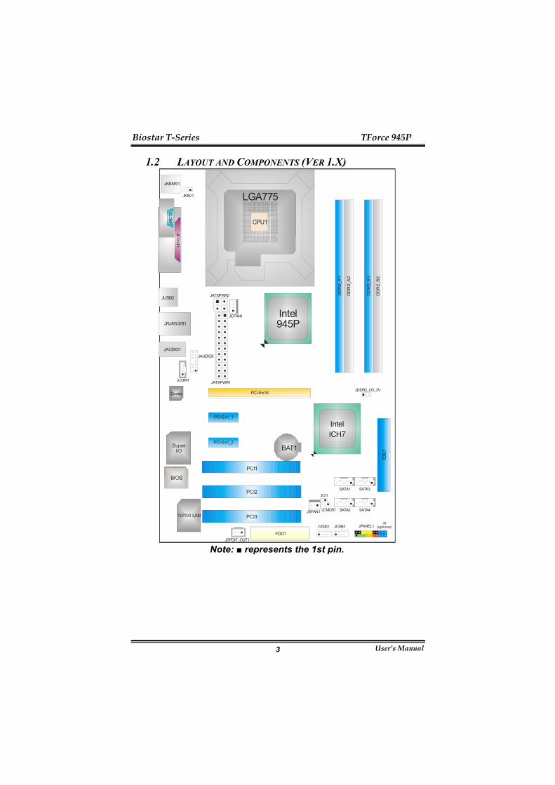
1.2 LAYOUT AND COMPONENTS (VER 1.X)
DD
R2_
A1
DD
R2_
A2
DD
R2_
B1
DD
R2_
B2
FDD1
IDE
1
PCI-Ex1_1
PCI-Ex1_2
PCI-Ex16
PCI1
PCI2
PCI3
JPANEL1JUSB4JUSB3
JATXPWR1
JCFAN1
JATXPWR2
JAUDIO1JAUDIO6
JDDR2_OV_3V
SuperI/O
JCI1
JCMOS1
SATA1
SATA2
SATA3
SATA4
Codec
JCDIN1
JSPDIF_OUT1
JSFAN110/100 LAN
BAT1
BIOS
JKBMS1
JUSB2
JRJ45USB1
IntelICH7
LGA775
CPU1
CO
M1
JCO
M1
Intel945P
JKBV1
JPR
NT1
IR(optional )
Note: ■ represents the 1st pin.

Biostar T-Series TForce 945P
User’s Manual 4
1.3 LAYOUT AND COMPONENTS (VER 2.X)
DD
R2_
A1
DD
R2_
A2
DD
R2_
B1
DD
R2_
B2
FDD1
IDE
1
PCI-Ex1_1
PCI-Ex1_2
PCI-Ex16
PCI1
PCI2
PCI3
JPANEL1JUSB4JUSB3
JATXPWR1
JCFAN1
JATXPWR2
JAUDIO1JAUDIO6
JDDRII_2.2V
SuperI/O
JCI1
JCMOS1
SATA1
SATA2
SATA3
SATA4
Codec
JCDIN1
JSPDIF_OUT1
JSFAN110/100 LAN
BAT1
BIOS
JKBMS1
JUSB2
JRJ45USB1
IntelICH7
LGA775
CPU1
CO
M1
JCO
M1
Intel945P
JKBV1
JPR
NT1
RSTSW1
PWRSW1
Note: ■ represents the 1st pin.

Biostar T-Series TForce 945P
User’s Manual 5
CHAPTER 2: HARDWARE INSTALLATION 2.1 INSTALLING CENTRAL PROCESSING UNIT (CPU) A. Central Processing Unit (CPU)
Special Notice: Remove Pin Cap before installation, and make good preservation for future use. When the CPU is removed, cover the Pin Cap on the empty socket to ensure pin legs won’t be damaged.
pin cap
Step 1: Pull the socket locking lever out from the socket and then raise the lever up to a 90-degree angle.
Step 2: Look for the triangular cut edge on socket, and the golden dot on CPU should point towards this triangular cut edge. The CPU will fit only in the correct orientation. Step 2-1:
Step 2-2:

Biostar T-Series TForce 945P
User’s Manual 6
Step 3: Hold the CPU down firmly, and then lower the lever to locked position to complete the installation.
Step 4: Put the CPU Fan and heatsink assembly on the CPU and buckle it on the retention frame. Connect the CPU FAN power cable into the JCFAN1. This completes the installation.
B. About FAN Headers CPU FAN Power Header: JCFAN1 System Fan Power Headers: JSFAN1
JCFAN1: Pin Assignment 1 Ground 2 +12V 3 FAN RPM rate
sense 4 Smart Fan
Control JSFAN1:
Pin Assignment 1 Ground 2 +12V
JCFAN14
1
1 3
JSFAN113
3 FAN RPM rate sense
Note: JCFAN1 reserves system cooling fan with Smart Fan Control utilities. It supports 4 pin head connector. When connecting with wires onto connectors, please note that the red wire is the positive and should be connected to pin#2, and the black wire is Ground and should be connected to GND.

Biostar T-Series TForce 945P
User’s Manual 7
2.2 SYSTEM MEMORY
DD
R2_
A1D
DR
2_A2
DD
R2_
B1D
DR
2_B2
A. DDR 2 Modules 1. Unlock a DIMM slot by pressing the retaining clips outward.
Align a DIMM on the slot such that the notch on the DIMM matches the break on the slot.
2. Insert the DIMM vertically and firmly into the slot until the
retaining chip snaps back in place and the DIMM is properly seated.
Notes: To remove the DDR modules, push the ejector tabs at both sides of the slot outward at the same time, and pull the modules out vertically.
B. Memory Capacity DIMM Socket
Location DDR Module Total Memory Size
DDR2_A1 256MB/512MB/1GB *1DDR2_A2 256MB/512MB/1GB *1DDR2_B1 256MB/512MB/1GB *1DDR2_B2 256MB/512MB/1GB *1
Max is 4GB.
Biostar T-Series TForce 945P
User’s Manual 8
C. Dual Channel Memory installation To trigger the Duo Channel function of the motherboard, the memory module must meet the following requirements: Install Memory module of the same capacity in both channel 1 (DDR2_A1&DDR2_A2) and Channel 2 (DDR2_B1&DDR2_B2) The DRAM bus width of the memory module must be the same (x8 or x16) Notes: Using different memory chips on dual channel memory modules will result in unstable system performance.
Biostar T-Series TForce 945P
User’s Manual 9
2.3 PERIPHERALS A. Card and I/O Slots:
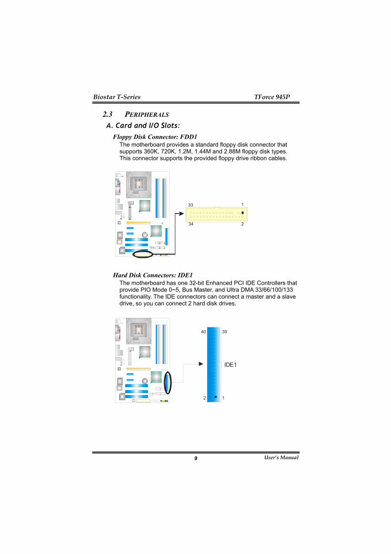
Floppy Disk Connector: FDD1 The motherboard provides a standard floppy disk connector that supports 360K, 720K, 1.2M, 1.44M and 2.88M floppy disk types. This connector supports the provided floppy drive ribbon cables.
1
2
33
34
Hard Disk Connectors: IDE1 The motherboard has one 32-bit Enhanced PCI IDE Controllers that provide PIO Mode 0~5, Bus Master, and Ultra DMA 33/66/100/133 functionality. The IDE connectors can connect a master and a slave drive, so you can connect 2 hard disk drives.
12
3940
IDE1
Biostar T-Series TForce 945P
User’s Manual 10
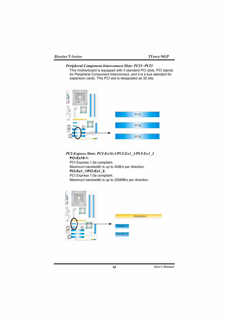
Peripheral Component Interconnect Slots: PCI1~PCI3 This motherboard is equipped with 3 standard PCI slots. PCI stands for Peripheral Component Interconnect, and it is a bus standard for expansion cards. This PCI slot is designated as 32 bits.
PCI1
PCI2
PCI3
PCI-Express Slots: PCI-Ex16-1/PCI-Ex1_1/PCI-Ex1_2 PCI-Ex16-1: PCI Express 1.0a compliant. Maximum bandwidth is up to 4GB/s per direction. PCI-Ex1_1/PCI-Ex1_2: PCI Express 1.0a compliant. Maximum bandwidth is up to 250MB/s per direction.
PCI-Ex16-1
PCI-Ex1_1
PCI-Ex1_2
Biostar T-Series TForce 945P
User’s Manual 11
B. Connectors and Headers: How to setup Jumpers
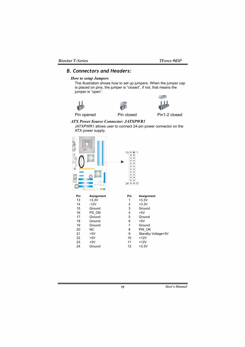
The illustration shows how to set up jumpers. When the jumper cap is placed on pins, the jumper is “closed”, if not, that means the jumper is “open”.
Pin opened Pin closed Pin1-2 closed
ATX Power Source Connector: JATXPWR1 JATXPWR1 allows user to connect 24-pin power connector on the ATX power supply.
13
24
1
12
Pin Assignment Pin Assignment 13 +3.3V 1 +3.3V 14 -12V 2 +3.3V 15 Ground 3 Ground 16 PS_ON 4 +5V 17 Ground 5 Ground 18 Ground 6 +5V 19 Ground 7 Ground 20 NC 8 PW_OK 21 +5V 9 Standby Voltage+5V 22 +5V 10 +12V 23 +5V 11 +12V 24 Ground 12 +3.3V
Biostar T-Series TForce 945P
User’s Manual 12
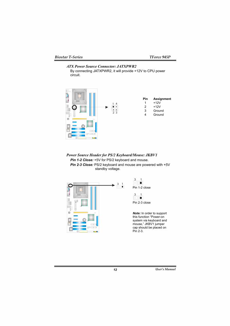
ATX Power Source Connector: JATXPWR2 By connecting JATXPWR2, it will provide +12V to CPU power circuit.
Pin
Assignment
1 +12V 2 +12V 3 Ground
2
1 4
3
4 Ground
Power Source Header for PS/2 Keyboard/Mouse: JKBV1 Pin 1-2 Close: +5V for PS/2 keyboard and mouse. Pin 2-3 Close: PS/2 keyboard and mouse are powered with +5V
standby voltage.
13
13
Pin 1-2 close
13
Pin 2-3 close Note: In order to support this function “Power-on system via keyboard and mouse,” JKBV1 jumper cap should be placed on Pin 2-3.

Biostar T-Series TForce 945P
User’s Manual 13
Front Panel Audio-out Header: JAUDIO6 This connector will allow user to connect with the front audio output headers on the PC case. It will disable the output on back panel audio connectors.
12
14 13
Pin Assignment Pin Assignment
14 Left line in/ Rear speaker Left
13 Left line in/ Rear speaker Left
12 Right line in/ Rear speaker Right
11 Right line in/ Rear speaker Right
10 Left line out/ Speaker out Left
9 Left line out/ Speaker out Left
8 Key 7 Reserved
6 Right line out/ Speaker out Right
5 Right line out/ Speaker out Right
4 Audio power 3 Mic power/Bass 2 Ground 1 Mic in/center
Biostar T-Series TForce 945P
User’s Manual 14
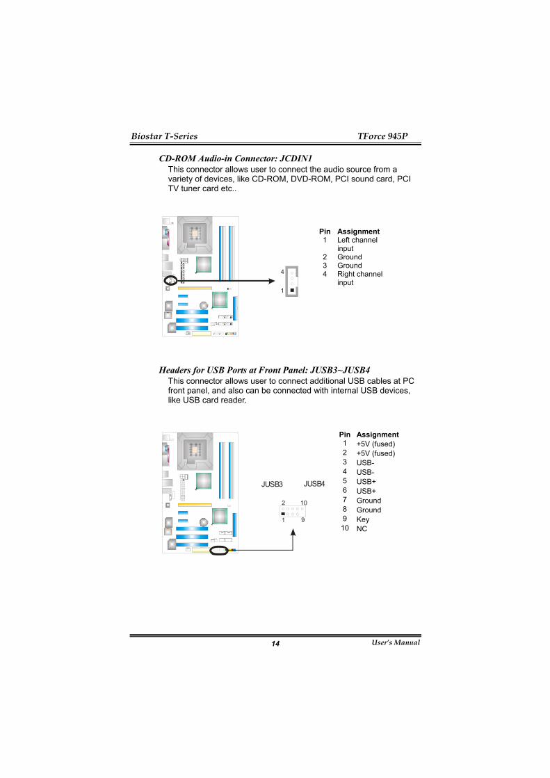
CD-ROM Audio-in Connector: JCDIN1 This connector allows user to connect the audio source from a variety of devices, like CD-ROM, DVD-ROM, PCI sound card, PCI TV tuner card etc..
Pin
Assignment
1 Left channel input
2 Ground 3 Ground
4
1
4 Right channel input
Headers for USB Ports at Front Panel: JUSB3~JUSB4 This connector allows user to connect additional USB cables at PC front panel, and also can be connected with internal USB devices, like USB card reader.
Pin
Assignment
1 +5V (fused) 2 +5V (fused) 3 USB- 4 USB- 5 USB+ 6 USB+ 7 Ground 8 Ground 9 Key
2 10
91
JUSB3 JUSB4
10 NC

Biostar T-Series TForce 945P
User’s Manual 15
JPANEL1: Header for Front Panel Facilities This 16-pin connector includes Power-on, Reset, HDD LED, Power LED, Sleep button, speaker Connection. It allows user to connect the PC case’s front panel switch functions.
1 1122
SLPPWR_LED
On/OffIR(Optional)
RSTHLED
SPK
+ +
+
12-
-
Pin Assignment Function Pin Assignment Function1 +5V 12 Sleep control 2 N/A 13 Ground
Sleep button
3 N/A 14 N/A N/A 4 Speaker
Speaker nector
15 Power LED (+) 5 HDD LED (+) 16 Power LED (+) 6 HDD LED (-)
Hard drive LED 17 Power LED (-)
Power LED
7 Ground 18 Power button 8 Reset control
Reset button 19 Ground
Power-on button
9 N/A 20 Key 10 +5V 21 Ground 11 IRTX
IrDA Connector(Optional) 22 IRRX
IrDA Connector(Optional)

Biostar T-Series TForce 945P
User’s Manual 16
JPANEL1: Header for Front Panel Facilities (Ver 2.0 only) This 16-pin connector includes Power-on, Reset, HDD LED, Power LED, Sleep button, speaker Connection. It allows user to connect the PC case’s front panel switch functions.
1 816
SLPPWR_LED
On/Off
RSTHLED
SPK
+ +
+
9-
-
Pin Assignment Function Pin Assignment Function1 +5V 9 Sleep control 2 N/A 10 Ground
Sleep button
3 N/A 11 N/A N/A 4 Speaker
Speaker nector
12 Power LED (+) 5 HDD LED (+) 13 Power LED (+) 6 HDD LED (-)
Hard drive LED 14 Power LED (-)
Power LED
7 Ground 15 Power button 8 Reset control
Reset button 16 Ground
Power-on button
Digital Audio-out Connector: JSPDIF_OUT1
This connector allows users to connect the PCI bracket SPDIF output header.
Pin
Assignment
1 +5V 2 SPDIF OUT
3 1
3 Ground
Biostar T-Series TForce 945P
User’s Manual 17
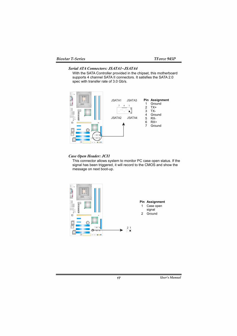
Serial ATA Connectors: JSATA1~JSATA4 With the SATA Controller provided in the chipset, this motherboard supports 4 channel SATA II connectors. It satisfies the SATA 2.0 spec with transfer rate of 3.0 Gb/s.
Pin
Assignment
1 Ground 2 TX+ 3 TX- 4 Ground 5 RX- 6 RX+
JSATA4JSATA2
JSATA1 JSATA3
147
7 Ground
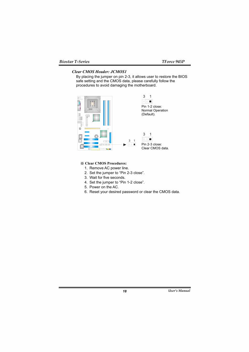
Case Open Header: JCI1 This connector allows system to monitor PC case open status. If the signal has been triggered, it will record to the CMOS and show the message on next boot-up.
Pin
Assignment
1 Case open signal
12
2 Ground
Biostar T-Series TForce 945P
User’s Manual 18
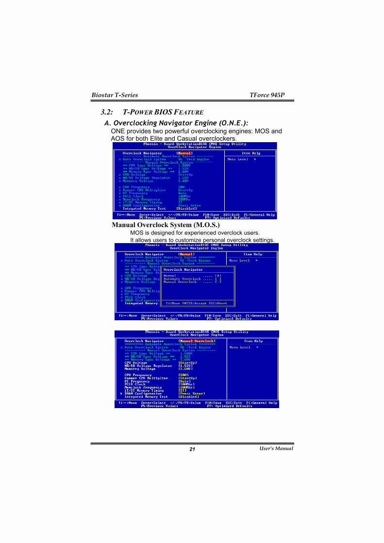
Clear CMOS Header: JCMOS1 By placing the jumper on pin 2-3, it allows user to restore the BIOS safe setting and the CMOS data, please carefully follow the procedures to avoid damaging the motherboard.
13
Pin 1-2 close: Normal Operation (Default).
13
13
Pin 2-3 close: Clear CMOS data.
Clear CMOS Procedures:※ 1. Remove AC power line. 2. Set the jumper to “Pin 2-3 close”. 3. Wait for five seconds. 4. Set the jumper to “Pin 1-2 close”. 5. Power on the AC. 6. Reset your desired password or clear the CMOS data.

Biostar T-Series TForce 945P
User’s Manual 19
Header for Memory Voltage Customize: JDDR = 2.3V (JDDRII_2.2V in Ver 2.0)
When processing Memory Voltage Overclocking, please place the jumper to pin1-2 closed. The Default setting is Pin 2-3 Closed.
1 3
Pin 1-2 close: Enable memory voltage customize.
1 3
1 3
Pin 2-3 close: (Default).
Note: 1. When “JDDR =2.3V” jumper cap is placed on Pin 1-2,
memory voltage will be fixed at 2.3V automatically, and can’t be adjusted under COMS setup.
2. When “JDDR =2.3V” jumper cap is placed on Pin 2-3, memory voltage can be manually adjusted under CMOS setup.
Before setting memory voltage overclocking, please make sure that your DDR supports up to 2.3V. (Consult your DDR memory module supplier)
On-board buttons (Ver 2.0 only) There are 2 on-board buttons
PWRSW1
RSTSW1
PWRSW1: This is an on-board Power Switch button RSTSW1`: This is an on-board Reset button

Biostar T-Series TForce 945P
User’s Manual 20
CHAPTER 3: OVERCLOCK QUICK GUIDE 3.1: T-POWER INTRODUCTION
Biostar T-Power is a whole new utility that is designed for overclock users. Based on many precise tests, Biostar Engineering Team (BET) has developed this ultimate overclock engine to raise system performance. No matter whether under BIOS or Windows interface, T-Power is able to present the best system state according to users’ overclock setting. T-Power BIOS Features:
Overclocking Navigator Engine (O.N.E.) CMOS Reloading Program (C.R.P.) Memory Integration Test (M.I.T., under Overclock Navigator
Engine) Integrated Flash Program (I.F.P.) Smart Fan Function (under PC Health Status) Self Recovery System (S.R.S)
T-Power Windows Feature: Hardware Monitor Overclock Engine Smart Fan Function Life Update
Biostar T-Series TForce 945P
User’s Manual 21
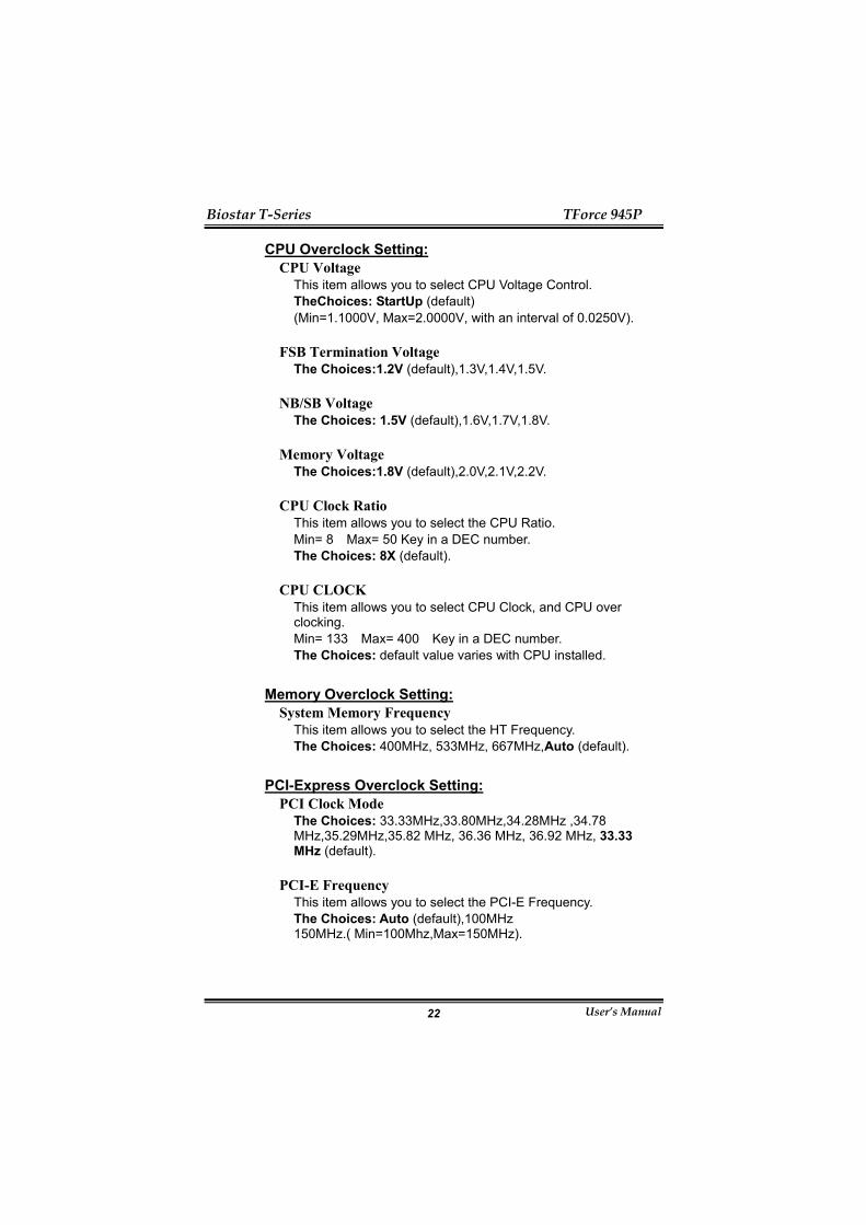
3.2: T-POWER BIOS FEATURE A. Overclocking Navigator Engine (O.N.E.):
ONE provides two powerful overclocking engines: MOS and AOS for both Elite and Casual overclockers.
Manual Overclock System (M.O.S.)
MOS is designed for experienced overclock users. It allows users to customize personal overclock settings.
Biostar T-Series TForce 945P
User’s Manual 22
CPU Overclock Setting: CPU Voltage
This item allows you to select CPU Voltage Control. TheChoices: StartUp (default) (Min=1.1000V, Max=2.0000V, with an interval of 0.0250V).
FSB Termination Voltage The Choices:1.2V (default),1.3V,1.4V,1.5V.
NB/SB Voltage The Choices: 1.5V (default),1.6V,1.7V,1.8V.
Memory Voltage The Choices:1.8V (default),2.0V,2.1V,2.2V.
CPU Clock Ratio This item allows you to select the CPU Ratio. Min= 8 Max= 50 Key in a DEC number. The Choices: 8X (default).
CPU CLOCK This item allows you to select CPU Clock, and CPU over clocking. Min= 133 Max= 400 Key in a DEC number. The Choices: default value varies with CPU installed.
Memory Overclock Setting: System Memory Frequency
This item allows you to select the HT Frequency. The Choices: 400MHz, 533MHz, 667MHz,Auto (default).
PCI-Express Overclock Setting: PCI Clock Mode
The Choices: 33.33MHz,33.80MHz,34.28MHz ,34.78 MHz,35.29MHz,35.82 MHz, 36.36 MHz, 36.92 MHz, 33.33 MHz (default).
PCI-E Frequency This item allows you to select the PCI-E Frequency. The Choices: Auto (default),100MHz 150MHz.( Min=100Mhz,Max=150MHz).
Biostar T-Series TForce 945P
User’s Manual 23
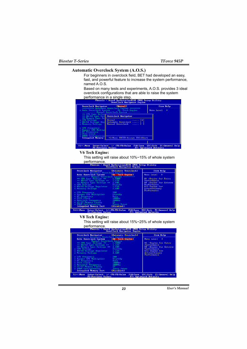
Automatic Overclock System (A.O.S.) For beginners in overclock field, BET had developed an easy, fast, and powerful feature to increase the system performance, named A.O.S. Based on many tests and experiments, A.O.S. provides 3 ideal overclock configurations that are able to raise the system performance in a single step.
V6 Tech Engine:
This setting will raise about 10%~15% of whole system performance.
V8 Tech Engine:
This setting will raise about 15%~25% of whole system performance.

Biostar T-Series TForce 945P
User’s Manual 24
V12 Tech Engine: This setting will raise about 25%~30% of whole system performance.
B. CMOS Reloading Program (C.R.P.): It allows users to save different CMOS settings into BIOS-ROM. Users are able to reload any saved CMOS setting for customizing system configurations. Moreover, users are able to save an ideal overclock setting during overclock operation. There are 50 sets of record addresses in total, and users are able to name the CMOS data according to personal preference.

Biostar T-Series TForce 945P
User’s Manual 25
C. Memory Integration Test (M.I.T.): This function is under “Overclocking Navigator Engine” item. MIT allows users to test memory compatibilities, and no extra devices or software are needed.
Step 1: The default setting under this item is “Disabled”; the condition parameter should be changed to “Enable” to proceed this test.
↓
Step 2:
Save and Exit from CMOS setup and reboot the system to activate this test. Run this test for 5 minutes (minimum) to ensure the memory stability.
Step 3: When the process is done, change the setting back from “Enable” to “Disable” to complete the test.
Biostar T-Series TForce 945P
User’s Manual 26
D. Self Recovery System (S.R.S.): This function can’t be seen under T-Power BIOS setup; and is always on whenever the system starts up. However, it can prevent system hang-up due to inappropriate overclock actions. When the system hangs up, S.R.S. will automatically log in the default BIOS setting, and all overclock settings will be re-configured.
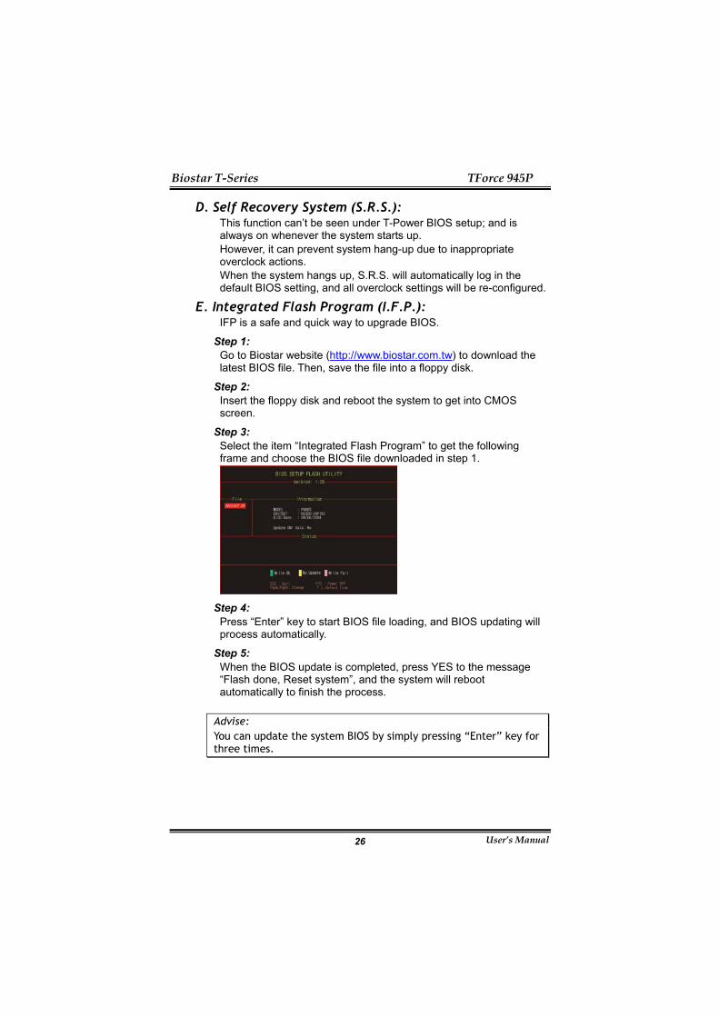
E. Integrated Flash Program (I.F.P.): IFP is a safe and quick way to upgrade BIOS.
Step 1: Go to Biostar website (http://www.biostar.com.tw) to download the latest BIOS file. Then, save the file into a floppy disk.
Step 2: Insert the floppy disk and reboot the system to get into CMOS screen.
Step 3: Select the item “Integrated Flash Program” to get the following frame and choose the BIOS file downloaded in step 1.
Step 4:
Press “Enter” key to start BIOS file loading, and BIOS updating will process automatically.
Step 5: When the BIOS update is completed, press YES to the message “Flash done, Reset system”, and the system will reboot automatically to finish the process.
Advise: You can update the system BIOS by simply pressing “Enter” key for three times.

Biostar T-Series TForce 945P
User’s Manual 27
3.3 T-POWER WINDOWS FEATURE A.Hardware Monitor:
T-Power Hardware monitor allows users to monitor system voltage, temperature and fan speed accordingly. Additionally, a rescue action will be taken by the program automatically while the system faces an abnormal condition. The program will trigger an alarm or shut down the system when unpredictable errors occur. All the monitoring items are illustrated by a waveform diagram.
Hardware Monitor Toolbar
i. Start-up Setting Click on this item to run Hardware Monitor Program when the Windows starts-up.
ii. Dialogue-Box Setting Click on this item to pop-up warning dialogue-box when PC system is abnormal.
iii. Exit Click on this item to exit Hardware Monitor Program.
iv. Hide Click on this item to hide this program in system tray. When hiding the program, there will be a check icon in the system tray.
Biostar T-Series TForce 945P
User’s Manual 28
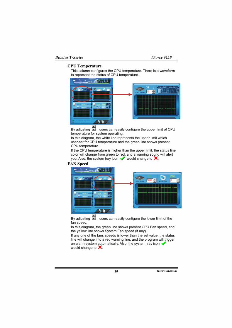
CPU Temperature This column configures the CPU temperature. There is a waveform to represent the status of CPU temperature.
By adjusting , users can easily configure the upper limit of CPU temperature for system operating. In this diagram, the white line represents the upper limit which user-set for CPU temperature and the green line shows present CPU temperature. If the CPU temperature is higher than the upper limit, the status line color will change from green to red, and a warning sound will alert you. Also, the system tray icon would change to .
FAN Speed
By adjusting , users can easily configure the lower limit of the fan speed. In this diagram, the green line shows present CPU Fan speed, and the yellow line shows System Fan speed (if any). If any one of the fans speeds is lower than the set value, the status line will change into a red warning line, and the program will trigger an alarm system automatically. Also, the system tray icon would change to .

Biostar T-Series TForce 945P
User’s Manual 29
CPU/Battery Voltage
i. VCore This item displays the CPU voltage, represented by a light blue line.
Users can set the upper and lower limit by adjusting to monitor the CPU operating voltage. If CPU voltage is higher or lower than the set value, the status line will change into a red warning line, and a warning sound will alert you. Also, the system tray icon will change to .
ii. VBAT This item displays the CMOS battery voltage, represented by a light green line.
Users can set the upper and lower limit by adjusting to monitor the status of battery voltage. If battery voltage is higher or lower than the set value, the status line will change to a red warning line, and a warning sound will alert you. Also, the system tray icon will change to .
Reference data This column represents the status of power supply voltage and cannot be adjusted, it is only for present status reference.

Biostar T-Series TForce 945P
User’s Manual 30
B. Overclocking Configurations
This diagram is designed for T-series Overclocking utility. Friendly interface and solid overclock features are the major concept of this utility. Graphic 1 will appear when activating this utility.
Graphic 1
Graphic 2
A. Clicking on “Biostar” will lead you to the Biostar Homepage.
B. This column shows the CPU speed information.
C. Click on this button and the utility will pop-up 4 sub-screens (Please refers to Graphic 3).
D. Click on this button to minimize this program to taskbar.
E. This column shows present CPU speed and overclocking percentage.
F. Clicking on this button will make the program start up as soon as the Windows starts up.
G. Click on this button to exit this overclock utility.
H. Click on this button to reset all the overclock features to default setting.
By adjusting the overclocking features in 4 sub-screens, users can tune the system performance to an optimal level.
Graphic 3
Biostar T-Series TForce 945P
User’s Manual 31
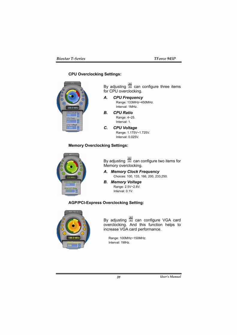
CPU Overclocking Settings:
By adjusting can configure three items for CPU overclocking. A. CPU Frequency
Range: 133MHz~450MHz. Interval: 1MHz.
B. CPU Ratio Range: 4~25. Interval: 1.
C. CPU Voltage Range: 1.175V~1.725V. Interval: 0.025V.
Memory Overclocking Settings:
By adjusting can configure two items for Memory overclocking. A. Memory Clock Frequency
Choices: 100, 133, 166, 200, 233,250.
B. Memory Voltage Range: 2.5V~2.8V. Interval: 0.1V.
AGP/PCI-Express Overclocking Setting:
By adjusting can configure VGA card overclocking. And this function helps to increase VGA card performance.
Range: 100MHz~150MHz. Interval: 1MHz.

Biostar T-Series TForce 945P
User’s Manual 32
PCI Overclocking Setting:
This diagram shows present PCI working status and helps to monitor PCI peripherals working status. This item cannot be adjusted.
Biostar T-Series TForce 945P
User’s Manual 33
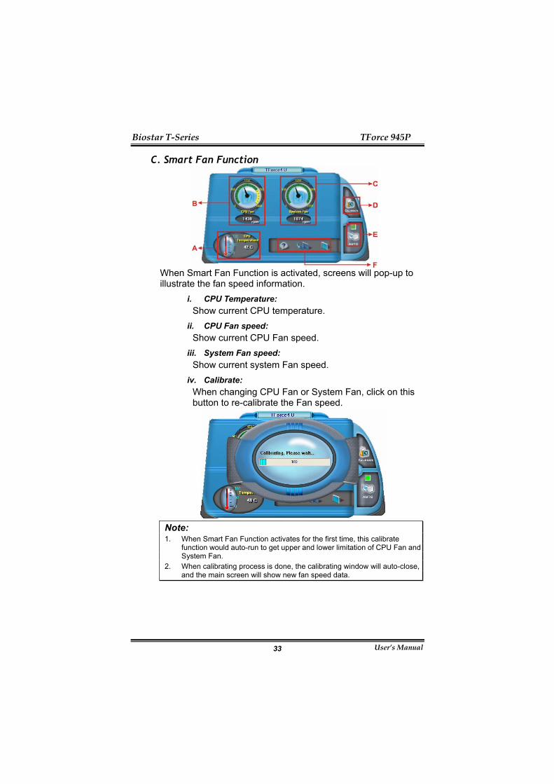
C. Smart Fan Function
When Smart Fan Function is activated, screens will pop-up to illustrate the fan speed information.
i. CPU Temperature: Show current CPU temperature.
ii. CPU Fan speed: Show current CPU Fan speed.
iii. System Fan speed: Show current system Fan speed.
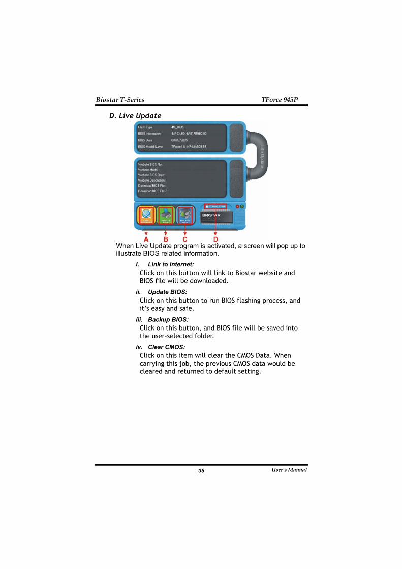
iv. Calibrate: When changing CPU Fan or System Fan, click on this button to re-calibrate the Fan speed.
Note: 1. When Smart Fan Function activates for the first time, this calibrate
function would auto-run to get upper and lower limitation of CPU Fan and System Fan.
2. When calibrating process is done, the calibrating window will auto-close, and the main screen will show new fan speed data.

Biostar T-Series TForce 945P
User’s Manual 34
v. Auto: If the green indicator is lit up, the Smart Fan Function is “On” (Default Setting). Click on this button again to close Smart Fan Function, and a screen as below would pop-up. There will be pulling-meter besides the CPU Fan and System Fan, the CPU Fan and the System Fan speed can be adjusted by adjusting the Cursor Up or Down.
vi. Program Tool Bar:
About: Click on this button to get program-related information.
Minimize: Click on this button to minimize the program to system tray
Exit: Click on this button to exit this program.
Biostar T-Series TForce 945P
User’s Manual 35
D. Live Update
When Live Update program is activated, a screen will pop up to illustrate BIOS related information.
i. Link to Internet: Click on this button will link to Biostar website and BIOS file will be downloaded.
ii. Update BIOS: Click on this button to run BIOS flashing process, and it’s easy and safe.
iii. Backup BIOS: Click on this button, and BIOS file will be saved into the user-selected folder.
iv. Clear CMOS: Click on this item will clear the CMOS Data. When carrying this job, the previous CMOS data would be cleared and returned to default setting.
Biostar T-Series TForce 945P
User’s Manual 36
CHAPTER 4: USEFUL HELP 4.1 DRIVER INSTALLATION NOTE
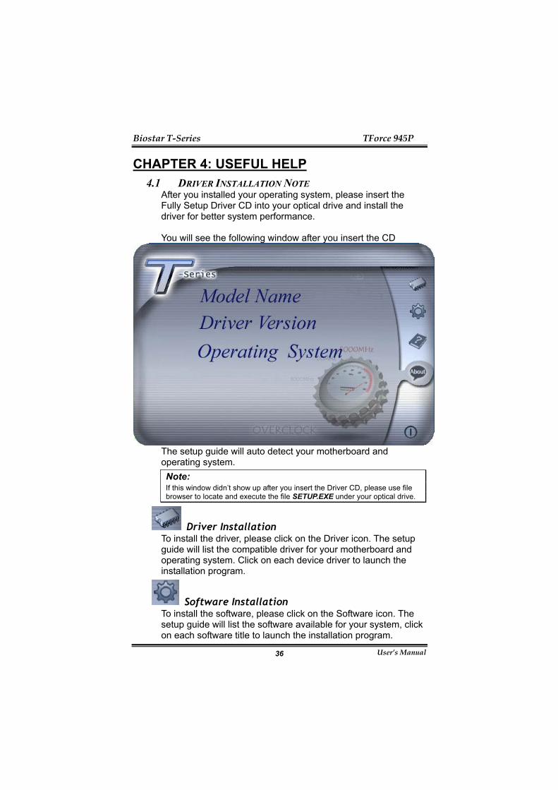
After you installed your operating system, please insert the Fully Setup Driver CD into your optical drive and install the driver for better system performance. You will see the following window after you insert the CD
The setup guide will auto detect your motherboard and operating system. Note: If this window didn’t show up after you insert the Driver CD, please use file browser to locate and execute the file SETUP.EXE under your optical drive.
Driver Installation To install the driver, please click on the Driver icon. The setup guide will list the compatible driver for your motherboard and operating system. Click on each device driver to launch the installation program.
Software Installation To install the software, please click on the Software icon. The setup guide will list the software available for your system, click on each software title to launch the installation program.

Biostar T-Series TForce 945P
User’s Manual 37
Manual Aside from the paperback manual, we also provide manual in the Driver CD. Click on the Manual icon to browse for available manual. Note: You will need Acrobat Reader to open the manual file. Please download the latest version of Acrobat Reader software from http://www.adobe.com/products/acrobat/readstep2.html
4.2 AWARD BIOS BEEP CODE Beep Sound Meaning
One long beep followed by two short beeps
Video card not found or video card memory bad
High-low siren sound CPU overheated System will shut down automatically
One Short beep when system boots-up No error found during POST
Long beeps every other second No DRAM detected or installed
Biostar T-Series TForce 945P
User’s Manual 38
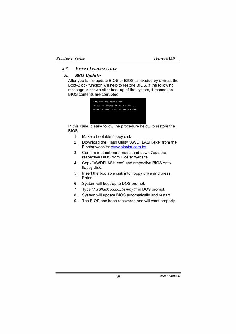
4.3 EXTRA INFORMATION A. BIOS Update
After you fail to update BIOS or BIOS is invaded by a virus, the Boot-Block function will help to restore BIOS. If the following message is shown after boot-up of the system, it means the BIOS contents are corrupted.
In this case, please follow the procedure below to restore the BIOS:
1. Make a bootable floppy disk. 2. Download the Flash Utility “AWDFLASH.exe” from the
Biostar website: www.biostar.com.tw 3. Confirm motherboard model and downl7oad the
respective BIOS from Biostar website. 4. Copy “AWDFLASH.exe” and respective BIOS onto
floppy disk. 5. Insert the bootable disk into floppy drive and press
Enter. 6. System will boot-up to DOS prompt. 7. Type “Awdflash xxxx.bf/sn/py/r” in DOS prompt. 8. System will update BIOS automatically and restart. 9. The BIOS has been recovered and will work properly.
Biostar T-Series TForce 945P
User’s Manual 39
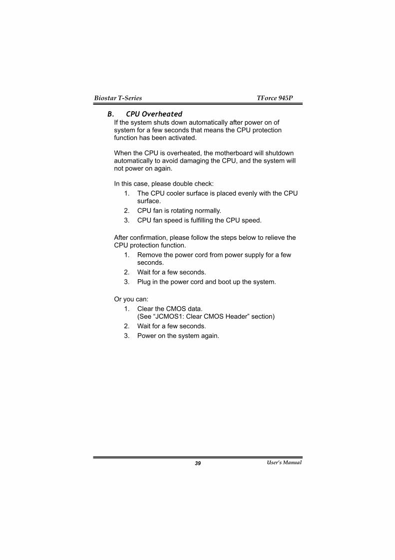
B. CPU Overheated If the system shuts down automatically after power on of system for a few seconds that means the CPU protection function has been activated. When the CPU is overheated, the motherboard will shutdown automatically to avoid damaging the CPU, and the system will not power on again. In this case, please double check:
1. The CPU cooler surface is placed evenly with the CPU surface.
2. CPU fan is rotating normally. 3. CPU fan speed is fulfilling the CPU speed.
After confirmation, please follow the steps below to relieve the CPU protection function.
1. Remove the power cord from power supply for a few seconds.
2. Wait for a few seconds. 3. Plug in the power cord and boot up the system.
Or you can: 1. Clear the CMOS data.
(See “JCMOS1: Clear CMOS Header” section) 2. Wait for a few seconds. 3. Power on the system again.
Biostar T-Series TForce 945P
User’s Manual 40
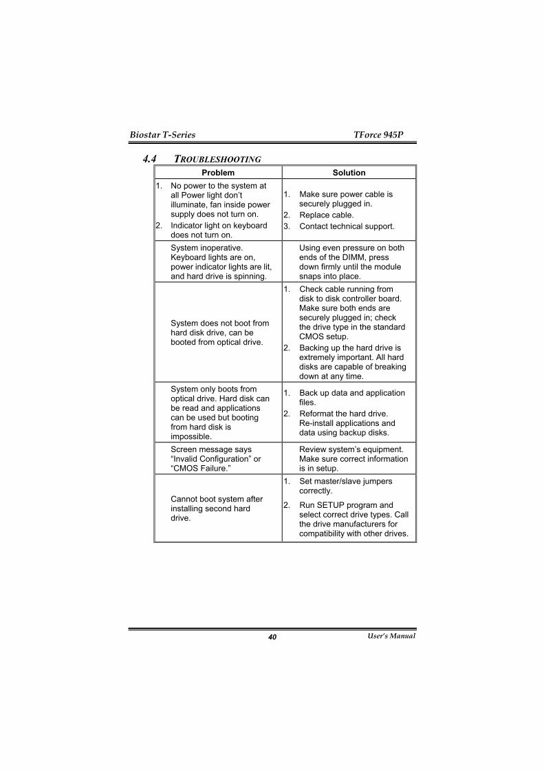
4.4 TROUBLESHOOTING Problem Solution
1. No power to the system at all Power light don’t illuminate, fan inside power supply does not turn on.
2. Indicator light on keyboard does not turn on.
1. Make sure power cable is securely plugged in.
2. Replace cable. 3. Contact technical support.
System inoperative. Keyboard lights are on, power indicator lights are lit, and hard drive is spinning.
Using even pressure on both ends of the DIMM, press down firmly until the module snaps into place.
System does not boot from hard disk drive, can be booted from optical drive.
1. Check cable running from disk to disk controller board. Make sure both ends are securely plugged in; check the drive type in the standard CMOS setup.
2. Backing up the hard drive is extremely important. All hard disks are capable of breaking down at any time.
System only boots from optical drive. Hard disk can be read and applications can be used but booting from hard disk is impossible.
1. Back up data and application files.
2. Reformat the hard drive. Re-install applications and data using backup disks.
Screen message says “Invalid Configuration” or “CMOS Failure.”
Review system’s equipment. Make sure correct information is in setup.
Cannot boot system after installing second hard drive.
1. Set master/slave jumpers correctly.
2. Run SETUP program and select correct drive types. Call the drive manufacturers for compatibility with other drives.

Biostar T-Series TForce 945P
User’s Manual 41
GERMAN CPU
Unterstützt LGA 775. Unterstützt Intel Pentium 4-Prozessoren und Celeron D. Unterstützt Dual-Core-CPU
Unterstützt Pentium D Unterstützt Core2Duo (nur für Ver 2.0)
Unterstützt die folgenden Front Side Bus-Frequenzen: 533MT/s (133MHz Kerntakt) 800MT/s (200MHz Kerntakt) 1066MT/s (266MHz Kerntakt)
Unterstützt die Hyper-Threading Technology (HT) Unterstützt die Execute Disable Bit Technology (XD). Unterstützt die Enhanced Intel SpeedStep® Technology (EIST). Unterstützt die Intel Extended Memory 64 Technology (Intel
EM64T). Chipsatz
North Bridge: Intel 945P. South Bridge: Intel ICH7
Betriebssystemunterstützung Unterstützt Windows 2000 und Windows XP.
Abmessungen ATX-Formfaktor: 20.5cm (L) x 30.5cm (B)
Systemspeicher Unterstützt Dual-Kanal DDR2. Unterstützt DDR2 533/ 667. Unterstützt die Speichergröße von maximal 4GB mit 4
DIMM-Steckplätze Serial ATA II
Intel ICH7 unterstützt die Serial ATA 2.0-Spezifikation, datentransferrate von bis zu 3GB/s.
IDE 1 integrierte Anschlüsse für 2 Geräte.
Unterstützt PIO-Modus 0-4, Blockmodus und Ultra DMA 33/66/100 Bus-Mastermodus.
Super E/A Chip: ITE IT8712F. Systemumgebungskontrolle:
Hardwareüberwachung Lüfterdrehzahl-Controller "Smart Guardian"-Funktion von ITE
AC’97 Sound-Codec Chip: ALC655, unterstützt 6 Kanäle.

Biostar T-Series TForce 945P
User’s Manual 42
10/100/1000 LAN Realtek 8110S-32 / 8110SC, Unterstützt 10Mb/s, 100Mb/s und
1GB/s Auto-Negotiation. Interne integrierte Steckplätze und Anschlüsse
1 Diskettenlaufwerkanschluss. 1 PCI-Express x16-Steckplatz. 2 PCI-Express x1-Steckplätze. 1 CD-ROM-Audioeingang 1 S/PDIF-Ausgangsanschluss 1 Ultra DMA 100/66/33 IDE-Anschlüsse 3 PCI-Steckplätze 4 Serial ATA –Anschlüsse 2 USB-Anschlussleisten unterstützen 6 USB 2.0-Ports an der
Frontseite 1 Frontseitenanschlussleiste zur Unterstützung von
Bedienelementen an der Frontseite. 1 Frontseitenanschlussleiste zur Unterstützung von Bedienelementen an der Frontseite.Rücktafel-E/A-Anschlüsse
1 serieller Anschluss 1 drucker Anschluss 1 RJ-45 LAN-Anschluss 1 PS/2-Mausanschluss 1 PS/2-Tastaturanschluss 4 USB 2.0-Anschlüsse 3 Audioanschlüsse für 6-Kanal-Audioausgabefunktionen.

Biostar T-Series TForce 945P
User’s Manual 43
FRENCH Processeur
Prise en charge de LGA 775. Prise en charge des processeurs Intel Pentium 4 et Celeron D. Prise en charge CPU Dual Core.
Prise en charge de Pentium D Prise en charge de Core2Duo (Seulement pour Ver 2.0)
Bus front-side aux fréquences suivantes : 533MT/s (Horloge cœur 133MHz) 800MT/s (Horloge coeur 200MHz) 1066MT/s (Horloge coeur 266MHz)
Prise en charge de la technologie Hyper-Threading. (HT) Prise en charge de la technologie Execute Disable Bit (XD). Prise en charge de la technologie Enhanced Intel SpeedStep®
(EIST). Prise en charge de la technologie Intel Extended Memory 64 (Intel
EM64T). Chipset
North Bridge: Intel 945P. South Bridge: Intel ICH7.
Systèmes d'exploitation pris en charge Prise en charge de Windows 2000 et Windows XP.
Dimensions Facteur de forme ATX: 20.5cm (Long) x 30.5cm (Larg)
Mémoire système Prise en charge des DDR2 double canal. Prise en charge de DDR2 533/667. Espace mémoire maximum de 4GB, prenant en charge 4 barrettes
DIMM. Codec audio AC’97
Chip: ALC655, prise en charge 6 canaux. E/S disque
Chip : ITE IT8712F. Initiatives Contrôle d'environnement,
Moniteur matériel Contrôleur de vitesse de ventilateur Fonction "Smart Guardian" d'ITE
ATA II Série Intel ICH7 prise en charge des spécifications ATA 2.0 Série, débit
de transfert des données jusqu'à 3 Go/s.

Biostar T-Series TForce 945P
User’s Manual 44
IDE 1 connecteurs sur carte permettant la prise en charge de 2
périphériques. Prise en charge PIO mode 0-4, Block Mode et mode bus maître
Ultra DMA 33/66/100. 10/100/1000 LAN
RTL 8110S-32 / 8110SC, Prise en charge de l'auto-négociation 10Mo/s, 100Mo/s et 1Go/s.
Emplacements et connecteurs sur carte internes 1 connecteur pour le lecteur de disquette 1 emplacement PCI-Express x16. 2 emplacements PCI-Express x1. 1 connecteur d'entrée CD-ROM audio-in 1 connecteur de sortie SPDIF-Out 1 connecteurs IDE Ultra DMA 100/66/33 3 emplacements PCI 4 ports série ATA 2 connecteurs USB prennent en charge 6 ports USB 2.0 sur le
panneau avant 1 connecteur sur le panneau avant prend en charge les fonctions
du panneau avant Connecteurs E/S panneau arrière
1 port série 1 port imprimeur 1 prise LAN RJ-45 1 port souris PS/2 1 port clavier PS/2 1 ports USB 2.0 3 ports audio prenant en charge les équipements de sortie audio 6
voies.

Biostar T-Series TForce 945P
User’s Manual 45
ITALIAN CPU
Supporto LGA 775. Supporto processore Intel Pentium 4 ed Celeron D. CPU Dual Core.
Supporto Pentium D Supporto Core2Duo (solo per Ver 2.0)
FSB (Front Side Bus) alle seguenti portate di frequenza: 533MT/s (133MHz Core Clock) 800MT/s (200MHz Core Clock) 1066MT/s (266MHz Core Clock)
Supporto tecnologia HT (Hyper Threading). Supporto tecnologia XD (Execute Disable Bit). Supporto tecnologia EIST (Enhanced Intel SpeedStep®
Technology). Supporto tecnologia Intel EM64T (Extended Memory 64
Technology). Chipset
North Bridge: Intel 945P. South Bridge: Intel ICH7.
ortati Supporto di Windows 2000 e Windows XP.
Dimensioni Fattore di forma ATX: 20.5 cm (L) x 30.5 cm (P)
Memoria di sistema Supporto di moduli DDR2 a doppio canale. Supporto di DDR2 533/667. Lo spazio massimo di memoria è 4GB e supporta 4 prese DIMM.
Serial ATA II Intel ICH7 supporto specifiche Serial ATA 2.0, velocità di
trasferimento dei dati fino 3GB/s. Super I/O
Chip: ITE IT8712F. Funzioni di controllo dell’ambiente:
Monitoraggio hardware Controller velocità ventolina Funzione "Smart Guardian" di ITE
IDE 1 connettori integrati supportano 2 dispositivi. Modalità: PIO 0-4, bus master Block e Ultra DMA 33/66/100.
Audio Codec AC’97 Chip: ALC655, supporto di 6 canali.

Biostar T-Series TForce 945P
User’s Manual 46
10/100/1000 LAN Realtek RTL 8110S-32 / 8110SC, Supporto negoziazione
automatica a 10Mb/s, 100Mb/s e 1GB/s. Connettori e alloggiamenti interni integrato
1 connettore floppy 1 alloggiamento PCI-Express x16. 2 alloggiamenti PCI-Express x1. 1 connettore SPDIF-Out. 1 connettore ingresso audio CD-ROM 1 connettori Ultra DMA 100/66/33 IDE 3 alloggiamenti PCI 4 porte Serial ATA. 2 connettori USB supportano 6 porte USB 2.0 sul pannello
frontale. 1 connettore sul pannello frontale supporta i dispositivi del
pannello frontale. Connettori I/O del pannello posteriore
1 porta seriale 1 porta stampatore 1 connettore LAN RJ-45 1 porta mouse PS/2 1 porta tastiera PS/2 4 porte USB 2.0 3 porte audio supportano 6 canali di servizio rendimento audio.

Biostar T-Series TForce 945P
User’s Manual 47
SPANISH Procesador
Compatible con LGA 775. Compatible con el procesador Intel Pentium 4 y Celeron D. Admite procesador de núcleo dual.
Compatible con Pentium D Compatible con Core2Duo (solamente para Ver 2.0)
FSB (Front Side Bus) en los siguientes intervalos de frecuencia: 533 MT/s (reloj principal a 133 MHz) 800 MT/s (reloj principal a 200 MHz) 1066 MT/s (reloj principal a 266 MHz)
Compatible con la tecnología Hyper-Threading (HT). Compatible con la tecnología de bit para deshabilitar la ejecución
(XD, Execute Disable). Compatible con la tecnología SpeedStep® de Intel mejorada
(EIST). Compatible con la tecnología 64 de memoria extendida (Intel
EM64T, Extended Memory 64 Technology)
Conjunto de chips North Bridge: Intel 945P. South Bridge: Intel ICH7.
Sistemas operativos compatibles Compatible con Windows 2000 y Windows XP.
Dimensiones Formato ATX: 20.5 cm (LA) x 30.5 cm (AN)
Memoria del sistema Compatible con admite DDR2 de canal dual. Compatible con admite DDR2 533/667. Espacio máximo de memoria de 4GB, que admite 4 zócalos
DIMM. Serial ATA II
Intel ICH7 compatible con la especificación Serial ATA 2.0, tasa de transferencia de datos de hasta 3 GB/s.
IDE Dos conectores integrados que admiten 4 dispositivos. Admite el modo PIO 0-4, el modo de bloque y el modo de bus
maestro Ultra DMA 33/66/100. Súper E/S
Procesador: ITE IT8712F. Iniciativas de control medioambiental:
Supervisor H/W Controlador de la velocidad del ventilador Función "Guardián inteligente" de ITE

Biostar T-Series TForce 945P
User’s Manual 48
Códec de audio AC’97 Procesador: ALC655, admite 6 canales.
10/100/1000 LAN Realtek RTL 8110S-32 / 8110SC, Admite negociación automática
a 10 Mb/s, 100 Mb/s y 1 GB/s. Conectores y ranuras integrados e internos
1 conector de disco extraíble. 1 ranura 16X PCI-Express. 2 ranuras PCI-Express 1X. 1 conector de entrada de audio en CD-ROM 1 conector de salida SPDIF 1 conectores Ultra DMA 100/66/33 IDE 3 ranuras PCI 4 puertos Serial ATA. 2 cabezales USB soportan 6 puertos USB 2.0 en el panel frontal. 1 cabezal del panel frontal soporta funciones de panel frontal.
Conectores de E/S del panel posterior 1 puerto serie 1 puerto impresora 1 conector de red LAN RJ-45 1 puerto para ratón PS/2 1 puerto para teclado PS/2 4 puertos USB 2.0 3 puertos de audio que admiten 6 conexiones de salida de audio
de 8 canales.
Biostar T-Series TForce 945P
User’s Manual 49
PORTUGUESE CPU
Suporta o socket LGA 775. Suporta um processador Intel Pentium 4 e Celeron D. Suporta uma CPU dual core.
Suporta um Pentium D Suporta um Core2Duo (apenas para os modelos Ver 2.0)
FSB (Front Side Bus) com as seguintes frequências: 533 MT/s (133 MHz) 800 MT/s (200 MHz) 1066 MT/s (266 MHz)
Suporta a tecnologia Hyper-Threading (HT). Suporta a tecnologia Execute Disable Bit Technology (XD). Suporta a tecnologia Enhanced Intel SpeedStep®Technology
(EIST). Suporta a tecnologia Intel Extended Memory 64 Technology (Intel
EM64T). Chipset
Ponte Norte: Intel 945P. Ponte Sul: Intel ICH7.
Sistemas operativos suportados: Suporta o Windows 2000 e o Windows XP.
Dimensões Factor de forma ATX: 20.5 cm (C) x 30.5 cm (L)
Memória do sistema Suporta DDR2 de duplo canal. Suporta módulos DDR2 533/ 667. Capacidade máxima da memória: 4GB, suportando 4 sockets
DIMM. Serial ATA II
Intel ICH7 suporta a especificação Serial ATA 2.0, velocidade de transferência de dados até3 GB/s.
IDE 1 conectores na placa para 2 dispositivos. Suporta o modo PIO 0-4, o modo Block e o modo bus master Ultra
DMA 33/66/100. Especificação Super I/O
Chip: ITE IT8712F. Iniciativas para controlo do ambiente,
Monitorização do hardware Controlador da velocidade da ventoinha Função "Smart Guardian" da ITE

Biostar T-Series TForce 945P
User’s Manual 50
Codec de som AC'97 Chip: ALC655, suporta 6 canais.
10/100/1000 LAN Realtek RTL 8110S-32 / 8110SC, Suporta a especificação de auto
negociação de 10Mb/s, 100Mb/s e 1GB/s. Conectores e ranhuras internos na placa
Existência de um conector para unidade de disquetes. 1 ranhura PCI Express x16. 2 ranhuras PCI Express x1. 1 conector S/PDIF-Out 1 conector CD-ROM para entrada de áudio 1 conectores Ultra DMA 100/66/33 IDE 3 ranhuras PCI 4 portas Serial ATA. 2 conectores USB suportam 6 portas USB 2.0 no painel frontal. Existência de um conector no painel frontal para uma maior
facilidade de ligação. Conectores I/O do painel traseiro
porta série 1 porta impressora 1 tomada LAN RJ-45 1 porta para rato PS/2 1 porta para teclado PS/2 4 portas USB 2.0 3 portas de áudio para saída de 6 canais de áudio.

Biostar T-Series TForce 945P
User’s Manual 51
POLAND PROCESOR
Obsługa LGA 775. Obsługa procesorów Intel Pentium 4 i Celeron D. Procesor dwurdzeniowy (Dual Core).
Obsługa Pentium D Obsługa Core2Duo (wyłącznie dla Ver 2.0)
Magistrala Front Side Bus o następujących zakresach częstotliwości: 533MT/s (zegar jądra 133MHz) 800MT/s (zegar jądra 200MHz) 1066MT/s (zegar jądra 266MHz)
Obsługa technologii HT (Hyper-Threading) Obsługa technologii XD (Execute Disable Bit Technology). Obsługa technologii EIST (Enhanced Intel SpeedStep®
Technology). Obsługa technologii Intel Extended Memory 64 Technology (Intel
EM64T). Chipset
Mostek północny: Intel 945P. Mostek południowy: Intel ICH7.
Obsługiwane systemy operacyjne Obsługa Windows 2000 oraz Windows XP.
Wymiary Obudowa ATX: 20.5cm (D) x 30.5cm (S)
Pamięć systemowa Obsługa DDR2 dual channel. Obsługa DDR2 533/667 Maksymalna wielkość pamięci wynosi 4GB z obsługą 4 gniazd
DIMM. IDE
1 wbudowane złącza z możliwością obsługi 2 urządzeń. Obsługa trybu PIO 0-4, Block Mode (tryb Blok) oraz tryb magistrali
głównej Ultra DMA 33/66/100. Serial ATA II
Intel ICH7. obsługa specyfikacji Serial ATA 2.0, transfer danych do 3GB/s.
Super I/O Chip: ITE IT8712F Inicjatywy kontroli środowiska,
Monitor H/W Kontroler prędkości wentylatora Funkcja ITE "Smart Guardian"

Biostar T-Series TForce 945P
User’s Manual 52
Kodek dźwięku AC’97 Chip: ALC655, obsługa 6 kanałów.
10/100/1000 LAN Realtek RTL 8110S-32 / 8110SC S, Obsługa szybkości 10Mb/s,
100Mb/s oraz 1GB/s z automatyczną negocjacją. Wewnętrzne, wbudowane gniazda oraz złącza
Jedno napędu złącze dyskietek elastycznych. 1 gniazdo PCI-Express x16. 2 gniazda PCI-Express x1. 1 złącze wyjścia SPDIF 1 wejścia audio CD-ROM 1 złącza Ultra DMA 133/100/66/33 IDE 3 gniazda PCI 4 porty Serial ATA. 2 złącza główkowe USB obsługujące 6 portów USB 2.0 na panelu
przednim. Jedno złącze główkowe panela przedniego, obsługujące
urządzenia panela przedniego. Złącza I/O na panelu tylnym
port drukarki 1 port szeregowy 1 gniazdo LAN RJ-45 1 port myszy PS/2 1 port klawiatury PS/2 4 porty USB 2.0 3 portów audio obsługujące 6 kanałów wyjścia audio.

Biostar T-Series TForce 945P
User’s Manual 53
RUSSIAN Процессор
Поддерживает LGA 775. Поддерживает процессоры Intel Pentium 4 и Celeron D. Поддержка двуядерных процессоров
Поддерживает Pentium D Поддерживает Core2Duo (только для Ver 2.0)
Поддерживаются следующие частоты системной шины: 533 МГц (133 МГц базовая частота) 800 МГц (200 МГц базовая частота) 1066 МГц (266 МГц базовая частота)
Поддерживает технологию Hyper-Threading (HT). Поддерживает технологию бита запрета исполнения (XD). Поддерживает улучшенную технологию Intel SpeedStep®
(EIST). Поддерживает технологию Intel Extended Memory 64(Intel
EM64T). Набор микросхем
Северный мост: Intel 945P. Южный мост: Intel ICH7. Поддерживаемые операционные системы
Поддерживает Windows 2000 и Windows XP. Размеры
Форм-фактор ATX: 20.5 x 30.5cm (Д x Ш) Системная память
Поддержка двухканальной памяти DDR2. Поддерживает DDR2 4533/ 667. Максимальный объем памяти 4 Гб в 4 гнездах DIMM. Звуковой кодек AC’97
Контроллер::ALC655, поддерживает 6-канальный звук. Супер ввод-вывод
Контроллер: ITE IT8712F. Функции управления режимом эксплуатации,
Монитор состояния оборудования Контроллер скорости вентиляторов Функция «Smart Guardian» компании ITE
Serial ATA II Intel ICH7 поддерживает спецификацию Serial ATA 2.0, скорость передачи данных до или 3 Гб/с.
IDE 1 встроенных разъема поддерживают подключение четырех жестких дисков IDE.
Поддержка режимов PIO 0-4, Block Mode и Ultra DMA 33/66/100.

Biostar T-Series TForce 945P
User’s Manual 54
10/100/1000 LAN Realtek 8110S-32 / 8110SC, Поддерживает автоматическое определение скорости 10 Мбит/с, 100 Мбит/с и 1 Гбит/с.
Встроенные разъемы ввода-вывода 1 разъем для дисковода гибких дисков. 1 слот PCI Express x16. 2 слота PCI Express x1 1 входной разъем звукового сигнала с привода для компакт-дисков
1 разъем SPDIF-Out 1 разъем Ultra DMA 133/100/66/33 IDE 3 слота PCI 4 порта Serial ATA 2 разъема USB поддерживают 6 портов USB 2.0 на передней панели
1 разъем для интерфейсов передней панели поддерживает порты на передней панели.
Разъемы ввода-вывода на задней панели последовательный порт 1 порт принтер 1 гнездо RJ-45 ЛВС 1 порт мыши PS/2 1 порт клавиатуры PS/2 4 порта USB 2.0 3 звуковых портов поддерживают подключение 6 каналов аудиовыхода.
Biostar T-Series TForce 945P
User’s Manual 55
ARABIC )CPU(وحدة المعالجة المرآزية
.LGA 775تدعم Intel Pentium 4. & Celeron Dتدعم معالج .دعم وحدات المعالجة المرآزية ذات اللب المزدوج Pentium D تدعم - )قط ف2.0في ( Core2Duo تدعم - :ناقل الجانب األمامي عند نطاقات التردد التالية - 533 MT/S) 133ميجا هرتز في الساعة الرئيسية ( - 800 MT/S) 200ميجا هرتز في الساعة الرئيسية ( - 1066 MT/S) 266ميجا هرتز في الساعة الرئيسية ( ).HT(تدعم تقنية مؤشرات الترابط التشعبية ).XD(تدعم تقنية تنفيذ تعطيل البت Intel (EIST) المحسنة من ®SpeedStepتدعم تقنية (Intel EM64T). من64تدعم تقنية الذاآرة الممتدة
مجموعة الشرائح . Intel 945P: الجسر الشمالي .Intel ICH7: الجسر الجنوبي
نظم التشغيل المدعمة .Windows XP وWindows 2000يدعم
األبعاد )العرض( سم 20.5× ) الطول( سم ATX :30.5عامل نموذج
ذاآرة النظام . ثنائية القناةDDR2دعم الذاآرة .DDR2 533/667تدعم .DIMM منافذ 4 جيجابايت، مع دعم 4أقصى مساحة للذاآرة
ATA IIسلسلة .Intel ICH7وحدة تحكم متكاملة مع وذلك بخصوص معدل نقل SATA 2.0مع مواصفات CPM-SLI-4NFيتوافق
. جيجا في الثانية3إلى بيانات الذي يصل
خرج فائق/دخل .ITE IT8712F: الشريحة :مبادرات التحكم في البيئة، H/Wمراقبة - وحدة تحكم في سرعة المروحة -- ITE من" الواقي الذآي"وظيفة
IDE .موصالن على اللوحة يدعمان أربعة أجهزة سية ، ووضع القفل واألوضاع الرئيPIO( 0-4(الخرج المبرمج /وضع الدخل دعم
).Ultra DMA 33/66/100(للنقل من خالل الوصول الفائق للذاآرة مباشرة
Biostar T-Series TForce 945P
User’s Manual 56
AC’97شفرة صوت .الثانية/ميجا بايت. يدعم ثماني قنوات, 655ALC: الشريحة
100/10 /1000توصيل شبكي بسرعة نقل Realtek 8110S-32 / 8110SC ميجا 10تدعم التفاوض التلقائي بقدرة
.ثانية/ جيجا بايت1ثانية و/ بايت ميجا100ثانية و/بايت
منافذ توصيل وفتحات اللوحة الداخلية .وحدة توصيل قرص مرن 1 1 PCI-Express ×16فتحة . : 2 PCI-Express ×1فتحات :. واحدSPDIF-Out منفذ توصيل خرج 1 واحدCD-ROM منفذ توصيل دخل صوت 1 Ultra DMA 133/100/66/33 IDE منفذا توصيل 1 PCIان فتحت3 . SATA II منفذان 4 باللوحة األماميةUSB 2.0 منافذ 4 تدعم USBثالثة رؤوس 2 .رأس باللوحة األمامية يدعم ملحقات اللوحة األمامية
المخرجات باللوحة الخلفية/موصالت المدخالت منفذ تسلسي1 منفذ طابعة1 RJ-45 LAN قابس 1 PS/2 منفذ ماوس 1 PS/2 منفذ لوحة مفاتيح 1 USB 2.0 منافذ 4 . قنوات6 منافذ صوتية تدعم تسهيالت خرج صوت 3
Biostar T-Series TForce 945P
User’s Manual 57
JAPANESE CPU
LGA 775 をサポート。 Intel Pentium 4 プロセッサをサポート。 デュアコア CPU をサポート。
Pentium D をサポート。 Core2Duo をサポート。(Ver 2.0 のみ)
次の周波数範囲でフロントサイドバス: 533MT/s (133MHz コアクロック) 800MT/s (200MHz コアクロック) 1066MT/s (266MHz コアクロック)
ハイパースレッドテクノロジ(HT)をサポート。 エギュゼキュート・ディスエーブル・ビット・テクノロジ(XD)を
サポート。 エンハンスト・Intel SpeedStep®テクノロジ (EIST)をサポート。 インテル・エクステンデッド・メモリ 64 テクノロジ (Intel EM64T)
をサポート.
チップセット ノースブリッジ: Intel 945P。 サウスブリッジ: Intel ICH7。
サポートするオペレーティングシステム Windows 2000、Windows XP をサポート。
注: Windows 98SE と Windows ME では対応していません。
サイズ ATX フォームファクタ: 30.5cm (長さ) x 20.5cm (幅)
システムメモリ デュアルチャンネル DDR2 をサポート。 DDR2 533/667 をサポート。 最大メモリ容量 4GB、4 つの DIMM ソケットをサポート。
シリアル ATA II シリアル ATA 2.0 仕様をサポート、最大 3GB/秒のデータ転送速度。
IDE 1 つのオンボードコネクタが 2 つのデバイスをサポート。 PIO モード 0-4、ブロックモード、ウルトラ DMA 33/66/100 バ
ス・マスターモードに対応。
スーパー I/O チップ: ITE IT8712F。 環境コントロールイニシアチブ、
H/W モニタ ファン速度コントローラ

Biostar T-Series TForce 945P
User’s Manual 58
ITE「スマート・ガーディアン」機能
AC’97 オーディオ サウンド・コデック チップ: ALC655, 6 チャンネルをサポート。
10/100/1000 LAN Realtek 8110S-32 / 8110SC, 10Mb/秒、100Mb/秒と 1GB/秒オートネ
ゴシエーションをサポート。
内部オンボードスロットとコネクタ 1 つのフロッピーコネクタ。 PCI-Express x16 スロット(x1)。 2 PCI-Express x1 スロット(x2)。 CD-ROM オーディオインコネクタ(x1) S/PDIF アウ(x1) コネクタ Ultra DMA 133/100/66/33 IDE コネクタ(x1) PCI スロット(x3) シリアル ATA ポート(x4) 2つの USB ヘッダがフロントパネルの 4 つの USB 2.0 ポートをサ
ポート。 1 つのフロントパネルヘッダがフロントパネル機能をサポート。
背面パネル I/O コネクタ シリアルポート(x1) プリンター ポート (x1) RJ-45 LAN ジャック(x1) PS/2 マウスポート(x1) PS/2 キーボードポート(x1) USB 2.0 ポート(x4) 6 つのオーディオポートが 8 つのチャンネルオーディオアウト機
能をサポート。 06/14, 2006