Embed Size (px)
Citation preview

FasTest, Inc. 1646 Terrace Drive Roseville, MN 55113 Support: (800) 444-2373 Fax: (651) 645-7390 www.fastestinc.com
FE Series User Manual
2
This manual remains the copyrighted property of FasTest, Inc. It is solely supplied to our customers and operators of our products and forms part of the product. This documentation may not be duplicated or made accessible to third parties, in particular competitive companies, without our prior permission.
This manual supports FasTest Inc. products only. If special components, including but not limited to serial hubs, power supplies, PLC’s are included based on a customer’s specification or special request, it is the customer’s responsibility to consult support materials and technical support specific to these special components provided by the third party manufacturers. FasTest Inc. assumes no liability for misuse, misapplication, or support for products that are not the FasTest Inc. brand.
Using the products in a manner not specified in this manual can impair the safety of operators and equipment.
We reserve the right to make alterations for the purpose of technical improvement.
Technical Support is available from: [email protected]
Edition: WP007 Rev D; 02/20/2017 En
Copyright
Scope
Table of Contents
Overview . . . . . . . . .. . . . . . . . . . . . . . . . . . . . . . . . . . . 1
Specifications . . . . . . . . . . . . . . . . . . . . . . . . . . . . . . . . 2
Installation and Mounting Instructions . . . . . . . . . . . . . 3, 4, & 5
Operating and Maintenance. . . . . . . . . . . . . . . . . . . . . .6
Sealing Range Chart . . . . . . . . . . . . . . . . . . . . . . . . . . .9
Connection Verification Calibration . . . . . . . . . . . . . . . .10, 11, & 12
Troubleshooting . . . . . . . . . . . . . . . . . . . . . . . . . . . . . . 13
Warranty . . . . . . . . . . . . . . . . . . . . . . . . . . . . . . . . . . . .13
INTRODUCTION
FasTest, Inc. 1646 Terrace Drive Roseville, MN 55113 Support: (800) 444-2373 Fax: (651) 645-7390 www.fastestinc.com
FE Series User Manual
1
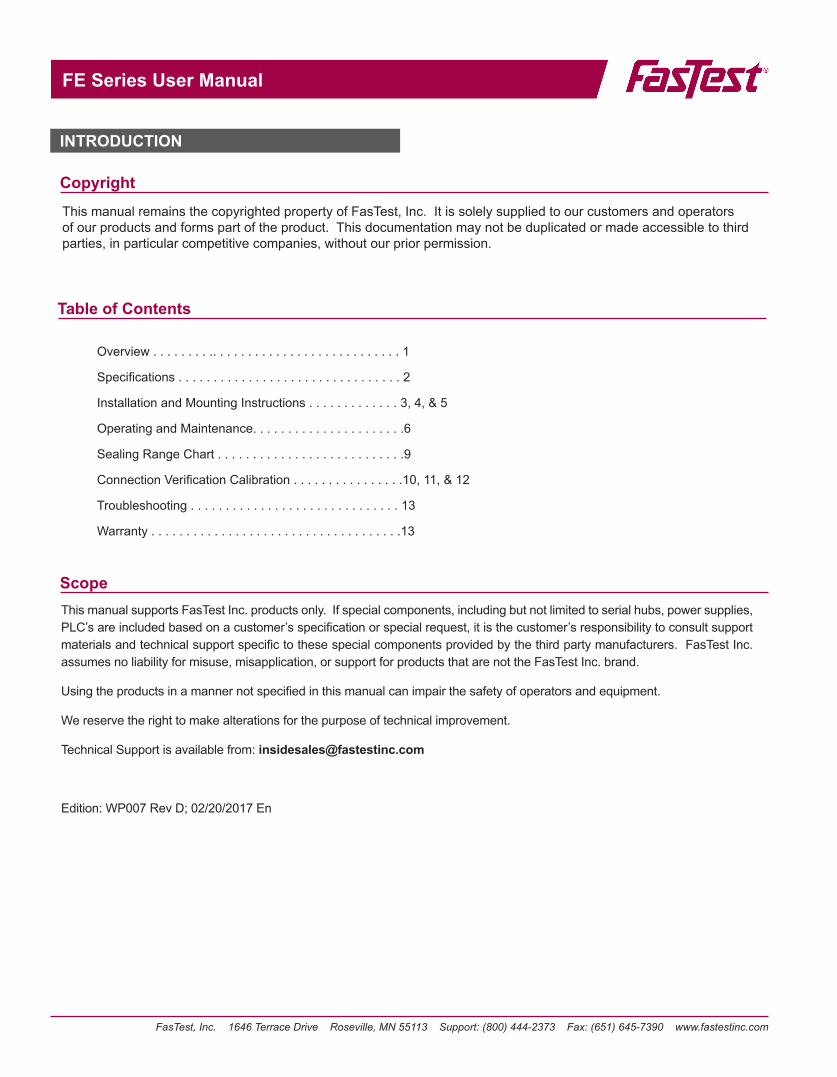
A new FE comes with the connector (1) and a seal set (2) as shown in Figure 1A. Users must install the seal set into the connector before use.
Figure 1B. Connection Verification cables
(1) FE01
(2) FES01-03Note: Seal sets contain elastomer seals and backup washers. For complete listing of seal set size ranges see catalog.
Contents:
OVERVIEW
The FE Series delivers fast, leak free connections for vacuum and pressure testing, fluid filling or flushing applications. The connector seals internally to smooth tubes or threaded ports of many materials. Compressed air activates the seals for a leak tight, non-marring connection for air and liquid applications - even with rough and oily surfaces.
The Connection Verification™ feature provides the user an indication the connector has properly actuated to a calibrated position. As pilot pressure is applied to a FE+ connector, the “piston” moves in a linear manner which compresses the Main Seal on the test piece. Connection Verification™ uses a sensor that measures internal piston travel which is calibrated to the user’s specific sealing range. After calibration, the connector will send a feedback signal each time the piston travels within the range set by the user.
Optional Features:
CONNECTION VERIFICATION
(4) CV02 Cable Set with M8
Termination, 6’(Not Included)
(3) CV01 Cable Set
with Phoenix Termination, 3’
(Included)
CV01 CV02
A new FE+ (Connection Verification) comes with only the base connector (1), seal sets are sold seperately. Users must install the seal set into the connector before use. If the connector includes Connection Verification, a CV01 cable (3) will be included, a CV02 cable will not be included. As shown in Figure 1B.
Figure 1A. FE connector and seal set
CONNECTION VERIFICATION
FasTest, Inc. 1646 Terrace Drive Roseville, MN 55113 Support: (800) 444-2373 Fax: (651) 645-7390 www.fastestinc.com
FE Series User Manual
2
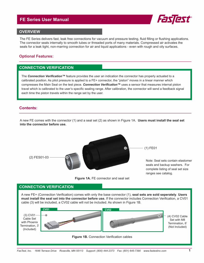
Operating Pressure 500 psi (34 bar)
Connection Profile External Tubes and Threads
Termination Profile Female 10-32” UNF, M5X8, NPT/BSPP: ⅛” to 2½”
Mounting Port Female 10-32” to ⅜-24” UNF, M5X8 to M11X1.5, 4-40” to ⅜-24” UNC
Pilot Port Female 10-32” UNF, M5X8, ⅛” NPT/BSPP
Pilot Pressure 60-600 psi
Housing Material Aluminum and Stainless steel
Seal MaterialStandard: Neoprene, UrethaneOptional: FKM (Viton), Buna-N or EPDM
Operating Temperatures0°F to 200°F (-17°C to 93°C) Neoprene32°F to 175°F (0°C to 79°C) Urethane
CHART 1: Dimensions
FE Body Sizes A B C D E F G H I J L
FE001 1.72(42.68)
.085(21.59)
⅛ NPTF 10-32 UNF 0.63(16.0)
NA4-40 UNC
NA NA NA.22
(5.58)FEM001 ⅛ BSPP M5x.8 M2.5x.45FE01 2.05
(52.1)1.49
(37.9)⅛ NPTF 10-32 UNF 1.10
(28.0).55
(14.0)10-32 UNF .54
(13.72)
.52(13.20)
.41(10.41)
.58(14.8)FEM01 ⅛ BSPP M5x.8 M5x.8
FE1 2.72(69.1)
2.22(56.4)
¼ NPTF ⅛ NPTF 1.62(41.2)
.81(20.6)
¼ - 28 UNF .770(19.56)
.61(15.5)FEM1 ¼ BSPP ⅛ BSPP M6x1
FE2 3.50(88.9)
3.11(79.0)
½ NPTF ⅛ NPTF 2.50(63.5)
1.25(31.75)
¼ - 28 UNF 1.185(30.01)
1.06(27.0)FEM2 ½ BSPP ⅛ BSPP M6x1
FE3 4.48(113.8)
4.23(107.5)
1 NPTF ⅛ NPTF 3.25(82.6)
1.63(41.5)
¼ - 28 UNF 1.5(38.1)
1.64(41.7)FEM3 1 BSPP ⅛ BSPP M6x1
FE4 4.60(116.9)
5.48(139.2)
1½ NPTF ⅛ NPTF 4.25(108.0)
2.13(54.2)
¼ - 28 UNF 2.10(53.34)
1.64(41.7)FEM4 1½ BSPP ⅛ BSPP M6x1
FE5 4.60(116.9)
6.98(178.0)
2 NPTF ⅛ NPTF 5.50(139.7)
2.75(57.2)
⅜ - 24 UNF 2.70(68.58)
1.64(41.7)FEM5 2 BSPP ⅛ BSPP M11x1.5
FE6 4.97(136.3)
7.48(190.0)
2½ NPTF ⅛ NPTF 6.12(155.5)
3.06(77.8)
⅜ - 24 UNF 3.05(77.47)
1.64(41.7)FEM6 2½ BSPP ⅛ BSPP M11x1.5
Figure 2. Connector Dimensional Features
Standard FE
NPN (max 100 mA load)
Supply voltage range: 8V to 24V
Over-voltage protection
Sealed electronics
Internal memory stores calibration points
CV
CV01 CV02
SPECIFICATIONS
CV01: .46” Wide X .20” Tall
CV02:M8 Ø = .41”
FasTest, Inc. 1646 Terrace Drive Roseville, MN 55113 Support: (800) 444-2373 Fax: (651) 645-7390 www.fastestinc.com
FE Series User Manual
3
Standard and Connection Verification versions: read and understand each of the following procedures before operating the connector:
A. Installation of SealsB. Mounting the ConnectorC. Attachment of Pilot Pressure and Test Media Supply LinesD. Connector Operation
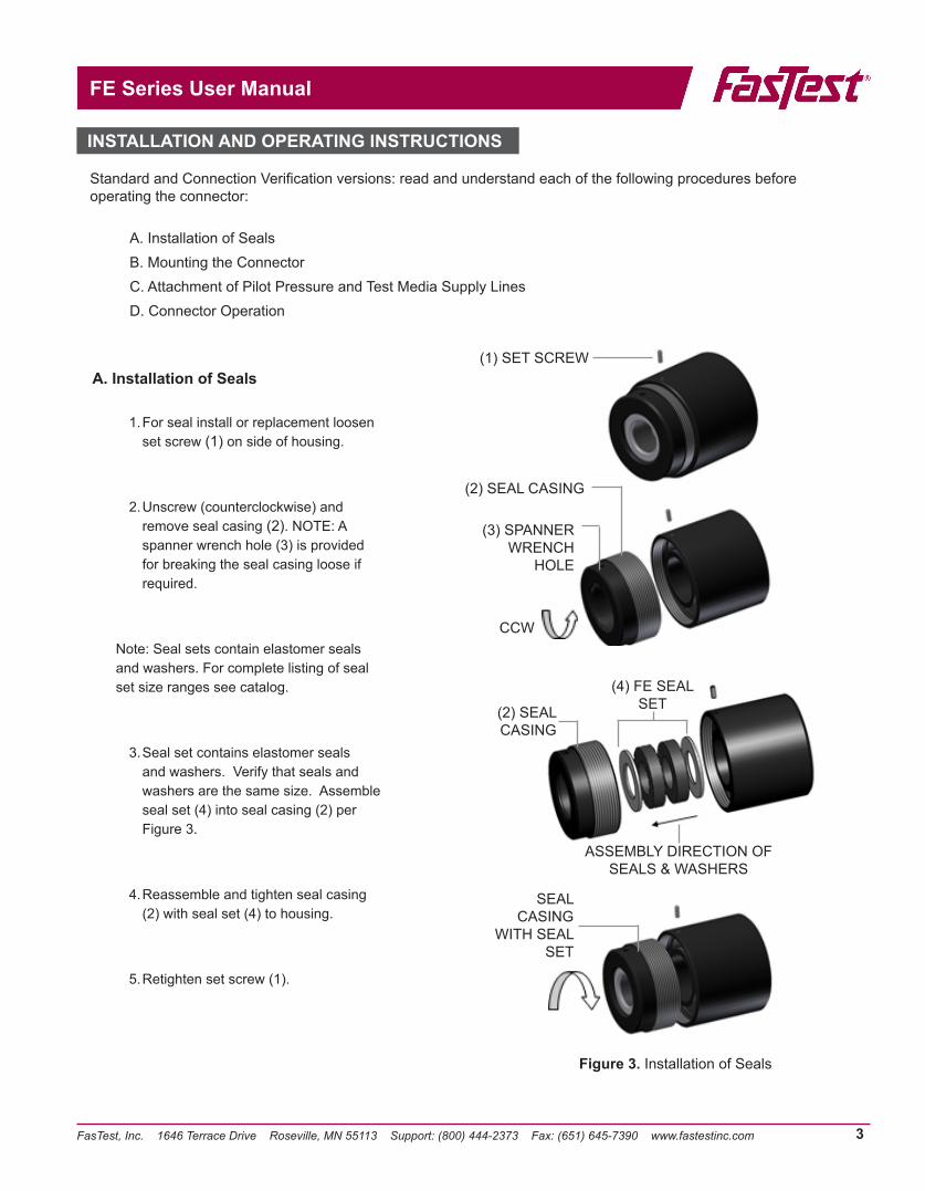
A. Installation of Seals
1. For seal install or replacement loosen set screw (1) on side of housing.
2. Unscrew (counterclockwise) and remove seal casing (2). NOTE: A spanner wrench hole (3) is provided for breaking the seal casing loose if required.
Note: Seal sets contain elastomer seals and washers. For complete listing of seal set size ranges see catalog.
3. Seal set contains elastomer seals and washers. Verify that seals and washers are the same size. Assemble seal set (4) into seal casing (2) per Figure 3.
4. Reassemble and tighten seal casing (2) with seal set (4) to housing.
5. Retighten set screw (1).
(1) SET SCREW
(3) SPANNER WRENCH
HOLE
CCW
SEAL CASING
WITH SEAL SET
(4) FE SEAL SET
ASSEMBLY DIRECTION OF SEALS & WASHERS
(2) SEAL CASING
Figure 3. Installation of Seals
(2) SEAL CASING
INSTALLATION AND OPERATING INSTRUCTIONS
FasTest, Inc. 1646 Terrace Drive Roseville, MN 55113 Support: (800) 444-2373 Fax: (651) 645-7390 www.fastestinc.com
FE Series User Manual
4
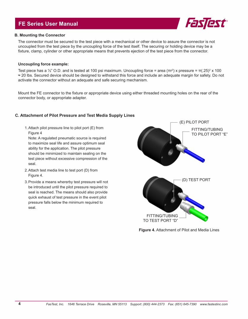
1. Attach pilot pressure line to pilot port (E) from Figure 4 Note: A regulated pneumatic source is required to maximize seal life and assure optimum seal ability for the application. The pilot pressure should be minimized to maintain sealing on the test piece without excessive compression of the seal.
2. Attach test media line to test port (D) from Figure 4.
3. Provide a means whererby test pressure will not be introduced until the pilot pressure required to seal is reached. The means should also provide quick exhaust of test pressure in the event pilot pressure falls below the minimum required to seal.
B. Mounting the ConnectorThe connector must be secured to the test piece with a mechanical or other device to assure the connector is not uncoupled from the test piece by the uncoupling force of the test itself. The securing or holding device may be a fixture, clamp, cylinder or other appropriate means that prevents ejection of the test piece from the connector.
Uncoupling force example:Test piece has a ½” O.D. and is tested at 100 psi maximum. Uncoupling force = area (πr2) x pressure = π(.25)2 x 100 ≈ 20 lbs. Secured device should be designed to withstand this force and include an adequate margin for safety. Do not activate the connector without an adequate and safe securing mechanism.
Mount the FE connector to the fixture or appropriate device using either threaded mounting holes on the rear of the connector body, or appropriate adapter.
FITTING/TUBING TO PILOT PORT “E”
FITTING/TUBING TO TEST PORT “D”
Figure 4. Attachment of Pilot and Media Lines
C. Attachment of Pilot Pressure and Test Media Supply Lines(E) PILOT PORT
(D) TEST PORT
FasTest, Inc. 1646 Terrace Drive Roseville, MN 55113 Support: (800) 444-2373 Fax: (651) 645-7390 www.fastestinc.com
FE Series User Manual
5
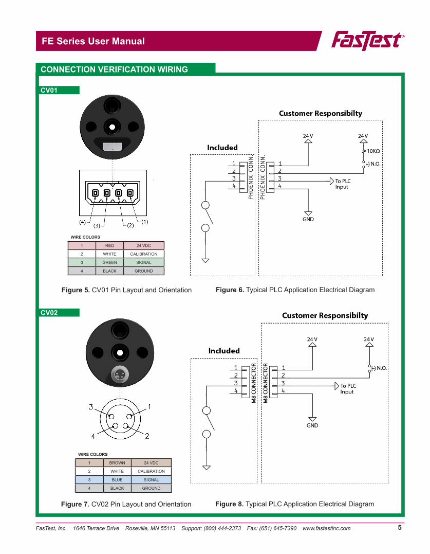
Figure 5. CV01 Pin Layout and Orientation Figure 6. Typical PLC Application Electrical Diagram
WIRE COLORS
1 RED 24 VDC
2 WHITE CALIBRATION
3 GREEN SIGNAL
4 BLACK GROUND
WIRE COLORS
1 BROWN 24 VDC
2 WHITE CALIBRATION
3 BLUE SIGNAL
4 BLACK GROUND
CONNECTION VERIFICATION WIRING
CV01
CV02
Figure 7. CV02 Pin Layout and Orientation Figure 8. Typical PLC Application Electrical Diagram
FasTest, Inc. 1646 Terrace Drive Roseville, MN 55113 Support: (800) 444-2373 Fax: (651) 645-7390 www.fastestinc.com
FE Series User Manual
6
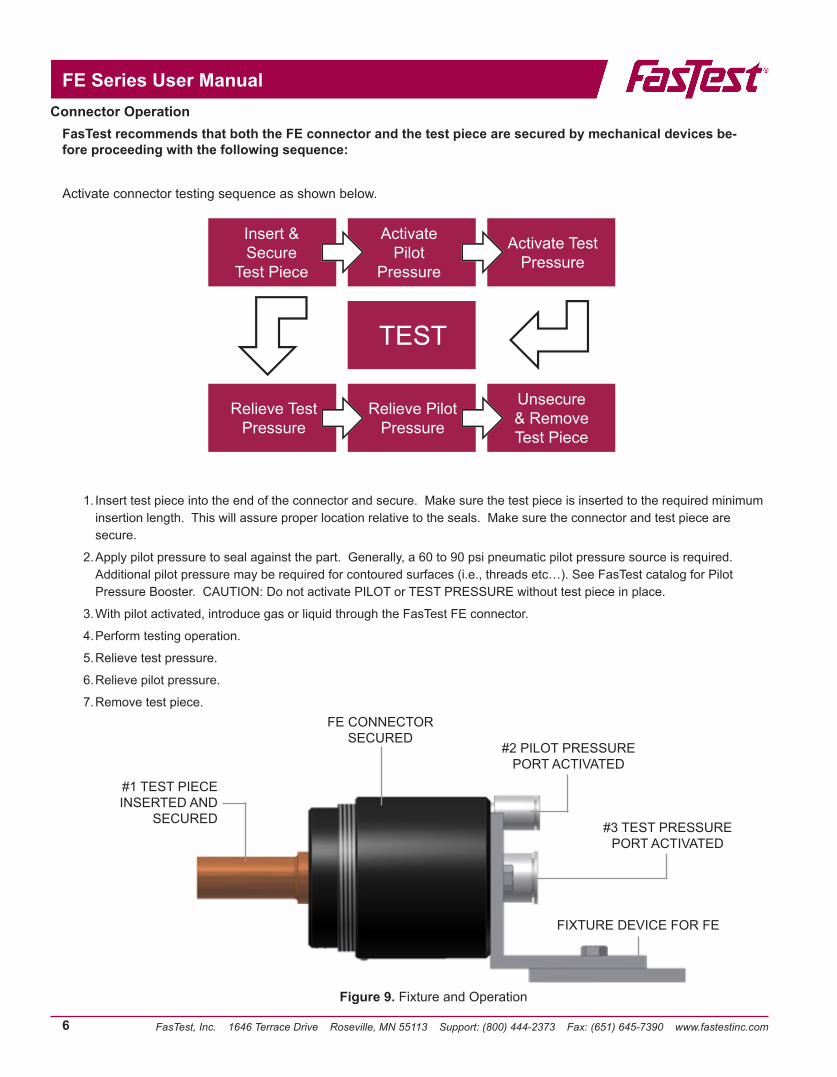
Connector OperationFasTest recommends that both the FE connector and the test piece are secured by mechanical devices be-fore proceeding with the following sequence:
Activate connector testing sequence as shown below.
Insert & Secure
Test Piece
Activate Pilot
Pressure
Activate Test Pressure
TEST
Relieve Test Pressure
Relieve Pilot Pressure
Unsecure & Remove Test Piece
1. Insert test piece into the end of the connector and secure. Make sure the test piece is inserted to the required minimum insertion length. This will assure proper location relative to the seals. Make sure the connector and test piece are secure.
2. Apply pilot pressure to seal against the part. Generally, a 60 to 90 psi pneumatic pilot pressure source is required. Additional pilot pressure may be required for contoured surfaces (i.e., threads etc…). See FasTest catalog for Pilot Pressure Booster. CAUTION: Do not activate PILOT or TEST PRESSURE without test piece in place.
3. With pilot activated, introduce gas or liquid through the FasTest FE connector.
4. Perform testing operation.
5. Relieve test pressure.
6. Relieve pilot pressure.
7. Remove test piece.
Figure 9. Fixture and Operation
#1 TEST PIECE INSERTED AND
SECURED
FE CONNECTOR SECURED
#2 PILOT PRESSURE PORT ACTIVATED
#3 TEST PRESSURE PORT ACTIVATED
FIXTURE DEVICE FOR FE
FasTest, Inc. 1646 Terrace Drive Roseville, MN 55113 Support: (800) 444-2373 Fax: (651) 645-7390 www.fastestinc.com
FE Series User Manual
7
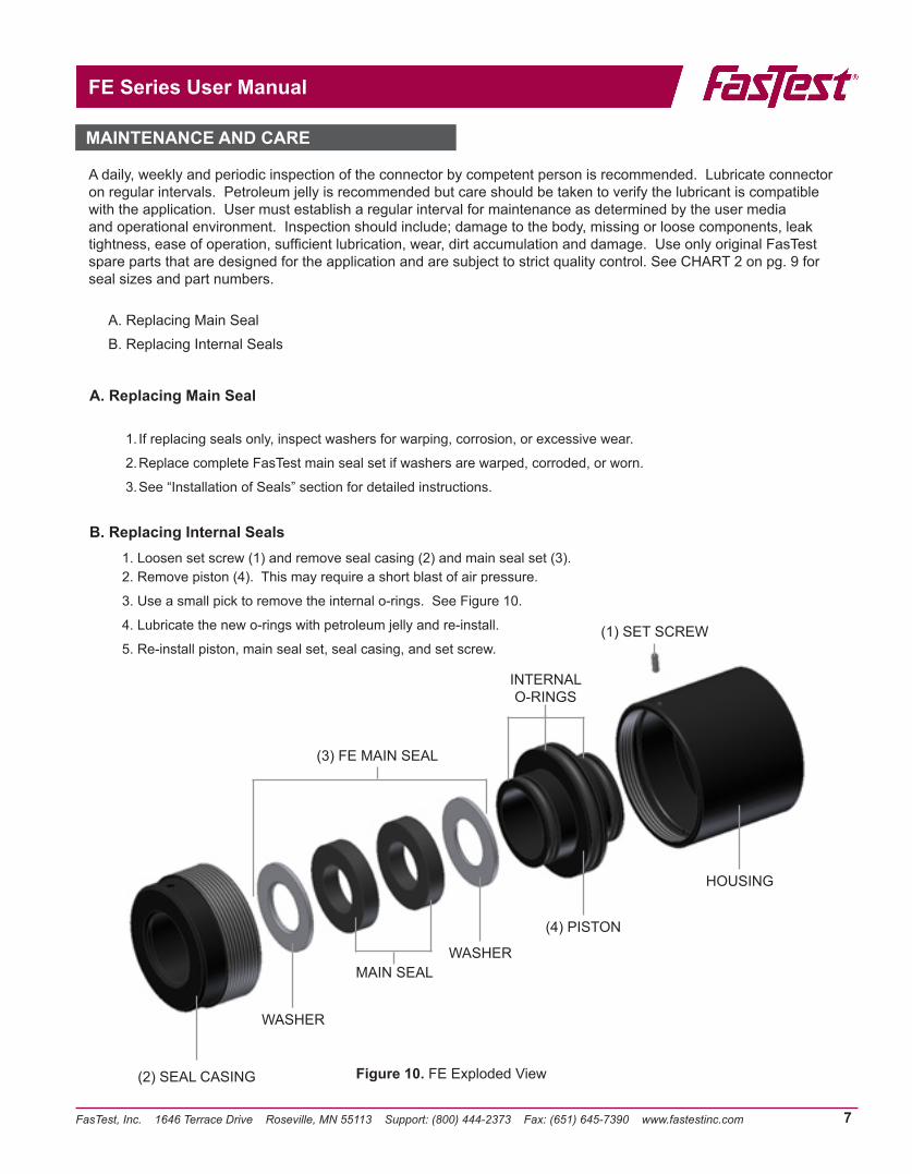
A daily, weekly and periodic inspection of the connector by competent person is recommended. Lubricate connector on regular intervals. Petroleum jelly is recommended but care should be taken to verify the lubricant is compatible with the application. User must establish a regular interval for maintenance as determined by the user media and operational environment. Inspection should include; damage to the body, missing or loose components, leak tightness, ease of operation, sufficient lubrication, wear, dirt accumulation and damage. Use only original FasTest spare parts that are designed for the application and are subject to strict quality control. See CHART 2 on pg. 9 for seal sizes and part numbers.
A. Replacing Main SealB. Replacing Internal Seals
A. Replacing Main Seal
1. If replacing seals only, inspect washers for warping, corrosion, or excessive wear.
2. Replace complete FasTest main seal set if washers are warped, corroded, or worn.
3. See “Installation of Seals” section for detailed instructions.
B. Replacing Internal Seals1. Loosen set screw (1) and remove seal casing (2) and main seal set (3).2. Remove piston (4). This may require a short blast of air pressure.
3. Use a small pick to remove the internal o-rings. See Figure 10.
4. Lubricate the new o-rings with petroleum jelly and re-install.
5. Re-install piston, main seal set, seal casing, and set screw.
(2) SEAL CASING
WASHER
MAIN SEALWASHER
(4) PISTON
HOUSING
INTERNAL O-RINGS
(3) FE MAIN SEAL
(1) SET SCREW
Figure 10. FE Exploded View
MAINTENANCE AND CARE
FasTest, Inc. 1646 Terrace Drive Roseville, MN 55113 Support: (800) 444-2373 Fax: (651) 645-7390 www.fastestinc.com
FE Series User Manual
8
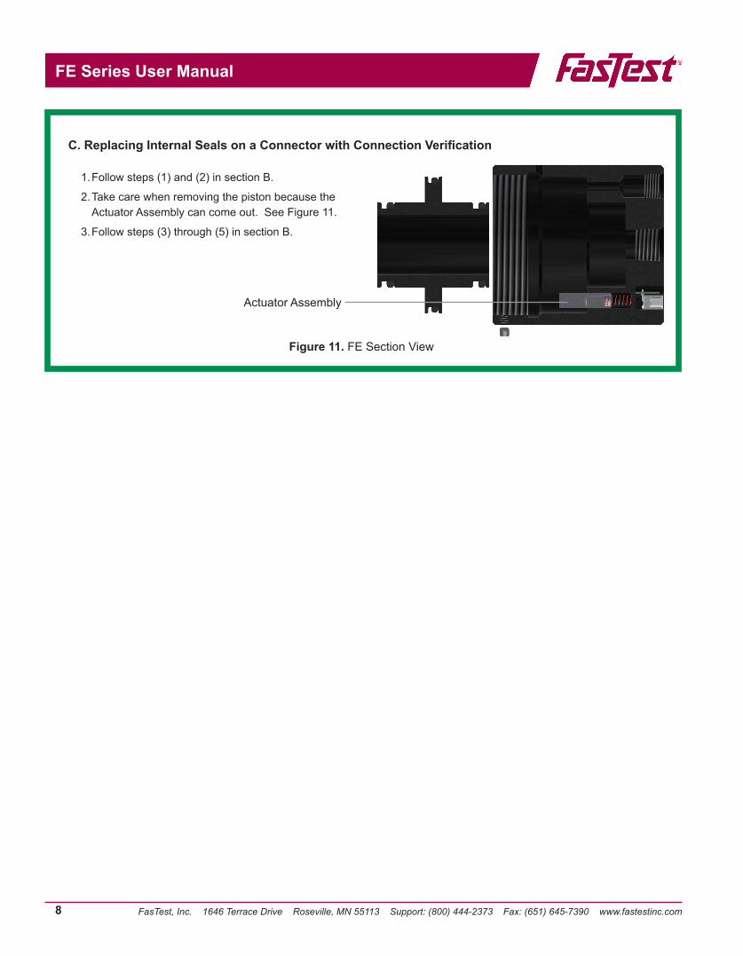
1. Follow steps (1) and (2) in section B.
2. Take care when removing the piston because the Actuator Assembly can come out. See Figure 11.
3. Follow steps (3) through (5) in section B.
Actuator Assembly
C. Replacing Internal Seals on a Connector with Connection Verification
Figure 11. FE Section View

FasTest, Inc. 1646 Terrace Drive Roseville, MN 55113 Support: (800) 444-2373 Fax: (651) 645-7390 www.fastestinc.com
FE Series User Manual
9
Model FES Seal Set Sealing Range No. of Seals
FE001FES001-0050FES001-001FES001-002
.030 - .050
.050 - .080
.080 - .130
111
FE01
FES01-01FES01-02FES01-03FES01-04FES01-05
FES01-1/8NPT
.100 - .180180 - .260.260 - .340.340 - .420.420 - .510
1/8 NPT
111111
FE1
FE1-15FE1-16FE1-17FE1-18FE1-19
FE1-1/4NPTFE1-3/8NPT
.433 - .512
.512 - .591
.591 - .669
.669 - .750
.750 - .8271/4 NPT3/8 NPT
1111111
FE2
FE2-21 .787 - .866 2FE2-22 .866 - .945 2FE2-23 .945 - 1.204 2FE2-24 1.024 - 1.102 2FE2-25 1.102 - 1.181 2FE2-26 1.181 - 1.260 2FE2-27 1.260 - 1.339 2FE2-28 1.339 - 1.417 2FE2-29 1.417 - 1.510 2
FE2-1/2NPT 1/2 NPT 1FE2-3/4NPT 3/4 NPT 1FE2-1NPT 1 NPT 1
Model FES Seal Set Sealing Range No. of Seals
FE3
FE3-31 1.496 - 1.614 3FE3-32 1.614 - 1.732 3FE3-33 1.732 - 1.850 3FE3-34 1.850 - 1.969 3
FE3-1 1/2NPT 1-1/4 NPT 1FE3-1 1/2NPT 1-1/2 NPT 1
FE4
FE4-41 1.960 - 2.087 3FE4-42 2.087 - 2.205 3FE4-43 2.205 - 2.323 3FE4-44 2.323 - 2.441 3FE4-45 2.441 - 2.559 3FE4-46 2.559 - 2.677 3FE4-47 2.677 - 2.795 3FE4-48 2.795 - 2.913 3FE4-49 2.913 - 3.032 3
FE4-2NPT 2 NPT 1
FE5
FE5-51 2.970 - 3.100 3FE5-52 3.100 - 3.230 3FE5-53 3.230 - 3.360 3FE5-54 3.360 - 3.490 3FE5-55 3.490 - 3.620 3FE5-56 3.620 - 3.750 3FE5-57 3.750 - 3.880 3FE5-58 3.880 - 4.010 3FE5-59 4.010 - 4.130 3
FE6
FE6-61FE6-62FE6-63FE6-64FE6-65FE6-66FE6-67
4.130 – 4.2604.260 – 4.3904.390 – 4.5204.520 – 4.6504.650 – 4.7804.780 – 4.8104.910 – 5.040
3333333
CHART 2: Connector Sealing Range
z Note: Standard main seal material is Neoprene. NPT seals are Urethane. NPT seal sets require pilot pressure booster. Use of less than the listed number of seals (for less insertion depth) requires a spacer. See FasTest catalog. Seal Installation Instructions included with seal sets.
FasTest, Inc. 1646 Terrace Drive Roseville, MN 55113 Support: (800) 444-2373 Fax: (651) 645-7390 www.fastestinc.com
FE Series User Manual
10
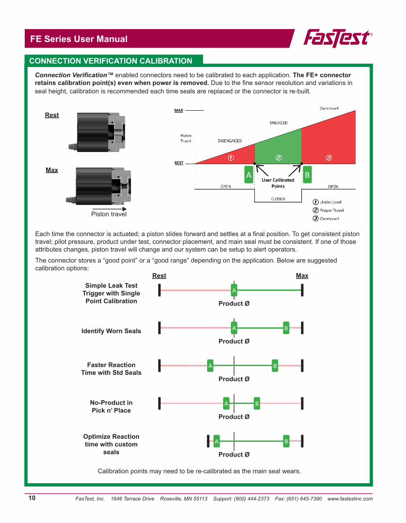
Connection Verification™ enabled connectors need to be calibrated to each application. The FE+ connector retains calibration point(s) even when power is removed. Due to the fine sensor resolution and variations in seal height, calibration is recommended each time seals are replaced or the connector is re-built.
Each time the connector is actuated; a piston slides forward and settles at a final position. To get consistent piston travel; pilot pressure, product under test, connector placement, and main seal must be consistent. If one of those attributes changes, piston travel will change and our system can be setup to alert operators.
The connector stores a “good point” or a “good range” depending on the application. Below are suggested calibration options:
A B
Simple Leak Test Trigger with Single Point Calibration Product Ø
Identify Worn SealsProduct Ø
Faster Reaction Time with Std Seals
Product Ø
No-Product in Pick n’ Place
Product Ø
Optimize Reaction time with custom
seals Product Ø
Rest
A
A B
A B
A B
A B
Max
CONNECTION VERIFICATION CALIBRATION
Calibration points may need to be re-calibrated as the main seal wears.
Rest
Max
Piston travel
FasTest, Inc. 1646 Terrace Drive Roseville, MN 55113 Support: (800) 444-2373 Fax: (651) 645-7390 www.fastestinc.com
FE Series User Manual
11
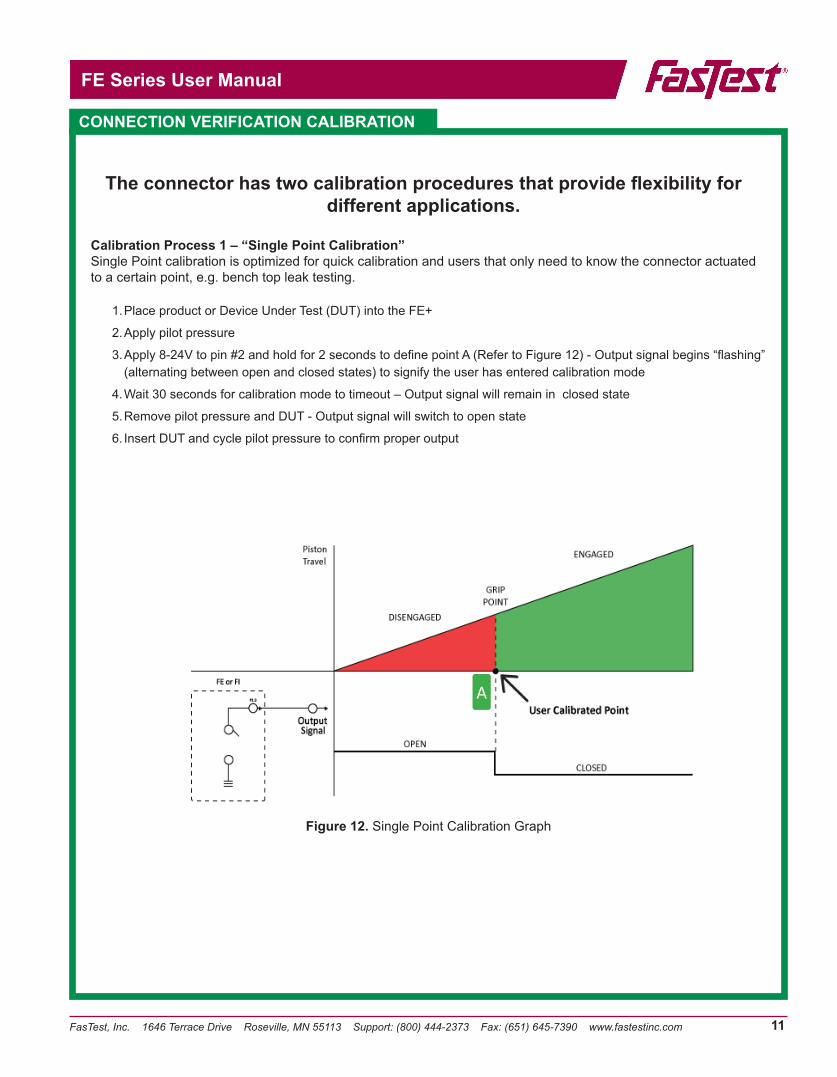
The connector has two calibration procedures that provide flexibility for different applications.
Calibration Process 1 – “Single Point Calibration”Single Point calibration is optimized for quick calibration and users that only need to know the connector actuated to a certain point, e.g. bench top leak testing.
1. Place product or Device Under Test (DUT) into the FE+
2. Apply pilot pressure
3. Apply 8-24V to pin #2 and hold for 2 seconds to define point A (Refer to Figure 12) - Output signal begins “flashing” (alternating between open and closed states) to signify the user has entered calibration mode
4. Wait 30 seconds for calibration mode to timeout – Output signal will remain in closed state
5. Remove pilot pressure and DUT - Output signal will switch to open state
6. Insert DUT and cycle pilot pressure to confirm proper output
Figure 12. Single Point Calibration Graph
CONNECTION VERIFICATION CALIBRATION
A
FasTest, Inc. 1646 Terrace Drive Roseville, MN 55113 Support: (800) 444-2373 Fax: (651) 645-7390 www.fastestinc.com
FE Series User Manual
12
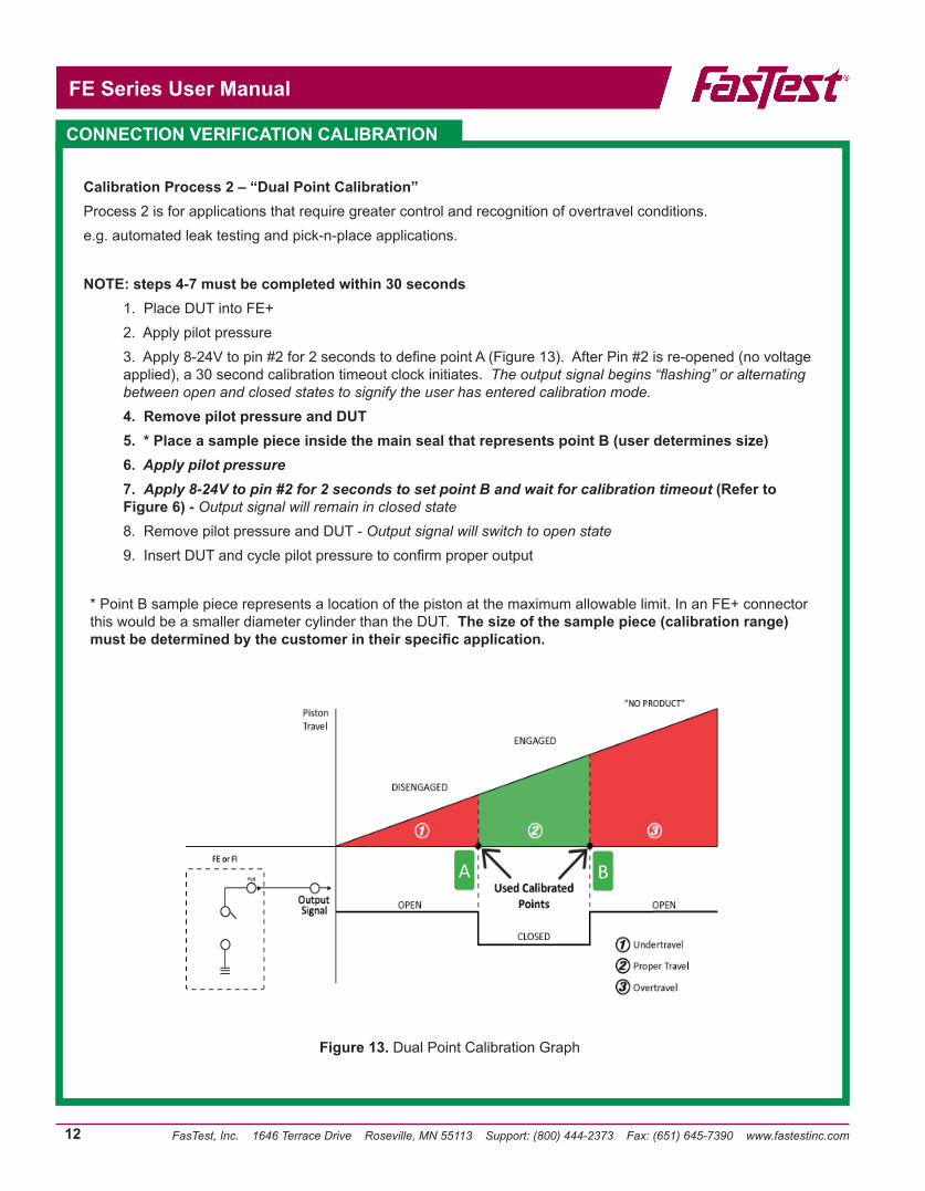
Calibration Process 2 – “Dual Point Calibration”Process 2 is for applications that require greater control and recognition of overtravel conditions. e.g. automated leak testing and pick-n-place applications.
NOTE: steps 4-7 must be completed within 30 seconds1. Place DUT into FE+ 2. Apply pilot pressure3. Apply 8-24V to pin #2 for 2 seconds to define point A (Figure 13). After Pin #2 is re-opened (no voltage applied), a 30 second calibration timeout clock initiates. The output signal begins “flashing” or alternating between open and closed states to signify the user has entered calibration mode.4. Remove pilot pressure and DUT5. * Place a sample piece inside the main seal that represents point B (user determines size)6. Apply pilot pressure7. Apply 8-24V to pin #2 for 2 seconds to set point B and wait for calibration timeout (Refer to Figure 6) - Output signal will remain in closed state8. Remove pilot pressure and DUT - Output signal will switch to open state9. Insert DUT and cycle pilot pressure to confirm proper output
* Point B sample piece represents a location of the piston at the maximum allowable limit. In an FE+ connector this would be a smaller diameter cylinder than the DUT. The size of the sample piece (calibration range) must be determined by the customer in their specific application.
Figure 13. Dual Point Calibration Graph
CONNECTION VERIFICATION CALIBRATION
A B
FasTest, Inc. 1646 Terrace Drive Roseville, MN 55113 Support: (800) 444-2373 Fax: (651) 645-7390 www.fastestinc.com
FE Series User Manual
13
FasTest Inc. warrants its products against defects in workmanship and materials for 12 months from the date of sale by FasTest Inc. or its authorized distributor. This warranty is void if the product is misused, tampered with or used in a manner that is contrary to FasTest Inc.’s written recommendations and/or instructions.
FasTest Inc. does not warrant the suitability of the product for any particular application. Determining product application suitability is solely the customer’s responsibility. FasTest Inc. is not liable for consequential or other damages including, but not limited to, loss, damage, personal injury, or any other expense directly or indirectly arising from the use of or inability to use its products either separately or in combination with other products.
ALL OTHER WARRANTIES EXPRESS OR IMPLIED, WHETHER ORAL, WRITTEN OR IN ANY OTHER FORM, INCLUDING BUT NOT LIMITED TO WARRANTIES OF MERCHANTABILITY OR FITNESS FOR A PARTICULAR PURPOSE ARE EXPRESSLY EXCLUDED.
The sole and exclusive remedy under this warranty is limited to replacement of the product or an account credit in the amount of the original selling price, at the option of FasTest Inc. All allegedly defective products must be returned prepaid transportation to FasTest Inc., together with information describing the product’s performance, unless disposition in the field is authorized in writing by FasTest Inc.
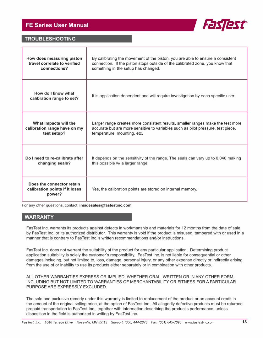
How does measuring piston travel correlate to verified
connections?
By calibrating the movement of the piston, you are able to ensure a consistent connection. If the piston stops outside of the calibrated zone, you know that something in the setup has changed.
How do I know what calibration range to set? It is application dependent and will require investigation by each specific user.
What impacts will the calibration range have on my
test setup?
Larger range creates more consistent results, smaller ranges make the test more accurate but are more sensitive to variables such as pilot pressure, test piece, temperature, mounting, etc.
Do I need to re-calibrate after changing seals?
It depends on the sensitivity of the range. The seals can vary up to 0.040 making this possible w/ a larger range.
Does the connector retain calibration points if it loses
power?Yes, the calibration points are stored on internal memory.
For any other questions, contact: [email protected]
TROUBLESHOOTING
WARRANTY

FasTest, Inc. 1646 Terrace Drive Roseville, MN 55113 Support: (800) 444-2373 Fax: (651) 645-7390 www.fastestinc.com
FE Series User Manual
14
NOTES