Embed Size (px)
DESCRIPTION
Feature CAM Brochure
Citation preview
FeatureCAM 2012 R2
What's New
Copyright © 1995-2012 Delcam plc. All rights reserved.
Delcam plc has no control over the use made of the software described in this manual and cannot accept responsibility for any
loss or damage howsoever caused as a result of using the software. Users are advised that all the results from the software should be
checked by a competent person, in accordance with good quality control procedures.
The functionality and user interface in this manual is subject to change without notice in future revisions of software.
The software described in this manual is furnished under licence agreement and may be used or copied solely in accordance with the
terms of such licence.
Delcam plc grants permission for licensed users to print copies of this manual or portions of this manual for personal use only.
Schools, colleges and universities that are licensed to use the software may make copies of this manual or portions of this manual
for students currently registered for classes where the software is used.
Acknowledgements
This documentation references a number of registered trademarks and these are the property of their respective owners. For example,
Microsoft and Windows are either registered trademarks or trademarks of Microsoft Corporation in the United States.
FeatureCAM Version: 2012 R2 Date: 05 January 2012 11:09
FeatureCAM 2012 R2 What's New Contents • i
Contents
What's New in FeatureCAM 2012 1
User interface: More isometric views .................................................................. 1 User interface: Keyboard shortcuts ..................................................................... 3
User interface: Part view multiple select ............................................................. 4 Tooling: Better Face Mill tools ............................................................................. 5
Tooling: Cutting data by tool ............................................................................... 6 Tool cutting data example .......................................................................... 8 Depth of cut precedence .......................................................................... 13
2.5D: Total stock for finish pass ........................................................................ 17 2.5D: Toolpath feature improvements ............................................................... 18
2.5D: Exact Z step ............................................................................................ 22
2.5D: Back Bore holes ...................................................................................... 24 Simulation: Part compare extended .................................................................. 25 3D: Z-level spiral roughing ................................................................................ 27
Turn: Solid model as tool holder ....................................................................... 28 Solid tool holder example ......................................................................... 29
Turn: Better tool holder graphics ....................................................................... 36
Turning leave allowance ................................................................................... 37
What's New in FeatureCAM 2012 R2 38
Network database: Shared machining configurations ....................................... 38
Import improvements ........................................................................................ 40 User interface: Copy and paste from PowerSHAPE ......................................... 40
2.5D: New technology (NT) toolpaths ............................................................... 40 Differences between NT and traditional toolpaths .................................... 45 Better Minimize tool retract with NT toolpaths .......................................... 46
2.5D: Separate lead-in and lead-out distances ................................................. 50 2.5D: Thread Mill tool hand ............................................................................... 51
2.5D: Face Mill tools for Chamfers .................................................................... 52
2.5D: Hole cycle G74 and G88 ......................................................................... 52
3D: Z-level finish: Flat surface support.............................................................. 53 3D: Save boundary curve ................................................................................. 54 5-axis: Turn/Mill B-axis alternative position ....................................................... 55 Simulation: Step backward ............................................................................... 55 Simulation: Faster 3D simulation ...................................................................... 55
Simulation: New keyboard shortcuts ................................................................. 56 Machine simulation: Better collision display ...................................................... 56 Turn/Mill: Cylindrical interpolation support ........................................................ 56 XBUILD: Use Delcam post processor files ........................................................ 57 Probing: UDF available ..................................................................................... 57

ii • Contents FeatureCAM 2012 R2 What's New
API: New functions ........................................................................................... 58
Other improvements ......................................................................................... 58
Index 59
FeatureCAM 2012 R2 What's New What's New in FeatureCAM 2012 • 1
FeatureCAM 2012 offers all of the original features of FeatureCAM
2011 R3 (V17.8), but with numerous improvements. The most significant improvements are detailed in the following topics.
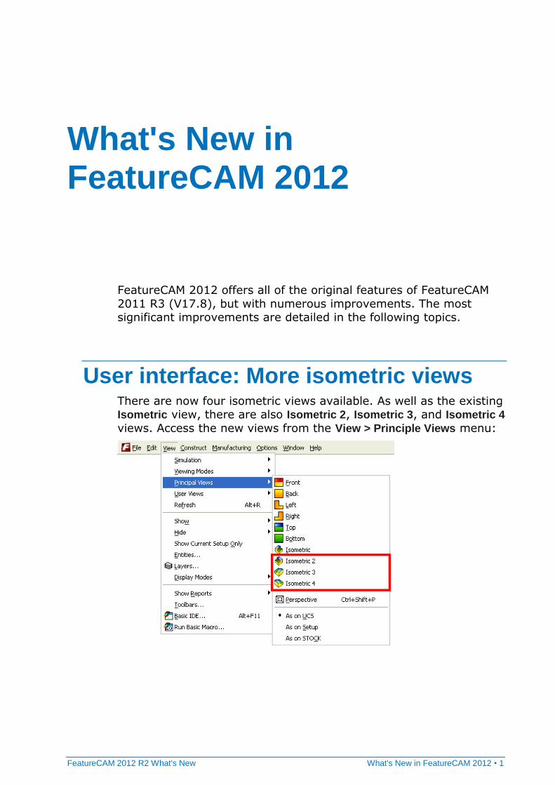
User interface: More isometric views There are now four isometric views available. As well as the existing Isometric view, there are also Isometric 2, Isometric 3, and Isometric 4
views. Access the new views from the View > Principle Views menu:
What's New in FeatureCAM 2012
2 • What's New in FeatureCAM 2012 FeatureCAM 2012 R2 What's New
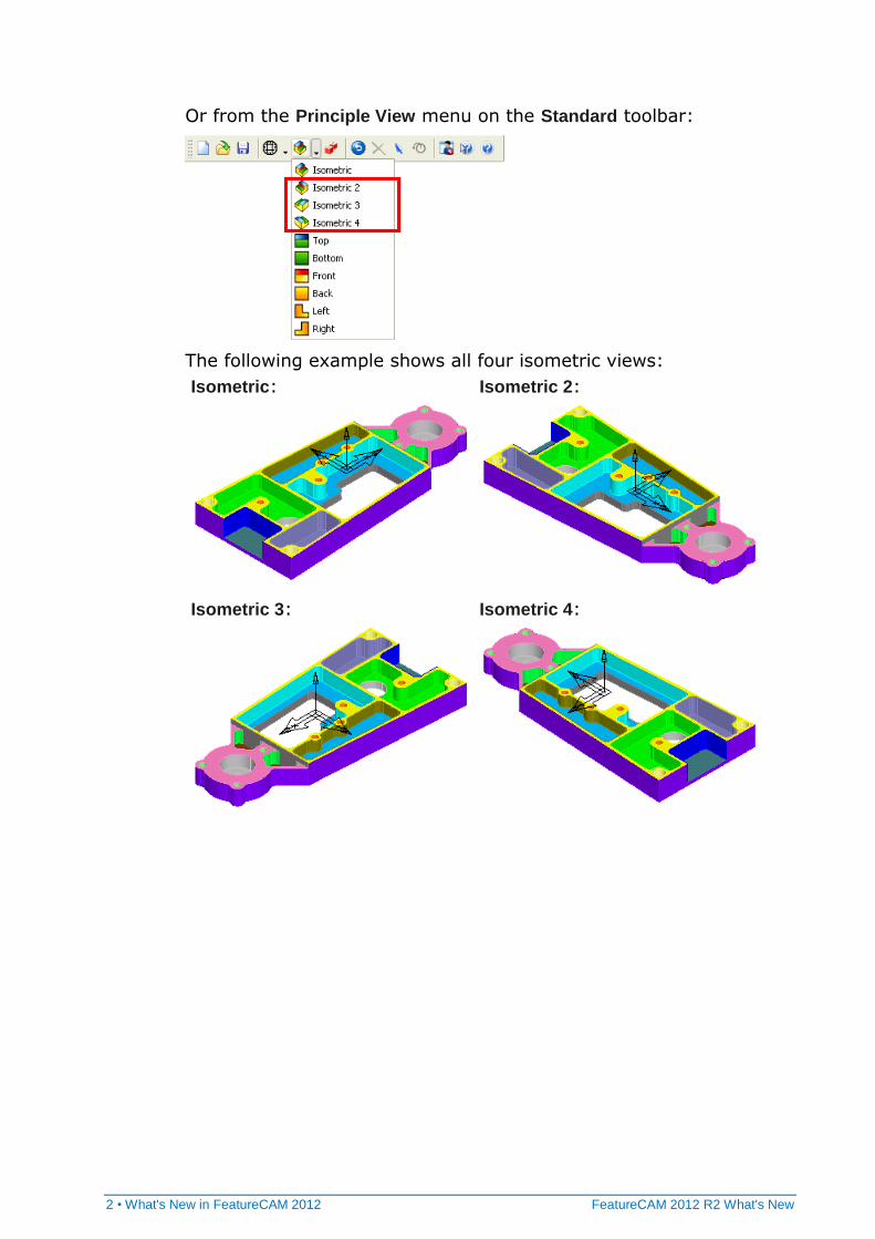
Or from the Principle View menu on the Standard toolbar:
The following example shows all four isometric views:
Isometric:
Isometric 2:
Isometric 3:
Isometric 4:
FeatureCAM 2012 R2 What's New What's New in FeatureCAM 2012 • 3
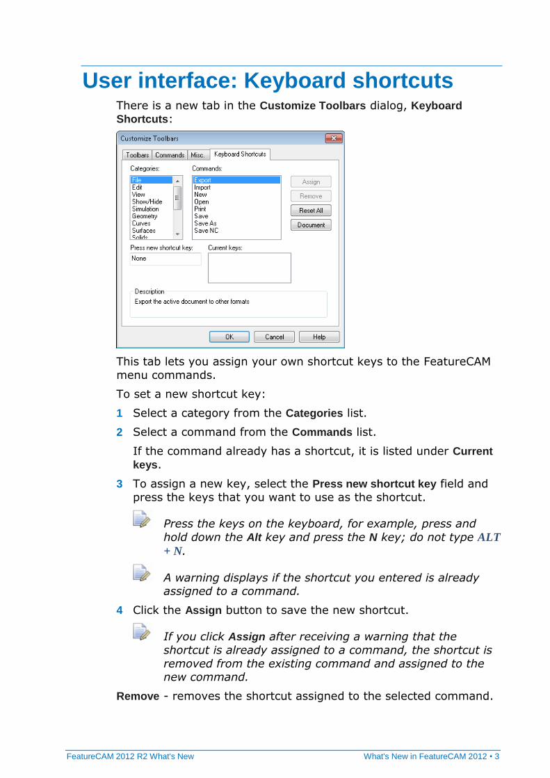
User interface: Keyboard shortcuts There is a new tab in the Customize Toolbars dialog, Keyboard
Shortcuts:
This tab lets you assign your own shortcut keys to the FeatureCAM
menu commands.
To set a new shortcut key:
1 Select a category from the Categories list.
2 Select a command from the Commands list.
If the command already has a shortcut, it is listed under Current
keys.
3 To assign a new key, select the Press new shortcut key field and
press the keys that you want to use as the shortcut.
Press the keys on the keyboard, for example, press and
hold down the Alt key and press the N key; do not type ALT
+ N.
A warning displays if the shortcut you entered is already assigned to a command.
4 Click the Assign button to save the new shortcut.
If you click Assign after receiving a warning that the
shortcut is already assigned to a command, the shortcut is
removed from the existing command and assigned to the new command.
Remove - removes the shortcut assigned to the selected command.
4 • What's New in FeatureCAM 2012 FeatureCAM 2012 R2 What's New
Reset All - resets all shortcuts to the FeatureCAM defaults.
Document - opens a *.txt file, containing a list of the current
shortcuts, in your text editor. You can print or save this file.
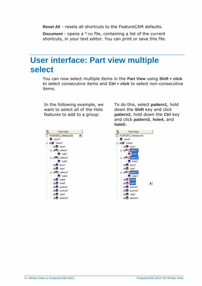
User interface: Part view multiple select
You can now select multiple items in the Part View using Shift + click
to select consecutive items and Ctrl + click to select non-consecutive
items.
In the following example, we want to select all of the Hole
features to add to a group:
To do this, select pattern1, hold down the Shift key and click
pattern2, hold down the Ctrl key
and click pattern3, hole4, and hole5:
FeatureCAM 2012 R2 What's New What's New in FeatureCAM 2012 • 5
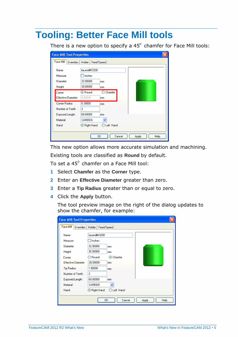
Tooling: Better Face Mill tools There is a new option to specify a 45 chamfer for Face Mill tools:
This new option allows more accurate simulation and machining.
Existing tools are classified as Round by default.
To set a 45 chamfer on a Face Mill tool:
1 Select Chamfer as the Corner type.
2 Enter an Effective Diameter greater than zero.
3 Enter a Tip Radius greater than or equal to zero.
4 Click the Apply button.
The tool preview image on the right of the dialog updates to show the chamfer, for example:
6 • What's New in FeatureCAM 2012 FeatureCAM 2012 R2 What's New
Tooling: Cutting data by tool In FeatureCAM 2012 R2, you can associate cutting data with individual tools in the tool database at two levels:
On the Overrides tab of the Tool Properties dialog. You can set
cutting data for the tool for all materials and operations.
On the Feed/Speeds tab of the Tool Properties dialog. You can set
cutting conditions by material, operation, and cut type. These override any settings on the Overrides tab.
You can override these settings at feature operation level.
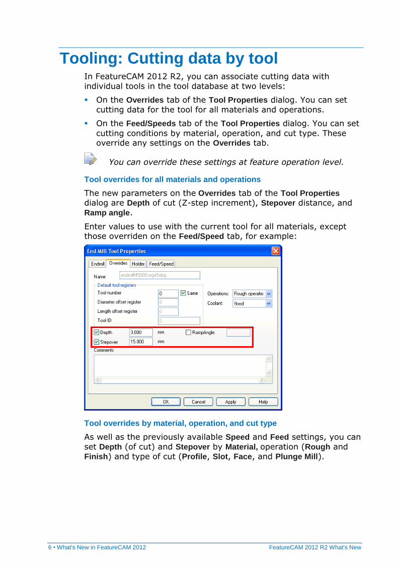
Tool overrides for all materials and operations
The new parameters on the Overrides tab of the Tool Properties dialog are Depth of cut (Z-step increment), Stepover distance, and
Ramp angle.
Enter values to use with the current tool for all materials, except those overriden on the Feed/Speed tab, for example:
Tool overrides by material, operation, and cut type
As well as the previously available Speed and Feed settings, you can
set Depth (of cut) and Stepover by Material, operation (Rough and Finish) and type of cut (Profile, Slot, Face, and Plunge Mill).
FeatureCAM 2012 R2 What's New What's New in FeatureCAM 2012 • 7
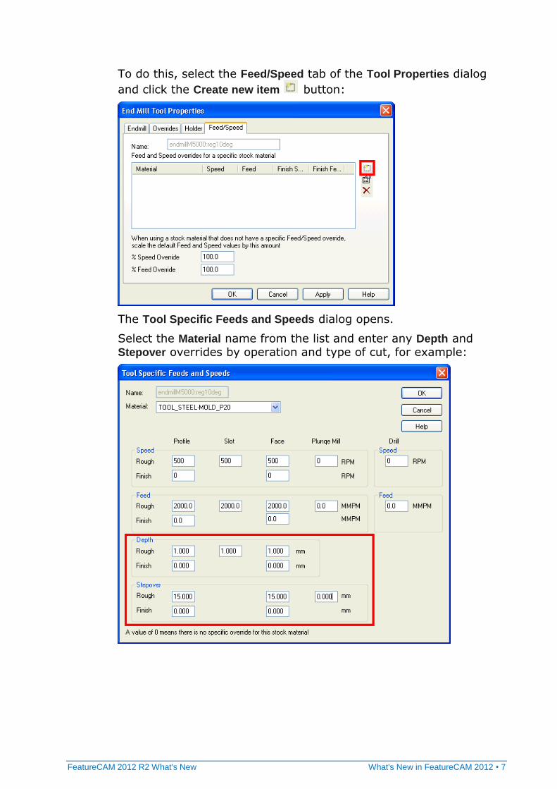
To do this, select the Feed/Speed tab of the Tool Properties dialog
and click the Create new item button:
The Tool Specific Feeds and Speeds dialog opens.
Select the Material name from the list and enter any Depth and Stepover overrides by operation and type of cut, for example:
8 • What's New in FeatureCAM 2012 FeatureCAM 2012 R2 What's New
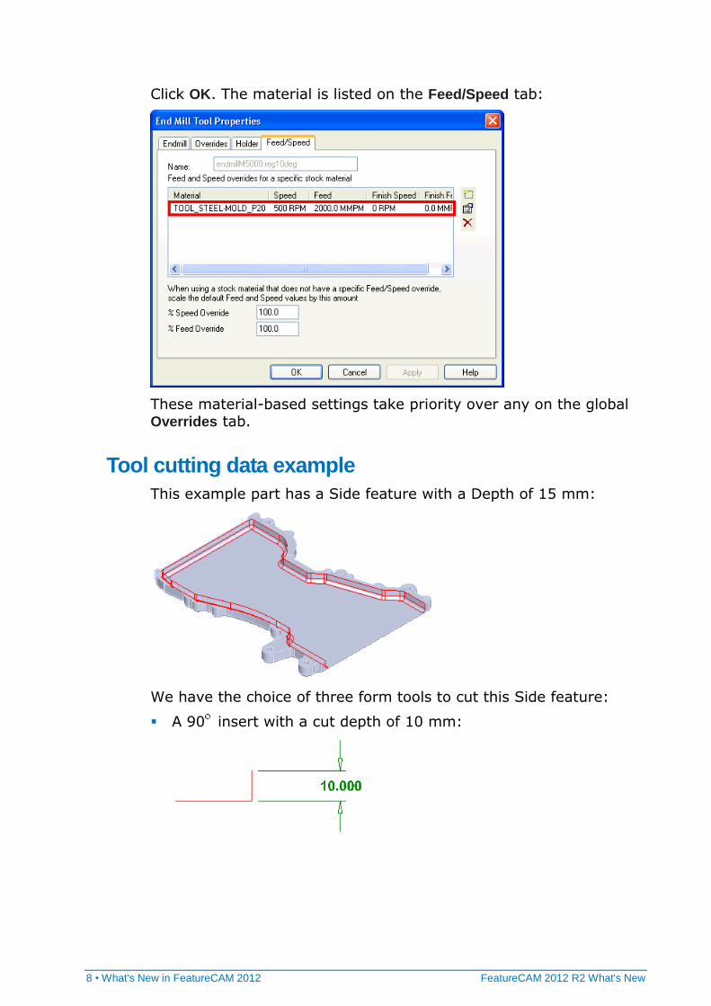
Click OK. The material is listed on the Feed/Speed tab:
These material-based settings take priority over any on the global Overrides tab.
Tool cutting data example
This example part has a Side feature with a Depth of 15 mm:
We have the choice of three form tools to cut this Side feature:
A 90 insert with a cut depth of 10 mm:
FeatureCAM 2012 R2 What's New What's New in FeatureCAM 2012 • 9
A 45 insert with a cut depth of 6.5 mm:
A 10 insert with a cut depth of 2 mm:
Each of these tools has a different feed rate associated with it as well as a different cut depth.
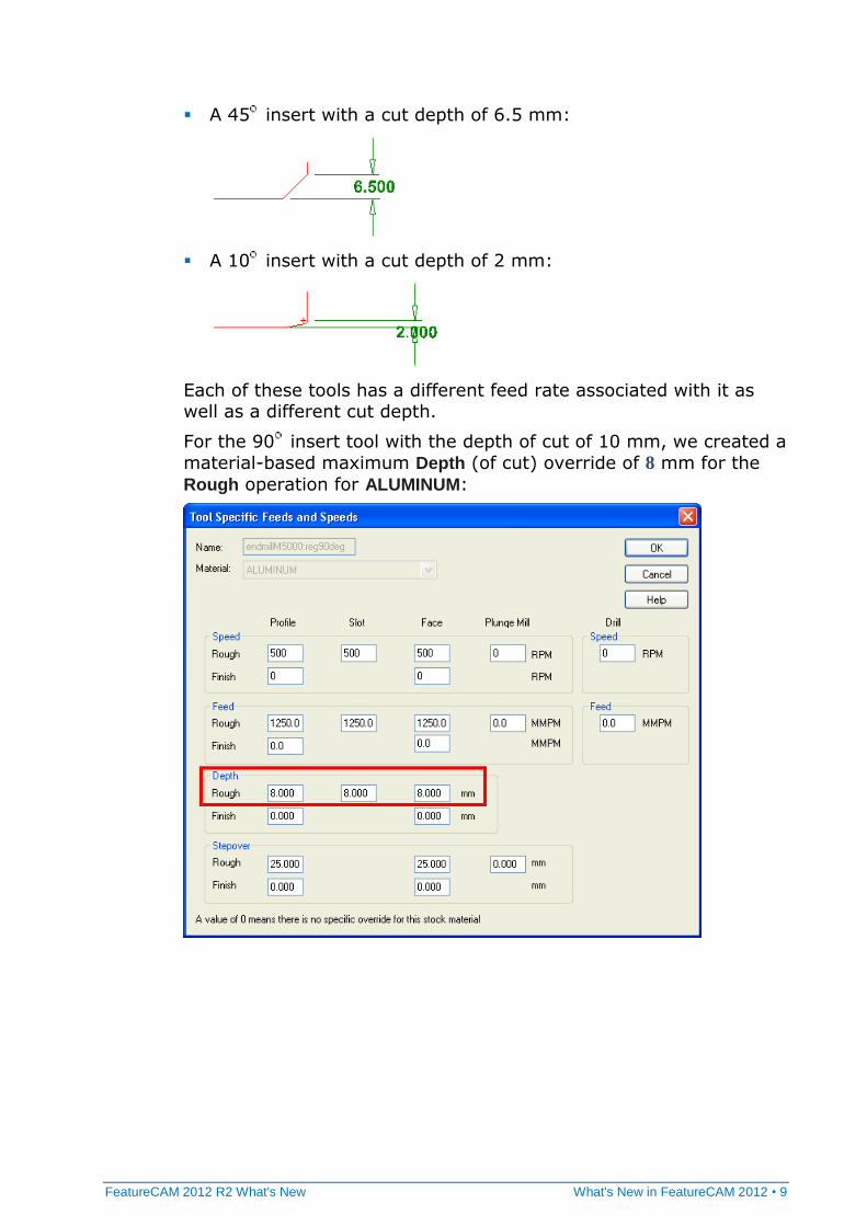
For the 90 insert tool with the depth of cut of 10 mm, we created a
material-based maximum Depth (of cut) override of 8 mm for the
Rough operation for ALUMINUM:
10 • What's New in FeatureCAM 2012 FeatureCAM 2012 R2 What's New
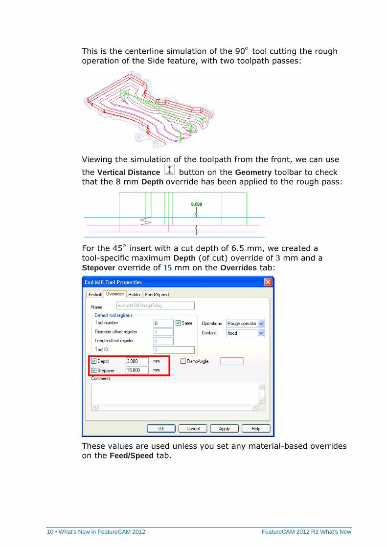
This is the centerline simulation of the 90 tool cutting the rough
operation of the Side feature, with two toolpath passes:
Viewing the simulation of the toolpath from the front, we can use
the Vertical Distance button on the Geometry toolbar to check that the 8 mm Depth override has been applied to the rough pass:
For the 45 insert with a cut depth of 6.5 mm, we created a
tool-specific maximum Depth (of cut) override of 3 mm and a
Stepover override of 15 mm on the Overrides tab:
These values are used unless you set any material-based overrides on the Feed/Speed tab.
FeatureCAM 2012 R2 What's New What's New in FeatureCAM 2012 • 11
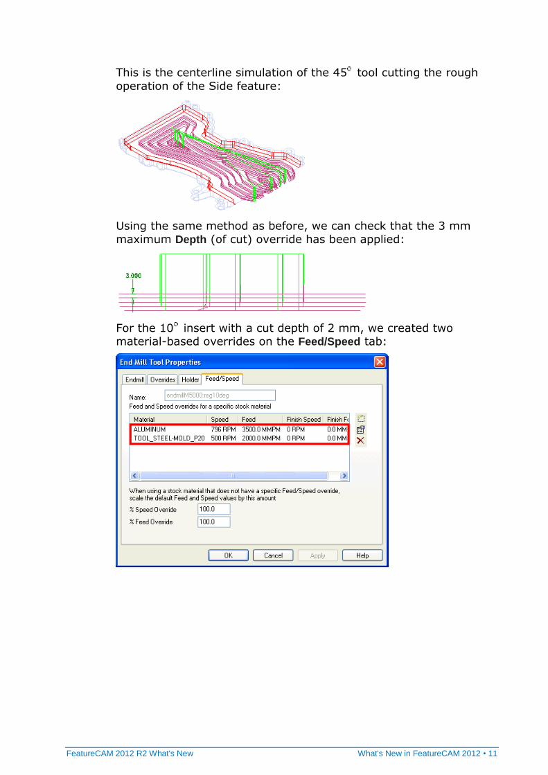
This is the centerline simulation of the 45 tool cutting the rough
operation of the Side feature:
Using the same method as before, we can check that the 3 mm maximum Depth (of cut) override has been applied:
For the 10 insert with a cut depth of 2 mm, we created two material-based overrides on the Feed/Speed tab:
12 • What's New in FeatureCAM 2012 FeatureCAM 2012 R2 What's New
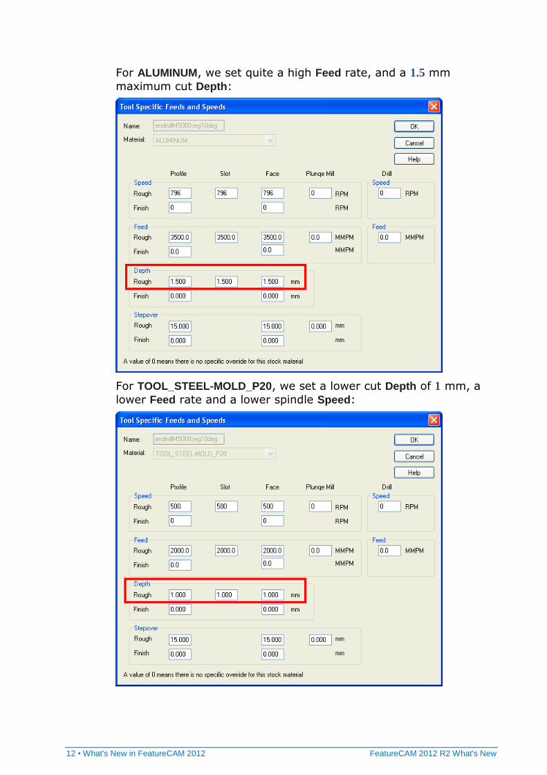
For ALUMINUM, we set quite a high Feed rate, and a 1.5 mm
maximum cut Depth:
For TOOL_STEEL-MOLD_P20, we set a lower cut Depth of 1 mm, a
lower Feed rate and a lower spindle Speed:
FeatureCAM 2012 R2 What's New What's New in FeatureCAM 2012 • 13
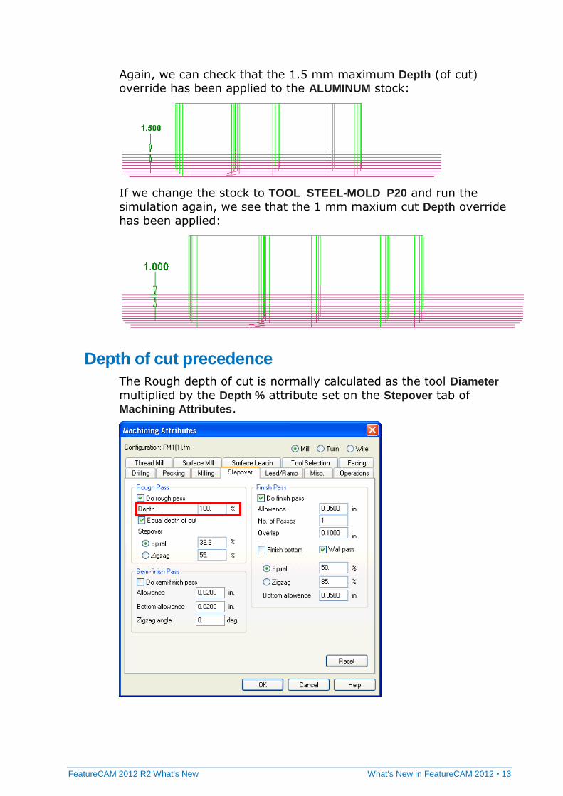
Again, we can check that the 1.5 mm maximum Depth (of cut)
override has been applied to the ALUMINUM stock:
If we change the stock to TOOL_STEEL-MOLD_P20 and run the
simulation again, we see that the 1 mm maxium cut Depth override
has been applied:
Depth of cut precedence
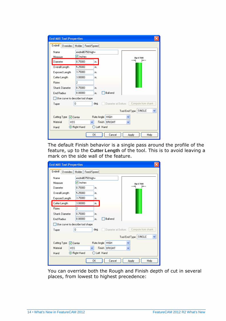
The Rough depth of cut is normally calculated as the tool Diameter
multiplied by the Depth % attribute set on the Stepover tab of Machining Attributes.
14 • What's New in FeatureCAM 2012 FeatureCAM 2012 R2 What's New
The default Finish behavior is a single pass around the profile of the feature, up to the Cutter Length of the tool. This is to avoid leaving a
mark on the side wall of the feature.
You can override both the Rough and Finish depth of cut in several places, from lowest to highest precedence:
FeatureCAM 2012 R2 What's New What's New in FeatureCAM 2012 • 15
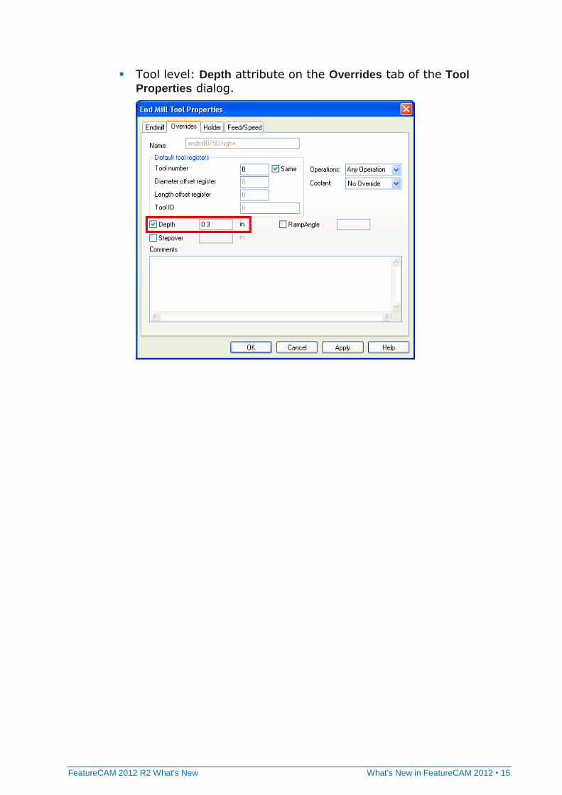
Tool level: Depth attribute on the Overrides tab of the Tool
Properties dialog.
16 • What's New in FeatureCAM 2012 FeatureCAM 2012 R2 What's New
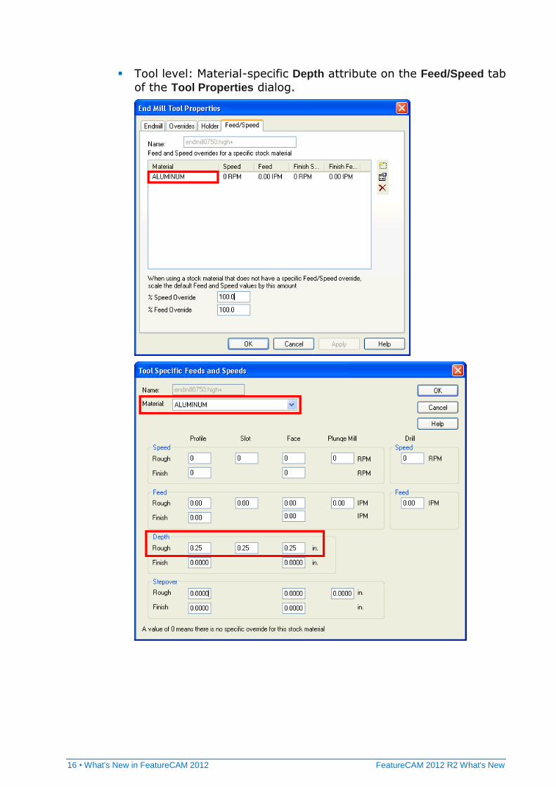
Tool level: Material-specific Depth attribute on the Feed/Speed tab
of the Tool Properties dialog.
FeatureCAM 2012 R2 What's New What's New in FeatureCAM 2012 • 17
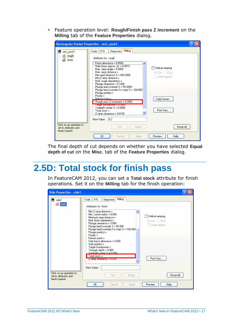
Feature operation level: Rough/Finish pass Z increment on the
Milling tab of the Feature Properties dialog.
The final depth of cut depends on whether you have selected Equal
depth of cut on the Misc. tab of the Feature Properties dialog.
2.5D: Total stock for finish pass In FeatureCAM 2012, you can set a Total stock attribute for finish
operations. Set it on the Milling tab for the finish operation:
18 • What's New in FeatureCAM 2012 FeatureCAM 2012 R2 What's New
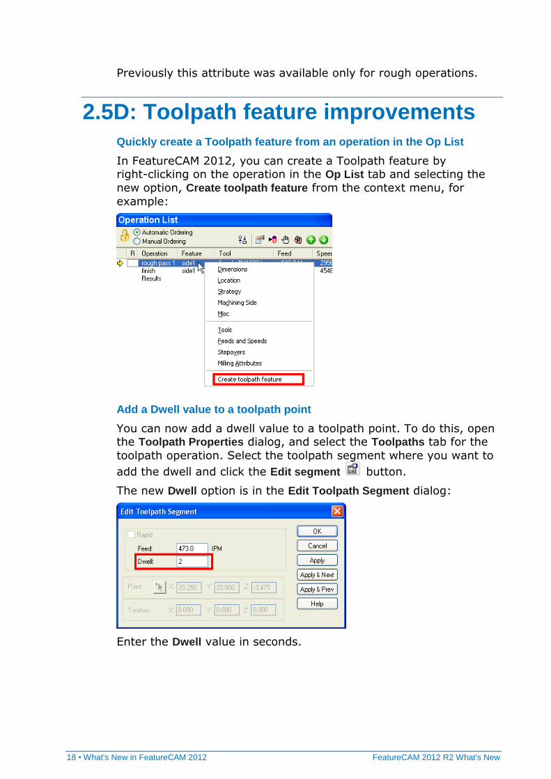
Previously this attribute was available only for rough operations.
2.5D: Toolpath feature improvements
Quickly create a Toolpath feature from an operation in the Op List
In FeatureCAM 2012, you can create a Toolpath feature by right-clicking on the operation in the Op List tab and selecting the
new option, Create toolpath feature from the context menu, for
example:
Add a Dwell value to a toolpath point
You can now add a dwell value to a toolpath point. To do this, open the Toolpath Properties dialog, and select the Toolpaths tab for the
toolpath operation. Select the toolpath segment where you want to
add the dwell and click the Edit segment button.
The new Dwell option is in the Edit Toolpath Segment dialog:
Enter the Dwell value in seconds.
FeatureCAM 2012 R2 What's New What's New in FeatureCAM 2012 • 19
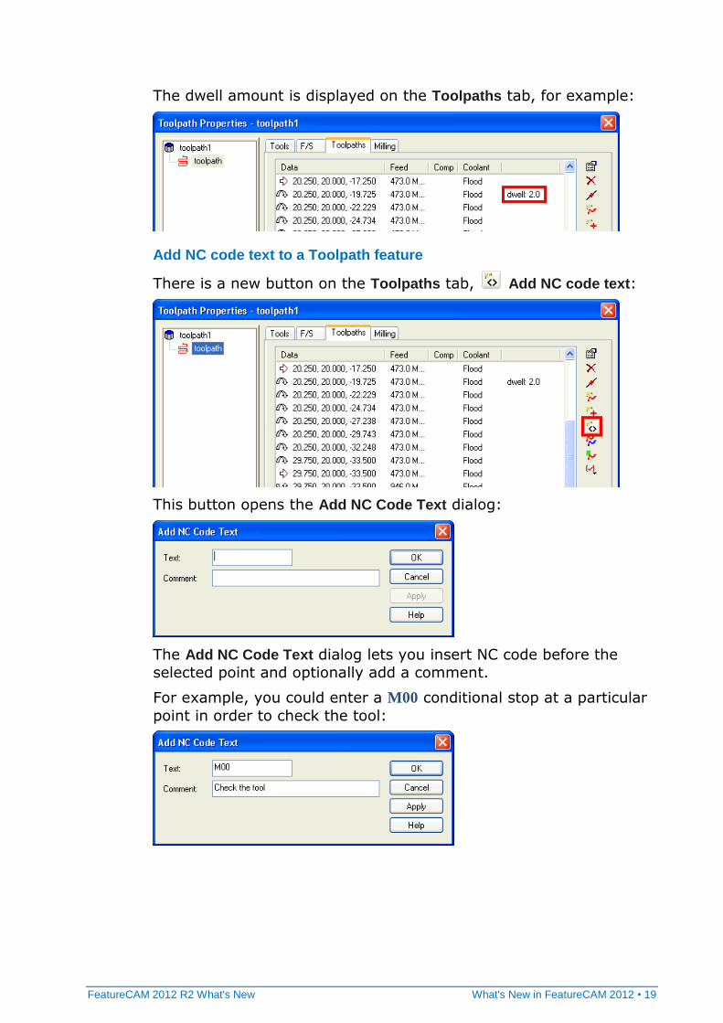
The dwell amount is displayed on the Toolpaths tab, for example:
Add NC code text to a Toolpath feature
There is a new button on the Toolpaths tab, Add NC code text:
This button opens the Add NC Code Text dialog:
The Add NC Code Text dialog lets you insert NC code before the
selected point and optionally add a comment.
For example, you could enter a M00 conditional stop at a particular
point in order to check the tool:
20 • What's New in FeatureCAM 2012 FeatureCAM 2012 R2 What's New
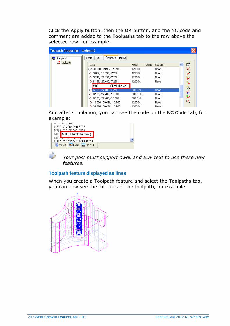
Click the Apply button, then the OK button, and the NC code and
comment are added to the Toolpaths tab to the row above the
selected row, for example:
And after simulation, you can see the code on the NC Code tab, for
example:
Your post must support dwell and EDF text to use these new
features.
Toolpath feature displayed as lines
When you create a Toolpath feature and select the Toolpaths tab,
you can now see the full lines of the toolpath, for example:
FeatureCAM 2012 R2 What's New What's New in FeatureCAM 2012 • 21
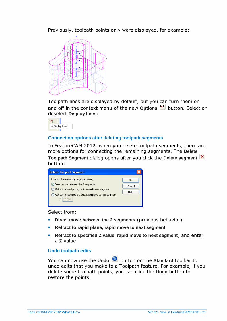
Previously, toolpath points only were displayed, for example:
Toolpath lines are displayed by default, but you can turn them on
and off in the context menu of the new Options button. Select or deselect Display lines:
Connection options after deleting toolpath segments
In FeatureCAM 2012, when you delete toolpath segments, there are more options for connecting the remaining segments. The Delete
Toolpath Segment dialog opens after you click the Delete segment
button:
Select from:
Direct move between the 2 segments (previous behavior)
Retract to rapid plane, rapid move to next segment
Retract to specified Z value, rapid move to next segment, and enter
a Z value
Undo toolpath edits
You can now use the Undo button on the Standard toolbar to
undo edits that you make to a Toolpath feature. For example, if you delete some toolpath points, you can click the Undo button to
restore the points.
22 • What's New in FeatureCAM 2012 FeatureCAM 2012 R2 What's New
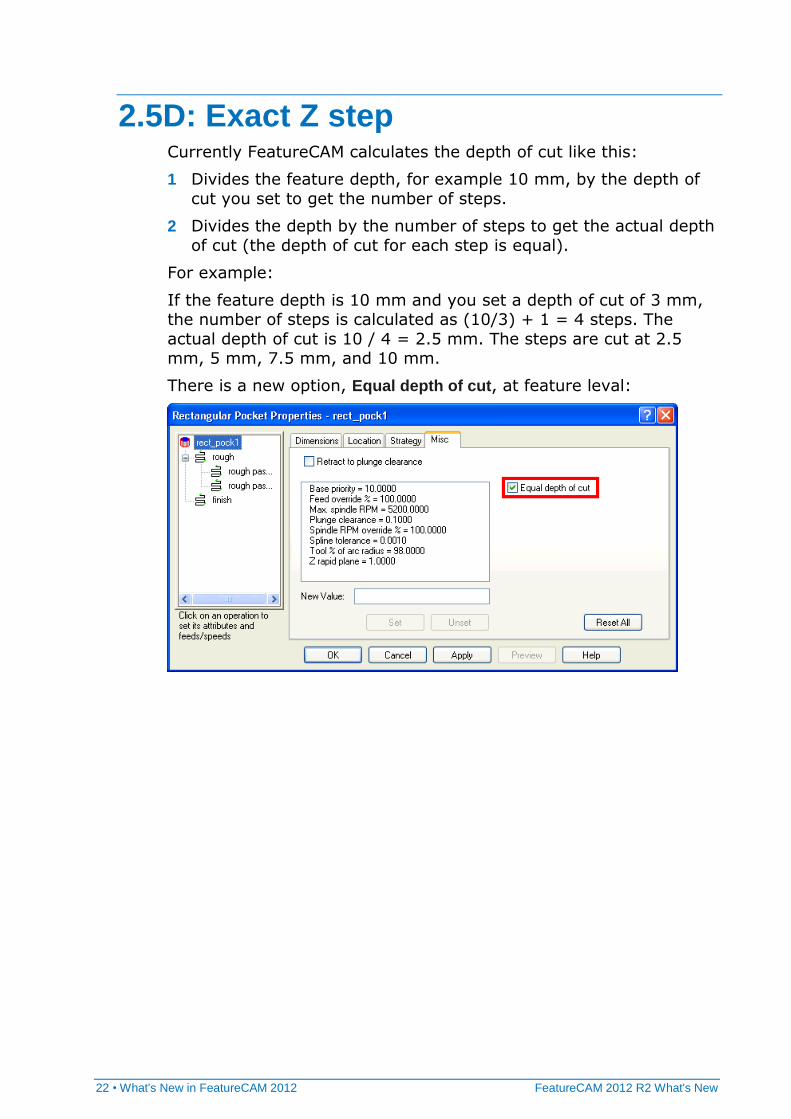
2.5D: Exact Z step Currently FeatureCAM calculates the depth of cut like this:
1 Divides the feature depth, for example 10 mm, by the depth of
cut you set to get the number of steps.
2 Divides the depth by the number of steps to get the actual depth
of cut (the depth of cut for each step is equal).
For example:
If the feature depth is 10 mm and you set a depth of cut of 3 mm, the number of steps is calculated as (10/3) + 1 = 4 steps. The
actual depth of cut is 10 / 4 = 2.5 mm. The steps are cut at 2.5 mm, 5 mm, 7.5 mm, and 10 mm.
There is a new option, Equal depth of cut, at feature leval:
FeatureCAM 2012 R2 What's New What's New in FeatureCAM 2012 • 23
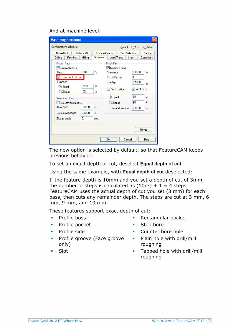
And at machine level:
The new option is selected by default, so that FeatureCAM keeps previous behavior.
To set an exact depth of cut, deselect Equal depth of cut.
Using the same example, with Equal depth of cut deselected:
If the feature depth is 10mm and you set a depth of cut of 3mm,
the number of steps is calculated as (10/3) + 1 = 4 steps. FeatureCAM uses the actual depth of cut you set (3 mm) for each
pass, then cuts any remainder depth. The steps are cut at 3 mm, 6 mm, 9 mm, and 10 mm.
These features support exact depth of cut:
Profile boss
Profile pocket
Profile side
Profile groove (Face groove
only)
Slot
Rectangular pocket
Step bore
Counter bore hole
Plain hole with drill/mill
roughing
Tapped hole with drill/mill
roughing
24 • What's New in FeatureCAM 2012 FeatureCAM 2012 R2 What's New
2.5D: Back Bore holes In FeatureCAM 2012, you can create a back bore cycle (such as a
Fanuc G87). The Back Bore hole type lets you machine back bore
holes using a single Setup.
You must use a post processor that supports back bore holes.
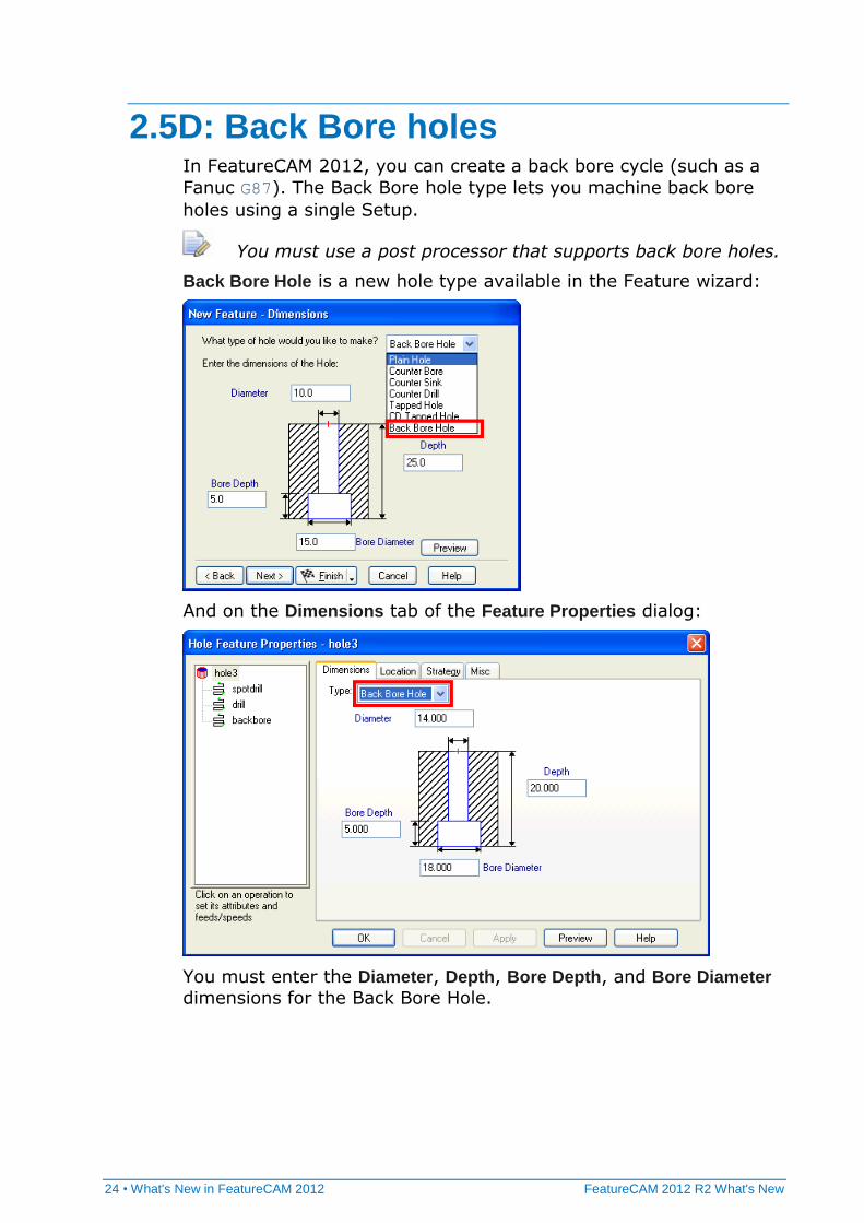
Back Bore Hole is a new hole type available in the Feature wizard:
And on the Dimensions tab of the Feature Properties dialog:
You must enter the Diameter, Depth, Bore Depth, and Bore Diameter
dimensions for the Back Bore Hole.
FeatureCAM 2012 R2 What's New What's New in FeatureCAM 2012 • 25
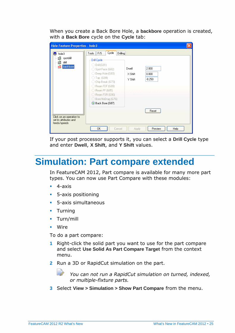
When you create a Back Bore Hole, a backbore operation is created,
with a Back Bore cycle on the Cycle tab:
If your post processor supports it, you can select a Drill Cycle type
and enter Dwell, X Shift, and Y Shift values.
Simulation: Part compare extended In FeatureCAM 2012, Part compare is available for many more part
types. You can now use Part Compare with these modules:
4-axis
5-axis positioning
5-axis simultaneous
Turning
Turn/mill
Wire
To do a part compare:
1 Right-click the solid part you want to use for the part compare and select Use Solid As Part Compare Target from the context
menu.
2 Run a 3D or RapidCut simulation on the part.
You can not run a RapidCut simulation on turned, indexed,
or multiple-fixture parts.
3 Select View > Simulation > Show Part Compare from the menu.
26 • What's New in FeatureCAM 2012 FeatureCAM 2012 R2 What's New
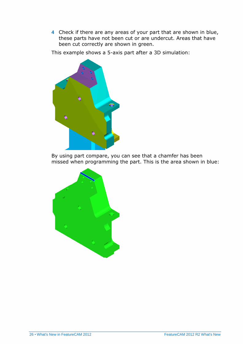
4 Check if there are any areas of your part that are shown in blue,
these parts have not been cut or are undercut. Areas that have been cut correctly are shown in green.
This example shows a 5-axis part after a 3D simulation:
By using part compare, you can see that a chamfer has been
missed when programming the part. This is the area shown in blue:
FeatureCAM 2012 R2 What's New What's New in FeatureCAM 2012 • 27
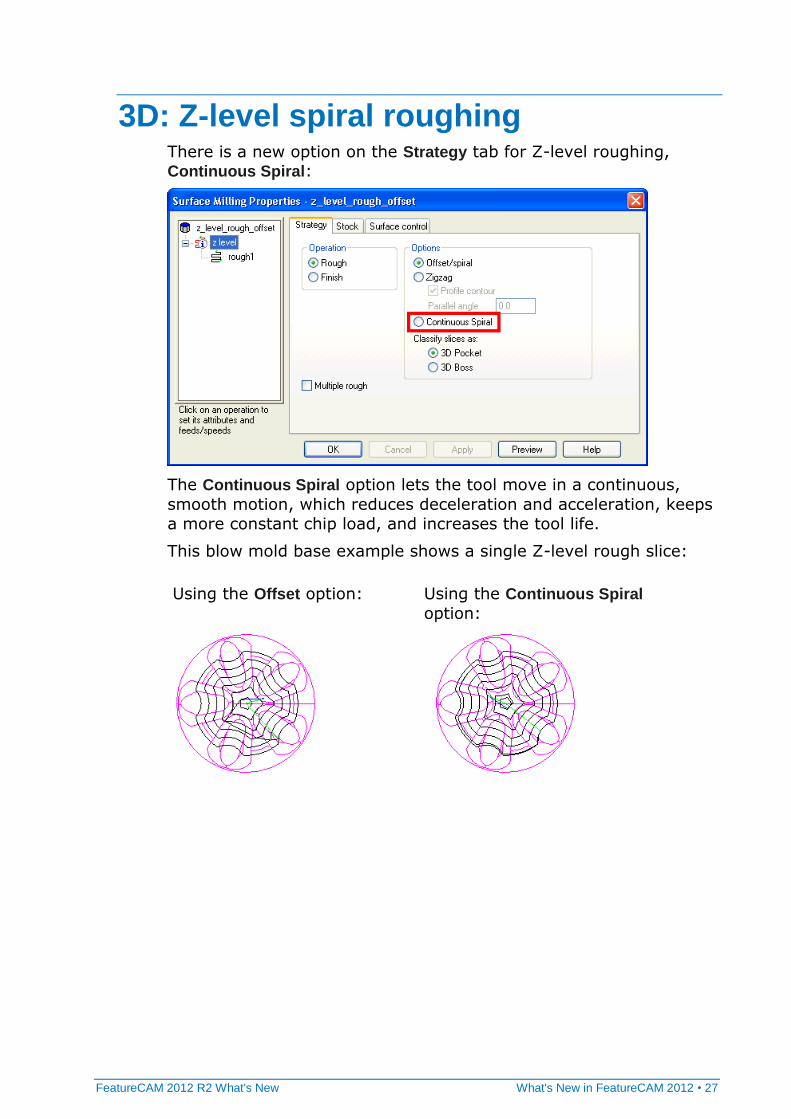
3D: Z-level spiral roughing There is a new option on the Strategy tab for Z-level roughing, Continuous Spiral:
The Continuous Spiral option lets the tool move in a continuous,
smooth motion, which reduces deceleration and acceleration, keeps
a more constant chip load, and increases the tool life.
This blow mold base example shows a single Z-level rough slice:
Using the Offset option: Using the Continuous Spiral
option:
28 • What's New in FeatureCAM 2012 FeatureCAM 2012 R2 What's New
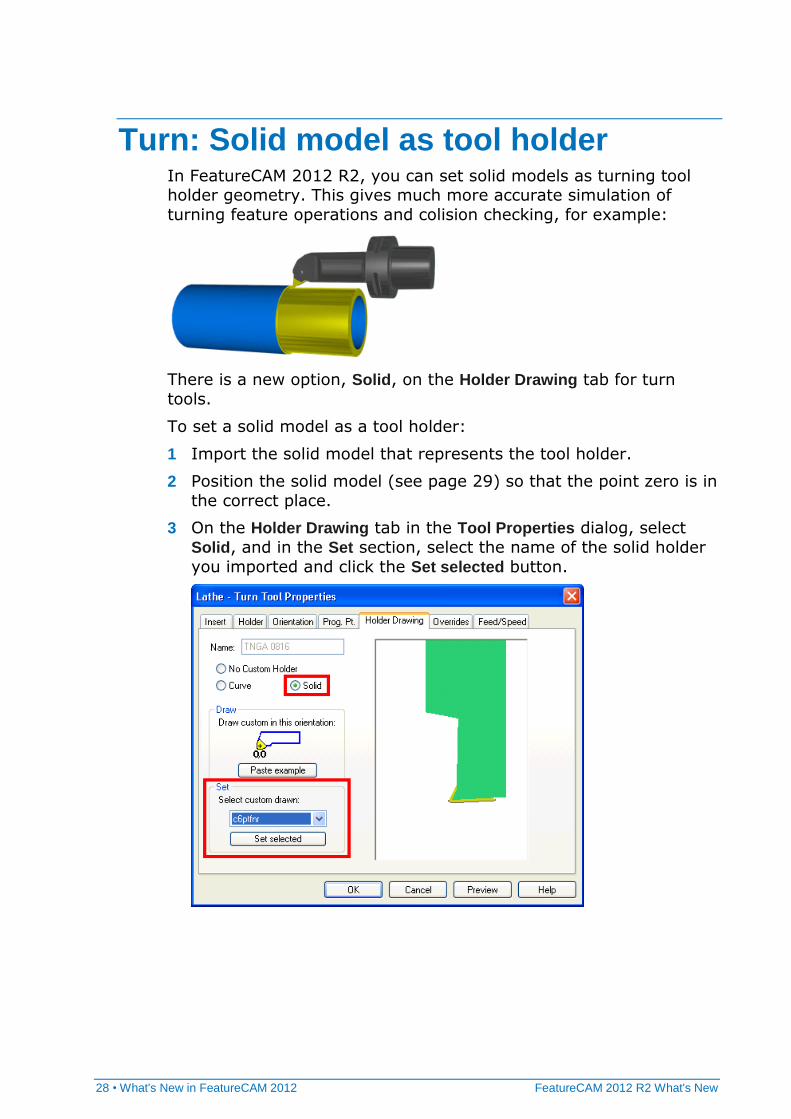
Turn: Solid model as tool holder In FeatureCAM 2012 R2, you can set solid models as turning tool holder geometry. This gives much more accurate simulation of
turning feature operations and colision checking, for example:
There is a new option, Solid, on the Holder Drawing tab for turn
tools.
To set a solid model as a tool holder:
1 Import the solid model that represents the tool holder.
2 Position the solid model (see page 29) so that the point zero is in
the correct place.
3 On the Holder Drawing tab in the Tool Properties dialog, select
Solid, and in the Set section, select the name of the solid holder
you imported and click the Set selected button.
FeatureCAM 2012 R2 What's New What's New in FeatureCAM 2012 • 29
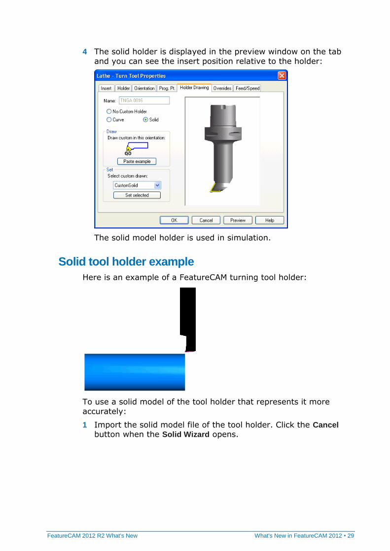
4 The solid holder is displayed in the preview window on the tab
and you can see the insert position relative to the holder:
The solid model holder is used in simulation.
Solid tool holder example
Here is an example of a FeatureCAM turning tool holder:
To use a solid model of the tool holder that represents it more
accurately:
1 Import the solid model file of the tool holder. Click the Cancel button when the Solid Wizard opens.
30 • What's New in FeatureCAM 2012 FeatureCAM 2012 R2 What's New
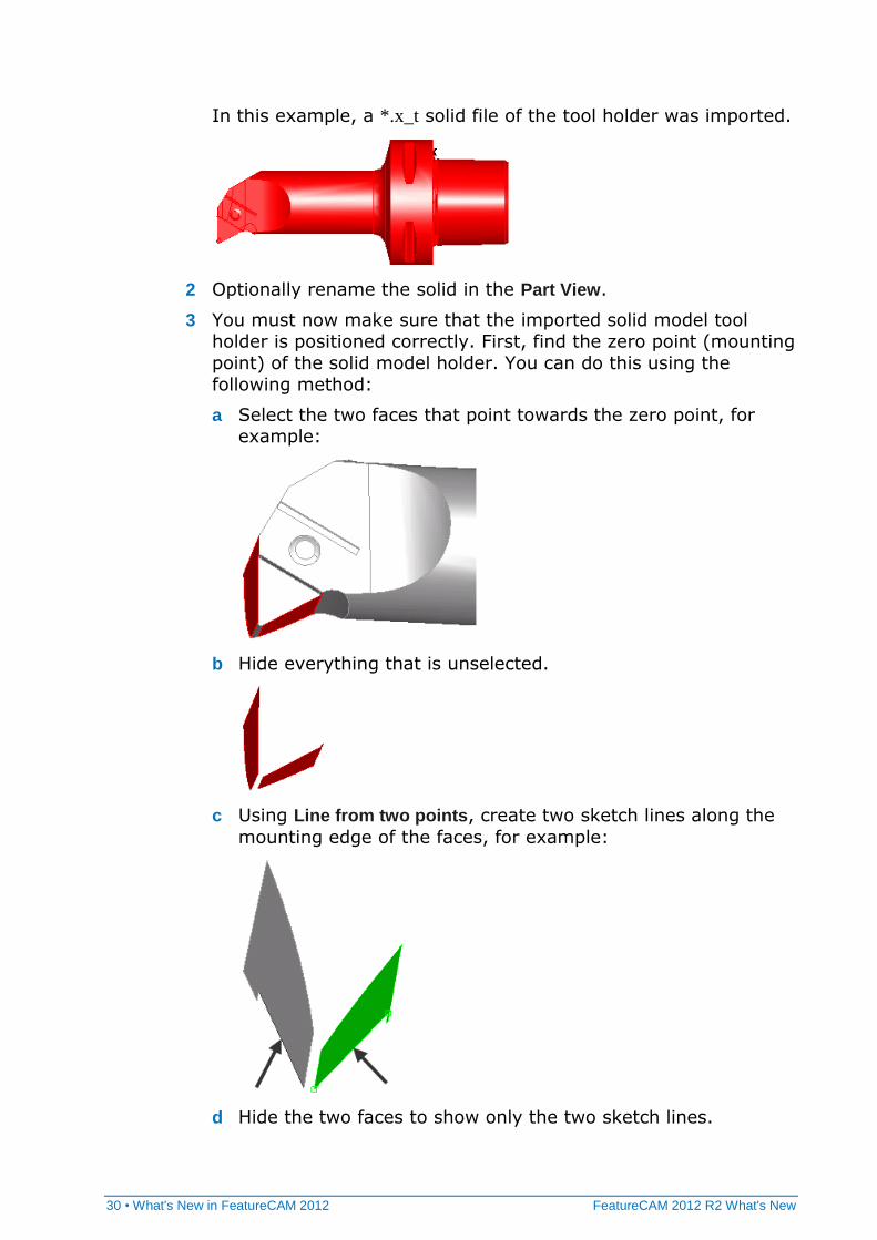
In this example, a *.x_t solid file of the tool holder was imported.
2 Optionally rename the solid in the Part View.
3 You must now make sure that the imported solid model tool holder is positioned correctly. First, find the zero point (mounting
point) of the solid model holder. You can do this using the following method:
a Select the two faces that point towards the zero point, for example:
b Hide everything that is unselected.
c Using Line from two points, create two sketch lines along the
mounting edge of the faces, for example:
d Hide the two faces to show only the two sketch lines.
FeatureCAM 2012 R2 What's New What's New in FeatureCAM 2012 • 31
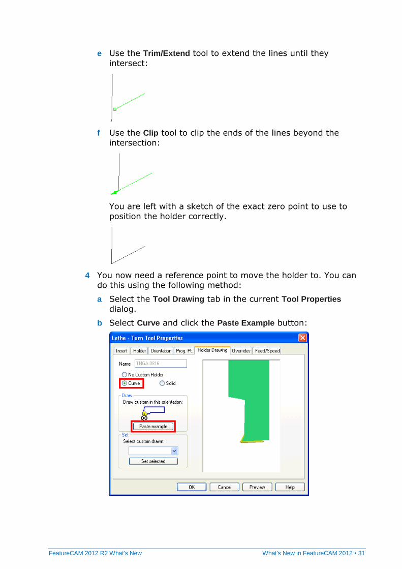
e Use the Trim/Extend tool to extend the lines until they
intersect:
f Use the Clip tool to clip the ends of the lines beyond the
intersection:
You are left with a sketch of the exact zero point to use to
position the holder correctly.
4 You now need a reference point to move the holder to. You can
do this using the following method:
a Select the Tool Drawing tab in the current Tool Properties
dialog.
b Select Curve and click the Paste Example button:
32 • What's New in FeatureCAM 2012 FeatureCAM 2012 R2 What's New
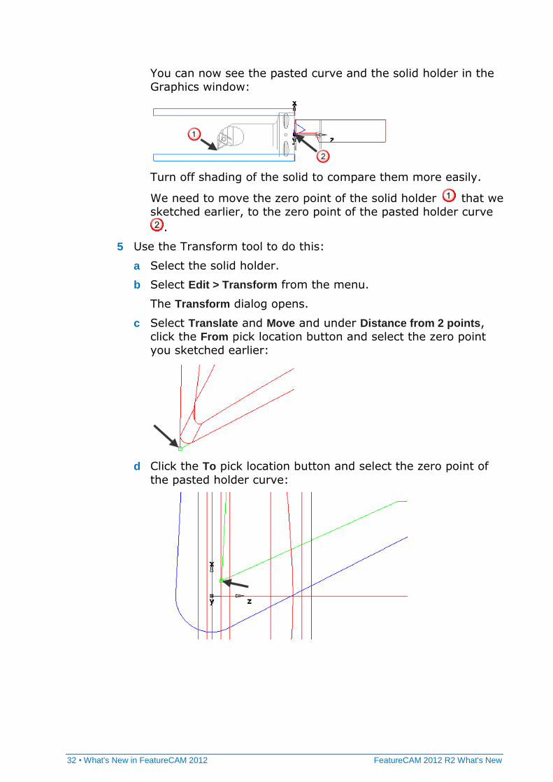
You can now see the pasted curve and the solid holder in the
Graphics window:
Turn off shading of the solid to compare them more easily.
We need to move the zero point of the solid holder that we
sketched earlier, to the zero point of the pasted holder curve
.
5 Use the Transform tool to do this:
a Select the solid holder.
b Select Edit > Transform from the menu.
The Transform dialog opens.
c Select Translate and Move and under Distance from 2 points,
click the From pick location button and select the zero point
you sketched earlier:
d Click the To pick location button and select the zero point of
the pasted holder curve:
FeatureCAM 2012 R2 What's New What's New in FeatureCAM 2012 • 33
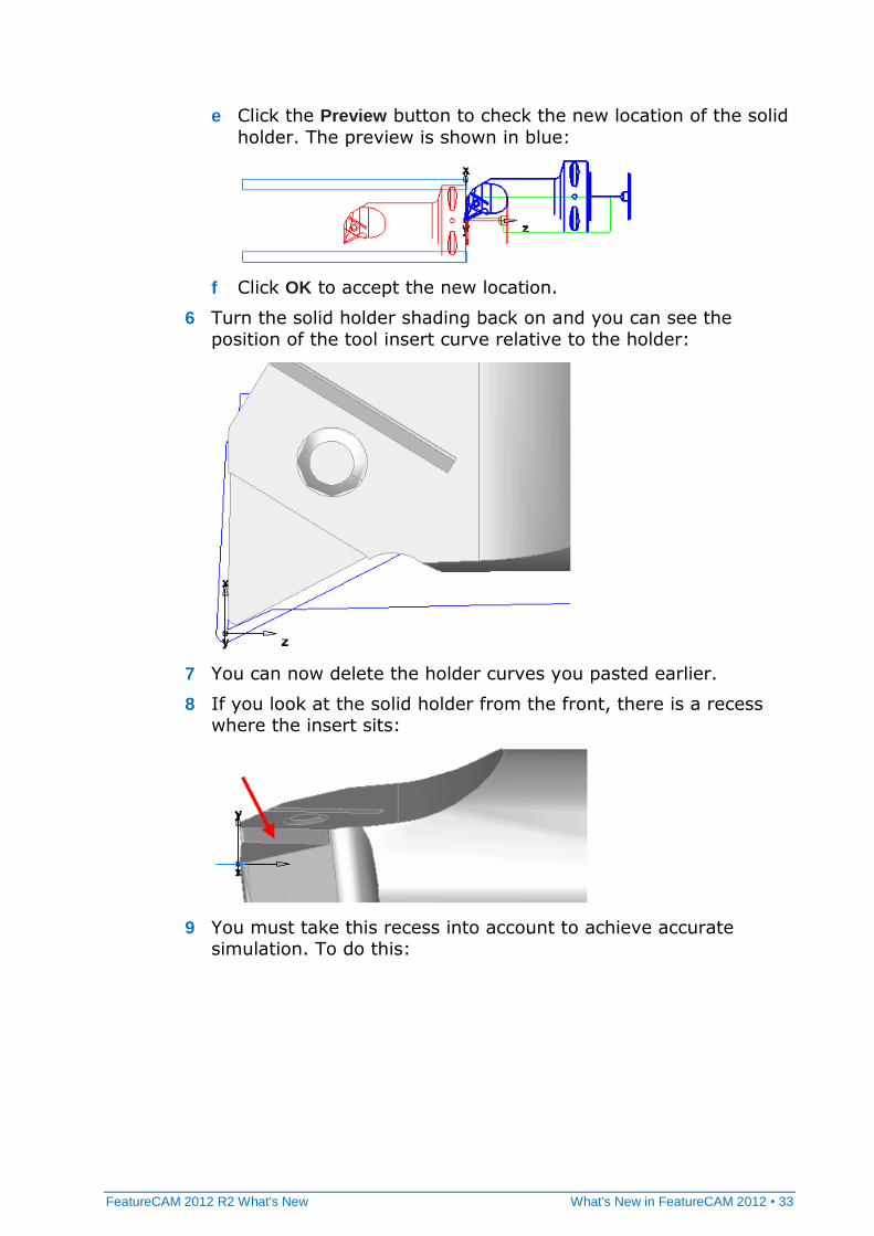
e Click the Preview button to check the new location of the solid
holder. The preview is shown in blue:
f Click OK to accept the new location.
6 Turn the solid holder shading back on and you can see the
position of the tool insert curve relative to the holder:
7 You can now delete the holder curves you pasted earlier.
8 If you look at the solid holder from the front, there is a recess where the insert sits:
9 You must take this recess into account to achieve accurate simulation. To do this:
34 • What's New in FeatureCAM 2012 FeatureCAM 2012 R2 What's New
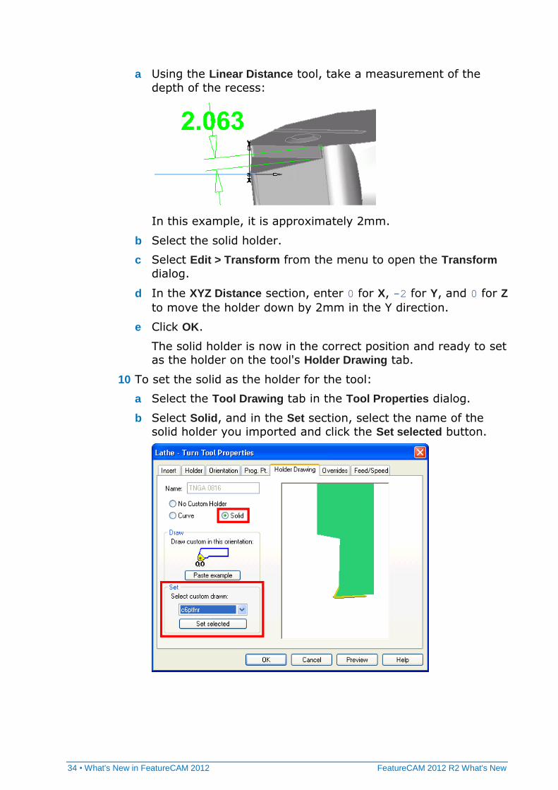
a Using the Linear Distance tool, take a measurement of the
depth of the recess:
In this example, it is approximately 2mm.
b Select the solid holder.
c Select Edit > Transform from the menu to open the Transform
dialog.
d In the XYZ Distance section, enter 0 for X, -2 for Y, and 0 for Z
to move the holder down by 2mm in the Y direction.
e Click OK.
The solid holder is now in the correct position and ready to set as the holder on the tool's Holder Drawing tab.
10 To set the solid as the holder for the tool:
a Select the Tool Drawing tab in the Tool Properties dialog.
b Select Solid, and in the Set section, select the name of the
solid holder you imported and click the Set selected button.
FeatureCAM 2012 R2 What's New What's New in FeatureCAM 2012 • 35
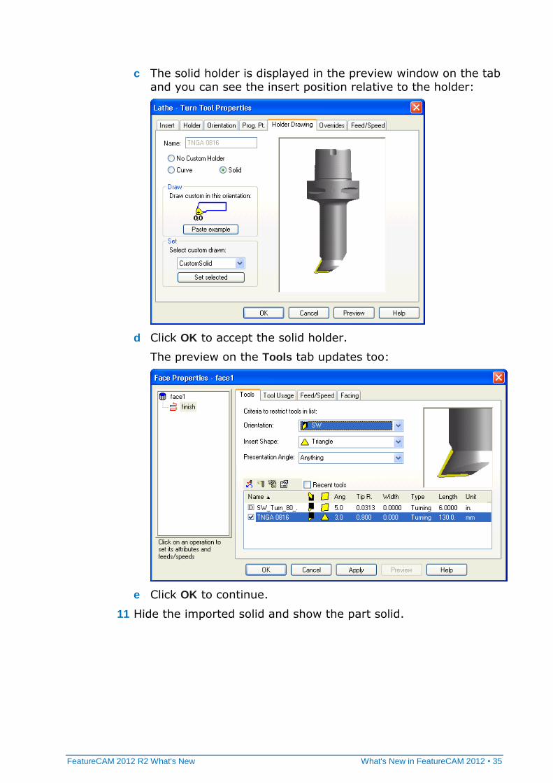
c The solid holder is displayed in the preview window on the tab
and you can see the insert position relative to the holder:
d Click OK to accept the solid holder.
The preview on the Tools tab updates too:
e Click OK to continue.
11 Hide the imported solid and show the part solid.
36 • What's New in FeatureCAM 2012 FeatureCAM 2012 R2 What's New
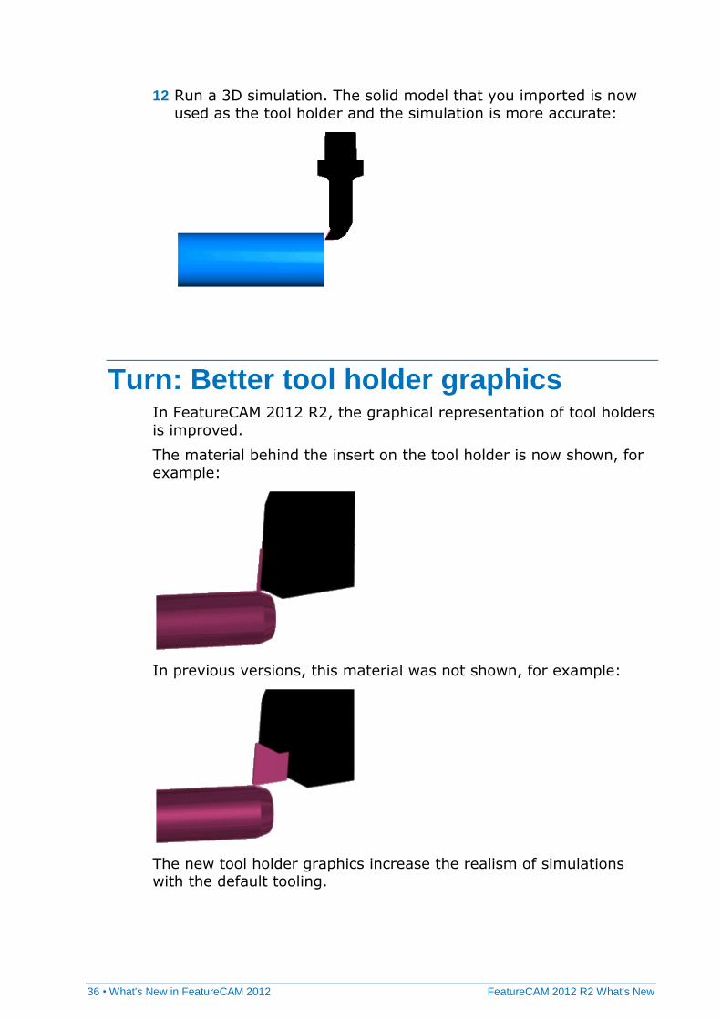
12 Run a 3D simulation. The solid model that you imported is now
used as the tool holder and the simulation is more accurate:
Turn: Better tool holder graphics In FeatureCAM 2012 R2, the graphical representation of tool holders
is improved.
The material behind the insert on the tool holder is now shown, for
example:
In previous versions, this material was not shown, for example:
The new tool holder graphics increase the realism of simulations with the default tooling.
FeatureCAM 2012 R2 What's New What's New in FeatureCAM 2012 • 37
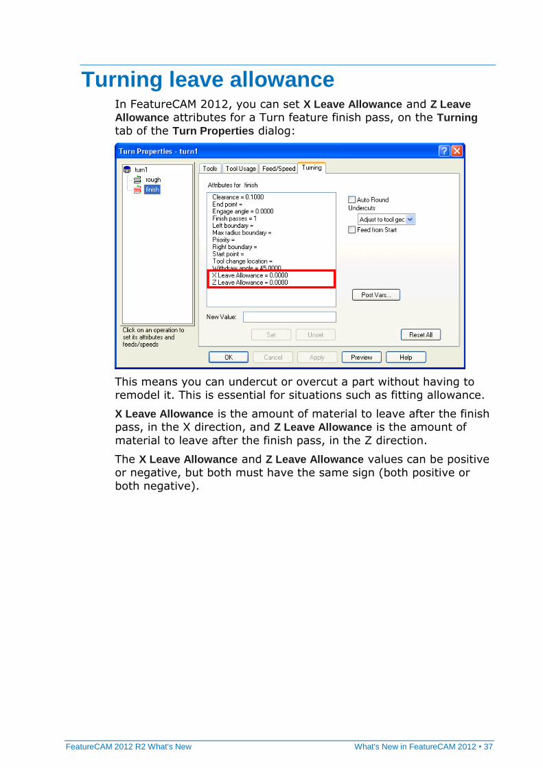
Turning leave allowance In FeatureCAM 2012, you can set X Leave Allowance and Z Leave
Allowance attributes for a Turn feature finish pass, on the Turning
tab of the Turn Properties dialog:
This means you can undercut or overcut a part without having to remodel it. This is essential for situations such as fitting allowance.
X Leave Allowance is the amount of material to leave after the finish pass, in the X direction, and Z Leave Allowance is the amount of
material to leave after the finish pass, in the Z direction.
The X Leave Allowance and Z Leave Allowance values can be positive
or negative, but both must have the same sign (both positive or
both negative).
38 • What's New in FeatureCAM 2012 R2 FeatureCAM 2012 R2 What's New
FeatureCAM 2012 R2 offers all of the original features of
FeatureCAM 2012, but with numerous improvements. The most significant improvements are detailed in the following topics.
Network database: Shared machining configurations
In FeatureCAM 2012 R2, you can share machining configurations across a network.
There are now three types of configuration:
File (f) - Configurations for files that are currently open.
Personal (p) - Configurations that are independent of a particular
file and are stored only on your PC.
Workgroup (w) - Configurations that are independent of a
particular file and are stored on a network for sharing with
colleagues.
What's New in FeatureCAM 2012 R2
FeatureCAM 2012 R2 What's New What's New in FeatureCAM 2012 R2 • 39
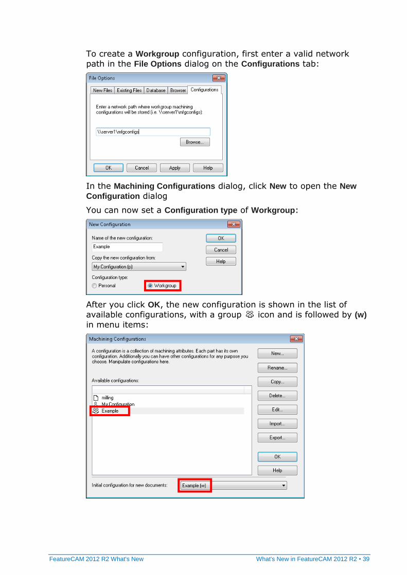
To create a Workgroup configuration, first enter a valid network
path in the File Options dialog on the Configurations tab:
In the Machining Configurations dialog, click New to open the New
Configuration dialog
You can now set a Configuration type of Workgroup:
After you click OK, the new configuration is shown in the list of
available configurations, with a group icon and is followed by (w)
in menu items:
40 • What's New in FeatureCAM 2012 R2 FeatureCAM 2012 R2 What's New
Import improvements FeatureCAM 2012 R2 can read Pro/E Family Tables, which are multiple configurations of a given part.
SolidEdge ST4 is now supported.
User interface: Copy and paste from PowerSHAPE
You can now copy and paste solids and surfaces from PowerSHAPE
into FeatureCAM. Surfaces, curves, lines, and arcs are supported.
You can also copy and paste solids from FeatureCAM into
PowerSHAPE.
2.5D: New technology (NT) toolpaths In FeatureCAM 2012 R2, there are three new roughing Stepover types:
NT Spiral - can use stepovers larger than 50%
NT Zigzag - uses an angle that is calculated automatically to cut
the longest toolpaths
NT Continuous Spiral - eliminates nearly all stepovers
The NT (new technology) toolpaths support Pocket, Rectangular
Pocket, and Boss features.
FeatureCAM 2012 R2 What's New What's New in FeatureCAM 2012 R2 • 41
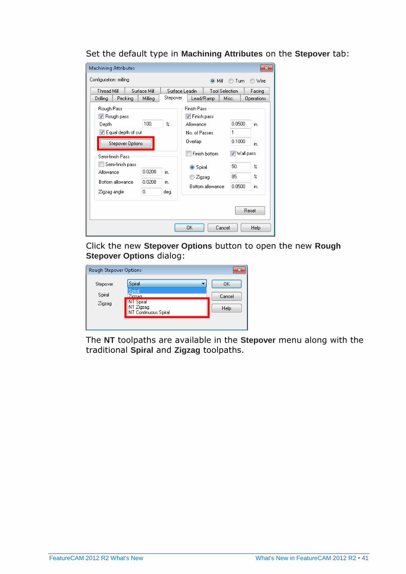
Set the default type in Machining Attributes on the Stepover tab:
Click the new Stepover Options button to open the new Rough
Stepover Options dialog:
The NT toolpaths are available in the Stepover menu along with the
traditional Spiral and Zigzag toolpaths.
42 • What's New in FeatureCAM 2012 R2 FeatureCAM 2012 R2 What's New
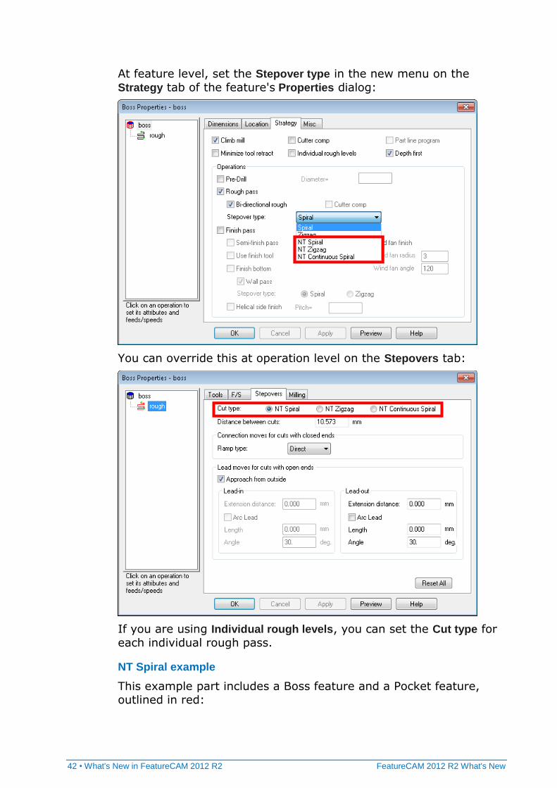
At feature level, set the Stepover type in the new menu on the
Strategy tab of the feature's Properties dialog:
You can override this at operation level on the Stepovers tab:
If you are using Individual rough levels, you can set the Cut type for
each individual rough pass.
NT Spiral example
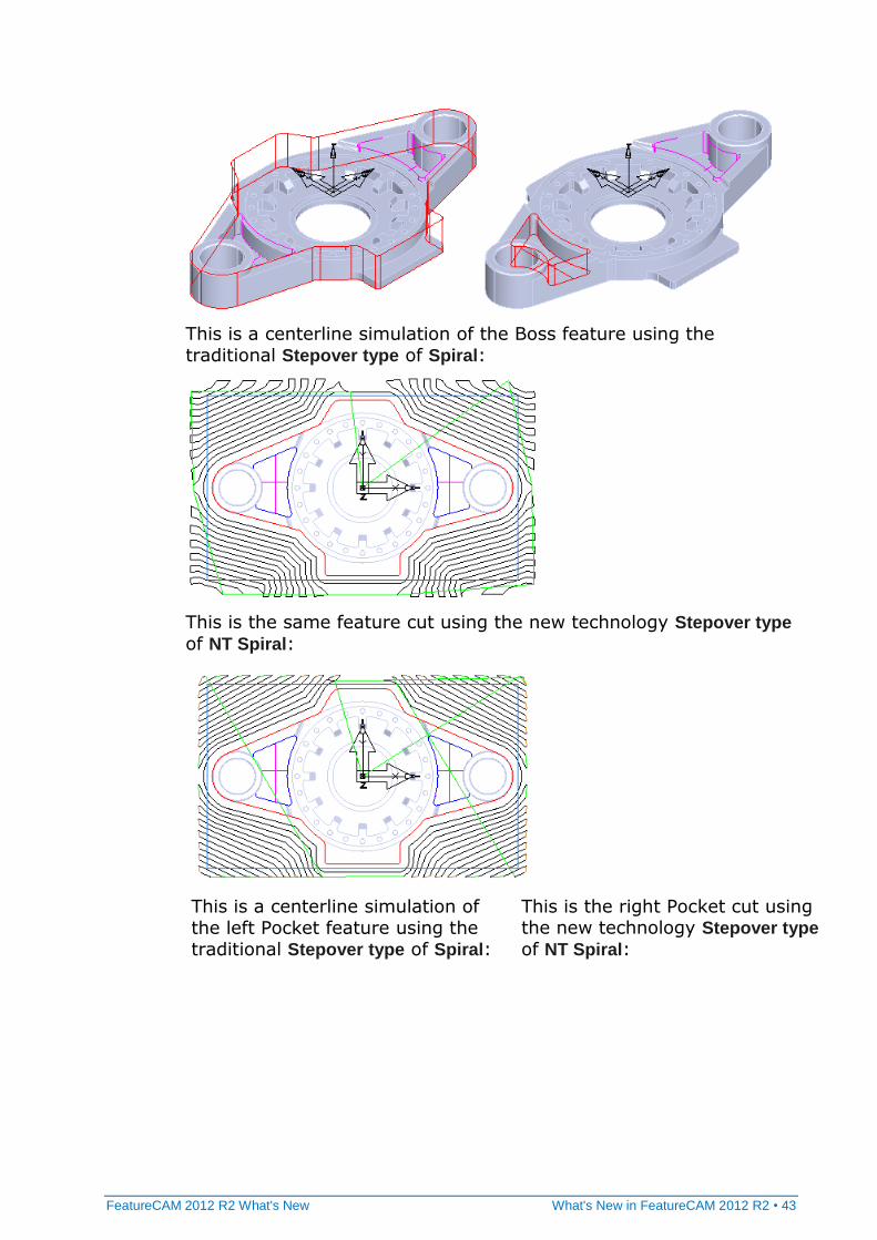
This example part includes a Boss feature and a Pocket feature, outlined in red:
FeatureCAM 2012 R2 What's New What's New in FeatureCAM 2012 R2 • 43
This is a centerline simulation of the Boss feature using the traditional Stepover type of Spiral:
This is the same feature cut using the new technology Stepover type
of NT Spiral:
This is a centerline simulation of the left Pocket feature using the traditional Stepover type of Spiral:
This is the right Pocket cut using the new technology Stepover type
of NT Spiral:
44 • What's New in FeatureCAM 2012 R2 FeatureCAM 2012 R2 What's New
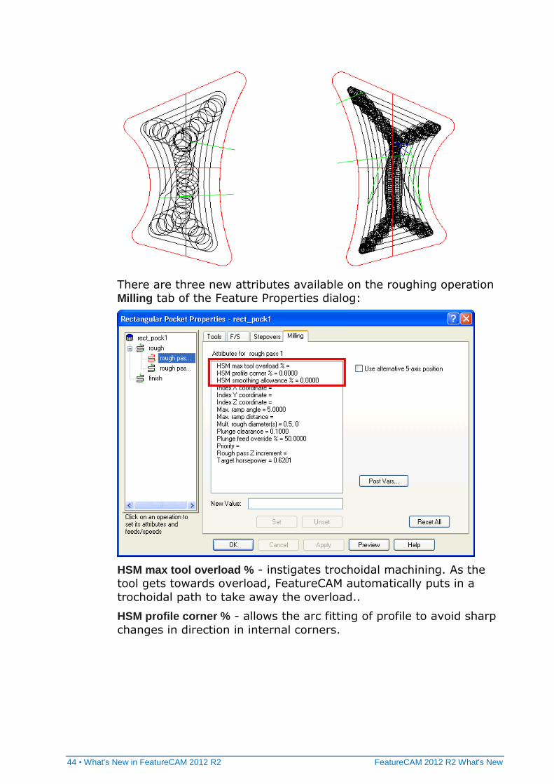
There are three new attributes available on the roughing operation Milling tab of the Feature Properties dialog:
HSM max tool overload % - instigates trochoidal machining. As the
tool gets towards overload, FeatureCAM automatically puts in a
trochoidal path to take away the overload..
HSM profile corner % - allows the arc fitting of profile to avoid sharp
changes in direction in internal corners.
FeatureCAM 2012 R2 What's New What's New in FeatureCAM 2012 R2 • 45
HSM smoothing allowance % - replaces the standard offset with a
smoother one that can achieve higher feed rates. For example, sharp corners are replaced with rounded corners. The percentage
defines the maximum deviation from the stepover. The maximum
percentage is 40% of stepover. So, if you have a 10 mm stepover
the maximum deviation from the original to the smoothed offset is 4 mm.
Differences between NT and traditional toolpaths
Pre-drill differences
There are some differences with how the Pre-drill operation works
with the NT toolpaths compared to the traditional toolpaths.
You can use a Pre-drill operation with the NT Zigzag toolpath. It is
not available for the traditional Zigzag toolpath.
With the NT toolpaths, zigzag ramping is automatically disabled when you use a Pre-drill operation. This is not supported for the
original Spiral toolpath and you must set the Max. ramp angle to 0
to disable zigzag ramping when using a Pre-drill operation.
The Pre-drill operation for the NT toolpaths includes the tops of
multi-height islands. This is not supported for the original
toolpaths.
The traditional Spiral toolpath supports manual plunge points for
the pre-drill locations using the Plunge point(s) attribute. The NT
toolpaths support only automatic locations.
Stepover differences
There are some differences in the attributes available for NT toolpaths on the feature Stepover tab:
There are two Ramp type options for the NT toolpaths:
Smooth - similar to the traditional toolpath option S-type
Direct - similar to the traditional toolpath option Line.
46 • What's New in FeatureCAM 2012 R2 FeatureCAM 2012 R2 What's New
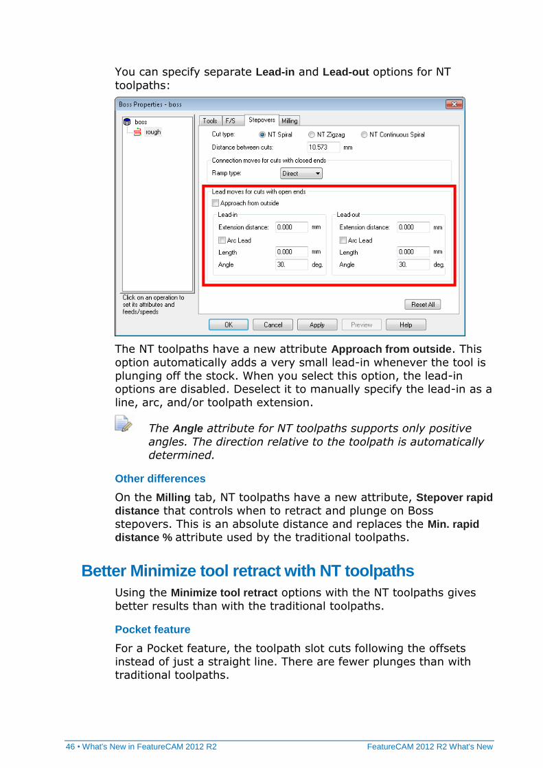
You can specify separate Lead-in and Lead-out options for NT
toolpaths:
The NT toolpaths have a new attribute Approach from outside. This
option automatically adds a very small lead-in whenever the tool is
plunging off the stock. When you select this option, the lead-in options are disabled. Deselect it to manually specify the lead-in as a
line, arc, and/or toolpath extension.
The Angle attribute for NT toolpaths supports only positive
angles. The direction relative to the toolpath is automatically
determined.
Other differences
On the Milling tab, NT toolpaths have a new attribute, Stepover rapid
distance that controls when to retract and plunge on Boss
stepovers. This is an absolute distance and replaces the Min. rapid
distance % attribute used by the traditional toolpaths.
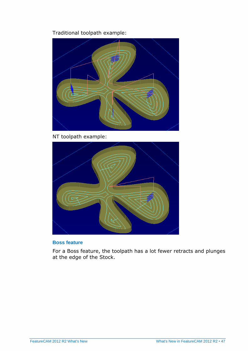
Better Minimize tool retract with NT toolpaths
Using the Minimize tool retract options with the NT toolpaths gives
better results than with the traditional toolpaths.
Pocket feature
For a Pocket feature, the toolpath slot cuts following the offsets
instead of just a straight line. There are fewer plunges than with
traditional toolpaths.
FeatureCAM 2012 R2 What's New What's New in FeatureCAM 2012 R2 • 47
Traditional toolpath example:
NT toolpath example:
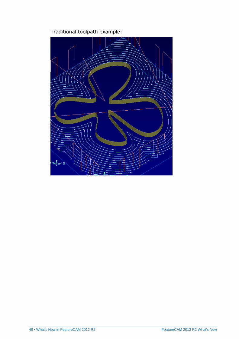
Boss feature
For a Boss feature, the toolpath has a lot fewer retracts and plunges
at the edge of the Stock.
48 • What's New in FeatureCAM 2012 R2 FeatureCAM 2012 R2 What's New
Traditional toolpath example:

FeatureCAM 2012 R2 What's New What's New in FeatureCAM 2012 R2 • 49
NT toolpath example:
50 • What's New in FeatureCAM 2012 R2 FeatureCAM 2012 R2 What's New
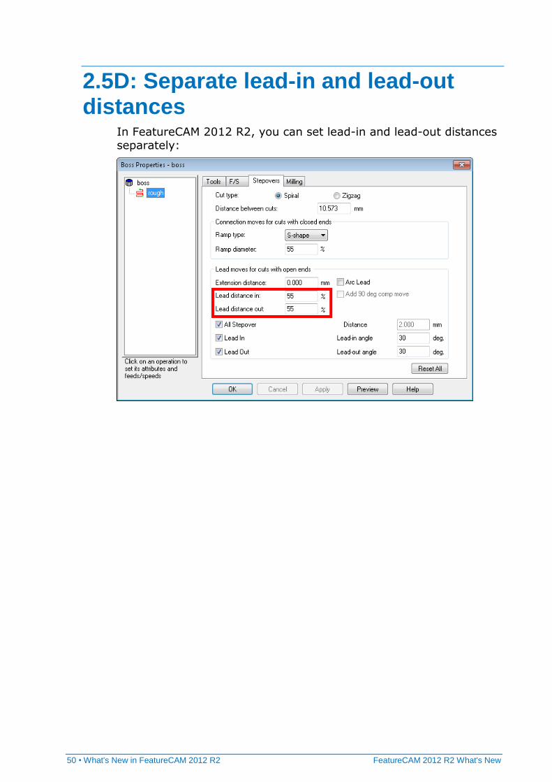
2.5D: Separate lead-in and lead-out distances
In FeatureCAM 2012 R2, you can set lead-in and lead-out distances separately:
FeatureCAM 2012 R2 What's New What's New in FeatureCAM 2012 R2 • 51
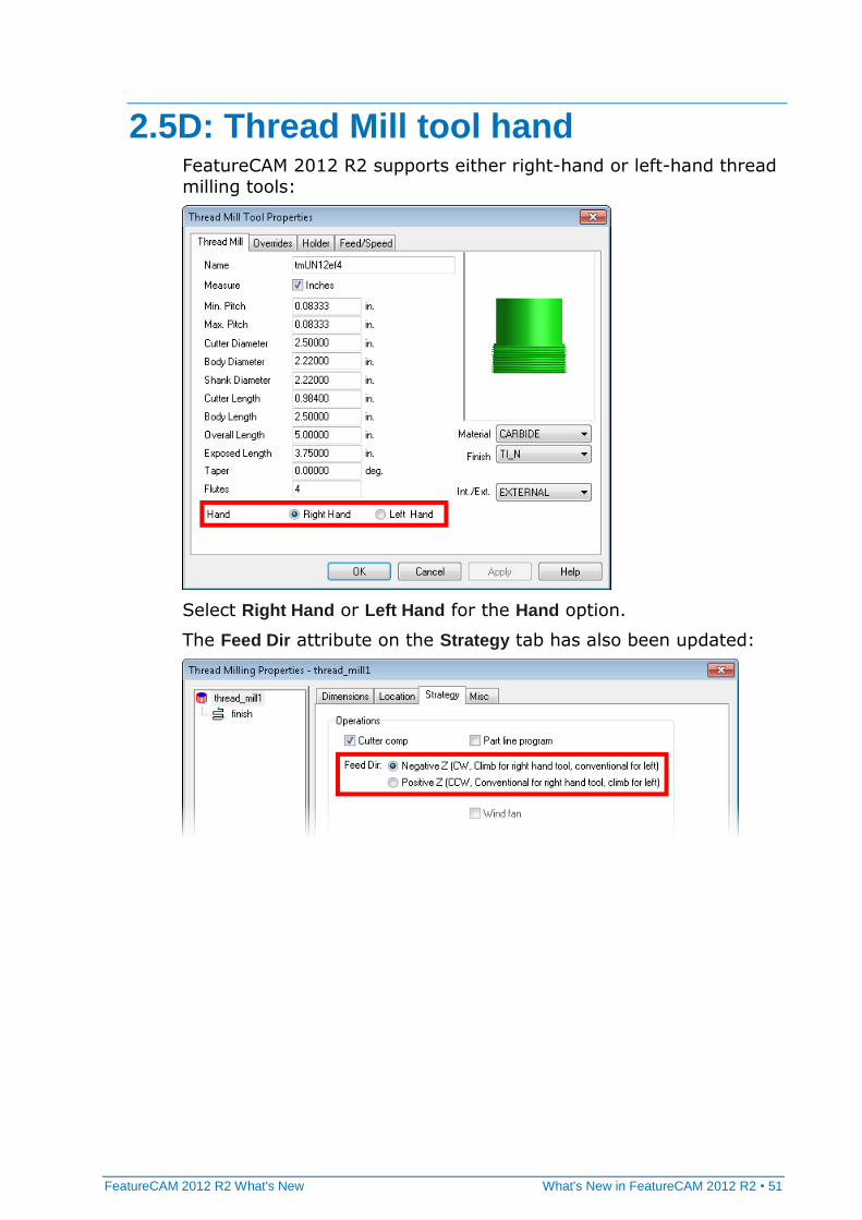
2.5D: Thread Mill tool hand FeatureCAM 2012 R2 supports either right-hand or left-hand thread milling tools:
Select Right Hand or Left Hand for the Hand option.
The Feed Dir attribute on the Strategy tab has also been updated:

52 • What's New in FeatureCAM 2012 R2 FeatureCAM 2012 R2 What's New
2.5D: Face Mill tools for Chamfers In FeatureCAM 2012 R2, you can use a chamfered Face Mill tool to cut a Chamfer feature. Face Mill tools are now available in the Tool
Group menu on the Tools tab:
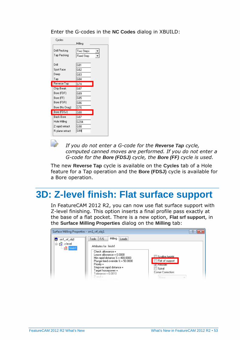
2.5D: Hole cycle G74 and G88 FeatureCAM now supports the hole cycles G74 (left-handed tapping) and G88 (boring cycle).
FeatureCAM 2012 R2 What's New What's New in FeatureCAM 2012 R2 • 53
Enter the G-codes in the NC Codes dialog in XBUILD:
If you do not enter a G-code for the Reverse Tap cycle,
computed canned moves are performed. If you do not enter a G-code for the Bore (FDSJ) cycle, the Bore (FF) cycle is used.
The new Reverse Tap cycle is available on the Cycles tab of a Hole
feature for a Tap operation and the Bore (FDSJ) cycle is available for
a Bore operation.
3D: Z-level finish: Flat surface support In FeatureCAM 2012 R2, you can now use flat surface support with
Z-level finishing. This option inserts a final profile pass exactly at the base of a flat pocket. There is a new option, Flat srf support, in
the Surface Milling Properties dialog on the Milling tab:
54 • What's New in FeatureCAM 2012 R2 FeatureCAM 2012 R2 What's New
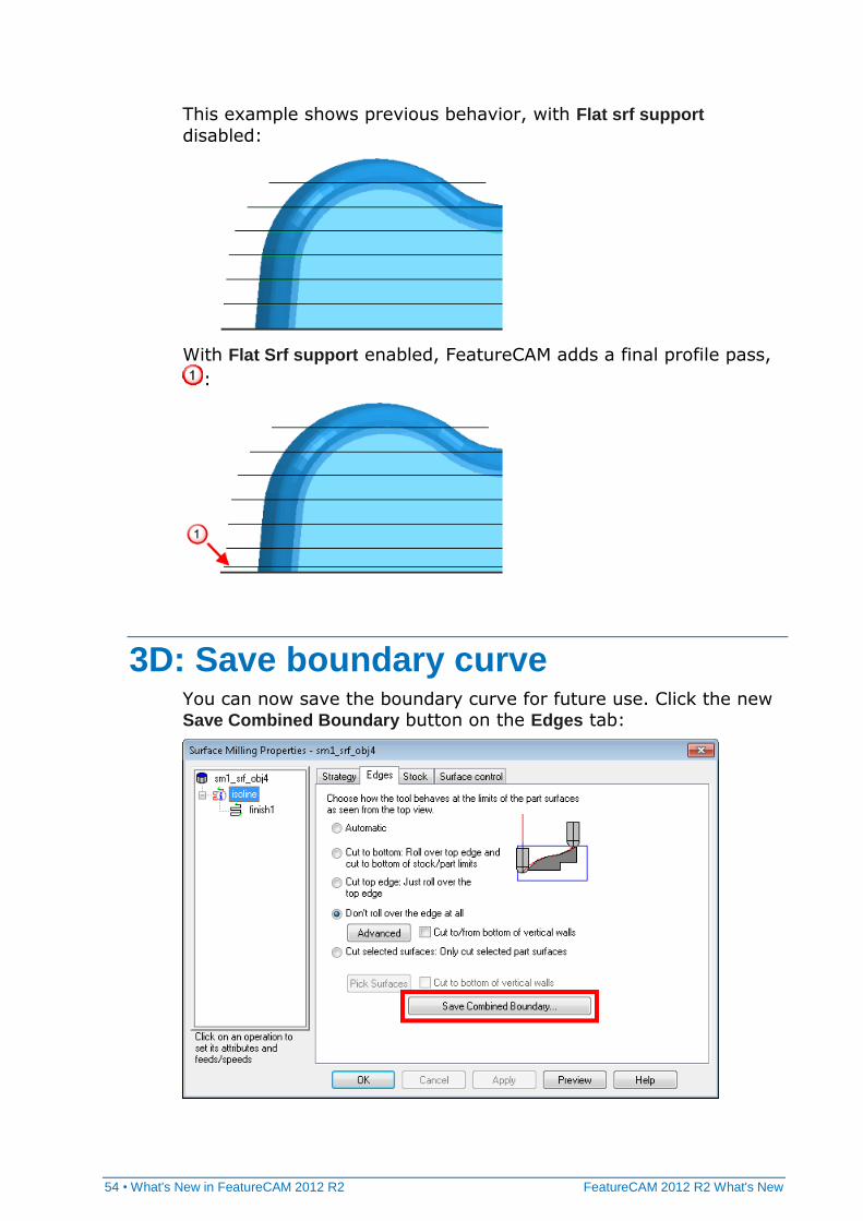
This example shows previous behavior, with Flat srf support
disabled:
With Flat Srf support enabled, FeatureCAM adds a final profile pass,
:
3D: Save boundary curve You can now save the boundary curve for future use. Click the new Save Combined Boundary button on the Edges tab:
FeatureCAM 2012 R2 What's New What's New in FeatureCAM 2012 R2 • 55
5-axis: Turn/Mill B-axis alternative position
In FeatureCAM 2012 R2, the Use alternative 5-axis position attribute is available on the Drilling and Milling tab for 2.5D milling operations
in Turn/Mill parts.
This means that you could cut 2.5D operations at, for example, B=-10 instead of the default +10 if the B-head has more clearance
tilting up.
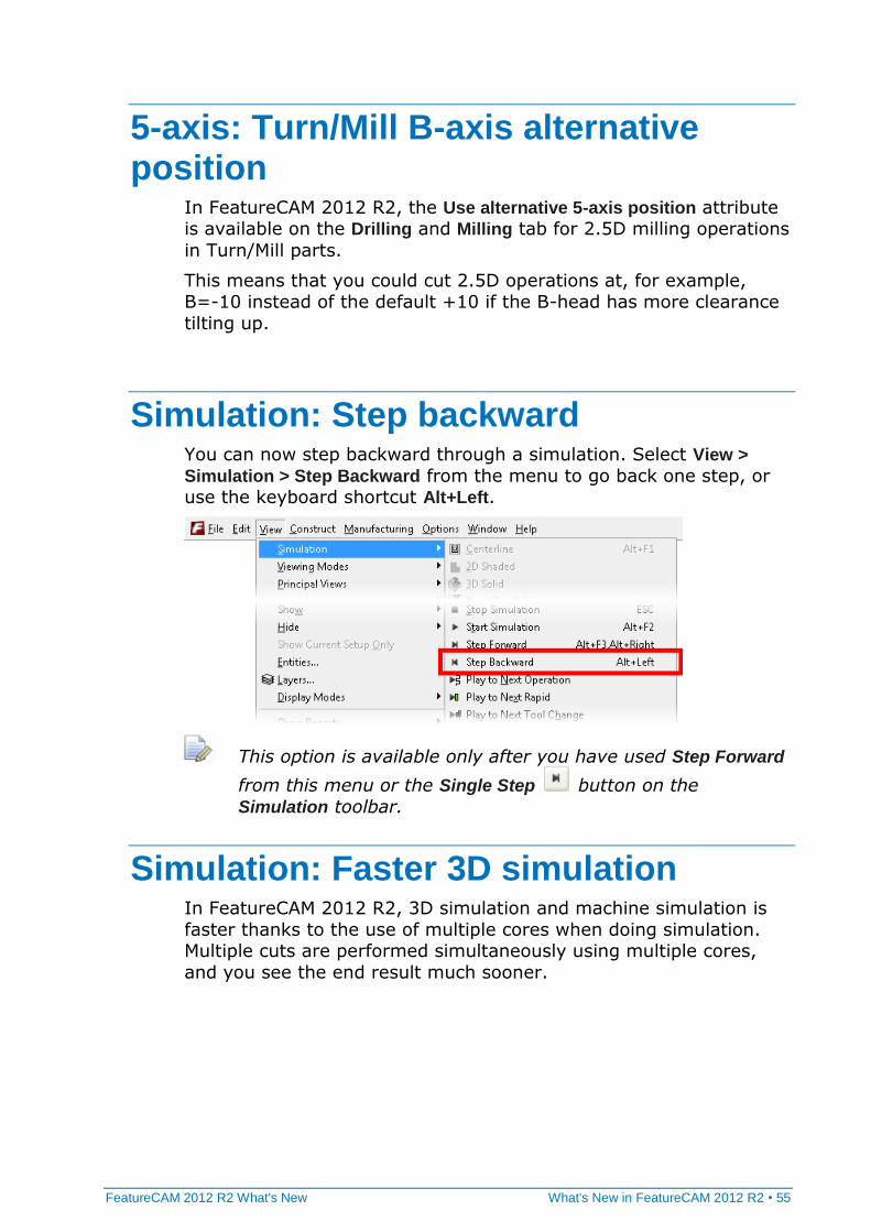
Simulation: Step backward You can now step backward through a simulation. Select View >
Simulation > Step Backward from the menu to go back one step, or use the keyboard shortcut Alt+Left.
This option is available only after you have used Step Forward
from this menu or the Single Step button on the
Simulation toolbar.
Simulation: Faster 3D simulation In FeatureCAM 2012 R2, 3D simulation and machine simulation is
faster thanks to the use of multiple cores when doing simulation. Multiple cuts are performed simultaneously using multiple cores,
and you see the end result much sooner.
56 • What's New in FeatureCAM 2012 R2 FeatureCAM 2012 R2 What's New
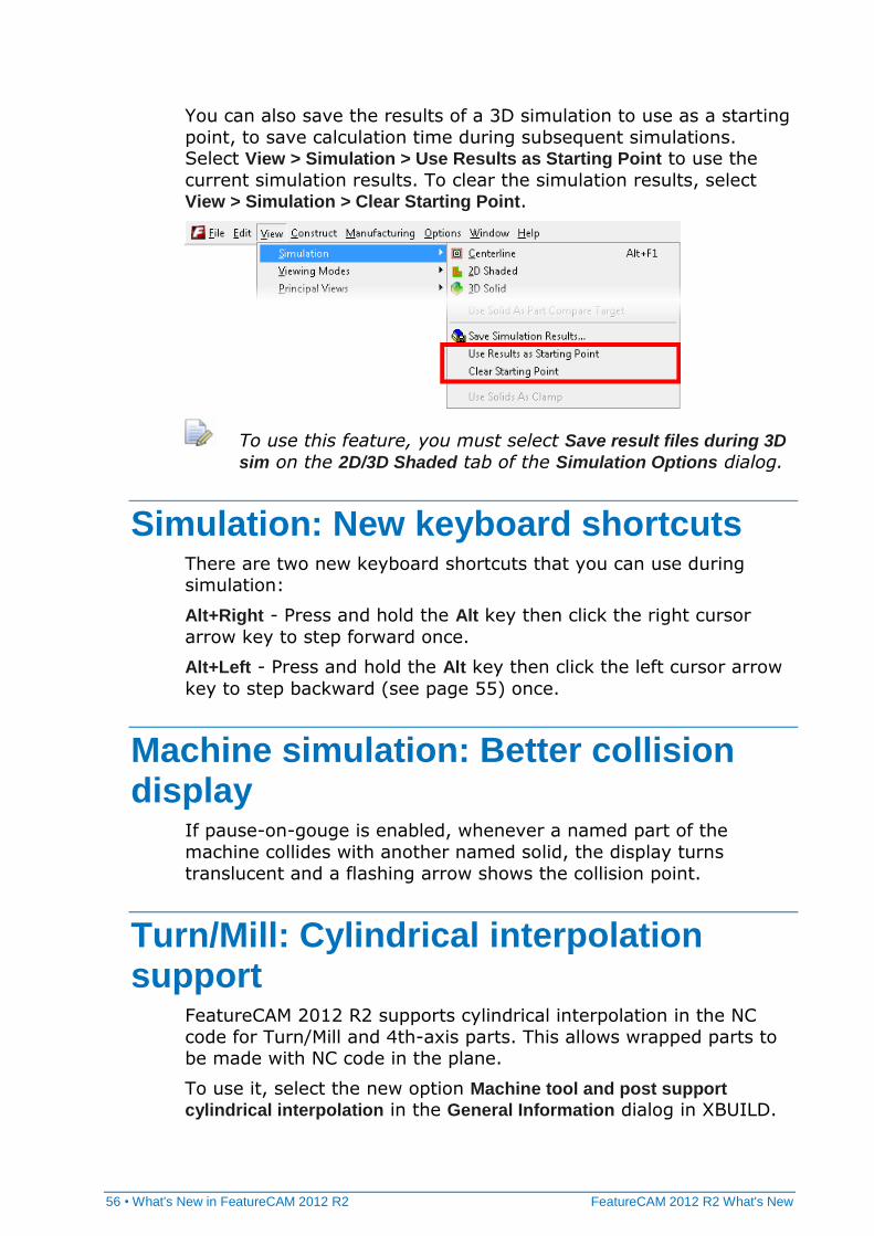
You can also save the results of a 3D simulation to use as a starting
point, to save calculation time during subsequent simulations. Select View > Simulation > Use Results as Starting Point to use the
current simulation results. To clear the simulation results, select View > Simulation > Clear Starting Point.
To use this feature, you must select Save result files during 3D
sim on the 2D/3D Shaded tab of the Simulation Options dialog.
Simulation: New keyboard shortcuts There are two new keyboard shortcuts that you can use during simulation:
Alt+Right - Press and hold the Alt key then click the right cursor
arrow key to step forward once.
Alt+Left - Press and hold the Alt key then click the left cursor arrow
key to step backward (see page 55) once.
Machine simulation: Better collision display
If pause-on-gouge is enabled, whenever a named part of the
machine collides with another named solid, the display turns
translucent and a flashing arrow shows the collision point.
Turn/Mill: Cylindrical interpolation support
FeatureCAM 2012 R2 supports cylindrical interpolation in the NC
code for Turn/Mill and 4th-axis parts. This allows wrapped parts to be made with NC code in the plane.
To use it, select the new option Machine tool and post support
cylindrical interpolation in the General Information dialog in XBUILD.
FeatureCAM 2012 R2 What's New What's New in FeatureCAM 2012 R2 • 57
Cylindrical interpolation uses these new reserved words:
<CYL-INTERP> - logical, TRUE if cylindrical interpolation is used
<WRAP-RADIUS> - numeric, the wrapping radius
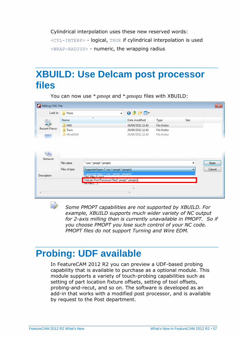
XBUILD: Use Delcam post processor files
You can now use *.pmopt and *.pmoptz files with XBUILD:
Some PMOPT capabilities are not supported by XBUILD. For
example, XBUILD supports much wider variety of NC output for 2-axis milling than is currently unavailable in PMOPT. So if
you choose PMOPT you lose such control of your NC code. PMOPT files do not support Turning and Wire EDM.
Probing: UDF available In FeatureCAM 2012 R2 you can preview a UDF-based probing
capability that is available to purchase as a optional module. This module supports a variety of touch-probing capabilities such as
setting of part location fixture offsets, setting of tool offsets, probing-and-recut, and so on. The software is developed as an
add-in that works with a modified post processor, and is available
by request to the Post department.
58 • What's New in FeatureCAM 2012 R2 FeatureCAM 2012 R2 What's New
API: New functions This is a summary of the new API functions, for more information please see the API help file.
FMToolpathPts.DeleteItem - Delete a toolpath point from list of
points.
FMToolpathPt.Dwell - Return and set the dwell time associated
with the toolpath point.
FMToolpathArc.Dwell - Return and set the dwell time associated
with the toolpath arc.
FMToolpathPts.AddtoolpathNCText - Create a toolpath NC text
segment.
FMToolpathNCText - A new class to represent the NC text segment.
FMFeatures.AddToolpathFromOperation - Create a toolpath
feature from an operation.
Application.SetGraphicsWinLowerColor - Set graphics window
lower background color.
Application.SetGraphicsWinUpperColor - Set graphics window
upper background color.
FMCurves.AddFunctionCurve - Create curve from function.
FMSurfaces.AddSurfaceCoons - Create a coons surface.
Other improvements Network database - The network database is now more reliable.
2.5D: Performance improvement for large STL stock.
Turn/Mill - The Disable Macros option is now available on the
Turn/Mill tab in the Post Options dialog.
FeatureCAM 2012 R2 What's New Index • 59
* *.pmopt files • 57 *.pmoptz files • 57
< <CYL-INTERP> • 56 <WRAP-RADIUS> • 56
4 4-axis part compare • 25
5 5-axis part compare • 25 5-axis position • 55
A Add NC code text • 18 Alternative 5-axis position • 55 API • 58 Approach from outside • 45
B Back bore cycle • 24 Back bore holes • 24 Back bore operation • 24 Backbore cycle • 24 Backbore holes • 24
Backbore operation • 24 B-axis Turn/Mill • 55 Bore (FDSJ) cycle • 52 Boundary curve • 54
C Chamfer feature • 52 Chamfer for face mill tools • 5 Clear starting point • 55 Combined boundary • 54 Configurations • 38 Connecting toolpath segments • 18 Continuous Spiral • 40 Continuous spiral (3D) • 27 Create Toolpath feature • 18 Cut type • 40 Cutter length • 13 Cutting data • 6 Cylindrical interpolation • 56
D Delete segment (Toolpath feature) • 18 Delete Toolpath Segment dialog • 18 Depth • 6, 13 Depth % • 13 Depth of cut • 6 Depth of cut order of importance • 13 Depth of cut precedence • 13 Depth of cut priority • 13 Depth override • 6 Diameter of tool • 13 Direct (ramp type) • 45 Direct move between 2 segments • 18 Display lines (Toolpath feature) • 18
Index
60 • Index FeatureCAM 2012 R2 What's New
Dwell • 18
E Edit segment • 18 Edit Toolpath Segment dialog • 18 Effective diameter • 5 Equal depth of cut • 13, 22 Exact Z step • 22
F Face mill tools • 5 Face Mill tools • 52 Family Tables (Pro/E) • 40 Feed • 6 Feed Dir. (Thread Mill) • 51 Feed/Speed tab • 6, 13 Feeds and speeds • 6 File configurations • 38 Finish depth of cut • 13 Finish pass total stock • 17 Finish pass Z increment • 13 Flat surface support • 53
G G74 (left-handed tapping cycle) • 52 G88 (boring cycle) • 52
H Handedness (Thread Mill tools) • 51 Holder Drawing tab (TURN) • 28 Hot keys • 3 HSM max tool overload % • 40 HSM profile corner % • 40 HSM smoothing allowance % • 40
I Islands • 45 Isometric views • 1
K Keyboard shortcuts • 3, 56
L Lead distance in % • 50 Lead distance out % • 50 Lead-in options • 45 Lead-out options • 45 Leave allowance (TURN) • 37
M Machining configurations • 38 Material-based tool settings • 6 Max. ramp angle • 45 Max. tool overload % (HSM) • 40 Milling tab • 13 Min.rapid distance % • 45 Minimize tool retract • 46 Misc. tab • 13 Multi-height islands • 45 Multiple select in Part View • 4
N Negative leave allowance (TURN) • 37 Negative Z • 51 Network database • 38 New technology toolpaths • 40 NT Continuous Spiral • 40 NT Spiral • 40 NT toolpaths • 40 NT Zigzag • 40
O Operation-based tool settings • 6 Order of importance for depth of cut • 13 Override depth • 6 Override depth of cut • 6 Override ramp angle • 6 Override stepover • 6 Override tool depth • 6 Override tool ramp angle • 6 Override tool stepover • 6 Overrides tab • 6, 13
P Part compare • 25
FeatureCAM 2012 R2 What's New Index • 61
Part compare target • 25 Part View multiple select • 4 Personal configurations • 38 Plunge point(s) • 45 PMOPT files • 57 PMOPTZ files • 57 Positive Z (Feed Dir.) • 51 PowerSHAPE • 40 Precedence of depth of cut • 13 Pre-drill • 45 Priority of depth of cut • 13 Pro/E • 40 Probing • 57 Profile corner % (HSM) • 40
R Ramp angle • 6 Ramp type • 45 Retract • 46 Retract to rapid plane, rapid move to
next segment • 18 Retract to specified Z value, rapid move
to next segment • 18 Reverse tab cycle • 52 Reverse-bore holes • 24 Rough depth of cut • 13 Rough pass Z increment • 13 Rough stepover options • 40
S Save combined boundary • 54 Settings • 38 Shared settings • 38 Shortcut keys • 3 Show part compare • 25 Simulation • 55, 56 Simulation improvements • 25 Smooth (ramp type) • 45 Smoothing allowance % (HSM) • 40 Solid model tool holder (TURN) • 28 SolidEdge ST4 • 40 Speed • 6 Spiral • 40 Spiral roughing (3D) • 27 Starting point (Simulation) • 55 Step backward • 55 Stepover • 6, 40
Stepover Options • 40 Stepover override • 6 Stepover rapid distance • 45 Stepover tab (Machining Attributes) • 40 Stepover type • 40 Stepovers tab • 13 Stepovers tab (Feature Properties) • 40 Strategy tab (Feature Properties) • 40
T Thread Mill hand • 51 Tool attributes • 6 Tool depth • 6 Tool depth override • 6 Tool diameter • 13 Tool holder graphics (TURN) • 36 Tool holder solid model (TURN) • 28 Tool overrides tab • 6 Tool properties • 6 Tool settings • 6 Tool specific feeds and speeds • 6 Toolpath feature • 18 Toolpath options • 18 Toolpaths tab • 18 Total stock • 17 Total stock for finish pass • 17 Turn part compare • 25 Turn/Mill B-axis • 55 Turn/mill part compare • 25 Turning leave allowance • 37
U Undo Toolpath edits • 18 Use alternative 5-axis position • 55 Use results as starting point • 55 Use solid as part compare target • 25 User interface • 1, 3, 4
W Wire part compare • 25 Workgroup configurations • 38
X X leave allowance (TURN) • 37
62 • Index FeatureCAM 2012 R2 What's New
Z Z leave allowance (TURN) • 37 Zigzag • 40 Z-level finish (3D) • 53 Z-level spiral rough (3D) • 27 Z-step increment • 6