Embed Size (px)
Citation preview
RE 51447, edition: 2014-11, Bosch Rexroth AG
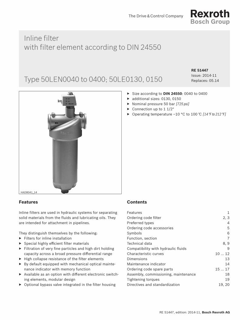
Inline filter with filter element according to DIN 24550
Features
Inline filters are used in hydraulic systems for separating solid materials from the fluids and lubricating oils. They are intended for attachment in pipelines.
They distinguish themselves by the following: ▶ Filters for inline installation ▶ Special highly efficient filter materials ▶ Filtration of very fine particles and high dirt holding
capacity across a broad pressure differential range ▶ High collapse resistance of the filter elements ▶ By default equipped with mechanical optical mainte-
nance indicator with memory function ▶ Available as an option with different electronic switch-
ing elements, modular design ▶ Optional bypass valve integrated in the filter housing
Contents
Features 1Ordering code filter 2, 3Preferred types 4Ordering code accessories 5Symbols 6Function, section 7Technical data 8, 9Compatibility with hydraulic fluids 9Characteristic curves 10 … 12Dimensions 13Maintenance indicator 14Ordering code spare parts 15 … 17Assembly, commissioning, maintenance 18Tightening torques 19Directives and standardization 19, 20
▶ Size according to DIN 24550: 0040 to 0400 ▶ additional sizes: 0130, 0150 ▶ Nominal pressure 50 bar [725 psi] ▶ Connection up to 1 1/2" ▶ Operating temperature –10 °C to 100 ℃ [14 °F to 212 °F]
RE 51447 Issue: 2014-11Replaces: 05.14
HAD8041_14
Type 50LEN0040 to 0400; 50LE0130, 0150
Contents
Features 1Contents 1Ordering code filter 2Ordering code filter 3Preferred types 4Ordering code accessories(dimensions in mm [inch]) 5Electronic switching element for maintenance indicators 5Mating connectors according to IEC 60947-5-2 5Symbols 6Function, section 7Technical data (For applications outside these parameters, please consult us!) 8Technical data (For applications outside these parameters, please consult us!) 9Compatibility with hydraulic fluids 9Characteristic curves H3XL (measured with mineral oil HLP46 according to DIN 51524 at T = 40°C) [104 °F]) 10Characteristic curves H3XL; H10XL (measured with mineral oil HLP46 according to DIN 51524 at T = 40°C) [104 °F]) 11Characteristic curves H10XL (measured with mineral oil HLP46 according to DIN 51524 at T = 40°C) [104 °F]) 12Dimensions: Size 0040 - size 0400 (dimensions in mm [inch]) 13Maintenance indicator (dimensions in mm [inch]) 14Ordering code spare parts 15Ordering code spare parts 16Ordering code spare parts 17Assembly, commissioning, maintenance 18Tightening torques (dimensions in mm [inch]) 19Directives and standardization 19Directives and standardization 19Directives and standardization 20Directives and standardization 20
2/20 50LEN0040-0400; 50LE0130, 0150 | RE 51447
Bosch Rexroth AG, RE 51447, edition: 2014-11
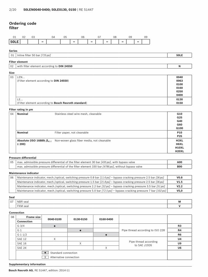
Ordering code filter
Series 01 Inline filter 50 bar [725 psi] 50LE
Filter element 02 with filter element according to DIN 24550 N
Size 03 LEN...
(Filter element according to DIN 24550)004000630100 0160 02500400
LE... (Filter element according to Bosch Rexroth standard)
01300150
Filter rating in μm04 Nominal Stainless steel wire mesh, cleanable G10
G25G40G60G100
Nominal Filter paper, not cleanable P10P25
Absolute (ISO 16889; βx(c) ≥ 200)
Non-woven glass fiber media, not cleanable H3XLH6XL
H10XLH20XL
Pressure differential 05 max. admissible pressure differential of the filter element 30 bar [435 psi], with bypass valve A00
max. admissible pressure differential of the filter element 330 bar [4786 psi], without bypass valve B00
Maintenance indicator 06 Maintenance indicator, mech./optical, switching pressure 0.8 bar [11.6 psi] – bypass cracking pressure 2.5 bar [36 psi] V0.8
Maintenance indicator, mech./optical, switching pressure 1.5 bar [21.8 psi] – bypass cracking pressure 2.5 bar [36 psi] V1.5Maintenance indicator, mech./optical, switching pressure 2.2 bar [32 psi] – bypass cracking pressure 3.5 bar [51 psi] V2.2Maintenance indicator, mech./optical, switching pressure 5.0 bar [72.5 psi] – bypass cracking pressure 7 bar [102 psi] V5,0
Seal 07 NBR seal M
FKM seal V
Connection 08 Frame size
0040-0100 0130-0150 0160-0400ConnectionG 3/4 ●
Pipe thread according to ISO 228R3
G 1 ● R4G 1 1/2 ● R6SAE 12 X
Pipe thread according to SAE J1926
U4SAE 16 X U9SAE 24 X U6
● Standard connection X Alternative connection
Supplementary information
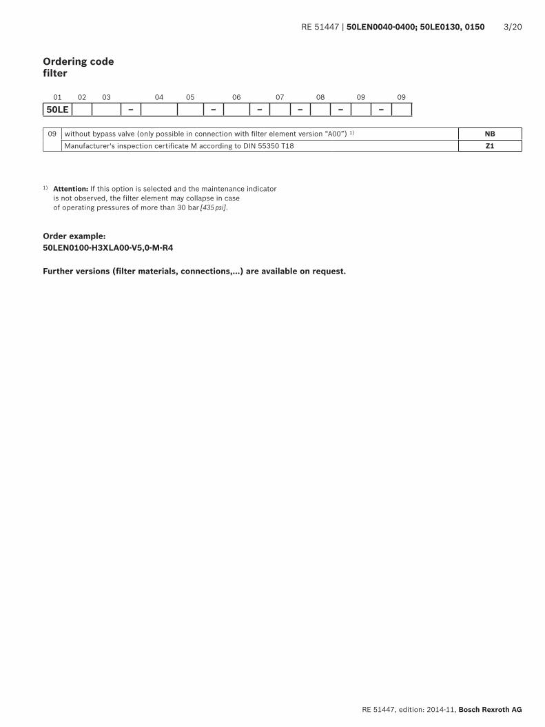
01 02 03 04 05 06 07 08 09 09
50LE – – – – – –
RE 51447 | 50LEN0040-0400; 50LE0130, 0150 3/20
RE 51447, edition: 2014-11, Bosch Rexroth AG
Ordering code filter
01 02 03 04 05 06 07 08 09 09
50LE – – – – – –
09 without bypass valve (only possible in connection with filter element version “A00”) 1) NBManufacturer's inspection certificate M according to DIN 55350 T18 Z1
1) Attention: If this option is selected and the maintenance indicator is not observed, the filter element may collapse in case of operating pressures of more than 30 bar [435 psi].
Order example: 50LEN0100-H3XLA00-V5,0-M-R4
Further versions (filter materials, connections,...) are available on request.
4/20 50LEN0040-0400; 50LE0130, 0150 | RE 51447
Bosch Rexroth AG, RE 51447, edition: 2014-11
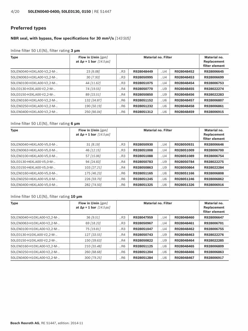
Preferred types
NBR seal, with bypass, flow specifications for 30 mm2/s [143 SUS]
Inline filter 50 LE(N), filter rating 3 μmType Flow in l/min [gpm]
at Δp = 1 bar [14.5 psi]Material no. Filter Material no.
Replacement filter element
50LEN0040-H3XLA00-V2,2-M-.. 23 [6.08] ..R3 R928048449 ..U4 R928048452 R928006645
50LEN0063-H3XLA00-V2,2-M-.. 30 [7.93] ..R3 R928050995 ..U4 R928048453 R928006699
50LEN0100-H3XLA00-V2,2-M-.. 44 [11.62] ..R3 R928051075 ..U4 R928048454 R928006753
50LE0130-H3XLA00-V2,2-M-.. 74 [19.55] ..R4 R928050770 ..U9 R928048455 R928022274
50LE0150-H3XLA00-V2,2-M-.. 89 [23.51] ..R4 R928050850 ..U9 R928048456 R928022283
50LEN0160-H3XLA00-V2,2-M-.. 132 [34.87] ..R6 R928051152 ..U6 R928048457 R928006807
50LEN0250-H3XLA00-V2,2-M-.. 190 [50.19] ..R6 R928051232 ..U6 R928048458 R928006861
50LEN0400-H3XLA00-V2,2-M-.. 250 [66.04] ..R6 R928051312 ..U6 R928048459 R928006915
Inline filter 50 LE(N), filter rating 6 μmType Flow in l/min [gpm]
at Δp = 1 bar [14.5 psi]Material no. Filter Material no.
Replacement filter element
50LEN0040-H6XLA00-V5,0-M-.. 31 [8.19] ..R3 R928050930 ..U4 R928050931 R928006646
50LEN0063-H6XLA00-V5,0-M-.. 46 [12.15] ..R3 R928051008 ..U4 R928051009 R928006700
50LEN0100-H6XLA00-V5,0-M-.. 57 [15.06] ..R3 R928051088 ..U4 R928051089 R928006754
50LE0130-H6XLA00-V5,0-M-.. 94 [24.83] ..R4 R928050783 ..U9 R928050784 R928022275
50LE0150-H6XLA00-V5,0-M-.. 103 [27.21] ..R4 R928050863 ..U9 R928050864 R928022284
50LEN0160-H6XLA00-V5,0-M-.. 175 [46.23] ..R6 R928051165 ..U6 R928051166 R928006808
50LEN0250-H6XLA00-V5,0-M-.. 226 [59.70] ..R6 R928051245 ..U6 R928051246 R928006862
50LEN0400-H6XLA00-V5,0-M-.. 282 [74.50] ..R6 R928051325 ..U6 R928051326 R928006916
Inline filter 50 LE(N), filter rating 10 μmType Flow in l/min [gpm]
at Δp = 1 bar [14.5 psi]Material no. Filter Material no.
Replacement filter element
50LEN0040-H10XLA00-V2,2-M-.. 36 [9.51] ..R3 R928047959 ..U4 R928048460 R928006647
50LEN0063-H10XLA00-V2,2-M-.. 69 [18.23] ..R3 R928050967 ..U4 R928048461 R928006701
50LEN0100-H10XLA00-V2,2-M-.. 75 [19.81] ..R3 R928051047 ..U4 R928048462 R928006755
50LE0130-H10XLA00-V2,2-M-.. 127 [33.55] ..R4 R928050743 ..U9 R928048463 R928022276
50LE0150-H10XLA00-V2,2-M-.. 150 [39.63] ..R4 R928050822 ..U9 R928048464 R928022285
50LEN0160-H10XLA00-V2,2-M-.. 210 [55.48] ..R6 R928051125 ..U6 R928048465 R928006809
50LEN0250-H10XLA00-V2,2-M-.. 260 [68.68] ..R6 R928051204 ..U6 R928048466 R928006863
50LEN0400-H10XLA00-V2,2-M-.. 300 [79.25] ..R6 R928051284 ..U6 R928048467 R928006917
������������
��
���
�����
����
���
��
���
��� ��
����
�����������
RE 51447 | 50LEN0040-0400; 50LE0130, 0150 5/20
RE 51447, edition: 2014-11, Bosch Rexroth AG
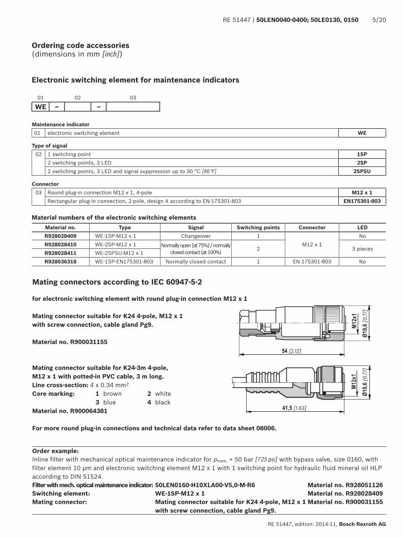
Ordering code accessories (dimensions in mm [inch])
Electronic switching element for maintenance indicators
Maintenance indicator01 electronic switching element WE
Type of signal02 1 switching point 1SP
2 switching points, 3 LED 2SP2 switching points, 3 LED and signal suppression up to 30 °C [86 °F] 2SPSU
Connector03 Round plug-in connection M12 x 1, 4-pole M12 x 1
Rectangular plug-in connection, 2-pole, design A according to EN-175301-803 EN175301-803
01 02 03
WE – –
Material numbers of the electronic switching elementsMaterial no. Type Signal Switching points Connector LEDR928028409 WE-1SP-M12 x 1 Changeover 1
M12 x 1No
R928028410 WE-2SP-M12 x 1 Normally open (at 75%) / normally closed contact (at 100%) 2 3 pieces
R928028411 WE-2SPSU-M12 x 1R928036318 WE-1SP-EN175301-803 Normally closed contact 1 EN 175301-803 No
Order example:Inline filter with mechanical optical maintenance indicator for pnom. = 50 bar [725 psi] with bypass valve, size 0160, with filter element 10 μm and electronic switching element M12 x 1 with 1 switching point for hydraulic fluid mineral oil HLP according to DIN 51524.Filter with mech. optical maintenance indicator: 50LEN0160-H10XLA00-V5,0-M-R6 Material no. R928051126Switching element: WE-1SP-M12 x 1 Material no. R928028409Mating connector: Mating connector suitable for K24 4-pole, M12 x 1
with screw connection, cable gland Pg9.Material no. R900031155
Mating connectors according to IEC 60947-5-2
Mating connector suitable for K24 4-pole, M12 x 1 with screw connection, cable gland Pg9.
Material no. R900031155
for electronic switching element with round plug-in connection M12 x 1
Mating connector suitable for K24-3m 4-pole, M12 x 1 with potted-in PVC cable, 3 m long. Line cross-section: 4 x 0.34 mm2
Core marking: 1 brown 2 white 3 blue 4 blackMaterial no. R900064381
For more round plug-in connections and technical data refer to data sheet 08006.
�
�
�
�
���������
����
����
�������
�
����� ����
��������
����� �������
��
����
����
�
����
6/20 50LEN0040-0400; 50LE0130, 0150 | RE 51447
Bosch Rexroth AG, RE 51447, edition: 2014-11
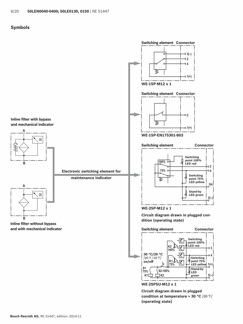
Inline filter with bypass and mechanical indicator
Inline filter without bypass and with mechanical indicator
Symbols
Electronic switching element for
maintenance indicator
WE-1SP-M12 x 1
WE-1SP-EN175301-803
Switching element Connector
Switching point 100% LED red
Switching point 75% LED yellowStand-by LED green
30 °C/20 °C[86 °F / 68 °F]on/off
WE-2SPSU-M12 x 1
Circuit diagram drawn in plugged condition at temperature > 30 °C [86 °F] (operating state)
WE-2SP-M12 x 1
Circuit diagram drawn in plugged con-dition (operating state)
Switching element Connector
Switching point 100% LED red
Switching point 75% LED yellow
Stand-by LED green
Switching element
Switching element
Connector
Connector
�
�
�
�
�
�
�
�
RE 51447 | 50LEN0040-0400; 50LE0130, 0150 7/20
RE 51447, edition: 2014-11, Bosch Rexroth AG
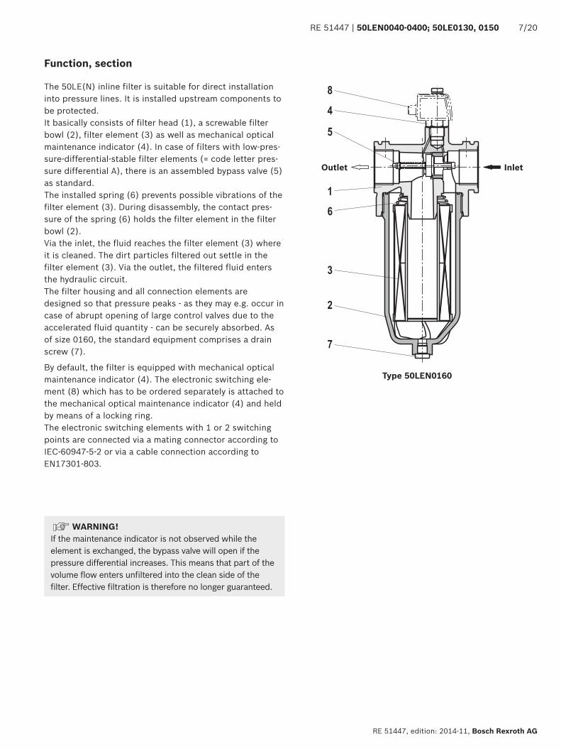
Function, section
The 50LE(N) inline filter is suitable for direct installation into pressure lines. It is installed upstream components to be protected.It basically consists of filter head (1), a screwable filter bowl (2), filter element (3) as well as mechanical optical maintenance indicator (4). In case of filters with low-pres-sure-differential-stable filter elements (= code letter pres-sure differential A), there is an assembled bypass valve (5) as standard.The installed spring (6) prevents possible vibrations of the filter element (3). During disassembly, the contact pres-sure of the spring (6) holds the filter element in the filter bowl (2).Via the inlet, the fluid reaches the filter element (3) where it is cleaned. The dirt particles filtered out settle in the filter element (3). Via the outlet, the filtered fluid enters the hydraulic circuit.The filter housing and all connection elements are designed so that pressure peaks - as they may e.g. occur in case of abrupt opening of large control valves due to the accelerated fluid quantity - can be securely absorbed. As of size 0160, the standard equipment comprises a drain screw (7).
By default, the filter is equipped with mechanical optical maintenance indicator (4). The electronic switching ele-ment (8) which has to be ordered separately is attached to the mechanical optical maintenance indicator (4) and held by means of a locking ring.The electronic switching elements with 1 or 2 switching points are connected via a mating connector according to IEC-60947-5-2 or via a cable connection according to EN17301-803.
Type 50LEN0160
InletOutlet
WARNING! If the maintenance indicator is not observed while the element is exchanged, the bypass valve will open if the pressure differential increases. This means that part of the volume flow enters unfiltered into the clean side of the filter. Effective filtration is therefore no longer guaranteed.
8/20 50LEN0040-0400; 50LE0130, 0150 | RE 51447
Bosch Rexroth AG, RE 51447, edition: 2014-11
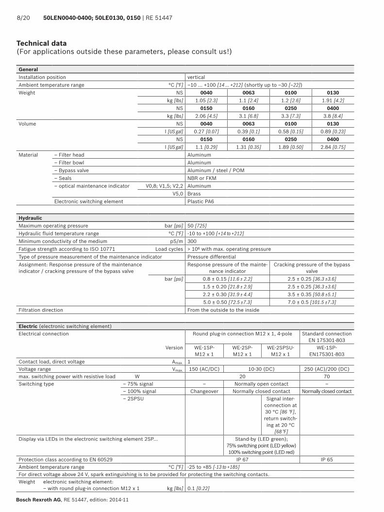
Technical data (For applications outside these parameters, please consult us!)
GeneralInstallation position vertical Ambient temperature range °C [°F] ‒10 ... +100 [14 ... +212] (shortly up to ‒30 [‒22])Weight NS 0040 0063 0100 0130
kg [lbs] 1.05 [2.3] 1.1 [2.4] 1.2 [2.6] 1.91 [4.2]NS 0150 0160 0250 0400
kg [lbs] 2.06 [4.5] 3.1 [6.8] 3.3 [7.3] 3.8 [8.4]Volume NS 0040 0063 0100 0130
l [US gal] 0.27 [0.07] 0.39 [0.1] 0.58 [0.15] 0.89 [0.23]NS 0150 0160 0250 0400
l [US gal] 1.1 [0.29] 1.31 [0.35] 1.89 [0.50] 2.84 [0.75]Material – Filter head Aluminum
– Filter bowl Aluminum– Bypass valve Aluminum / steel / POM– Seals NBR or FKM– optical maintenance indicator V0,8; V1,5; V2,2 Aluminum
V5,0 BrassElectronic switching element Plastic PA6
HydraulicMaximum operating pressure bar [psi] 50 [725]Hydraulic fluid temperature range °C [°F] -10 to +100 [+14 to +212]Minimum conductivity of the medium pS/m 300Fatigue strength according to ISO 10771 Load cycles > 106 with max. operating pressureType of pressure measurement of the maintenance indicator Pressure differentialAssignment: Response pressure of the maintenance indicator / cracking pressure of the bypass valve
Response pressure of the mainte-nance indicator
Cracking pressure of the bypass valve
bar [psi] 0.8 ± 0.15 [11.6 ± 2.2] 2.5 ± 0.25 [36.3 ±3.6]1.5 ± 0.20 [21.8 ± 2.9] 2.5 ± 0.25 [36.3 ±3.6]2.2 ± 0.30 [31.9 ± 4.4] 3.5 ± 0.35 [50.8 ±5.1]5.0 ± 0.50 [72.5 ±7.3] 7.0 ± 0.5 [101.5 ±7.3]
Filtration direction From the outside to the inside
Electric (electronic switching element)Electrical connection Round plug-in connection M12 x 1, 4-pole Standard connection
EN 175301-803Version WE-1SP-
M12 x 1 WE-2SP-M12 x 1
WE-2SPSU-M12 x 1
WE-1SP-EN175301-803
Contact load, direct voltage Amax. 1Voltage range Vmax. 150 (AC/DC) 10-30 (DC) 250 (AC)/200 (DC)max. switching power with resistive load W 20 70Switching type – 75% signal – Normally open contact –
– 100% signal Changeover Normally closed contact Normally closed contact– 2SPSU Signal inter-
connection at 30 °C [86 °F], return switch-ing at 20 °C
[68 °F]Display via LEDs in the electronic switching element 2SP... Stand-by (LED green);
75% switching point (LED yellow) 100% switching point (LED red)
Protection class according to EN 60529 IP 67 IP 65Ambient temperature range °C [°F] -25 to +85 [-13 to +185]For direct voltage above 24 V, spark extinguishing is to be provided for protecting the switching contacts.Weight electronic switching element:
– with round plug-in connection M12 x 1 kg [lbs] 0.1 [0.22]
RE 51447 | 50LEN0040-0400; 50LE0130, 0150 9/20
RE 51447, edition: 2014-11, Bosch Rexroth AG
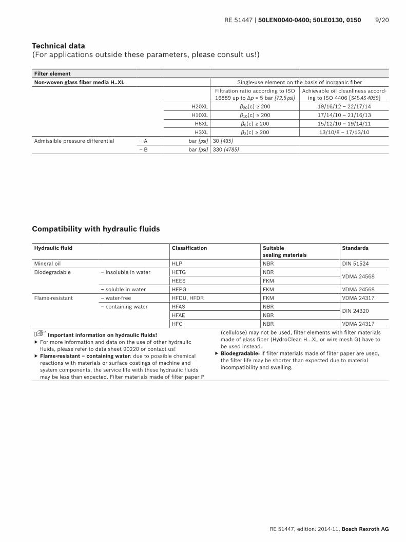
Technical data (For applications outside these parameters, please consult us!)
Filter elementNon-woven glass fiber media H..XL Single-use element on the basis of inorganic fiber
Filtration ratio according to ISO 16889 up to Δp = 5 bar [72.5 psi]
Achievable oil cleanliness accord-ing to ISO 4406 [SAE-AS 4059]
H20XL β20(c) ≥ 200 19/16/12 – 22/17/14H10XL β10(c) ≥ 200 17/14/10 – 21/16/13
H6XL β6(c) ≥ 200 15/12/10 – 19/14/11H3XL β3(c) ≥ 200 13/10/8 – 17/13/10
Admissible pressure differential – A bar [psi] 30 [435]– B bar [psi] 330 [4785]
Compatibility with hydraulic fluids
Hydraulic fluid Classification Suitable sealing materials
Standards
Mineral oil HLP NBR DIN 51524Biodegradable – insoluble in water HETG NBR
VDMA 24568HEES FKM
– soluble in water HEPG FKM VDMA 24568Flame-resistant – water-free HFDU, HFDR FKM VDMA 24317
– containing water HFAS NBRDIN 24320
HFAE NBRHFC NBR VDMA 24317
Important information on hydraulic fluids! ▶ For more information and data on the use of other hydraulic fluids, please refer to data sheet 90220 or contact us!
▶ Flame-resistant – containing water: due to possible chemical reactions with materials or surface coatings of machine and system components, the service life with these hydraulic fluids may be less than expected. Filter materials made of filter paper P
(cellulose) may not be used, filter elements with filter materials made of glass fiber (HydroClean H…XL or wire mesh G) have to be used instead.
▶ Biodegradable: If filter materials made of filter paper are used, the filter life may be shorter than expected due to material incompatibility and swelling.
�������������������������
���������������������������
�� ���� ��
���
���
���
���
���
����
�������������
����
����
����
����
����
�� ��
�����������
�� ���� ��
���
���
���
���
����
����
����
����
����
����
��� ������� ���� ����
�� ����� ��
���
���
���
���
���
����
�����������
����
����
����
����
����
�� ���
�������� ����
�� ���
���
���
���
���
���
����
����
����
����
����
����
����
�� ���
������������
���
����
�� ���
���
���
���
���
���
����
����
����
����
����
����
����
�� ���
������������
���
����
�� ���
���
���
���
���
���
����
����
����
����
����
����
����
�� ���
������������
���
����
10/20 50LEN0040-0400; 50LE0130, 0150 | RE 51447
Bosch Rexroth AG, RE 51447, edition: 2014-11
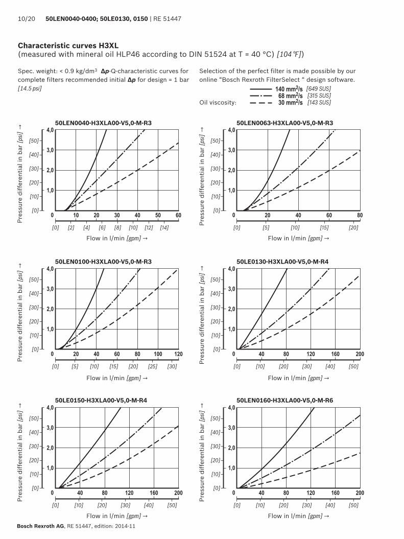
Characteristic curves H3XL (measured with mineral oil HLP46 according to DIN 51524 at T = 40 °C) [104 °F])
Selection of the perfect filter is made possible by our online “Bosch Rexroth FilterSelect “ design software.
Oil viscosity:
Spec. weight: < 0.9 kg/dm3 Δp-Q-characteristic curves for complete filters recommended initial Δp for design = 1 bar [14.5 psi]
50LEN0040-H3XLA00-V5,0-M-R3
Pres
sure
diff
eren
tial i
n ba
r [p
si] →
Flow in l/min [gpm] →
50LEN0063-H3XLA00-V5,0-M-R3
Pres
sure
diff
eren
tial i
n ba
r [p
si] →
Flow in l/min [gpm] →
50LEN0100-H3XLA00-V5,0-M-R3
Pres
sure
diff
eren
tial i
n ba
r [p
si] →
Flow in l/min [gpm] →
50LE0130-H3XLA00-V5,0-M-R4
Pres
sure
diff
eren
tial i
n ba
r [p
si] →
Flow in l/min [gpm] →
50LE0150-H3XLA00-V5,0-M-R4
Pres
sure
diff
eren
tial i
n ba
r [p
si] →
Flow in l/min [gpm] →
50LEN0160-H3XLA00-V5,0-M-R6
Pres
sure
diff
eren
tial i
n ba
r [p
si] →
Flow in l/min [gpm] →
�������������������������
���������������������������
��� ���
���
���
���
���
���
����
����
����
����
����
����
����
��� ���
�������������
���
�����
��� ����� ���
���
���
���
���
���
����
������������
����
����
����
����
����
��� ���
�������� ��������
�� ���� ��
���
���
���
���
����
����
����
����
����
����
��� ������� ���� ����
�� ���� ��
���
���
���
���
���
����
�������������
����
����
����
����
����
�� ��
�����������
RE 51447 | 50LEN0040-0400; 50LE0130, 0150 11/20
RE 51447, edition: 2014-11, Bosch Rexroth AG
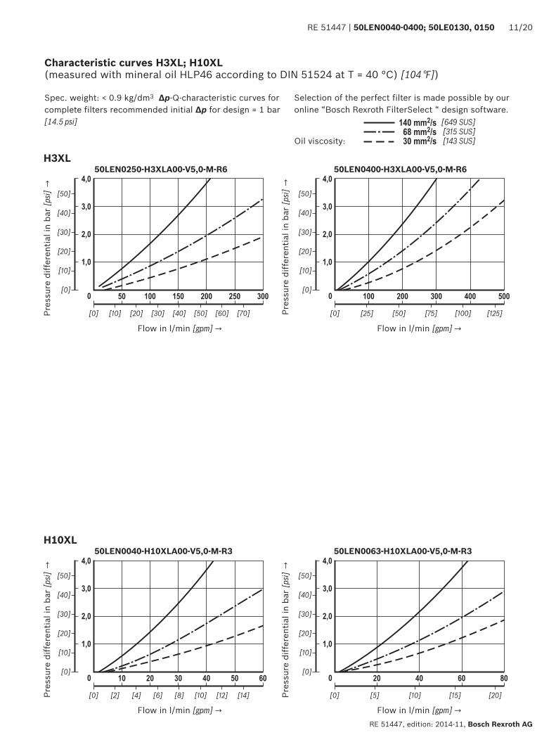
Characteristic curves H3XL; H10XL (measured with mineral oil HLP46 according to DIN 51524 at T = 40 °C) [104 °F])
Selection of the perfect filter is made possible by our online “Bosch Rexroth FilterSelect “ design software.
Oil viscosity:
Spec. weight: < 0.9 kg/dm3 Δp-Q-characteristic curves for complete filters recommended initial Δp for design = 1 bar [14.5 psi]
Pres
sure
diff
eren
tial i
n ba
r [p
si] →
50LEN0063-H10XLA00-V5,0-M-R3
Pres
sure
diff
eren
tial i
n ba
r [p
si] →
Flow in l/min [gpm] →
H3XL
H10XL
Pres
sure
diff
eren
tial i
n ba
r [p
si] →
50LEN0040-H10XLA00-V5,0-M-R3
Flow in l/min [gpm] →
50LEN0250-H3XLA00-V5,0-M-R6
Flow in l/min [gpm] →
50LEN0400-H3XLA00-V5,0-M-R6
Pres
sure
diff
eren
tial i
n ba
r [p
si] →
Flow in l/min [gpm] →
�������������������������
���������������������������
�� ����� ��
���
���
���
���
���
����
�����������
����
����
����
����
����
�� ���
�������� ����
�� ���
���
���
���
���
���
����
����
����
����
����
����
����
�� ���
������������
���
����
�� ���
���
���
���
���
���
����
����
����
����
����
����
����
�� ���
������������
���
����
�� ���
���
���
���
���
���
����
����
����
����
����
����
����
�� ���
������������
���
����
��� ����� ���
���
���
���
���
���
����
������������
����
����
����
����
����
��� ���
�������� ��������
��� ���
���
���
���
���
���
����
����
����
����
����
����
����
��� ���
�������������
���
�����
12/20 50LEN0040-0400; 50LE0130, 0150 | RE 51447
Bosch Rexroth AG, RE 51447, edition: 2014-11
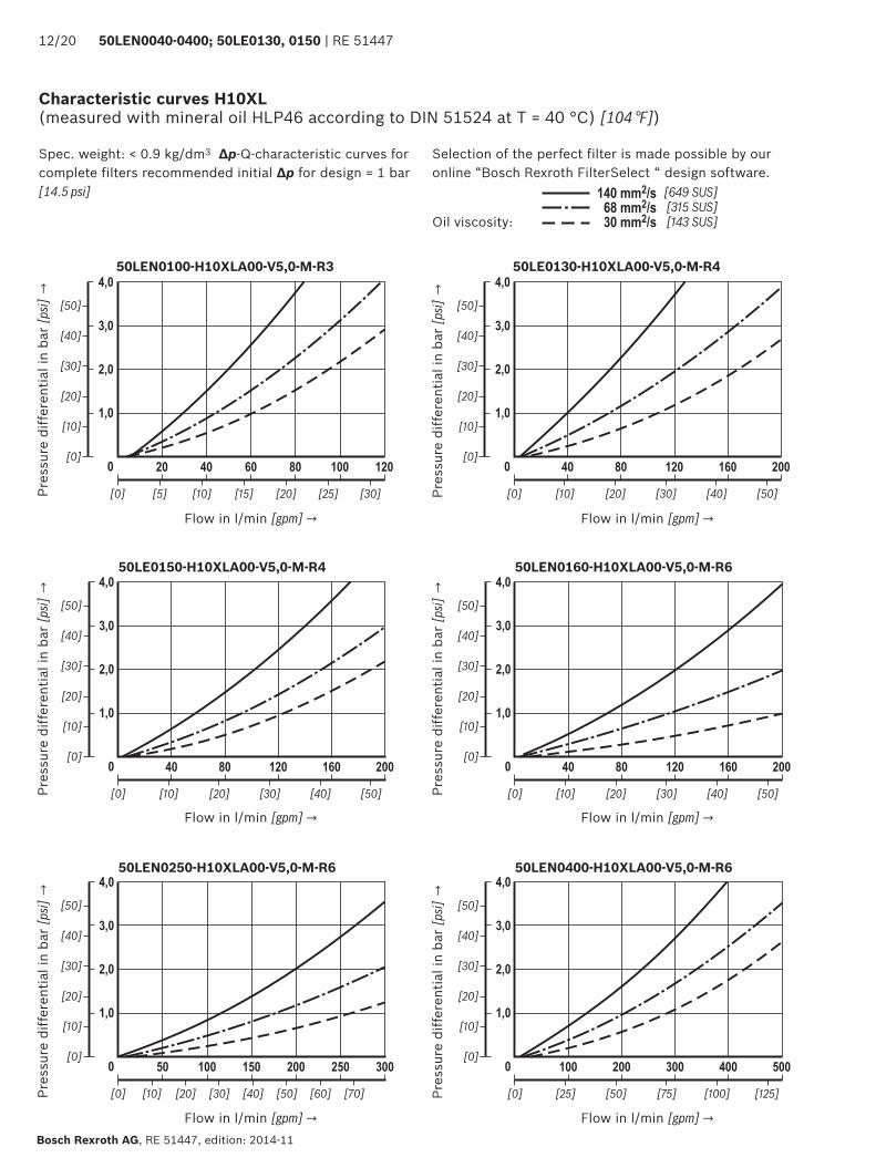
Characteristic curves H10XL (measured with mineral oil HLP46 according to DIN 51524 at T = 40 °C) [104 °F])
Selection of the perfect filter is made possible by our online “Bosch Rexroth FilterSelect “ design software.
Oil viscosity:
Spec. weight: < 0.9 kg/dm3 Δp-Q-characteristic curves for complete filters recommended initial Δp for design = 1 bar [14.5 psi]
50LE0150-H10XLA00-V5,0-M-R4
Pres
sure
diff
eren
tial i
n ba
r [p
si] →
Flow in l/min [gpm] →
50LEN0160-H10XLA00-V5,0-M-R6
Pres
sure
diff
eren
tial i
n ba
r [p
si] →
Flow in l/min [gpm] →
50LEN0250-H10XLA00-V5,0-M-R6
Pres
sure
diff
eren
tial i
n ba
r [p
si] →
Flow in l/min [gpm] →
50LEN0400-H10XLA00-V5,0-M-R6
Pres
sure
diff
eren
tial i
n ba
r [p
si] →
Flow in l/min [gpm] →
50LEN0100-H10XLA00-V5,0-M-R3
Pres
sure
diff
eren
tial i
n ba
r [p
si] →
Flow in l/min [gpm] →
50LE0130-H10XLA00-V5,0-M-R4
Pres
sure
diff
eren
tial i
n ba
r [p
si] →
Flow in l/min [gpm] →
��
��
��
����
����
����
��
�����
����
������
������
�
��
��
��
��
��
RE 51447 | 50LEN0040-0400; 50LE0130, 0150 13/20
RE 51447, edition: 2014-11, Bosch Rexroth AG
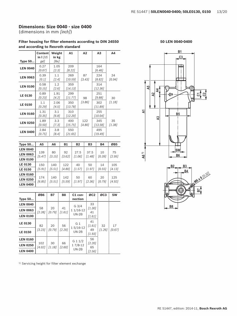
Dimensions: Size 0040 - size 0400 (dimensions in mm [inch])
50 LEN 0040-0400Filter housing for filter elements according to DIN 24550 and according to Rexroth standard
Type 50...
Content in l [US
gal]
Weight in kg [lbs]
A1 A2 A3 A4
LEN 0040 0.27[0.07]
1.05 [2.3]
209 [8.22]
87 [3.43]
164 [6.46]
24 [0.94]LEN 0063 0.39
[0.1]1.1
[2.4]269
[10.59]224
[8.82]
LEN 0100 0.58[0.15]
1.2 [2.6]
359 [14.13]
314 [12.36]
LE 0130 0.89[0.23]
1.91 [4.2]
299 [11.77] 98
[3.86]
251 [9.88] 30
[1.18]LE 0150 1.1
[0.29]2.06 [4.5]
350 [13.78]
302 [11.89]
LEN 0160 1.31[0.35]
3.1 [6.8]
310 [12.20]
122 [4.80]
255 [10.04]
35 [1.38]LEN 0250 1.89
[0.50]3.3
[7.3]400
[15.75]345
[13.58]
LEN 0400 2.84[0.75]
3.8 [8.4]
550 [21.65]
495 [19.49]
Type 50...ØB6 B7 B8 C1 con-
nectionØC2 ØC3 SW
LEN 004058
[2.28]20
[0.79]41
[1.61]
G 3/4 1 1/16-12
UN-2B
33 [1.30]
41 [1.61]
32 [1.26]
17 [0.67]
LEN 0063
LEN 0100
LE 013082
[3.23]20
[0.79]56
[2.20]
G 1 1 5/16-12
UN-2B
41 [1.61]
49 [1.93]LE 0150
LEN 0160102
[4.02]30
[1.18]66
[2.60]
G 1 1/2 1 7/8-12 UN-2B
56 [2.20]
65 [2.56]
LEN 0250
LEN 0400
Type 50... A5 A6 B1 B2 B3 B4 ØB5LEN 0040
139 [5.47]
80 [3.15]
92 [3.62]
27.5 [1.06]
37.5 [1.48]
10 [0.39]
75 [2.95]LEN 0063
LEN 0100LE 0130 150
[5.91]140
[5.51]122
[4.80]40
[1.57]50
[1.97]14
[0.55]105
[4.13]LE 0150LEN 0160
174 [6.85]
140 [5.51]
142 [5.59]
50 [1.97]
60 [2.36]
20 [0.79]
125 [4.92]LEN 0250
LEN 0400
1) Servicing height for filter element exchange
��
����
�������
�������
�����������
�����������
�����������
����
�����
������
�����
����
�����
��
������
�
�
�
�
�
��
���������
����
������
�
�������
�����������
�����������
���������
����
�����
������
�����
����
�����
������
���
������
�
�
�
�
�
�
��
�����
14/20 50LEN0040-0400; 50LE0130, 0150 | RE 51447
Bosch Rexroth AG, RE 51447, edition: 2014-11
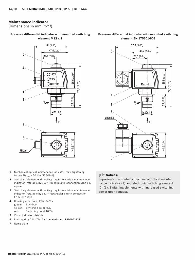
Maintenance indicator (dimensions in mm [inch])
Pressure differential indicator with mounted switching element M12 x 1
Pressure differential indicator with mounted switching element EN-175301-803
1 Mechanical optical maintenance indicator; max. tightening torque MA max = 50 Nm [36.88 lb-ft]
2 Switching element with locking ring for electrical maintenance indicator (rotatable by 360°);round plug-in connection M12 x 1, 4-pole
3 Switching element with locking ring for electrical maintenance indicator (rotatable by 360°);rectangular plug-in connection EN175301-803
4 Housing with three LEDs: 24 V =green: Stand-byyellow: Switching point 75%red: Switching point 100%
5 Visual indicator bistable6 Locking ring DIN 471-16 x 1, material no. R9000039237 Name plate
Notices: Representation contains mechanical optical mainte-nance indicator (1) and electronic switching element (2) (3). Switching elements with increased switching power upon request.
RE 51447 | 50LEN0040-0400; 50LE0130, 0150 15/20
RE 51447, edition: 2014-11, Bosch Rexroth AG
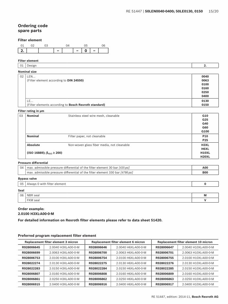
Ordering code spare parts
Filter element01 Design 2.
Nominal size02 LEN...
(Filter element according to DIN 24550)0040 0063 0100 0160 0250 0400
LE... (Filter elements according to Bosch Rexroth standard)
0130 0150
Filter rating in µm03 Nominal Stainless steel wire mesh, cleanable G10
G25G40 G60G100
Nominal Filter paper, not cleanable P10 P25
Absolute
(ISO 16889); βx(c) ≥ 200)
Non-woven glass fiber media, not cleanable H3XLH6XLH10XLH20XL
Pressure differential04 max. admissible pressure differential of the filter element 30 bar [435 psi] A00
max. admissible pressure differential of the filter element 330 bar [4786 psi] B00
Bypass valve
05 Always 0 with filter element 0
Seal06 NBR seal M
FKM seal V
01 02 03 04 05 06
2. – – 0 –
Filter element
Order example:2.0100 H3XL-A00-0-M
For detailed information on Rexroth filter elements please refer to data sheet 51420.
Replacement filter element 3 micron Replacement filter element 6 micron Replacement filter element 10 micron
R928006645 2.0040 H3XL-A00-0-M R928006646 2.0040 H6XL-A00-0-M R928006647 2.0040 H10XL-A00-0-M
R928006699 2.0063 H3XL-A00-0-M R928006700 2.0063 H6XL-A00-0-M R928006701 2.0063 H10XL-A00-0-M
R928006753 2.0100 H3XL-A00-0-M R928006754 2.0100 H6XL-A00-0-M R928006755 2.0100 H10XL-A00-0-M
R928022274 2.0130 H3XL-A00-0-M R928022275 2.0130 H6XL-A00-0-M R928022276 2.0130 H10XL-A00-0-M
R928022283 2.0150 H3XL-A00-0-M R928022284 2.0150 H6XL-A00-0-M R928022285 2.0150 H10XL-A00-0-M
R928006807 2.0160 H3XL-A00-0-M R928006808 2.0160 H6XL-A00-0-M R928006809 2.0160 H10XL-A00-0-M
R928006861 2.0250 H3XL-A00-0-M R928006862 2.0250 H6XL-A00-0-M R928006863 2.0250 H10XL-A00-0-M
R928006915 2.0400 H3XL-A00-0-M R928006916 2.0400 H6XL-A00-0-M R928006917 2.0400 H10XL-A00-0-M
Preferred program replacement filter element
16/20 50LEN0040-0400; 50LE0130, 0150 | RE 51447
Bosch Rexroth AG, RE 51447, edition: 2014-11
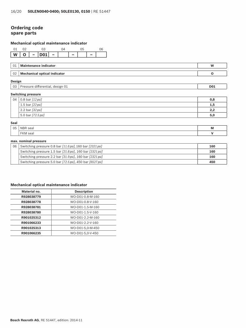
Ordering code spare parts
01 Maintenance indicator W
02 Mechanical optical indicator O
Design03 Pressure differential, design 01 D01
Switching pressure04 0.8 bar [12 psi] 0,8
1.5 bar [22 psi] 1,52.2 bar [32 psi] 2,25.0 bar [72.5 psi] 5,0
Seal05 NBR seal M
FKM seal V
max. nominal pressure06 Switching pressure 0.8 bar [11.6 psi], 160 bar [2321 psi] 160
Switching pressure 1.5 bar [21.8 psi], 160 bar [2321 psi] 160Switching pressure 2.2 bar [31.9 psi], 160 bar [2321 psi] 160Switching pressure 5.0 bar [72.5 psi], 450 bar [6527 psi] 450
01 02 03 04 05 06
W O – D01 – – –
Mechanical optical maintenance indicator
Mechanical optical maintenance indicator
Material no. DescriptionR928038779 WO-D01-0.8-M-160R928038778 WO-D01-0.8-V-160R928038781 WO-D01-1.5-M-160R928038780 WO-D01-1.5-V-160R901025312 WO-D01-2.2-M-160R901066233 WO-D01-2.2-V-160R901025313 WO-D01-5,0-M-450R901066235 WO-D01-5,0-V-450
RE 51447 | 50LEN0040-0400; 50LE0130, 0150 17/20
RE 51447, edition: 2014-11, Bosch Rexroth AG
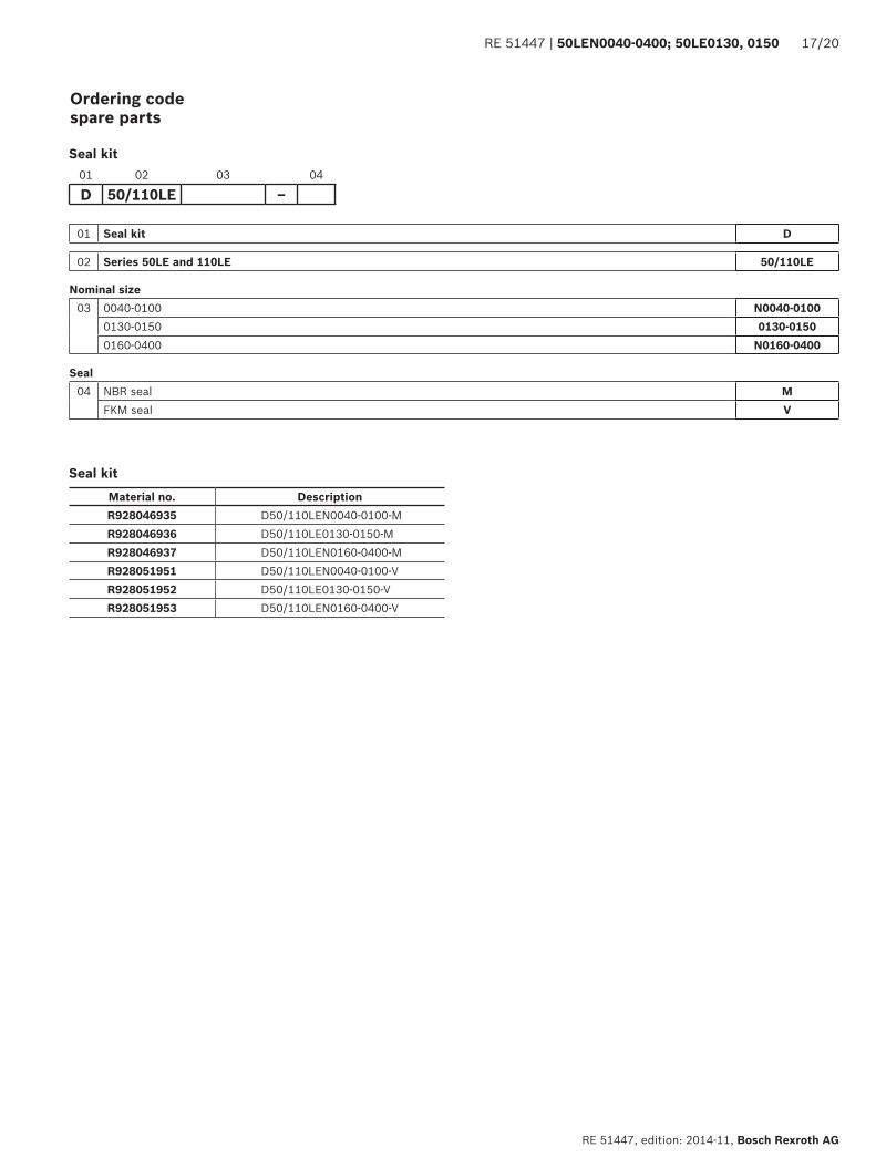
Ordering code spare parts
Material no. DescriptionR928046935 D50/110LEN0040-0100-M R928046936 D50/110LE0130-0150-M R928046937 D50/110LEN0160-0400-M R928051951 D50/110LEN0040-0100-V R928051952 D50/110LE0130-0150-V R928051953 D50/110LEN0160-0400-V
01 Seal kit D
02 Series 50LE and 110LE 50/110LE
Nominal size03 0040-0100 N0040-0100
0130-0150 0130-01500160-0400 N0160-0400
Seal04 NBR seal M
FKM seal V
01 02 03 04
D 50/110LE –
Seal kit
Seal kit
18/20 50LEN0040-0400; 50LE0130, 0150 | RE 51447
Bosch Rexroth AG, RE 51447, edition: 2014-11
Assembly, commissioning, maintenance
InstallationThe max. operating pressure of the system must not exceed the max. admissible operating pressure of the filter (see type plate). During assembly of the filter (see also chapter “Tightening torque”), the flow direction (direction arrows) and the required servicing height of the filter element (see chapter “Dimensions”) are to be considered.
Easy filter element exchange is guaranteed in the installa-tion position filter bowl vertically downwards. The mainte-nance indicator must be arranged in a well visible way.
Remove the plastic plugs in the filter inlet and outlet.
Ensure that the system is assembled without tension stress. The optional electronic maintenance indicator is con-nected via the electronic switching element with 1 or 2 switching points, which is attached to the mechanical optical maintenance indicator and held by means of the locking ring.
CommissioningCommission the system.
Notice:There is no bleeding provided at the filter.
Maintenance ▶ If at operating temperature, the red indicator pin
reaches out of the mechanical optical maintenance indicator and/or if the switching process in the elec-tronic switching element is triggered, the filter element is contaminated and needs to be replaced and cleaned respectively.
▶ The material number of the corresponding replacement filter element is indicated on the name plate of the complete filter. It must comply with the material num-ber on the filter element.
▶ Decommission the system. ▶ The operating pressure is to be built up on the system
side.
Notice:There is no bleeding provided at the filter.
▶ Via the drain screw (from size 0160 fitted by default), the oil on the dirt side can be drained.
▶ Screw off the filter bowl. ▶ Remove the filter element from the spigot by rotating
it slightly. ▶ Clean the filter components, if necessary. ▶ Check the seals at the filter bowl for damage and renew
them, if necessary. For suitable seal kits refer to chapter “Spare parts”.
▶ Filter elements made of wire mesh can be cleaned. The efficiency of the cleaning process depends on the type of dirt and the amount of the pressure differential before the filter element exchange. If the pressure differential after the filter element exchange exceeds 150% of the value of a brand-new filter element, the filter element made of wire mesh (G…) also needs to be replaced. For detailed cleaning instructions refer to data sheet 51420.
▶ Install the new or cleaned filter element on the spigot again by slightly rotating it.
▶ The filter is to be assembled in reverse order. ▶ The torque specifications (“Tightening torques” chap-
ter) are to be observed. ▶ Commission the system.
WARNINGS! ▶ Assembly and disassembly only with depressurized
system! ▶ Tank is under pressure! ▶ Maintenance only be specialists. ▶ Remove the filter bowl only if it is not under pressure! ▶ Do not exchange the maintenance indicator while the
filter is under pressure!
▶ Functional and safety warranty only applicable when using genuine Bosch Rexroth spare parts!
▶ Warranty becomes void if the delivered item is changed by the ordering party or third parties or improperly mounted, installed, maintained, repaired, used or exposed to environmental condition that do not comply with the installation conditions.
RE 51447 | 50LEN0040-0400; 50LE0130, 0150 19/20
RE 51447, edition: 2014-11, Bosch Rexroth AG
Tightening torques (dimensions in mm [inch])
MountingSeries 50 ... LEN0040 LEN0063 LEN0100 LE0130 LE0150 LEN0160 LEN02 LEN0400Screw/tightening torque with μtotal = 0.14 M6/4.5 Nm ± 10 %Quantity 4Recommended property class of screw 8.8Minimum screw-in depth 6 mm + 1 mm
Filter bowl and maintenance indicatorSeries 50 ... LEN0040 LEN0063 LEN0100 LE0130 LE0150 LEN0160 LEN02 LEN0400Tightening torque filter bowl 50 Nm + 10 NmTightening torque maintenance indicator 50 NmTightening torque cubic connector screw switch-ing element EN-175301-803 M3/0.5 Nm
Directives and standardization
Classification according to the Pressure Equipment DirectiveThe inline filters for hydraulic applications according to 51447 are pressure holding equipment according to article 1, sec-tion 2.1.4 of the Pressure Equipment Directive 97/23/EC (PED).
However, on the basis of the exception in article 1, section 3.6 of the PEG, hydraulic filters are exempt from the PED if they are not classified higher than category I (guideline 1/19).They do not receive a CE mark.
zone suitabilityGas 1 2Dust 21 22
Use in potentially explosive areas according to directive 94/9/EC (ATEX)The inline filters according to 51447 are no equipment or components in the sense of directive 94/9/EC and are not provided with a CE mark. It has been proven with the ignition risk analysis that these inline filters do not have own ignition sources acc. to DIN EN 13463-1:2009.
According to DIN EN 60079-11:2012, the electronic mainte-nance indicators WE-1SP-M12x1 and WE-1SP-EN175301-803 are simple, electronic operating equipment not having an own voltage source. This simple, electronic operating equipment may - according to DIN
EN 60079-14:2008 - in intrinsically safe electric circuits (Ex ib) be used in systems without marking and certifica-tion.The inline filters and the electronic maintenance indicators described here can be used for the following potentially explosive areas:
20/20 50LEN0040-0400; 50LE0130, 0150 | RE 51447
Bosch Rexroth AG, RE 51447, edition: 2014-11
Directives and standardization
Complete filter with mech./opt. Maintenance indicatorUse /assignment Gas 2G Dust 2D
Assignment Ex II 2G c IIC TX Ex II 2D c IIC TXConductivity of the medium pS/m min 300
Dust accumulation max ‒ 0.5 mm
Electronic switching element in the intrinsically safe electric circuitUse /assignment Gas 2G Dust 2D
Assignment Ex II 2G Ex ib IIB T4 Gb Ex II 2D Ex ib IIIC T100 °C DbPerm. intrinsically safe electric circuits Ex ib IIC, Ex ic IIC Ex ib IIIC
Technical data Values only for intrinsically safe electric circuitSwitching voltage Ui max 150 V AC/DC Switching current Ii max 1.0 A Switching power Pi max 1.3 W T4 Tmax 40 ℃ 750 mW Tmax 40 ℃
max 1.0 W T4 Tmax 80 ℃ 550 mW Tmax 100 ℃Surface temperature 1) max ‒ 100 ℃ Inner capacity Ci negligibleInner inductivity Li negligibleDust accumulation max ‒ 0.5 mm
���
���
Possible circuit according to DIN EN 60079-14
Related operating media
Potentially explosive area, zone 1
Intrinsically safe operating medium
Ex ib
WARNING! ▶ Explosion hazard due to high temperature! The tem-
perature depends on the temperature of the medium in the hydraulic circuit and must not exceed the value specified here. Measures are to be taken so that in the potentially explosive area, the max. admissible ignition temperature is not exceeded.
▶ When using the inline filters in accordance with 51447 in potentially explosive areas, appropriate equipoten-tial bonding has to be ensured. The filter is preferably to be earthed via the mounting screws. It has to be
noted in this connection that paintings and oxidic protective layers are not electrically conductive.
▶ Maintenance only by specialists, instruction by the machine end-user acc. to DIRECTIVE 1999/92/EC appendix II, section 1.1
▶ During filter element exchanges, the packaging mate-rial is to be removed from the replacement element outside the potentially explosive area
▶ Functional and safety warranty only applicable when using genuine Rexroth spare parts
Bosch Rexroth AGWerk KetschHardtwaldstr. 4368775 Ketsch, GermanyTelefon +49 (0) 62 02 / [email protected]
© This document, as well as the data, specifications and other information set forth in it, are the exclusive property of Bosch Rexroth AG. It may not be reproduced or given to third parties without the consent of Bosch Rexroth AG.The data specified above only serve to describe the product. No statements concerning a certain condition or suitability for a certain application can be derived from our information. The information given does not release the user from the obligation of own judgment and verification. It must be remembered that our products are subject to a natural process of wear and aging.


![Inline filter with filter element according to DIN 24550 · Size as per DIN 24550: 0040 to 1000 Other sizes: 0130, 0150 Nominal pressure: 350 bar [5,079 psi] ... equipment in accordance](https://img.pdfslide.net/doc/110x75/5b4374ab7f8b9abe2a8b56e2/inline-filter-with-filter-element-according-to-din-24550-size-as-per-din-24550.jpg)