Embed Size (px)
Citation preview
279
E 7.
104.
12/0
3.12
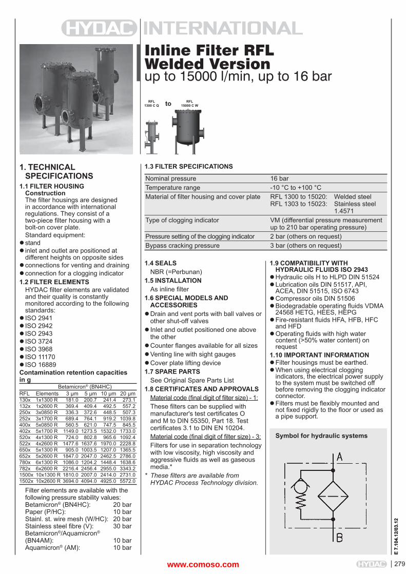
Inline Filter RFLWelded Versionup to 15000 l/min, up to 16 bar
1. TECHNICALSPECIFICATIONS
1.1 FILTER HOUSINGConstructionThe fi lter housings are designed in accordance with international regulations. They consist of a two-piece fi lter housing with a bolt-on cover plate.Standard equipment:
standinlet and outlet are positioned at
different heights on opposite sidesconnections for venting and drainingconnection for a clogging indicator1.2 FILTER ELEMENTS
HYDAC fi lter elements are validated and their quality is constantly monitored according to the following standards:
ISO 2941ISO 2942 ISO 2943 ISO 3724ISO 3968 ISO 11170ISO 16889Contamination retention capacities in g Betamicron® (BN4HC)RFL Elements 3 μm 5 μm 10 μm 20 μm130x 1x1300 R 181.0 200.7 241.4 273.1132x 1x2600 R 369.4 409.4 492.5 557.2250x 3x0850 R 336.3 372.6 448.5 507.3252x 3x1700 R 689.4 764.1 919.2 1039.8400x 5x0850 R 560.5 621.0 747.5 845.5402x 5x1700 R 1149.0 1273.5 1532.0 1733.0520x 4x1300 R 724.0 802.8 965.6 1092.4522x 4x2600 R 1477.6 1637.6 1970.0 2228.8650x 5x1300 R 905.0 1003.5 1207.0 1365.5652x 5x2600 R 1847.0 2047.0 2462.5 2786.0780x 6x1300 R 1086.0 1204.2 1448.4 1638.6782x 6x2600 R 2216.4 2456.4 2955.0 3343.21500x 10x1300 R 1810.0 2007.0 2414.0 2731.01502x 10x2600 R 3694.0 4094.0 4925.0 5572.0
Filter elements are available with the following pressure stability values:Betamicron® (BN4HC): 20 barPaper (P/HC): 10 barStainl. st. wire mesh (W/HC): 20 barStainless steel fi bre (V): 30 barBetamicron®/Aquamicron®
(BN4AM): 10 barAquamicron® (AM): 10 bar
1.4 SEALSNBR (=Perbunan)
1.5 INSTALLATIONAs inline fi lter
1.6 SPECIAL MODELS AND ACCESSORIES
Drain and vent ports with ball valves or other shut-off valves
Inlet and outlet positioned one above the other
Counter fl anges available for all sizesVenting line with sight gaugesCover plate lifting device1.7 SPARE PARTS
See Original Spare Parts List1.8 CERTIFICATES AND APPROVALS
Material code (fi nal digit of fi lter size) - 1:These fi lters can be supplied with manufacturer's test certifi cates O and M to DIN 55350, Part 18. Test certifi cates 3.1 to DIN EN 10204. Material code (fi nal digit of fi lter size) - 3:Filters for use in separation technology with low viscosity, high viscosity and aggressive fl uids as well as gaseous media.*
* These fi lters are available from HYDAC Process Technology division.
1.9 COMPATIBILITY WITH HYDRAULIC FLUIDS ISO 2943
Hydraulic oils H to HLPD DIN 51524Lubrication oils DIN 51517, API,
ACEA, DIN 51515, ISO 6743Compressor oils DIN 51506Biodegradable operating fl uids VDMA
24568 HETG, HEES, HEPGFire-resistant fl uids HFA, HFB, HFC
and HFDOperating fl uids with high water
content (>50% water content) on request
1.10 IMPORTANT INFORMATIONFilter housings must be earthed.When using electrical clogging
indicators, the electrical power supply to the system must be switched off before removing the clogging indicatorconnector.
Filters must be fl exibly mounted and not fi xed rigidly to the fl oor or used as a pipe support.
1.3 FILTER SPECIFICATIONS
Nominal pressure 16 bar Temperature range -10 °C to +100 °C Material of fi lter housing and cover plate RFL 1300 to 15020: Welded steel RFL 1303 to 15023: Stainless steel 1.4571 Type of clogging indicator VM (differential pressure measurement up to 210 bar operating pressure) Pressure setting of the clogging indicator 2 bar (others on request) Bypass cracking pressure 3 bar (others on request)
Symbol for hydraulic systems
E 7.
104.
12/0
3.12
RFL 1300 C Q
RFL 15000 C Wto
www.comoso.com
280
E 7.
104.
12/0
3.12
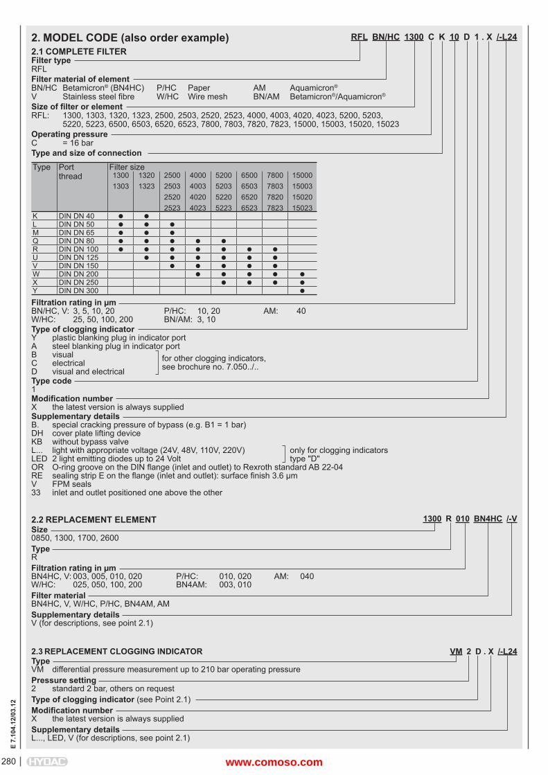
RFL BN/HC 1300 C K 10 D 1 . X /-L24
Filter typeRFLFilter material of elementBN/HC Betamicron® (BN4HC) P/HC Paper AM Aquamicron®
V Stainless steel fi bre W/HC Wire mesh BN/AM Betamicron®/Aquamicron®
Size of fi lter or elementRFL: 1300, 1303, 1320, 1323, 2500, 2503, 2520, 2523, 4000, 4003, 4020, 4023, 5200, 5203, 5220, 5223, 6500, 6503, 6520, 6523, 7800, 7803, 7820, 7823, 15000, 15003, 15020, 15023Operating pressureC = 16 barType and size of connectionType Port
threadFilter size13001303
13201323
2500250325202523
4000400340204023
5200520352205223
6500650365206523
7800780378207823
15000150031502015023
K DIN DN 40 L DIN DN 50 M DIN DN 65 Q DIN DN 80 R DIN DN 100 U DIN DN 125 V DIN DN 150 W DIN DN 200 X DIN DN 250 Y DIN DN 300
Filtration rating in μmBN/HC, V: 3, 5, 10, 20 P/HC: 10, 20 AM: 40W/HC: 25, 50, 100, 200 BN/AM: 3, 10Type of clogging indicatorY plastic blanking plug in indicator portA steel blanking plug in indicator portB visual for other clogging indicators,C electrical see brochure no. 7.050../..D visual and electricalType code1 Modifi cation numberX the latest version is always suppliedSupplementary detailsB. special cracking pressure of bypass (e.g. B1 = 1 bar)DH cover plate lifting deviceKB without bypass valveL... light with appropriate voltage (24V, 48V, 110V, 220V) only for clogging indicatorsLED 2 light emitting diodes up to 24 Volt type "D"OR O-ring groove on the DIN fl ange (inlet and outlet) to Rexroth standard AB 22-04RE sealing strip E on the fl ange (inlet and outlet): surface fi nish 3.6 μmV FPM seals33 inlet and outlet positioned one above the other
2. MODEL CODE (also order example)2.1 COMPLETE FILTER
1300 R 010 BN4HC /-VSize0850, 1300, 1700, 2600TypeRFiltration rating in μmBN4HC, V: 003, 005, 010, 020 P/HC: 010, 020 AM: 040W/HC: 025, 050, 100, 200 BN4AM: 003, 010Filter materialBN4HC, V, W/HC, P/HC, BN4AM, AMSupplementary detailsV (for descriptions, see point 2.1)
2.2 REPLACEMENT ELEMENT
2.3 REPLACEMENT CLOGGING INDICATOR VM 2 D . X /-L24TypeVM differential pressure measurement up to 210 bar operating pressurePressure setting2 standard 2 bar, others on requestType of clogging indicator (see Point 2.1)Modifi cation numberX the latest version is always suppliedSupplementary detailsL..., LED, V (for descriptions, see point 2.1)
www.comoso.com
281
E 7.
104.
12/0
3.12
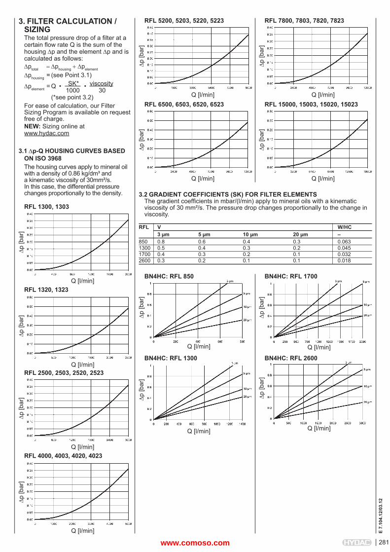
3. FILTER CALCULATION /SIZINGThe total pressure drop of a fi lter at a certain fl ow rate Q is the sum of the housing p and the element p and is calculated as follows:ptotal phousingpelement
phousing = (see Point 3.1)
pelement = Q • SK* • viscosity 1000 30 (*see point 3.2) For ease of calculation, our Filter Sizing Program is available on request free of charge.NEW: Sizing online at www.hydac.com
3.1 p-Q HOUSING CURVES BASED ON ISO 3968The housing curves apply to mineral oil with a density of 0.86 kg/dm³ and a kinematic viscosity of 30mm²/s. In this case, the differential pressure changes proportionally to the density.
RFL 1300, 1303
p [b
ar]
Q [l/min]RFL 1320, 1323
p [b
ar]
Q [l/min]
3.2 GRADIENT COEFFICIENTS (SK) FOR FILTER ELEMENTSThe gradient coeffi cients in mbar/(l/min) apply to mineral oils with a kinematic viscosity of 30 mm²/s. The pressure drop changes proportionally to the change in viscosity.
RFL V W/HC 3 μm 5 μm 10 μm 20 μm –850 0.8 0.6 0.4 0.3 0.0631300 0.5 0.4 0.3 0.2 0.0451700 0.4 0.3 0.2 0.1 0.0322600 0.3 0.2 0.1 0.1 0.018
p [b
ar]
Q [l/min]
BN4HC: RFL 1700
p [b
ar]
Q [l/min]
BN4HC: RFL 850
p [b
ar]
Q [l/min]
BN4HC: RFL 1300
p [b
ar]
Q [l/min]
BN4HC: RFL 2600
RFL 2500, 2503, 2520, 2523
p [b
ar]
Q [l/min]RFL 4000, 4003, 4020, 4023
p [b
ar]
Q [l/min]
RFL 5200, 5203, 5220, 5223
p [b
ar]
Q [l/min]RFL 6500, 6503, 6520, 6523
p [b
ar]
Q [l/min]
RFL 7800, 7803, 7820, 7823
p [b
ar]
Q [l/min]RFL 15000, 15003, 15020, 15023
p [b
ar]
Q [l/min]
www.comoso.com
282
E 7.
104.
12/0
3.12
NOTEThe information in this brochure relates to the operating conditions and applications described.For applications or operating conditions not described, please contact the relevant technical department. Subject to technical modifi cations.
HYDAC FILTERTECHNIK GMBHIndustriegebiet66280 Sulzbach/Saar, GermanyTel.: 0 68 97 / 509-01Fax: 0 68 97 / 509-300Internet: www.hydac.comE-mail: fi [email protected]
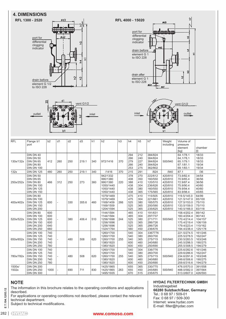
RFL Flange b1 b2 d1 d2 d3 h1 h2 h3 h4 h5 h7 Weight Volume of port including pressure element chamber [kg] [l] DIN DN 40 294 212 384/824 64.1/78.1 18/33 DIN DN 50 266 240 384/824 64,1/78,1 18/33130x/132x DIN DN 65 412 260 250 219.1 340 972/1416 370 279 227 384/824 500/940 65.1/79.1 18/33 DIN DN 80 266 240 384/824 67.1/81.1 19/34 DIN DN 100 253 275 362/802 69.1/83.1 19/34132x DIN DN 125 480 260 250 219.1 340 /1416 370 215 291 /824 /940 87.1 /36 DIN DN 50 942/1332 378 270 222/612 420/810 73,9/82,4 34/54 DIN DN 65 990/1380 408 350 160/550 420/810 70.9/85.4 36/56250x/252x DIN DN 80 466 312 250 273 360 990/1380 220 388 410 120/510 420/810 72.9/87.4 36/56 DIN DN 100 1050/1440 438 304 236/626 420/810 75.9/90.4 40/60 DIN DN 125 1050/1440 438 380 160/550 420/810 79.9/94.4 40/60 DIN DN 150 1050/1440 438 365 175/565 420/810 83.9/98.4 45/65 DIN DN 80 1079/1469 475 410 115/505 420/810 119.5/145.0 64/99 DIN DN 100 1079/1469 475 304 221/661 420/810 121.5/147.0 65/100400x/402x DIN DN 125 600 - 330 355.6 460 1169/1459 266 525 380 185/575 420/810 127.5/153.0 75/110 DIN DN 150 1169/1559 525 365 200/590 420/810 133.5/159.0 75/110 DIN DN 200 1204/1594 525 365 235/625 420/810 140.5/166.0 83/118 DIN DN 80 600 1144/1584 465 410 191/631 158.4/202.4 89/142 DIN DN 100 600 1144/1584 465 304 297/737 160.4/204.4 90/143520x/522x DIN DN 125 600 - 380 406.4 510 1256/1696 244 525 380 271/711 500/940 170.4/214.4 104/157 DIN DN 150 600 1256/1696 525 365 286/726 175.4/219.4 106/159 DIN DN 200 640 1256/1696 525 365 286/726 179.4/223.4 110/162 DIN DN 250 660 1324/1764 560 450 236/676 194.4/238.4 125/178 DIN DN 100 740 1260/1700 540 304 3367776 221.5/274.5 161/246 DIN DN 125 740 1260/1700 540 380 260/700 225.5/278.5 162/247650x/652x DIN DN 150 740 - 480 508 620 1260/1700 255 540 365 275/715 500/940 230.5/283.5 163/248 DIN DN 200 740 1380/1820 600 460 240/680 245.5/298.5 190/275 DIN DN 250 780 1380/1820 600 450 250/690 255.5/308.5 194/279 DIN DN 100 740 1260/1700 540 304 336/776 225.6/282.6 161/246 DIN DN 125 740 1260/1700 540 380 260/700 229.6/286.6 162/247780x/782x DIN DN 150 740 - 480 508 620 1260/1700 255 540 365 275/715 500/940 234.6/291.6 163/248 DIN DN 200 740 1380/1820 600 460 240/680 249.6/306.6 190/275 DIN DN 250 780 1380/1820 600 450 250/690 259.6/316.6 194/2791500x/ DIN DN 200 1425/1865 655 365 330/770 476.0/570.0 391/5581502x DIN DN 250 1000 - 690 711 830 1425/1865 263 655 450 245/685 500/940 488.0/582.0 397/564 DIN DN 300 1495/1935 670 515 235/675 513.0/607.0 426/593
4. DIMENSIONS
port fordifferentialcloggingindicator
RFL 1300 - 2520 RFL 4000 - 15020
drain beforeelement G 1/2to ISO 228
vent G1/2
inletoutlet
port fordifferentialcloggingindicator
drain beforeelement G 1to ISO 228
vent G1/2
outletinlet
drain afterelement G 1to ISO 228
www.comoso.com
283
E 7.
112.
4/03
.12
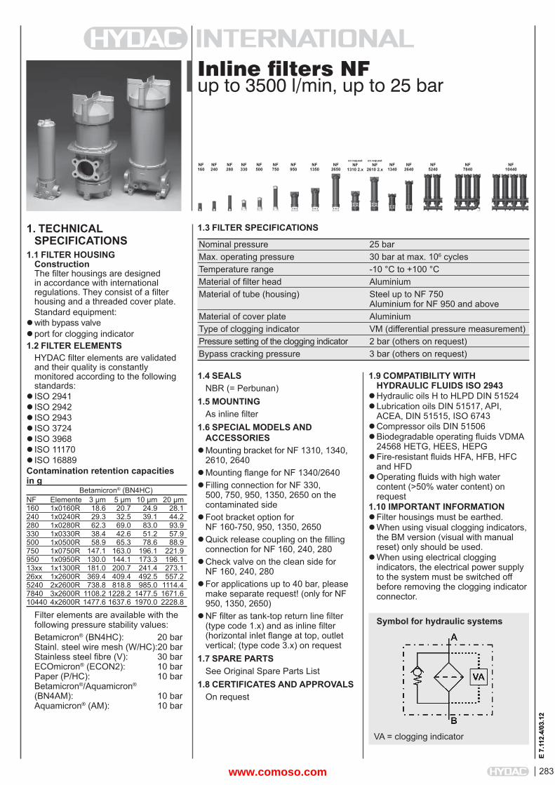
Inline fi lters NFup to 3500 l/min, up to 25 bar
1. TECHNICALSPECIFICATIONS
1.1 FILTER HOUSINGConstructionThe fi lter housings are designed in accordance with international regulations. They consist of a fi lter housing and a threaded cover plate.Standard equipment:
with bypass valveport for clogging indicator1.2 FILTER ELEMENTS
HYDAC fi lter elements are validated and their quality is constantly monitored according to the following standards:
ISO 2941ISO 2942 ISO 2943 ISO 3724ISO 3968 ISO 11170ISO 16889Contamination retention capacities in g Betamicron® (BN4HC)NF Elemente 3 μm 5 μm 10 μm 20 μm160 1x0160R 18.6 20.7 24.9 28.1240 1x0240R 29.3 32.5 39.1 44.2280 1x0280R 62.3 69.0 83.0 93.9330 1x0330R 38.4 42.6 51.2 57.9500 1x0500R 58.9 65.3 78.6 88.9750 1x0750R 147.1 163.0 196.1 221.9950 1x0950R 130.0 144.1 173.3 196.113xx 1x1300R 181.0 200.7 241.4 273.126xx 1x2600R 369.4 409.4 492.5 557.25240 2x2600R 738.8 818.8 985.0 1114.47840 3x2600R 1108.2 1228.2 1477.5 1671.610440 4x2600R 1477.6 1637.6 1970.0 2228.8
Filter elements are available with the following pressure stability values:Betamicron® (BN4HC): 20 barStainl. steel wire mesh (W/HC): 20 barStainless steel fi bre (V): 30 barECOmicron® (ECON2): 10 barPaper (P/HC): 10 barBetamicron®/Aquamicron®
(BN4AM): 10 barAquamicron® (AM): 10 bar
1.4 SEALSNBR (= Perbunan)
1.5 MOUNTINGAs inline fi lter
1.6 SPECIAL MODELS AND ACCESSORIES
Mounting bracket for NF 1310, 1340, 2610, 2640
Mounting fl ange for NF 1340/2640Filling connection for NF 330,
500, 750, 950, 1350, 2650 on the contaminated side
Foot bracket option for NF 160-750, 950, 1350, 2650
Quick release coupling on the fi lling connection for NF 160, 240, 280
Check valve on the clean side for NF 160, 240, 280
For applications up to 40 bar, please make separate request! (only for NF 950, 1350, 2650)
NF fi lter as tank-top return line fi lter (type code 1.x) and as inline fi lter (horizontal inlet fl ange at top, outlet vertical; (type code 3.x) on request
1.7 SPARE PARTSSee Original Spare Parts List
1.8 CERTIFICATES AND APPROVALSOn request
1.9 COMPATIBILITY WITH HYDRAULIC FLUIDS ISO 2943
Hydraulic oils H to HLPD DIN 51524Lubrication oils DIN 51517, API,
ACEA, DIN 51515, ISO 6743Compressor oils DIN 51506Biodegradable operating fl uids VDMA
24568 HETG, HEES, HEPGFire-resistant fl uids HFA, HFB, HFC
and HFDOperating fl uids with high water
content (>50% water content) on request
1.10 IMPORTANT INFORMATIONFilter housings must be earthed.When using visual clogging indicators,
the BM version (visual with manual reset) only should be used.
When using electrical clogging indicators, the electrical power supply to the system must be switched off before removing the clogging indicatorconnector.
1.3 FILTER SPECIFICATIONS
Nominal pressure 25 bar Max. operating pressure 30 bar at max. 106 cycles Temperature range -10 °C to +100 °C Material of fi lter head Aluminium Material of tube (housing) Steel up to NF 750 Aluminium for NF 950 and above Material of cover plate Aluminium Type of clogging indicator VM (differential pressure measurement) Pressure setting of the clogging indicator 2 bar (others on request) Bypass cracking pressure 3 bar (others on request)
Symbol for hydraulic systems
NF160
E 7.
112.
4/03
.12
NF240
NF280
NF330
NF500
NF750
NF950
NF1350
NF2650
NF1340
NF2640
NF5240
NF7840
NF10440
on requestNF
1310 2.x
on requestNF
2610 2.x
VA = clogging indicator
www.comoso.com
E 7.
112.
4/03
.12
284
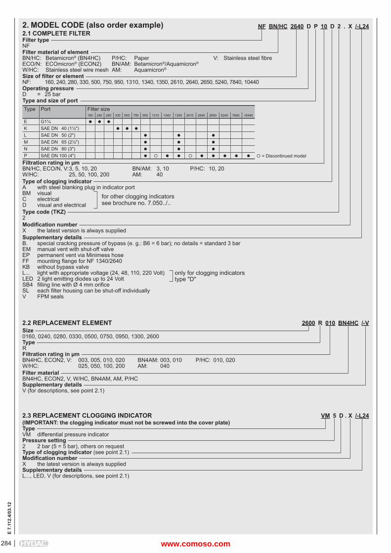
2. MODEL CODE (also order example)2.1 COMPLETE FILTERFilter typeNFFilter material of elementBN/HC: Betamicron® (BN4HC) P/HC: Paper V: Stainless steel fi bre ECO/N: ECOmicron® (ECON2) BN/AM: Betamicron®/Aquamicron®
W/HC: Stainless steel wire mesh AM: Aquamicron®
Size of fi lter or elementNF: 160, 240, 280, 330, 500, 750, 950, 1310, 1340, 1350, 2610, 2640, 2650, 5240, 7840, 10440Operating pressureD = 25 barType and size of portType Port Filter size
160 240 280 330 500 750 950 1310 1340 1350 2610 2640 2650 5240 7840 10440
E G1¼
K SAE DN 40 (1½")
L SAE DN 50 (2")
M SAE DN 65 (2½")
N SAE DN 80 (3")
P SAE DN 100 (4") = Discontinued modelFiltration rating in μmBN/HC, ECO/N, V: 3, 5, 10, 20 BN/AM: 3, 10 P/HC: 10, 20W/HC: 25, 50, 100, 200 AM: 40Type of clogging indicatorA with steel blanking plug in indicator port BM visualC electricalD visual and electricalType code (TKZ)2Modifi cation numberX the latest version is always suppliedSupplementary detailsB. special cracking pressure of bypass (e. g.: B6 = 6 bar); no details = standard 3 barEM manual vent with shut-off valveEP permanent vent via Minimess hoseFF mounting fl ange for NF 1340/2640KB without bypass valveL... light with appropriate voltage (24, 48, 110, 220 Volt)LED 2 light emitting diodes up to 24 VoltSB4 fi lling line with Ø 4 mm orifi ceSL each fi lter housing can be shut-off individuallyV FPM seals
NF BN/HC 2640 D P 10 D 2 . X /-L24
for other clogging indicatorssee brochure no. 7.050../..
only for clogging indicatorstype "D"
2.2 REPLACEMENT ELEMENT 2600 R 010 BN4HC /-VSize0160, 0240, 0280, 0330, 0500, 0750, 0950, 1300, 2600TypeRFiltration rating in μmBN4HC, ECON2, V: 003, 005, 010, 020 BN4AM: 003, 010 P/HC: 010, 020W/HC: 025, 050, 100, 200 AM: 040Filter materialBN4HC, ECON2, V, W/HC, BN4AM, AM, P/HCSupplementary detailsV (for descriptions, see point 2.1)
2.3 REPLACEMENT CLOGGING INDICATOR VM 5 D . X /-L24(IMPORTANT: the clogging indicator must not be screwed into the cover plate)TypeVM differential pressure indicatorPressure setting2 2 bar (5 = 5 bar), others on requestType of clogging indicator (see point 2.1)Modifi cation numberX the latest version is always suppliedSupplementary detailsL..., LED, V (for descriptions, see point 2.1)
www.comoso.com
285
E 7.
112.
4/03
.12
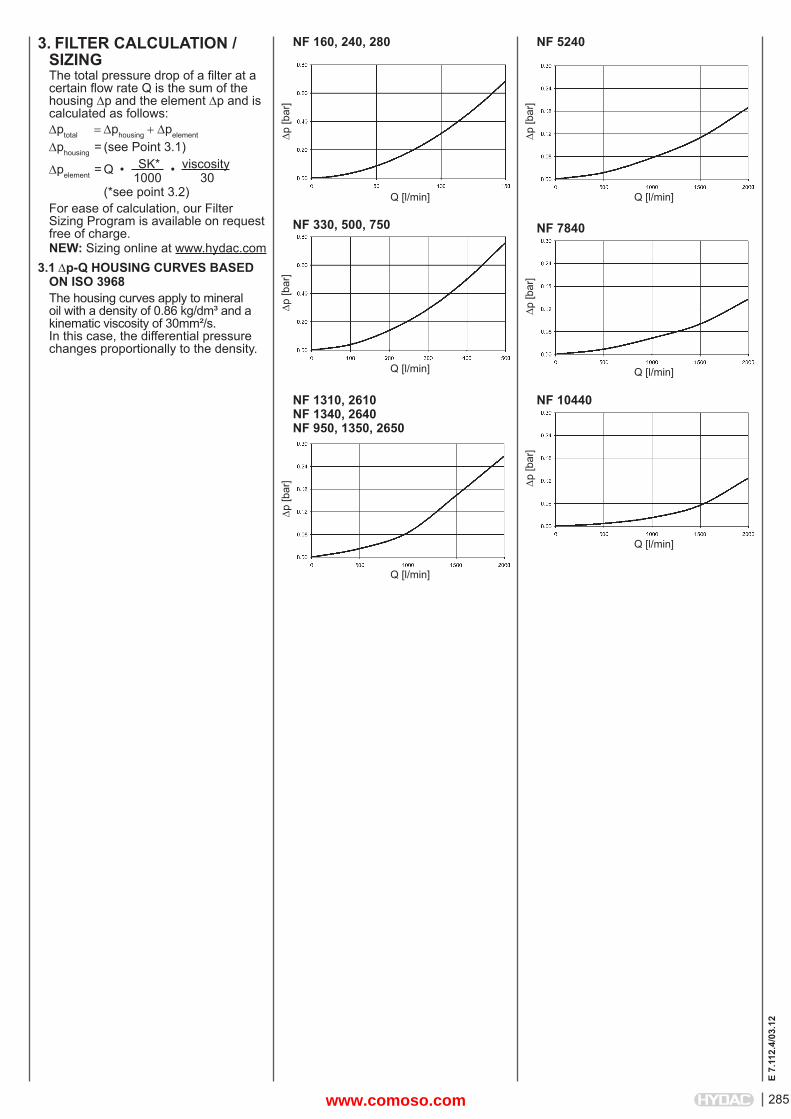
3. FILTER CALCULATION /SIZINGThe total pressure drop of a fi lter at a certain fl ow rate Q is the sum of the housing p and the element p and is calculated as follows:ptotal phousingpelement
phousing = (see Point 3.1)
pelement = Q • SK* • viscosity 1000 30 (*see point 3.2)For ease of calculation, our Filter Sizing Program is available on request free of charge.NEW: Sizing online at www.hydac.com
3.1 p-Q HOUSING CURVES BASED ON ISO 3968The housing curves apply to mineral oil with a density of 0.86 kg/dm³ and a kinematic viscosity of 30mm²/s. In this case, the differential pressure changes proportionally to the density.
NF 160, 240, 280
Q [l/min]
p [b
ar]
NF 330, 500, 750
Q [l/min]
p [b
ar]
NF 5240
Q [l/min]
p [b
ar]
NF 7840
Q [l/min]
p [b
ar]
NF 10440
Q [l/min]p
[bar
]
NF 1310, 2610NF 1340, 2640NF 950, 1350, 2650
Q [l/min]
p [b
ar]
www.comoso.com
E 7.
112.
4/03
.12
286
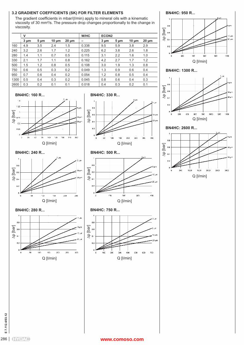
3.2 GRADIENT COEFFICIENTS (SK) FOR FILTER ELEMENTSThe gradient coeffi cients in mbar/(l/min) apply to mineral oils with a kinematic viscosity of 30 mm²/s. The pressure drop changes proportionally to the change in viscosity.
p [b
ar]
Q [l/min]
BN4HC: 160 R...p
[bar
]
Q [l/min]
BN4HC: 330 R...
V W/HC ECON2 3 μm 5 μm 10 μm 20 μm – 3 μm 5 μm 10 μm 20 μm160 4.9 3.5 2.4 1.5 0.338 9.5 5.9 3.8 2.9240 3.2 2.6 1.7 1.2 0.225 6.2 3.8 2.6 1.8280 1.4 1.1 0.7 0.5 0.115 3.1 2.2 1.6 1.0330 2.1 1.7 1.1 0.8 0.162 4.2 2.7 1.7 1.2500 1.5 1.2 0.8 0.5 0.108 3.0 1.9 1.3 0.8750 0.6 0.5 0.3 0.2 0.049 1.3 0.9 0.6 0.4950 0.7 0.6 0.4 0.2 0.054 1.2 0.8 0.5 0.41300 0.5 0.4 0.3 0.2 0.045 0.8 0.6 0.4 0.32600 0.3 0.2 0.1 0.1 0.018 0.4 0.3 0.2 0.1
p [b
ar]
Q [l/min]
BN4HC: 240 R...
p [b
ar]
Q [l/min]
BN4HC: 500 R...
p [b
ar]
Q [l/min]
BN4HC: 280 R...
p [b
ar]
Q [l/min]
BN4HC: 750 R...
p [b
ar]
Q [l/min]
BN4HC: 950 R...
p [b
ar]
Q [l/min]
BN4HC: 1300 R...
p [b
ar]
Q [l/min]
BN4HC: 2600 R...
www.comoso.com
287
E 7.
112.
4/03
.12
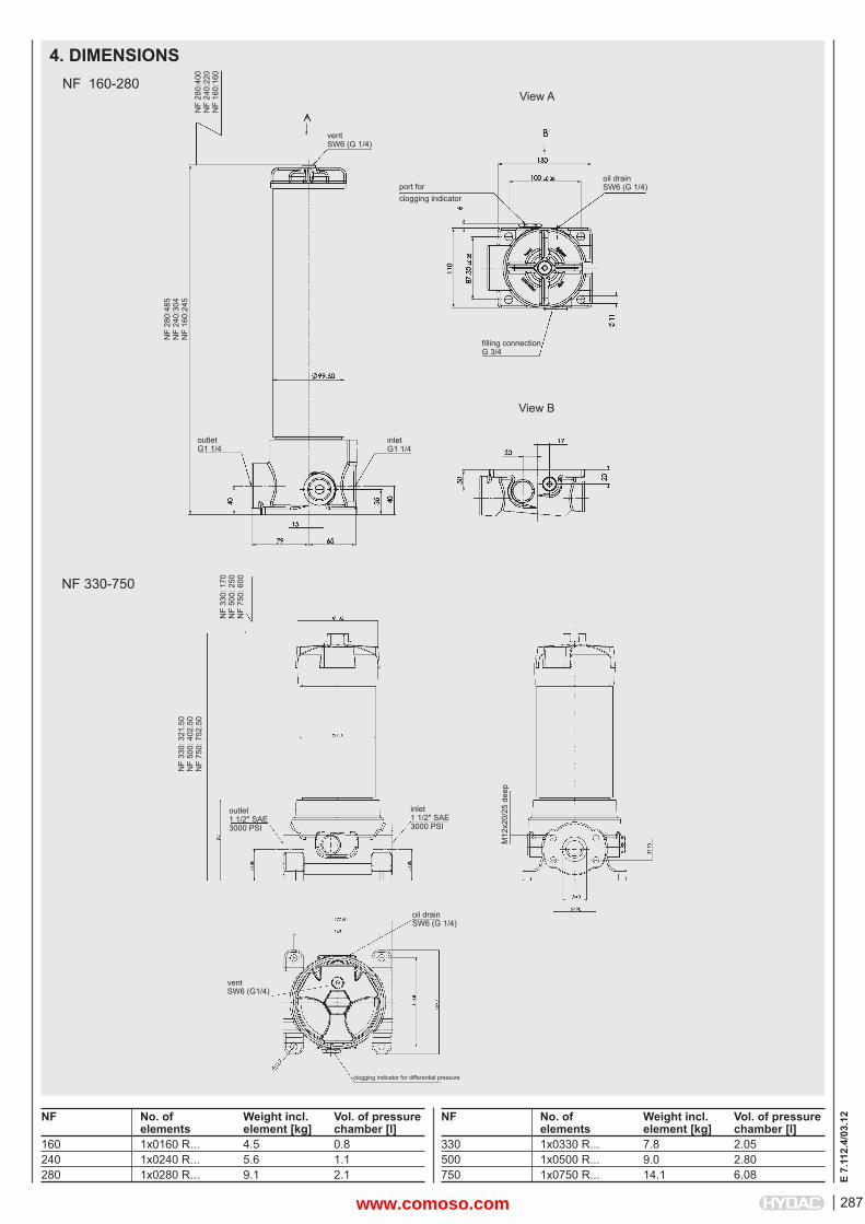
4. DIMENSIONS
ventSW6 (G 1/4)
NF 160-280
NF No. of Weight incl. Vol. of pressure elements element [kg] chamber [l]330 1x0330 R... 7.8 2.05500 1x0500 R... 9.0 2.80750 1x0750 R... 14.1 6.08
NF No. of Weight incl. Vol. of pressure elements element [kg] chamber [l]160 1x0160 R... 4.5 0.8240 1x0240 R... 5.6 1.1280 1x0280 R... 9.1 2.1
NF 330-750
port forclogging indicator
View B
outletG1 1/4
oil drainSW6 (G 1/4)
fi lling connectionG 3/4
View A
NF
280:
400
NF
240:
220
NF
160:
160
NF
280:
485
NF
240:
304
NF
160:
245
inletG1 1/4
NF
330:
170
NF
500:
250
NF
750:
600
NF
330:
321
.50
NF
500:
402
.50
NF
750:
752
.50
outlet1 1/2" SAE3000 PSI
inlet1 1/2" SAE3000 PSI
ventSW6 (G1/4)
oil drainSW6 (G 1/4)
clogging indicator for differential pressure
M12
x20/
25 d
eep
www.comoso.com
E 7.
112.
4/03
.12
288
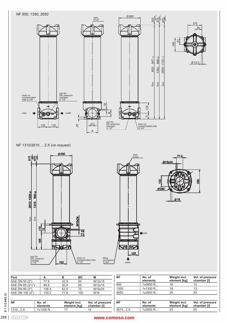
NF 950, 1350, 2650
NF No. of Weight incl. Vol. of pressure elements element [kg] chamber [l]950 1x0950 R... 16 101350 1x1300 R... 18 132650 1x2600 R... 25 25
Port A B ØC MSAE DN 50 (2") 77.8 42.9 50 M12x15SAE DN 65 (2½") 88.9 50.8 65 M12x15SAE DN 80 (3") 106.4 62.9 75 M16x24SAE DN 100 (4") 130.2 77.8 100 M16
inlet outlet
port fordiff. pressure indicatorG 1/2"
port fordiff. pressure indicatorG 1/2"
drain oncontaminated side G 3/4"
drain oncontaminated sideG 3/4"
Siz
e
Siz
e
Siz
e
vent G1/2"
NF 1310/2610 ... 2.X (on request)
drain oncontaminated sideG 1/2"
port fordiff. pressure indicatorG 1/2"
Siz
e
Siz
e
vent G1/2"
inlet
outlet
fi lling connectionG 3/4"
NF No. of Weight incl. Vol. of pressure elements element [kg] chamber [l]1310...2.X 1x1300 R... 17 14
NF No. of Weight incl. Vol. of pressure elements element [kg] chamber [l]2610...2.X 1x2600 R... 23 25
www.comoso.com
289
E 7.
112.
4/03
.12
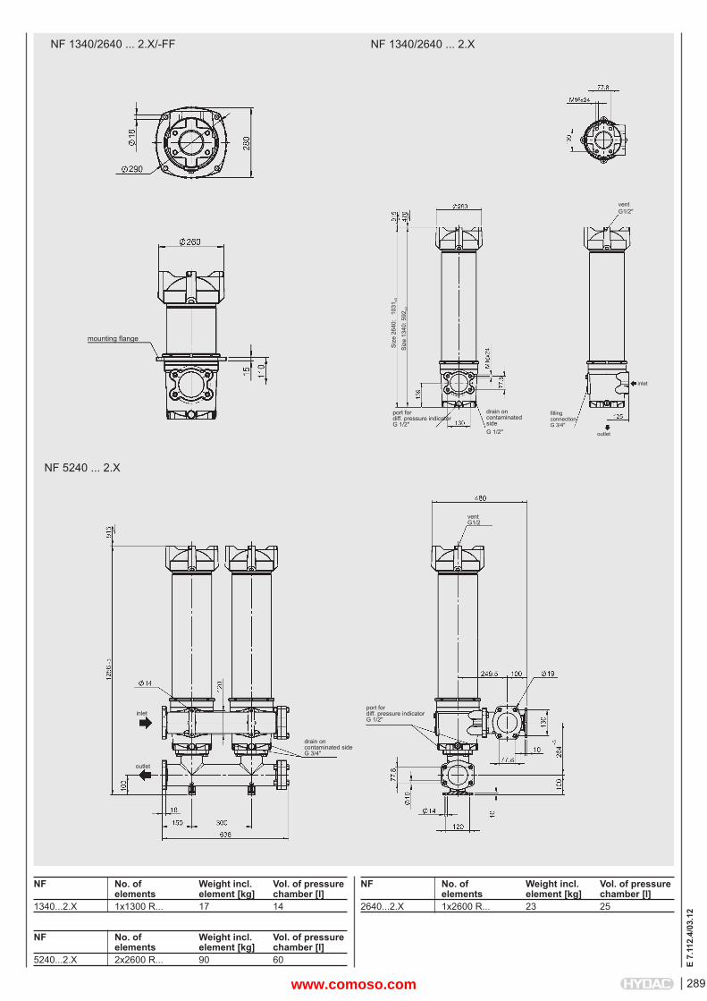
NF No. of Weight incl. Vol. of pressure elements element [kg] chamber [l]2640...2.X 1x2600 R... 23 25
NF No. of Weight incl. Vol. of pressure elements element [kg] chamber [l]1340...2.X 1x1300 R... 17 14
NF 1340/2640 ... 2.X
fi lling connectionG 3/4"
vent G1/2
outlet
outlet
inlet
inlet
NF 1340/2640 ... 2.X/-FF
drain oncontaminated sideG 1/2"
mounting fl ange
Siz
e 26
40:
103
1 ±3
vent G1/2"
port fordiff. pressure indicatorG 1/2"
port fordiff. pressure indicatorG 1/2"
Siz
e 13
40: 5
92±3
NF 5240 ... 2.X
drain oncontaminated sideG 3/4"
NF No. of Weight incl. Vol. of pressure elements element [kg] chamber [l]5240...2.X 2x2600 R... 90 60
www.comoso.com
E 7.
112.
4/03
.12
290
NOTEThe information in this brochure relates to the operating conditions and applications described.For applications or operating conditions not described, please contact the relevant technical department. Subject to technical modifi cations.
HYDAC FILTERTECHNIK GMBHIndustriegebietD-66280 Sulzbach/Saar, GermanyTel.: 0 68 97 / 509-01Fax: 0 68 97 / 509-300Internet: www.hydac.comE-mail: fi [email protected]
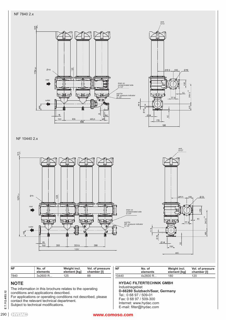
NF 7840 2.x
NF No. of Weight incl. Vol. of pressure elements element [kg] chamber [l]7840 3x2600 R... 125 88
NF No. of Weight incl. Vol. of pressure elements element [kg] chamber [l]10440 4x2600 R... 180 120
vent G1/2
drain oncontaminated sideG 1/2"
inlet
outlet
port fordiff. pressure indicatorG 1/2"
NF 10440 2.x
inlet
outlet
port fordiff. pressure indicatorG 1/2"
drain oncontaminated sideG 3/4"
vent G1/2"
www.comoso.com
291
E 7.
573.
1/03
.12
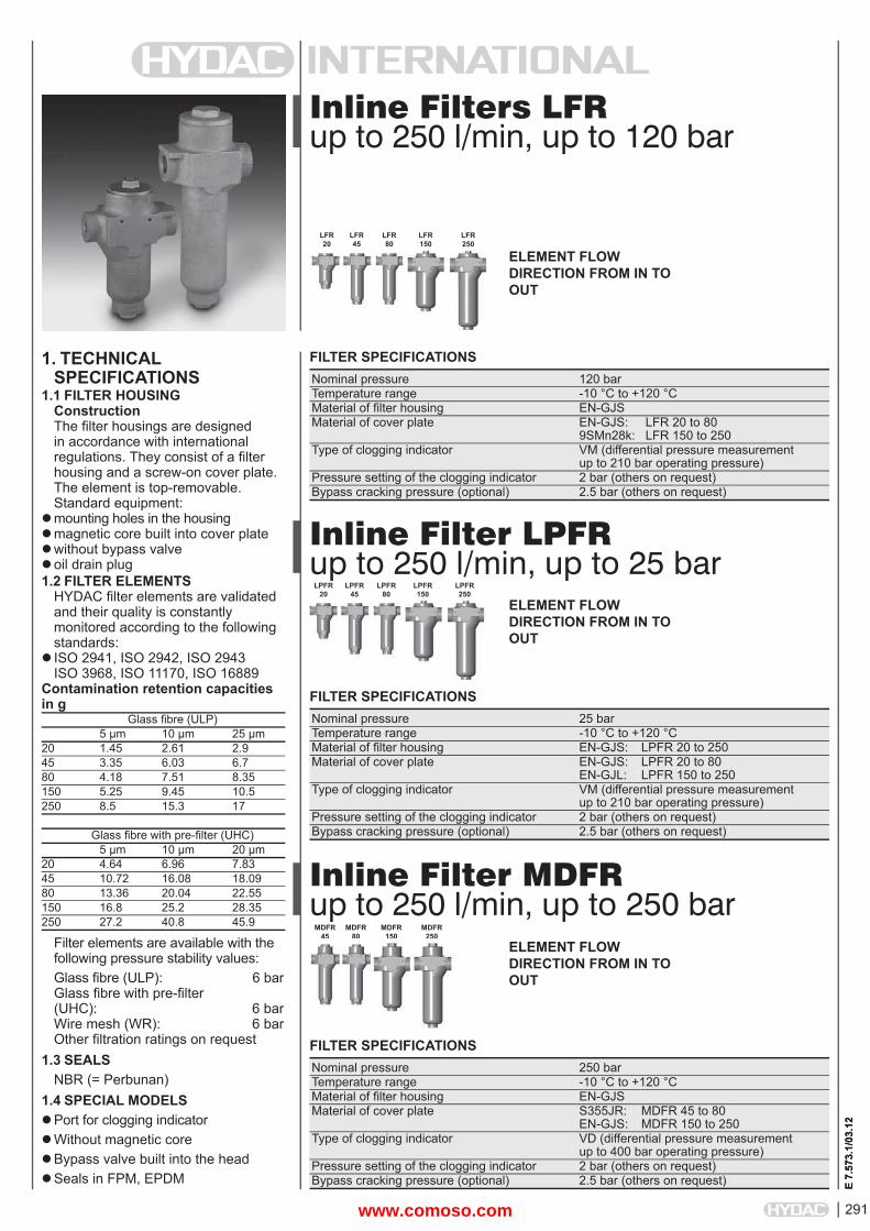
Inline Filters LFRup to 250 l/min, up to 120 bar
1. TECHNICALSPECIFICATIONS
1.1 FILTER HOUSINGConstructionThe fi lter housings are designed in accordance with international regulations. They consist of a fi lter housing and a screw-on cover plate. The element is top-removable.Standard equipment:
mounting holes in the housingmagnetic core built into cover platewithout bypass valveoil drain plug1.2 FILTER ELEMENTS
HYDAC fi lter elements are validated and their quality is constantly monitored according to the following standards:
ISO 2941, ISO 2942, ISO 2943ISO 3968, ISO 11170, ISO 16889
Contamination retention capacities in g Glass fi bre (ULP) 5 μm 10 μm 25 μm20 1.45 2.61 2.945 3.35 6.03 6.780 4.18 7.51 8.35150 5.25 9.45 10.5250 8.5 15.3 17
Glass fi bre with pre-fi lter (UHC) 5 μm 10 μm 20 μm20 4.64 6.96 7.8345 10.72 16.08 18.0980 13.36 20.04 22.55150 16.8 25.2 28.35250 27.2 40.8 45.9
Filter elements are available with the following pressure stability values:Glass fi bre (ULP): 6 barGlass fi bre with pre-fi lter(UHC): 6 barWire mesh (WR): 6 barOther fi ltration ratings on request
1.3 SEALSNBR (= Perbunan)
1.4 SPECIAL MODELSPort for clogging indicatorWithout magnetic coreBypass valve built into the headSeals in FPM, EPDM
FILTER SPECIFICATIONS Nominal pressure 120 bar Temperature range -10 °C to +120 °C Material of fi lter housing EN-GJS Material of cover plate EN-GJS: LFR 20 to 80 9SMn28k: LFR 150 to 250 Type of clogging indicator VM (differential pressure measurement up to 210 bar operating pressure) Pressure setting of the clogging indicator 2 bar (others on request) Bypass cracking pressure (optional) 2.5 bar (others on request)
LFR20
LFR45
LFR80
LFR150
LFR250
Inline Filter LPFRup to 250 l/min, up to 25 bar
FILTER SPECIFICATIONS Nominal pressure 25 bar Temperature range -10 °C to +120 °C Material of fi lter housing EN-GJS: LPFR 20 to 250 Material of cover plate EN-GJS: LPFR 20 to 80 EN-GJL: LPFR 150 to 250 Type of clogging indicator VM (differential pressure measurement up to 210 bar operating pressure) Pressure setting of the clogging indicator 2 bar (others on request) Bypass cracking pressure (optional) 2.5 bar (others on request)
LPFR20
LPFR45
LPFR80
LPFR150
LPFR250
ELEMENT FLOW DIRECTION FROM IN TO OUT
ELEMENT FLOW DIRECTION FROM IN TO OUT
Inline Filter MDFRup to 250 l/min, up to 250 bar
FILTER SPECIFICATIONS Nominal pressure 250 bar Temperature range -10 °C to +120 °C Material of fi lter housing EN-GJS Material of cover plate S355JR: MDFR 45 to 80 EN-GJS: MDFR 150 to 250 Type of clogging indicator VD (differential pressure measurement up to 400 bar operating pressure) Pressure setting of the clogging indicator 2 bar (others on request) Bypass cracking pressure (optional) 2.5 bar (others on request)
MDFR45
MDFR80
MDFR150
MDFR250
ELEMENT FLOW DIRECTION FROM IN TO OUT
E 7.
573.
1/03
.12
45 80 150 250
www.comoso.com
E 7.
573.
1/03
.12
292
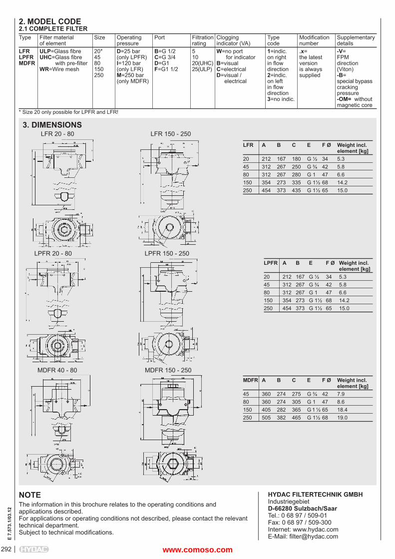
2. MODEL CODE2.1 COMPLETE FILTER
NOTEThe information in this brochure relates to the operating conditions and applications described.For applications or operating conditions not described, please contact the relevant technical department. Subject to technical modifi cations.
HYDAC FILTERTECHNIK GMBHIndustriegebietD-66280 Sulzbach/SaarTel.: 0 68 97 / 509-01Fax: 0 68 97 / 509-300Internet: www.hydac.comE-Mail: fi [email protected]
LFR A B C E F Ø Weight incl. element [kg]20 212 167 180 G ½ 34 5.345 312 267 250 G ¾ 42 5.880 312 267 280 G 1 47 6.6150 354 273 335 G 1½ 68 14.2250 454 373 435 G 1½ 65 15.0
Type Filter material Size Operating Port Filtration Clogging Type Modifi cation Supplementary of element pressure rating indicator (VA) code number detailsLFR ULP=Glass fi bre 20* D=25 bar B=G 1/2 5 W=no port 1=indic. .x= -V=LPFR UHC=Glass fi bre 45 (only LPFR) C=G 3/4 10 for indicator on right the latest FPMMDFR with pre-fi lter 80 I=120 bar D=G1 20(UHC) B=visual in fl ow version direction WR=Wire mesh 150 (only LFR) F=G1 1/2 25(ULP) C=electrical direction is always (Viton) 250 M=250 bar D=visual / 2=indic. supplied -B= (only MDFR) electrical on left special bypass in fl ow cracking direction pressure 3=no indic. -OM= without magnetic core
3. DIMENSIONSLFR 20 - 80 LFR 150 - 250
LPFR 20 - 80LPFR A B E F Ø Weight incl. element [kg]20 212 167 G ½ 34 5.345 312 267 G ¾ 42 5.880 312 267 G 1 47 6.6150 354 273 G 1½ 68 14.2250 454 373 G 1½ 65 15.0
LPFR 150 - 250
MDFR 40 - 80 MDFR 150 - 250MDFR A B C E F Ø Weight incl. element [kg]45 360 274 275 G ¾ 42 7.980 360 274 305 G 1 47 8.6150 405 282 365 G 1 ½ 65 18.4250 505 382 465 G 1½ 68 19.0
* Size 20 only possible for LPFR and LFR!
www.comoso.com
293
E 7.
562.
3/03
.12
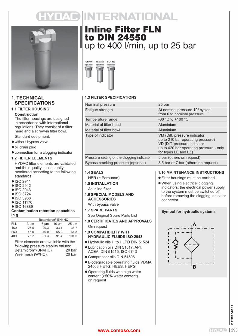
Inline Filter FLN to DIN 24550up to 400 l/min, up to 25 bar
1. TECHNICALSPECIFICATIONS
1.1 FILTER HOUSINGConstructionThe fi lter housings are designed in accordance with international regulations. They consist of a fi lter head and a screw-in fi lter bowl.Standard equipment:
without bypass valveoil drain plugconnection for a clogging indicator1.2 FILTER ELEMENTS
HYDAC fi lter elements are validated and their quality is constantly monitored according to the following standards:
ISO 2941ISO 2942ISO 2943ISO 3724ISO 3968ISO 11170ISO 16889Contamination retention capacities in g Betamicron® BN4HCFLN 3 μm 6 μm 10 μm 25 μm160 27.5 29.3 33.1 36.7250 46.0 49.0 55.2 61.3400 76.2 81.3 91.4 101.5
Filter elements are available with the following pressure stability values:Betamicron® (BN4HC): 20 barWire mesh (W/HC): 20 bar
1.4 SEALSNBR (= Perbunan)
1.5 INSTALLATIONAs inline fi lter
1.6 SPECIAL MODELS AND ACCESSORIESWith bypass valve
1.7 SPARE PARTSSee Original Spare Parts List
1.8 CERTIFICATES AND APPROVALSOn request
1.9 COMPATIBILITY WITH HYDRAULIC FLUIDS ISO 2943
Hydraulic oils H to HLPD DIN 51524Lubrication oils DIN 51517, API,
ACEA, DIN 51515, ISO 6743Compressor oils DIN 51506Biodegradable operating fl uids VDMA
24568 HETG, HEES, HEPGOperating fl uids with high water
content (>50% water content) on request
1.10 MAINTENANCE INSTRUCTIONS Filter housings must be earthed.When using electrical clogging
indicators, the electrical power supply to the system must be switched off before removing the clogging indicator connector.
1.3 FILTER SPECIFICATIONS
Nominal pressure 25 bar Fatigue strength At nominal pressure 106 cycles from 0 to nominal pressure Temperature range -30 °C to +100 °C Material of fi lter head Aluminium Material of fi lter bowl Aluminium Type of indicator VM (Diff. pressure indicator up to 210 bar operating pressure) VD (Diff. pressure indicator up to 420 bar operating pressure - only for types LE and LZ) Pressure setting of the clogging indicator 5 bar (others on request) Bypass cracking pressure (optional) 3.5 bar or 7 bar (others on request)
Symbol for hydraulic systems
FLN 160 FLN 250 FLN 400
E 7.
562.
3/03
.12
www.comoso.com
294
E 7.
562.
3/03
.12
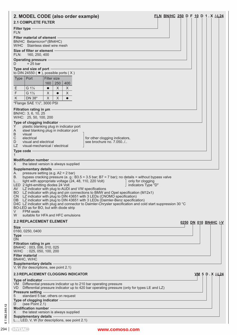
FLN BN/HC 250 D F 10 D 1 . X /-L24
Filter typeFLNFilter material of elementBN/HC Betamicron® (BN4HC)W/HC Stainless steel wire meshSize of fi lter or elementFLN: 160, 250, 400Operating pressureD = 25 barType and size of portto DIN 24550 ( ), possible ports ( X )Type Port Filter size
160 250 400E G 1¼ X XF G 1½ X XK DN 38* X X
*Flange SAE 1½", 3000 PSI
Filtration rating in μmBN/HC: 3, 6, 10, 25W/HC: 25, 50, 100, 200Type of clogging indicatorY plastic blanking plug in indicator portA steel blanking plug in indicator portB visual C electrical for other clogging indicators,D visual and electrical see brochure no. 7.050../..LZ visual-mechanical / electricalType code1 Modifi cation numberX the latest version is always suppliedSupplementary detailsA. pressure setting (e.g. A2 = 2 bar)B. bypass cracking pressure (e. g.: B3.5 = 3.5 bar; B7 = 7 bar); no details = without bypass valveL... light with appropriate voltage (24, 48, 110, 220 Volt) only for clogging LED 2 light-emitting diodes 24 Volt indicators Type "D"AV LZ indicator with plug to AUDI and VW specifi cationsBO LZ indicator with plug and pin connections to BMW and Opel specifi cation (M12x1)CN LZ indicator with plug to DIN 43651 with 3 LEDs (CNOMO specifi cation)DB LZ indicator with plug to DIN 43651 with 3 LEDs (Daimler-Benz specifi cation)D4C LZ indicator with plug and connector to Daimler-Chrysler specifi cation and cold start suppression 30 °CBO-LED as for BO, but with diode stripV FPM sealsW suitable for HFA and HFC emulsions
2. MODEL CODE (also order example)2.1 COMPLETE FILTER
0250 DN 010 BN4HC /-VSize0160, 0250, 0400TypeDNFiltration rating in μmBN4HC : 003, 006, 010, 025W/HC : 025, 050, 100, 200Filter materialBN4HC, W/HCSupplementary detailsV, W (for descriptions, see point 2.1)
2.2 REPLACEMENT ELEMENT
2.3 REPLACEMENT CLOGGING INDICATOR VM 5 D . X /-L24Type of indicatorVM Differential pressure indicator up to 210 bar operating pressureVD Differential pressure indicator up to 420 bar operating pressure (only for types LE and LZ)Pressure setting5 standard 5 bar, others on requestType of clogging indicatorD (see Point 2.1)Modifi cation numberX the latest version is always suppliedSupplementary detailsL..., LED, V, W (for descriptions, see point 2.1)
www.comoso.com
295
E 7.
562.
3/03
.12
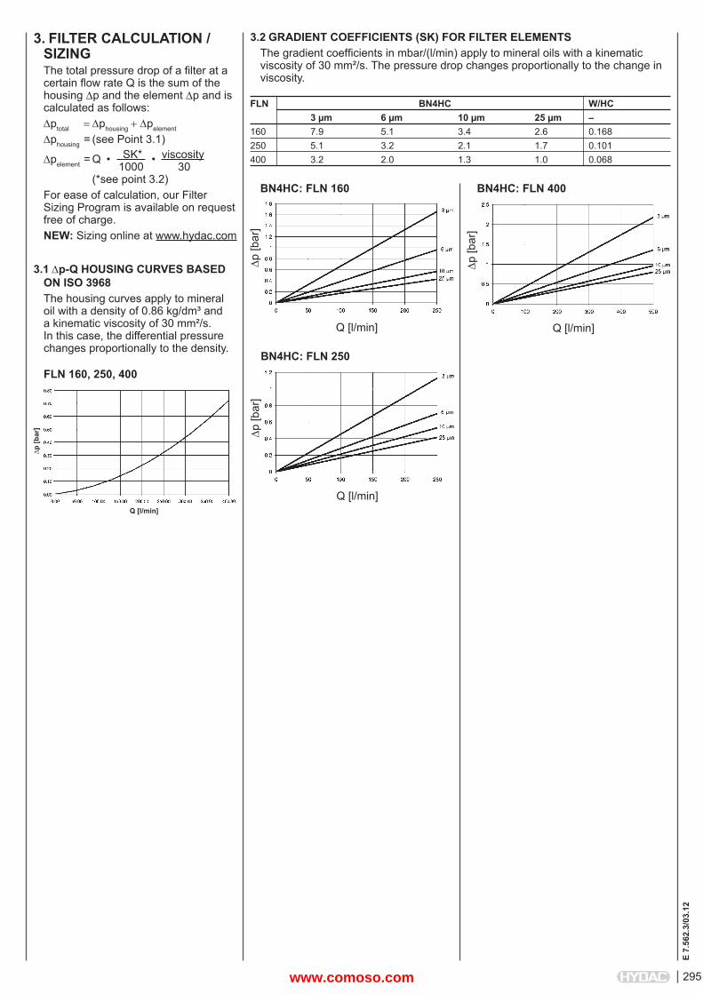
3. FILTER CALCULATION /SIZINGThe total pressure drop of a fi lter at a certain fl ow rate Q is the sum of the housing p and the element p and is calculated as follows:ptotal phousingpelement
phousing = (see Point 3.1)
pelement = Q • SK* • viscosity 1000 30 (*see point 3.2) For ease of calculation, our Filter Sizing Program is available on request free of charge.NEW: Sizing online at www.hydac.com
3.1 p-Q HOUSING CURVES BASED ON ISO 3968The housing curves apply to mineral oil with a density of 0.86 kg/dm³ and a kinematic viscosity of 30 mm²/s. In this case, the differential pressure changes proportionally to the density.
3.2 GRADIENT COEFFICIENTS (SK) FOR FILTER ELEMENTSThe gradient coeffi cients in mbar/(l/min) apply to mineral oils with a kinematic viscosity of 30 mm²/s. The pressure drop changes proportionally to the change in viscosity.
FLN 160, 250, 400
FLN BN4HC W/HC 3 μm 6 μm 10 μm 25 μm –160 7.9 5.1 3.4 2.6 0.168250 5.1 3.2 2.1 1.7 0.101400 3.2 2.0 1.3 1.0 0.068
p [b
ar]
Q [l/min]
BN4HC: FLN 160
p [b
ar]
Q [l/min]
BN4HC: FLN 400
p [b
ar]
Q [l/min]
p [b
ar]
Q [l/min]
BN4HC: FLN 250
www.comoso.com
296
E 7.
562.
3/03
.12
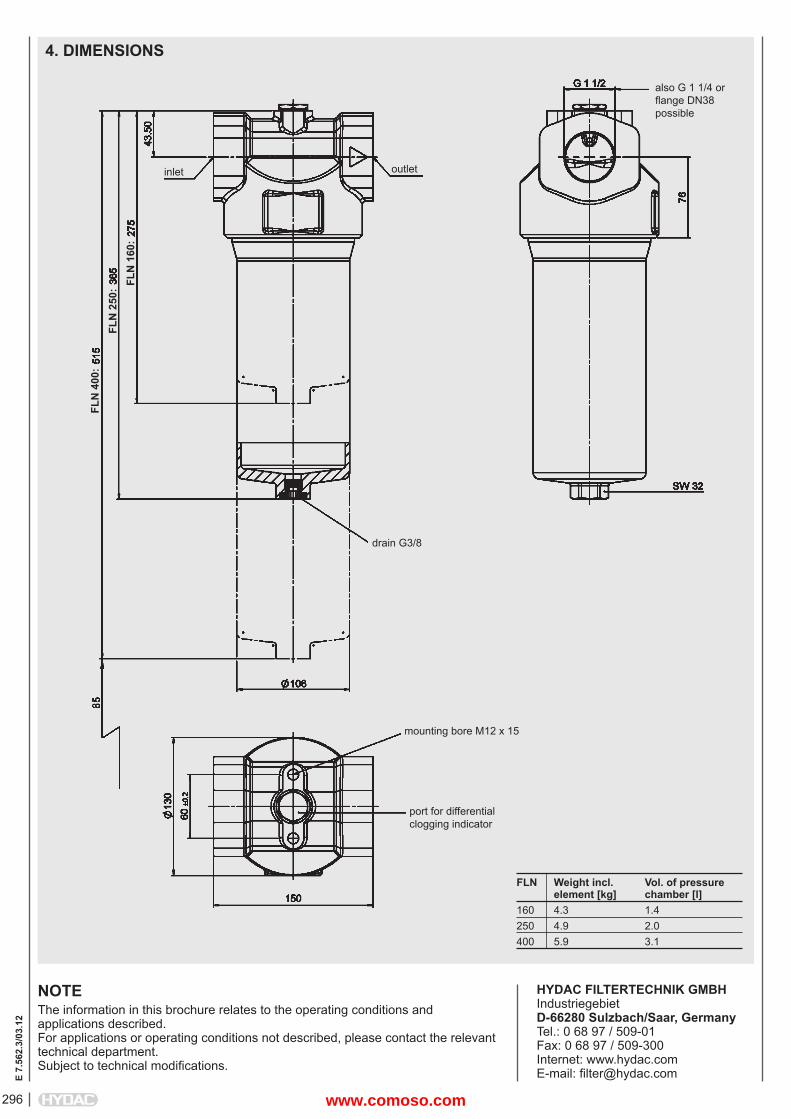
4. DIMENSIONS
NOTEThe information in this brochure relates to the operating conditions and applications described.For applications or operating conditions not described, please contact the relevant technical department. Subject to technical modifi cations.
HYDAC FILTERTECHNIK GMBHIndustriegebietD-66280 Sulzbach/Saar, GermanyTel.: 0 68 97 / 509-01Fax: 0 68 97 / 509-300Internet: www.hydac.comE-mail: fi [email protected]
FLN Weight incl. Vol. of pressure element [kg] chamber [l]160 4.3 1.4250 4.9 2.0400 5.9 3.1
also G 1 1/4 or fl ange DN38 possible
port for differentialclogging indicator
FLN
400
:FL
N 2
50:
mounting bore M12 x 15
FLN
160
:
inlet outlet
drain G3/8
www.comoso.com
297
E 7.
572.
1/03
.12
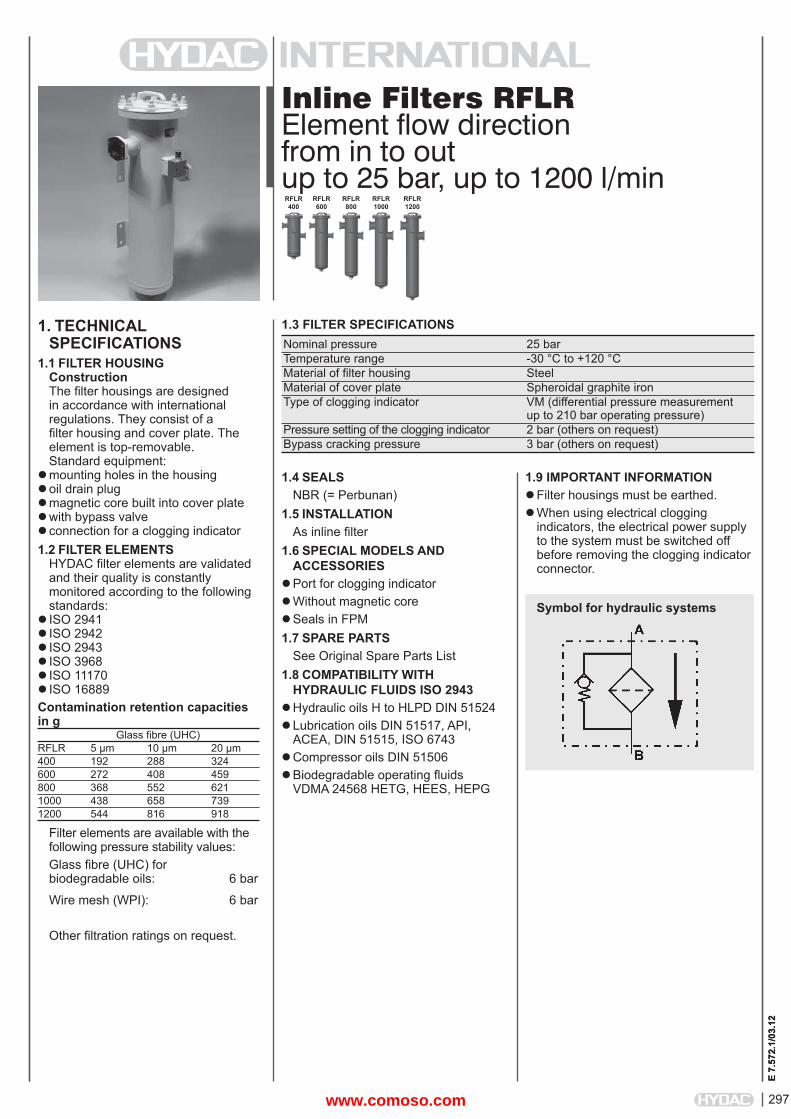
Inline Filters RFLRElement fl ow directionfrom in to outup to 25 bar, up to 1200 l/min
1. TECHNICALSPECIFICATIONS
1.1 FILTER HOUSINGConstructionThe fi lter housings are designed in accordance with international regulations. They consist of a fi lter housing and cover plate. The element is top-removable.Standard equipment:
mounting holes in the housing oil drain plugmagnetic core built into cover plate with bypass valve connection for a clogging indicator 1.2 FILTER ELEMENTS
HYDAC fi lter elements are validated and their quality is constantly monitored according to the following standards:
ISO 2941ISO 2942ISO 2943ISO 3968ISO 11170ISO 16889Contamination retention capacities in g Glass fi bre (UHC)RFLR 5 μm 10 μm 20 μm400 192 288 324600 272 408 459800 368 552 6211000 438 658 7391200 544 816 918
Filter elements are available with the following pressure stability values:Glass fi bre (UHC) forbiodegradable oils: 6 bar
Wire mesh (WPI): 6 bar
Other fi ltration ratings on request.
1.3 FILTER SPECIFICATIONS Nominal pressure 25 bar Temperature range -30 °C to +120 °C Material of fi lter housing Steel Material of cover plate Spheroidal graphite iron Type of clogging indicator VM (differential pressure measurement up to 210 bar operating pressure) Pressure setting of the clogging indicator 2 bar (others on request) Bypass cracking pressure 3 bar (others on request)
RFLR400
RFLR600
RFLR800
RFLR1000
E 7.
572.
1/03
.12
Symbol for hydraulic systems
1.4 SEALSNBR (= Perbunan)
1.5 INSTALLATIONAs inline fi lter
1.6 SPECIAL MODELS AND ACCESSORIES
Port for clogging indicatorWithout magnetic coreSeals in FPM1.7 SPARE PARTS
See Original Spare Parts List1.8 COMPATIBILITY WITH
HYDRAULIC FLUIDS ISO 2943Hydraulic oils H to HLPD DIN 51524Lubrication oils DIN 51517, API,
ACEA, DIN 51515, ISO 6743Compressor oils DIN 51506Biodegradable operating fl uids
VDMA 24568 HETG, HEES, HEPG
RFLR1200
1.9 IMPORTANT INFORMATION Filter housings must be earthed.When using electrical clogging
indicators, the electrical power supply to the system must be switched off before removing the clogging indicator connector.
www.comoso.com
E 7.
572.
1/03
.12
298
RFLR UHC 800 D M 10 W 1.0 /-V
Filter typeRFLRFilter material of elementUHC Glass fi bre for biodegradable operating fl uids WPI Wire meshSize of fi lter or elementRFLR: 400, 600, 800, 1000, 1200Operating pressureD = 25 barType and size of connectionType Connection Filter size
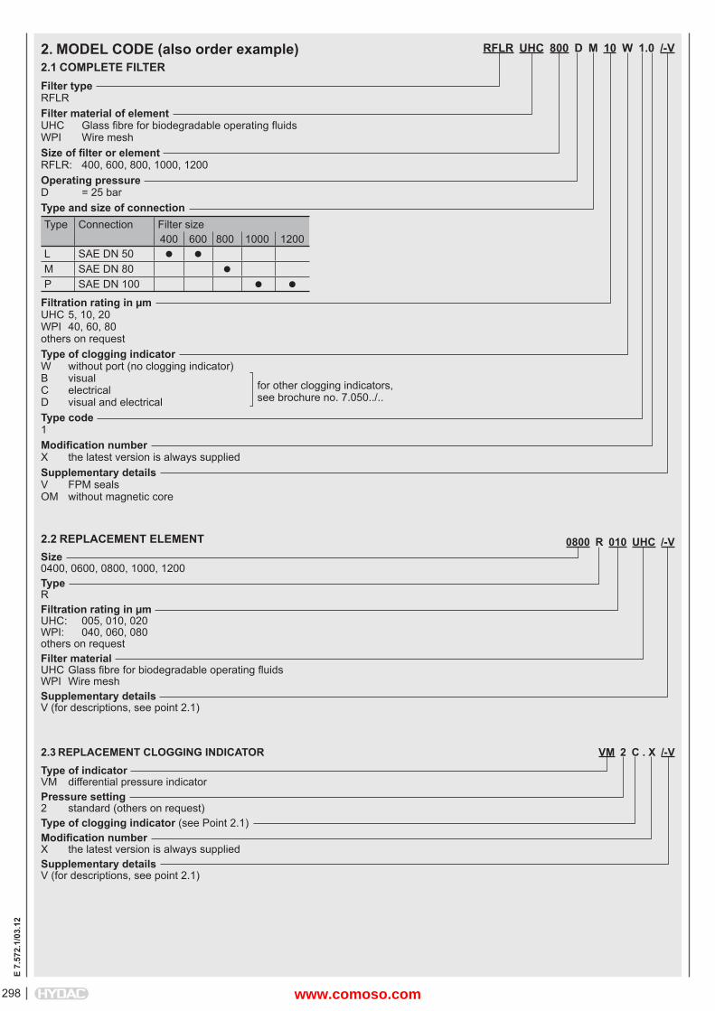
400 600 800 1000 1200L SAE DN 50 M SAE DN 80 P SAE DN 100
Filtration rating in μmUHC 5, 10, 20WPI 40, 60, 80others on requestType of clogging indicatorW without port (no clogging indicator)B visualC electrical for other clogging indicators,D visual and electrical see brochure no. 7.050../..
Type code1 Modifi cation numberX the latest version is always suppliedSupplementary detailsV FPM sealsOM without magnetic core
2. MODEL CODE (also order example)2.1 COMPLETE FILTER
0800 R 010 UHC /-VSize0400, 0600, 0800, 1000, 1200TypeRFiltration rating in μmUHC: 005, 010, 020WPI: 040, 060, 080others on requestFilter materialUHC Glass fi bre for biodegradable operating fl uids WPI Wire meshSupplementary detailsV (for descriptions, see point 2.1)
2.2 REPLACEMENT ELEMENT
2.3 REPLACEMENT CLOGGING INDICATOR VM 2 C . X /-VType of indicatorVM differential pressure indicator Pressure setting2 standard (others on request)Type of clogging indicator (see Point 2.1)Modifi cation numberX the latest version is always suppliedSupplementary detailsV (for descriptions, see point 2.1)
www.comoso.com
299
E 7.
572.
1/03
.12
3. FILTER CALCULATION /SIZING
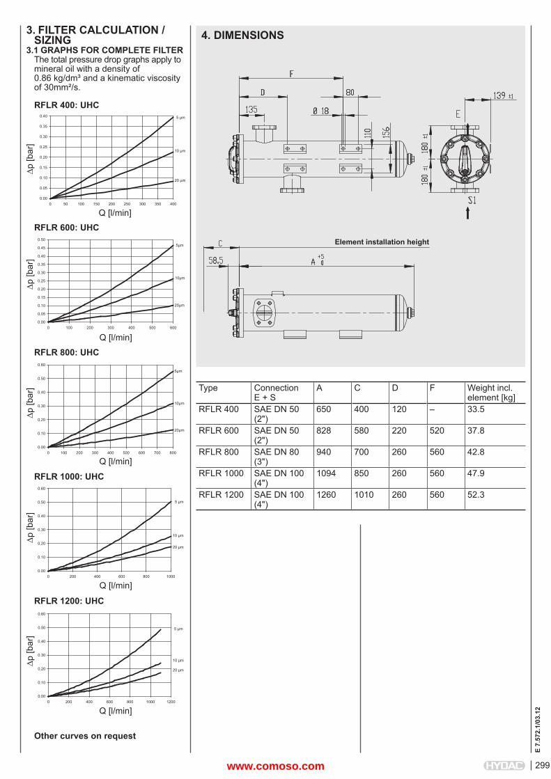
3.1 GRAPHS FOR COMPLETE FILTERThe total pressure drop graphs apply to mineral oil with a density of 0.86 kg/dm³ and a kinematic viscosity of 30mm²/s.
RFLR 400: UHC
p [b
ar]
Q [l/min]
RFLR 600: UHC
p [b
ar]
Q [l/min]
RFLR 800: UHC
p [b
ar]
Q [l/min]
RFLR 1000: UHC
p [b
ar]
Q [l/min]
RFLR 1200: UHC
p [b
ar]
Q [l/min]
4. DIMENSIONS
0.00
0.05
0.10
0.15
0.20
0.25
0.30
0.35
0.40
0 50 100 150 200 250 300 350 400
20 μm
5 μm
10 μm
5μm
20μm
10μm
0.00
0.05
0.10
0.15
0.20
0.25
0.30
0.35
0.40
0.45
0.50
0 100 200 300 400 500 600
5μm
10μm
20μm
0.00
0.10
0.20
0.30
0.40
0.50
0.60
0 100 200 300 400 500 600 700 800
0.00
0.10
0.20
0.30
0.40
0.50
0.60
0 200 400 600 800 1000
5 μm
10 μm
20 μm
0.00
0.10
0.20
0.30
0.40
0.50
0.60
0 200 400 600 800 1000 1200
5 μm
10 μm
20 μm
139 ±1
180
±1180
±1
E
S1
156
110
Ø 18
80
F
D
135
58.5
C
A 0+5
Element installation height
Type ConnectionE + S
A C D F Weight incl.element [kg]
RFLR 400 SAE DN 50(2")
650 400 120 – 33.5
RFLR 600 SAE DN 50(2")
828 580 220 520 37.8
RFLR 800 SAE DN 80(3")
940 700 260 560 42.8
RFLR 1000 SAE DN 100(4")
1094 850 260 560 47.9
RFLR 1200 SAE DN 100(4")
1260 1010 260 560 52.3
Other curves on request
www.comoso.com
E 7.
572.
1/03
.12
300
NOTEThe information in this brochure relates to the operating conditions and applications described.For applications and operating conditions not described, please contact the relevant technical department. Subject to technical modifi cations.
HYDAC FILTERTECHNIK GMBHIndustriegebietD-66280 Sulzbach/Saar, GermanyTel.: 0 68 97 / 509-01Fax: 0 68 97 / 509-300Internet: www.hydac.comE-mail: fi [email protected]
NOTES
www.comoso.com
301
E 7.
118.
3/03
.12
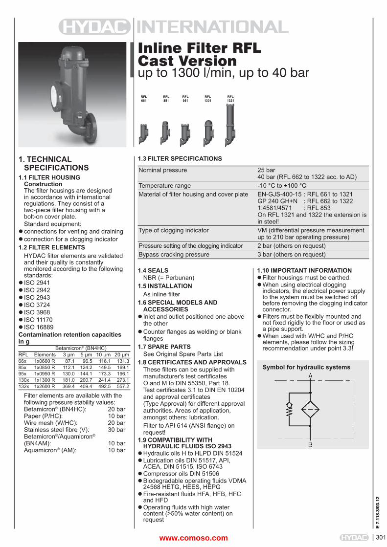
Inline Filter RFLCast Versionup to 1300 l/min, up to 40 bar
1. TECHNICALSPECIFICATIONS
1.1 FILTER HOUSINGConstructionThe fi lter housings are designed in accordance with international regulations. They consist of a two-piece fi lter housing with a bolt-on cover plate.Standard equipment:
connections for venting and drainingconnection for a clogging indicator1.2 FILTER ELEMENTS
HYDAC fi lter elements are validated and their quality is constantly monitored according to the following standards:
ISO 2941ISO 2942 ISO 2943 ISO 3724ISO 3968 ISO 11170ISO 16889Contamination retention capacities in g Betamicron® (BN4HC)RFL Elements 3 μm 5 μm 10 μm 20 μm66x 1x0660 R 87.1 96.5 116.1 131.385x 1x0850 R 112.1 124.2 149.5 169.195x 1x0950 R 130.0 144.1 173.3 196.1130x 1x1300 R 181.0 200.7 241.4 273.1132x 1x2600 R 369.4 409.4 492.5 557.2
Filter elements are available with the following pressure stability values:Betamicron® (BN4HC): 20 barPaper (P/HC): 10 barWire mesh (W/HC): 20 barStainless steel fi bre (V): 30 barBetamicron®/Aquamicron®
(BN4AM): 10 barAquamicron® (AM): 10 bar
1.4 SEALSNBR (= Perbunan)
1.5 INSTALLATIONAs inline fi lter
1.6 SPECIAL MODELS AND ACCESSORIES
Inlet and outlet positioned one above the other
Counter fl anges as welding or blank fl anges
1.7 SPARE PARTSSee Original Spare Parts List
1.8 CERTIFICATES AND APPROVALSThese fi lters can be supplied with manufacturer's test certifi cates O and M to DIN 55350, Part 18. Test certifi cates 3.1 to DIN EN 10204 and approval certifi cates (Type Approval) for different approval authorities. Areas of application, amongst others: lubrication.Filter to API 614 (ANSI fl ange) on request!
1.9 COMPATIBILITY WITH HYDRAULIC FLUIDS ISO 2943
Hydraulic oils H to HLPD DIN 51524Lubrication oils DIN 51517, API,
ACEA, DIN 51515, ISO 6743Compressor oils DIN 51506Biodegradable operating fl uids VDMA
24568 HETG, HEES, HEPGFire-resistant fl uids HFA, HFB, HFC
and HFDOperating fl uids with high water
content (>50% water content) on request
1.10 IMPORTANT INFORMATIONFilter housings must be earthed.When using electrical clogging
indicators, the electrical power supply to the system must be switched off before removing the clogging indicatorconnector.
Filters must be fl exibly mounted and not fi xed rigidly to the fl oor or used as a pipe support.
When used with W/HC and P/HC elements, please follow the sizing recommendation under point 3.3!
1.3 FILTER SPECIFICATIONS
Nominal pressure 25 bar 40 bar (RFL 662 to 1322 acc. to AD) Temperature range -10 °C to +100 °C Material of fi lter housing and cover plate EN-GJS-400-15 : RFL 661 to 1321 GP 240 GH+N : RFL 662 to 1322 1.4581/4571 : RFL 853 On RFL 1321 and 1322 the extension is in steel! Type of clogging indicator VM (differential pressure measurement up to 210 bar operating pressure) Pressure setting of the clogging indicator 2 bar (others on request) Bypass cracking pressure 3 bar (others on request)
Symbol for hydraulic systemsE
7.11
8.3/
03.1
2
RFL 661
RFL 851
RFL 951
RFL 1301
RFL 1321
www.comoso.com
302
E 7.
118.
3/03
.12
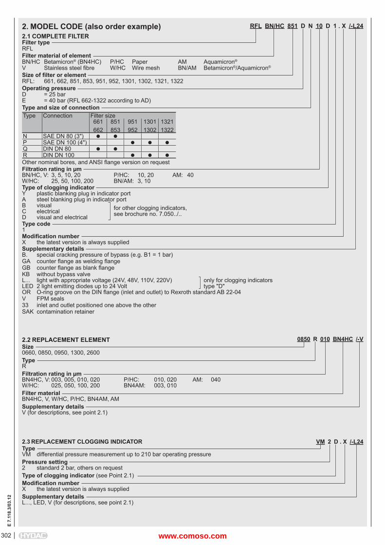
RFL BN/HC 851 D N 10 D 1 . X /-L24
Filter typeRFLFilter material of elementBN/HC Betamicron® (BN4HC) P/HC Paper AM Aquamicron®
V Stainless steel fi bre W/HC Wire mesh BN/AM Betamicron®/Aquamicron®
Size of fi lter or elementRFL: 661, 662, 851, 853, 951, 952, 1301, 1302, 1321, 1322Operating pressureD = 25 barE = 40 bar (RFL 662-1322 according to AD)Type and size of connectionType Connection Filter size
661662
851853
951952
13011302
13211322
N SAE DN 80 (3") P SAE DN 100 (4") Q DIN DN 80 R DIN DN 100 Other nominal bores, and ANSI fl ange version on requestFiltration rating in μmBN/HC, V: 3, 5, 10, 20 P/HC: 10, 20 AM: 40W/HC: 25, 50, 100, 200 BN/AM: 3, 10Type of clogging indicatorY plastic blanking plug in indicator portA steel blanking plug in indicator portB visual for other clogging indicators,C electrical see brochure no. 7.050../..D visual and electricalType code1 Modifi cation numberX the latest version is always suppliedSupplementary detailsB. special cracking pressure of bypass (e.g. B1 = 1 bar)GA counter fl ange as welding fl angeGB counter fl ange as blank fl angeKB without bypass valveL... light with appropriate voltage (24V, 48V, 110V, 220V) only for clogging indicatorsLED 2 light emitting diodes up to 24 Volt type "D"OR O-ring groove on the DIN fl ange (inlet and outlet) to Rexroth standard AB 22-04V FPM seals33 inlet and outlet positioned one above the otherSAK contamination retainer
2. MODEL CODE (also order example)2.1 COMPLETE FILTER
0850 R 010 BN4HC /-VSize0660, 0850, 0950, 1300, 2600TypeRFiltration rating in μmBN4HC, V: 003, 005, 010, 020 P/HC: 010, 020 AM: 040W/HC: 025, 050, 100, 200 BN4AM: 003, 010Filter materialBN4HC, V, W/HC, P/HC, BN4AM, AMSupplementary detailsV (for descriptions, see point 2.1)
2.2 REPLACEMENT ELEMENT
2.3 REPLACEMENT CLOGGING INDICATOR VM 2 D . X /-L24TypeVM differential pressure measurement up to 210 bar operating pressurePressure setting2 standard 2 bar, others on requestType of clogging indicator (see Point 2.1)Modifi cation numberX the latest version is always suppliedSupplementary detailsL..., LED, V (for descriptions, see point 2.1)
www.comoso.com
303
E 7.
118.
3/03
.12
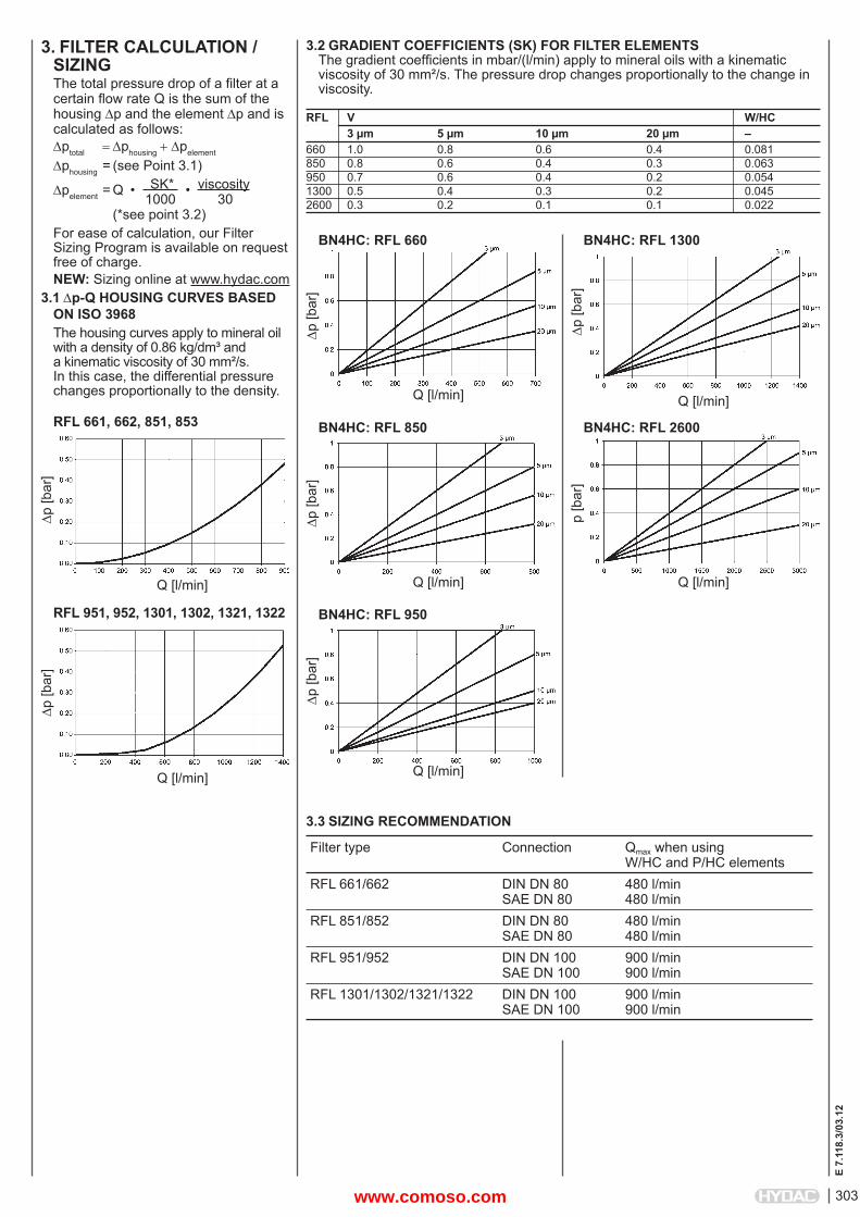
3. FILTER CALCULATION /SIZINGThe total pressure drop of a fi lter at a certain fl ow rate Q is the sum of the housing p and the element p and is calculated as follows:ptotal phousingpelement
phousing = (see Point 3.1)
pelement = Q • SK* • viscosity 1000 30 (*see point 3.2) For ease of calculation, our Filter Sizing Program is available on request free of charge.NEW: Sizing online at www.hydac.com
3.1 p-Q HOUSING CURVES BASED ON ISO 3968The housing curves apply to mineral oil with a density of 0.86 kg/dm³ and a kinematic viscosity of 30 mm²/s. In this case, the differential pressure changes proportionally to the density.
RFL 661, 662, 851, 853
p [b
ar]
Q [l/min]
RFL 951, 952, 1301, 1302, 1321, 1322
p [b
ar]
Q [l/min]
3.2 GRADIENT COEFFICIENTS (SK) FOR FILTER ELEMENTSThe gradient coeffi cients in mbar/(l/min) apply to mineral oils with a kinematic viscosity of 30 mm²/s. The pressure drop changes proportionally to the change in viscosity.
RFL V W/HC 3 μm 5 μm 10 μm 20 μm –660 1.0 0.8 0.6 0.4 0.081850 0.8 0.6 0.4 0.3 0.063950 0.7 0.6 0.4 0.2 0.0541300 0.5 0.4 0.3 0.2 0.0452600 0.3 0.2 0.1 0.1 0.022
p [b
ar]
Q [l/min]
BN4HC: RFL 660
p [b
ar]
Q [l/min]
BN4HC: RFL 950
p [b
ar]
Q [l/min]
BN4HC: RFL 850
p [b
ar]
Q [l/min]
BN4HC: RFL 1300
p [b
ar]
Q [l/min]
BN4HC: RFL 2600
3.3 SIZING RECOMMENDATION
Filter type Connection Qmax when usingW/HC and P/HC elements
RFL 661/662 DIN DN 80SAE DN 80
480 l/min480 l/min
RFL 851/852 DIN DN 80SAE DN 80
480 l/min480 l/min
RFL 951/952 DIN DN 100SAE DN 100
900 l/min900 l/min
RFL 1301/1302/1321/1322 DIN DN 100SAE DN 100
900 l/min900 l/min
www.comoso.com
304
E 7.
118.
3/03
.12
NOTEThe information in this brochure relates to the operating conditions and applications described.For applications and operating conditions not described, please contact the relevant technical department. Subject to technical modifi cations.
HYDAC FILTERTECHNIK GMBHIndustriegebietD-66280 Sulzbach/Saar, GermanyTel.: 0 68 97 / 509-01Fax: 0 68 97 / 509-300Internet: www.hydac.comE-mail: fi [email protected]
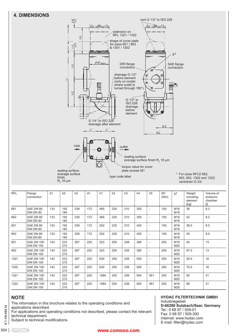
outletinlet
RFL Flange b1 b2 b3 d1 h1 h2 h3 h4 h5 M1 g1 Weight Volume of connection (Nm) including pressure element chamber [kg] [l]661 SAE DN 80 133 192 239 172 465 230 210 350 - 150 M16 36 8.2 DIN DN 80 184 M16 662 SAE DN 80 133 192 239 172 465 230 210 350 - 150 M16 42 8.2 DIN DN 80 184 M16 851 SAE DN 80 133 192 239 172 552 230 210 420 - 150 M16 38.5 9.5 DIN DN 80 184 M16 853 SAE DN 80 133 192 239 172 552 230 210 420 - 150 M16 45 9.5 DIN DN 80 184 M16 951 SAE DN 100 143 223 267 220 523 250 238 380 - 250 M16 54 13 DIN DN 100 215 M20 952 SAE DN 100 143 223 267 220 523 250 238 380 - 250 M16 67.5 13 DIN DN 100 215 M20 1301 SAE DN 100 143 223 267 220 630 250 238 500 - 250 M16 55.5 16 DIN DN 100 215 M20 1302 SAE DN 100 143 223 267 220 630 250 238 500 - 250 M16 75.5 16 DIN DN 100 215 M20 1321 SAE DN 100 143 223 267 220 1084 250 238 940 561 250 M16 82 31 DIN DN 100 215 M20 1322 SAE DN 100 143 223 267 220 1084 250 238 940 561 250 M16 96 31 DIN DN 100 215 M20
4. DIMENSIONS
type code label
torque value for coverplate screws M1sealing surface:
average surface fi nishRZ 16 μm
sealing surface:average surface fi nish RZ 16 μm
G 1/4* to ISO 228drainage after element
G 1/2* to ISO 228drainage before element
drainage G 1/2*before element(only on modelwhere outlet isturned through 180°)
DIN fl angeconnection
SAE fl angeconnection
g1
shape of cover platefor sizes 851 / 853& 1301 / 1302
extension onRFL 1321 / 1322
vent G 1/2* to ISO 228
* For sizes RFLD 662, 853, 952, 1302 and 1322: vent/drain G 3/4
www.comoso.com
305
E 7.
114.
5/03
.12
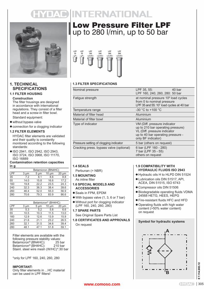
Low Pressure Filter LPFup to 280 l/min, up to 50 bar
1. TECHNICALSPECIFICATIONS
1.1 FILTER HOUSINGConstructionThe fi lter housings are designed in accordance with international regulations. They consist of a fi lter head and a screw-in fi lter bowl.Standard equipment:
without bypass valveconnection for a clogging indicator1.2 FILTER ELEMENTS
HYDAC fi lter elements are validated and their quality is constantly monitored according to the following standards:
ISO 2941, ISO 2942, ISO 2943, ISO 3724, ISO 3968, ISO 11170,ISO 16889
Contamination retention capacities in g Betamicron (BN4HC)LPF 3 μm 5 μm 10 μm 20 μm35 7.2 8.1 8.6 8.855 14.0 15.8 16.6 17.2160 19.8 22.2 23.5 24.3240 32.3 36.3 38.4 39.6260 46.4 52.0 55.0 56.9280 70.6 79.3 83.9 86.6
Betamicron® (BH4HC)LPF 3 μm 5 μm 10 μm 20 μm35 5.3 5.2 5.8 6.655 10.5 10.3 11.5 13.0160 12.9 12.6 13.9 15.9240 21.6 21.1 23.2 26.5260 32.1 31.5 34.6 39.4280 48.1 47.1 51.8 59.1
Filter elements are available with the following pressure stability values:Betamicron® (BN4HC): 25 barBetamicron® (BH4HC): 210 barStainl. steel wire mesh (W/HC)*: 30 bar
*only for LPF 160, 240, 260, 280
IMPORTANT:Only fi lter elements in ...HC material can be used in LPF fi lters!
1.4 SEALSPerbunan (= NBR)
1.5 MOUNTINGAs inline fi lter
1.6 SPECIAL MODELS AND ACCESSORIES
Seals in FPM, EPDMWith bypass valve (1, 3, 6 or 7 bar)Without port for clogging indicator
(LPF 160, 240, 260, 280)1.7 SPARE PARTS
See Original Spare Parts List1.8 CERTIFICATES AND APPROVALS
On request
1.3 FILTER SPECIFICATIONS
Nominal pressure LPF 35, 55: 40 bar LPF 160, 240, 260, 280: 50 bar Fatigue strength at nominal pressure 106 load cycles from 0 to nominal pressure LPF 35 and 55: 107 load cycles at 40 bar Temperature range -30 °C to +100 °C Material of fi lter head Aluminium Material of fi lter bowl Aluminium Type of indicator VM (Diff. pressure indicator up to 210 bar operating pressure) VL (Diff. pressure indicator up to 40 bar operating pressure - only BF indicator) Pressure setting of clogging indicator 5 bar (others on request) Cracking press. bypass valve (optional) 6 bar (LPF 160 - 280) 7 bar (LPF 35 - 55) others on request
Symbol for hydraulic systems
LPF35
LPF55
LPF160
LPF240
LPF260
1.9 COMPATIBILITY WITH HYDRAULIC FLUIDS ISO 2943
Hydraulic oils H to HLPD DIN 51524Lubrication oils DIN 51517, API,
ACEA, DIN 51515, ISO 6743Compressor oils DIN 51506Biodegradable operating fl uids VDMA
24568 HETG, HEES, HEPGFire-resistant fl uids HFC and HFDOperating fl uids with high water
content (>50% water content) on request
E 7.
114.
5/03
.12
LPF280
www.comoso.com
306
E 7.
114.
5/03
.12
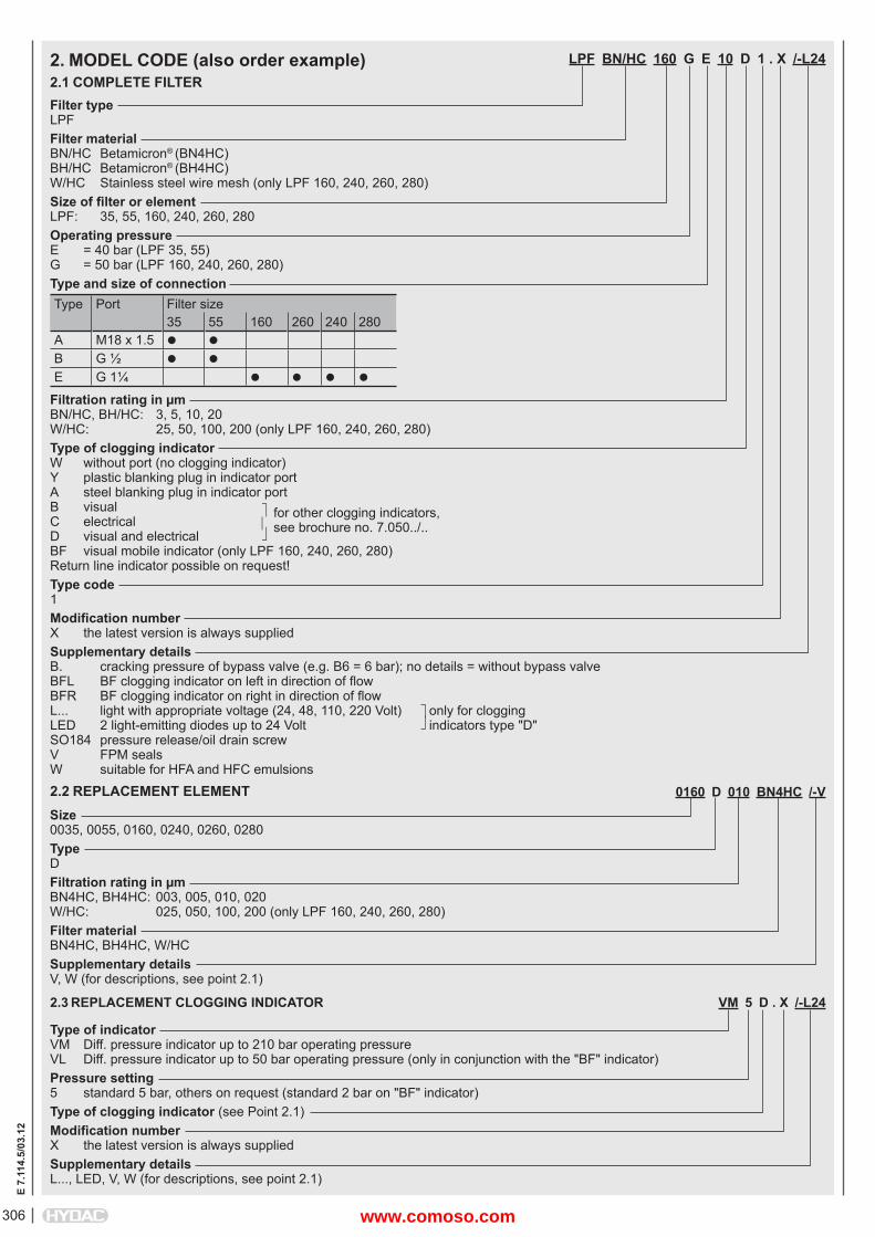
LPF BN/HC 160 G E 10 D 1 . X /-L24
Filter typeLPFFilter materialBN/HC Betamicron® (BN4HC)BH/HC Betamicron® (BH4HC)W/HC Stainless steel wire mesh (only LPF 160, 240, 260, 280)Size of fi lter or elementLPF: 35, 55, 160, 240, 260, 280Operating pressureE = 40 bar (LPF 35, 55)G = 50 bar (LPF 160, 240, 260, 280)Type and size of connectionType Port Filter size
35 55 160 260 240 280A M18 x 1.5 B G ½ E G 1¼
Filtration rating in μmBN/HC, BH/HC: 3, 5, 10, 20W/HC: 25, 50, 100, 200 (only LPF 160, 240, 260, 280)Type of clogging indicatorW without port (no clogging indicator)Y plastic blanking plug in indicator portA steel blanking plug in indicator portB visual for other clogging indicators,C electrical see brochure no. 7.050../..D visual and electrical BF visual mobile indicator (only LPF 160, 240, 260, 280)Return line indicator possible on request!Type code1 Modifi cation numberX the latest version is always suppliedSupplementary detailsB. cracking pressure of bypass valve (e.g. B6 = 6 bar); no details = without bypass valveBFL BF clogging indicator on left in direction of fl owBFR BF clogging indicator on right in direction of fl owL... light with appropriate voltage (24, 48, 110, 220 Volt) only for clogging LED 2 light-emitting diodes up to 24 Volt indicators type "D"SO184 pressure release/oil drain screwV FPM sealsW suitable for HFA and HFC emulsions
2. MODEL CODE (also order example)2.1 COMPLETE FILTER
0160 D 010 BN4HC /-V
Size0035, 0055, 0160, 0240, 0260, 0280TypeDFiltration rating in μmBN4HC, BH4HC: 003, 005, 010, 020W/HC: 025, 050, 100, 200 (only LPF 160, 240, 260, 280)Filter materialBN4HC, BH4HC, W/HCSupplementary detailsV, W (for descriptions, see point 2.1)
2.2 REPLACEMENT ELEMENT
2.3 REPLACEMENT CLOGGING INDICATOR VM 5 D . X /-L24
Type of indicatorVM Diff. pressure indicator up to 210 bar operating pressureVL Diff. pressure indicator up to 50 bar operating pressure (only in conjunction with the "BF" indicator)Pressure setting5 standard 5 bar, others on request (standard 2 bar on "BF" indicator)Type of clogging indicator (see Point 2.1)Modifi cation numberX the latest version is always suppliedSupplementary detailsL..., LED, V, W (for descriptions, see point 2.1)
www.comoso.com
307
E 7.
114.
5/03
.12
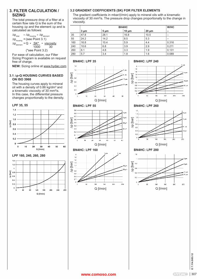
3. FILTER CALCULATION /SIZINGThe total pressure drop of a fi lter at a certain fl ow rate Q is the sum of the housing p and the element p and is calculated as follows:ptotal phousingpelement
phousing = (see Point 3.1)pelement = Q • SK* • viscosity 1000 30 (*see Point 3.2)For ease of calculation, our Filter Sizing Program is available on request free of charge.NEW: Sizing online at www.hydac.com
3.1 p-Q HOUSING CURVES BASED ON ISO 3968The housing curves apply to mineral oil with a density of 0.86 kg/dm³ and a kinematic viscosity of 30 mm²/s. In this case, the differential pressure changes proportionally to the density.
3.2 GRADIENT COEFFICIENTS (SK) FOR FILTER ELEMENTSThe gradient coeffi cients in mbar/(l/min) apply to mineral oils with a kinematic viscosity of 30 mm²/s. The pressure drop changes proportionally to the change in viscosity.
LPF 35, 55
p [b
ar]
Q [l/min]
BN4HC: LPF 35
p [b
ar]
BN4HC: LPF 55
p [b
ar]
Q [l/min]
BN4HC: LPF 240
p [b
ar]
Q [l/min]
LPF 160, 240, 260, 280
p [b
ar]
Q [l/min]
p [b
ar]
Q [l/min]
BN4HC: LPF 260
Q [l/min]
p [b
ar]
BN4HC: LPF 160
Q [l/min]
p [b
ar]
Q [l/min]
BN4HC: LPF 280
BH4HC W/HC3 μm 5 μm 10 μm 20 μm –
35 47.8 28.1 16.8 10.5 –55 24.2 14.2 8.5 5.3 –160 16.8 10.4 5.9 4.4 0.316240 10.6 6.8 3.9 2.9 0.211260 8.1 4.8 3.3 1.9 0.131280 5.7 3.4 1.8 1.6 0.089
www.comoso.com
308
E 7.
114.
5/03
.12
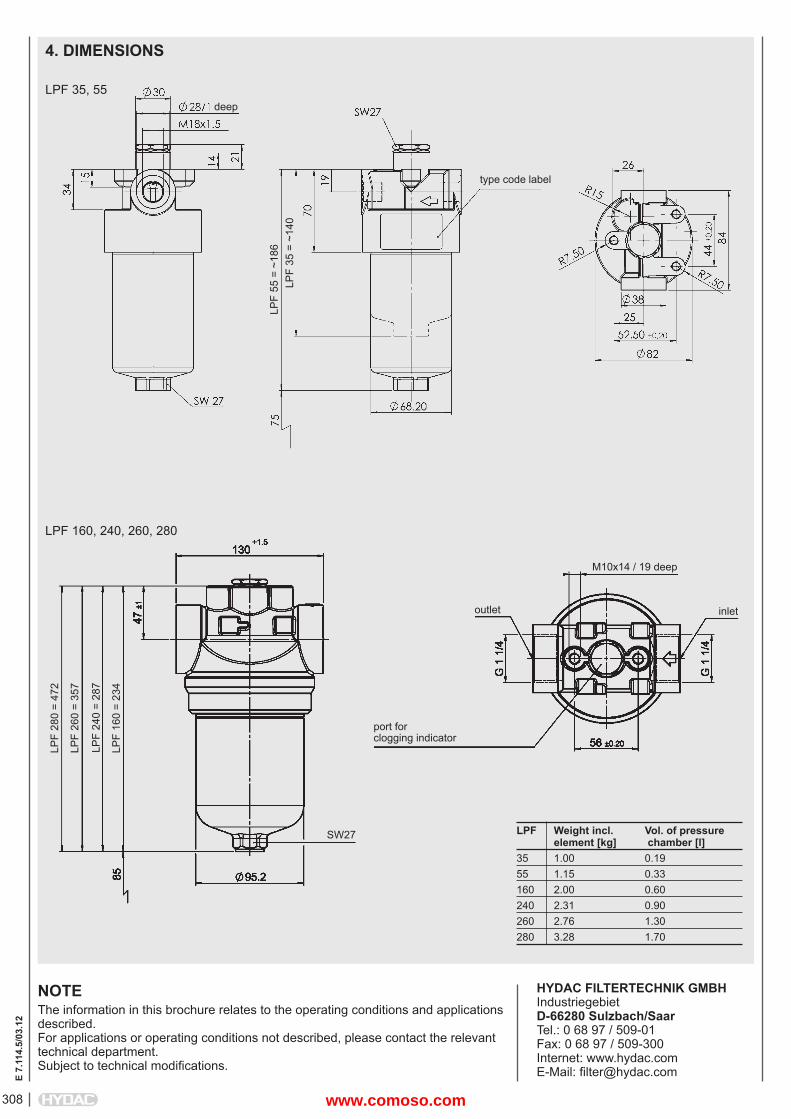
4. DIMENSIONS
LPF 35, 55
NOTEThe information in this brochure relates to the operating conditions and applications described.For applications or operating conditions not described, please contact the relevant technical department. Subject to technical modifi cations.
HYDAC FILTERTECHNIK GMBHIndustriegebietD-66280 Sulzbach/SaarTel.: 0 68 97 / 509-01Fax: 0 68 97 / 509-300Internet: www.hydac.comE-Mail: fi [email protected]
LPF 160, 240, 260, 280
type code label
LPF
55 =
~18
6
deep
LPF
35 =
~14
0
LPF
280
= 47
2
LPF
260
= 35
7
M10x14 / 19 deep
LPF
240
= 28
7
LPF
160
= 23
4
LPF Weight incl. Vol. of pressure element [kg] chamber [l]35 1.00 0.1955 1.15 0.33160 2.00 0.60240 2.31 0.90260 2.76 1.30280 3.28 1.70
inletoutlet
port forclogging indicator
SW27
www.comoso.com
309
E 7.
563.
3/03
.12
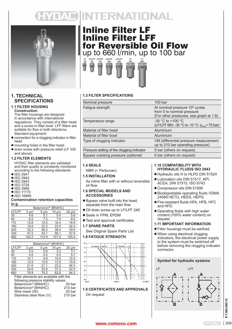
Inline Filter LFInline Filter LFFfor Reversible Oil Flowup to 660 l/min, up to 100 bar
1. TECHNICALSPECIFICATIONS
1.1 FILTER HOUSINGConstructionThe fi lter housings are designed in accordance with international regulations. They consist of a fi lter head and a screw-in fi lter bowl. LFF fi lters are suitable for fl ow in both directions.Standard equipment:
connection for a clogging indicator in fi lter head
mounting holes in the fi lter headdrain screw with pressure relief (LF 330
and above)1.2 FILTER ELEMENTS
HYDAC fi lter elements are validated and their quality is constantly monitored according to the following standards:
ISO 2941ISO 2942 ISO 2943 ISO 3724ISO 3968 ISO 11170ISO 16889Contamination retention capacities in g Betamicron® (BN4HC)LF/LFF 3 μm 5 μm 10 μm 20 μm30 4.6 5.1 5.4 5.660 6.5 7.3 7.8 8.0110 13.8 15.5 16.4 16.9160 19.8 22.2 23.5 24.3240 32.3 36.3 38.4 39.6330 47.2 53.1 56.1 57.9660 102.2 114.9 121.5 125.4
Betamicron® (BH4HC)LF/LFF 3 μm 5 μm 10 μm 20 μm30 3.0 2.9 3.2 3.760 4.6 4.5 5.0 5.7110 10.1 9.9 10.9 12.4160 12.9 12.6 13.9 15.9240 21.6 21.1 23.2 26.5330 34.6 33.9 37.2 42.5660 76.8 75.2 82.6 94.3
Filter elements are available with the following pressure stability values:Betamicron® (BN4HC): 20 barBetamicron® (BH4HC): 210 barWire mesh (W): 20 barStainless steel fi bre (V): 210 bar
1.4 SEALSNBR (= Perbunan)
1.5 INSTALLATIONAs inline fi lter with or without reversible oil fl ow
1.6 SPECIAL MODELS AND ACCESSORIES
Bypass valve built into the head, separate from the main fl ow
Oil drain screw up to LF/LFF 240Seals in FPM, EPDMTest and approval certifi cates1.7 SPARE PARTS
See Original Spare Parts List1.8 FATIGUE STRENGTH
1.9 CERTIFICATES AND APPROVALSOn request
1.10 COMPATIBILITY WITH HYDRAULIC FLUIDS ISO 2943
Hydraulic oils H to HLPD DIN 51524Lubrication oils DIN 51517, API,
ACEA, DIN 51515, ISO 6743Compressor oils DIN 51506Biodegradable operating fl uids VDMA
24568 HETG, HEES, HEPGFire-resistant fl uids HFA, HFB, HFC
and HFDOperating fl uids with high water
content (>50% water content) on request
1.11 IMPORTANT INFORMATION Filter housings must be earthed.When using electrical clogging
indicators, the electrical power supply to the system must be switched off before removing the clogging indicatorconnector.
1.3 FILTER SPECIFICATIONS
Nominal pressure 100 bar Fatigue strength At nominal pressure 106 cycles from 0 to nominal pressure (For other pressures, see graph at 1.8) Temperature range -30 °C to +100 °C (LF/LFF 660: -30 °C to -10 °C: pmax= 75 bar) Material of fi lter head Aluminium Material of fi lter bowl Aluminium Type of clogging indicator VM (differential pressure measurement up to 210 bar operating pressure) Pressure setting of the clogging indicator 5 bar (others on request) Bypass cracking pressure (optional) 6 bar (others on request)
LF30
LF/LFF 110
LF/LFF 160
LF/LFF 240
LF330
LF660
LF/LFF 60
E 7.
563.
3/03
.12
Symbol for hydraulic systems
LF LFF
www.comoso.com
310
E 7.
563.
3/03
.12
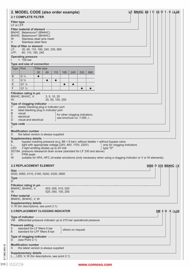
LF BN/HC 60 I C 10 D 1 . X /-L24
Filter typeLF or LFFFilter material of elementBN/HC Betamicron® (BN4HC)BH/HC Betamicron® (BH4HC)W Stainless steel wire meshV Stainless steel fi bre Size of fi lter or elementLF: 30, 60, 110, 160, 240, 330, 660LFF: 60, 110, 160, 240Operating pressureI = 100 barType and size of connectionType Port Filter size
30 60 110 160 240 330 660B G ½ C G ¾ E G1 ¼ F G1 ½
Filtration rating in μmBN/HC, BH/HC, V: 3, 5, 10, 20W: 25, 50, 100, 200Type of clogging indicatorY plastic blanking plug in indicator portA steel blanking plug in indicator portB visual for other clogging indicators,C electrical see brochure no. 7.050../..D visual and electricalType code1Modifi cation numberX the latest version is always suppliedSupplementary detailsB. bypass cracking pressure (e.g. B6 = 6 bar); without details = without bypass valveL... light with appropriate voltage (24V, 48V, 110V, 220V) only for clogging indicatorsLED 2 light emitting diodes up to 24 Volt type "D"SO184 pressure release/oil drain screw (standard for LF 330 and above)V FPM sealsW suitable for HFA, HFC oil-water emulsions (only necessary when using a clogging indicator or V or W elements)
2. MODEL CODE (also order example)2.1 COMPLETE FILTER
0060 D 010 BN4HC /-V
Size0030, 0060, 0110, 0160, 0240, 0330, 0660TypeDFiltration rating in μmBN4HC, BH4HC, V: 003, 005, 010, 020W: 025, 050, 100, 200Filter materialBN4HC, BH4HC, V, WSupplementary detailsV, W (for descriptions, see point 2.1)
2.2 REPLACEMENT ELEMENT
2.3 REPLACEMENT CLOGGING INDICATOR VM 5 D . X /-L24
Type of indicatorVM differential pressure indicator up to 210 bar operational pressure
Pressure setting5 standard for LF fi lters 5 bar others on request8 standard for LFF fi lters 8 bar
Type of clogging indicatorD (see Point 2.1)
Modifi cation numberX the latest version is always supplied
Supplementary detailsL..., LED, V, W (for descriptions, see point 2.1)
www.comoso.com
311
E 7.
563.
3/03
.12
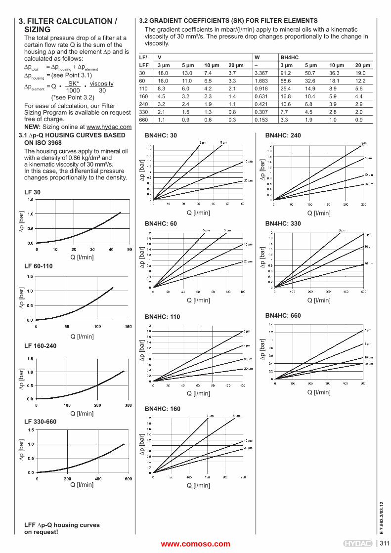
3. FILTER CALCULATION /SIZINGThe total pressure drop of a fi lter at a certain fl ow rate Q is the sum of the housing p and the element p and is calculated as follows:ptotal phousingpelement
phousing = (see Point 3.1)
pelement = Q • SK* • viscosity 1000 30 (*see Point 3.2)For ease of calculation, our Filter Sizing Program is available on request free of charge.NEW: Sizing online at www.hydac.com
3.1 p-Q HOUSING CURVES BASED ON ISO 3968The housing curves apply to mineral oil with a density of 0.86 kg/dm³ and a kinematic viscosity of 30 mm²/s. In this case, the differential pressure changes proportionally to the density.
3.2 GRADIENT COEFFICIENTS (SK) FOR FILTER ELEMENTSThe gradient coeffi cients in mbar/(l/min) apply to mineral oils with a kinematic viscosity of 30 mm²/s. The pressure drop changes proportionally to the change in viscosity.
LF 30
p [b
ar]
Q [l/min]LF 60-110
p [b
ar]
Q [l/min]LF 160-240
p [b
ar]
Q [l/min]LF 330-660
p [b
ar]
Q [l/min]
LF/ V W BH4HCLFF 3 μm 5 μm 10 μm 20 μm – 3 μm 5 μm 10 μm 20 μm30 18.0 13.0 7.4 3.7 3.367 91.2 50.7 36.3 19.060 16.0 11.0 6.5 3.3 1.683 58.6 32.6 18.1 12.2110 8.3 6.0 4.2 2.1 0.918 25.4 14.9 8.9 5.6160 4.5 3.2 2.3 1.4 0.631 16.8 10.4 5.9 4.4240 3.2 2.4 1.9 1.1 0.421 10.6 6.8 3.9 2.9330 2.1 1.5 1.3 0.8 0.307 7.7 4.5 2.8 2.0660 1.1 0.9 0.6 0.3 0.153 3.3 1.9 1.0 0.9
p [b
ar]
Q [l/min]
BN4HC: 30p
[bar
]
Q [l/min]
BN4HC: 60
p [b
ar]
Q [l/min]
BN4HC: 240
p [b
ar]
Q [l/min]
BN4HC: 330
p [b
ar]
Q [l/min]
BN4HC: 160
p [b
ar]
Q [l/min]
BN4HC: 110
p [b
ar]
Q [l/min]
BN4HC: 660
LFF p-Q housing curves on request!
www.comoso.com
312
E 7.
563.
3/03
.12
NOTEThe information in this brochure relates to the operating conditions and applications described.For applications or operating conditions not described, please contact the relevant technical department. Subject to technical modifi cations.
HYDAC FILTERTECHNIK GMBHIndustriegebietD-66280 Sulzbach/Saar, GermanyTel.: 0 68 97 / 509-01Fax: 0 68 97 / 509-300Internet: www.hydac.comE-mail: fi [email protected]
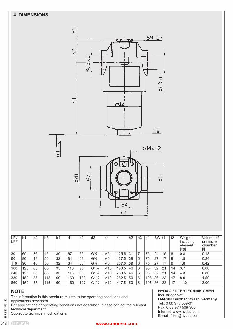
4. DIMENSIONS
LF / b1 b2 b3 b4 d1 d2 d3 d4 h1 h2 h3 h4 SW t1 t2 Weight Volume ofLFF including pressure element chamber [kg] [l]30 69 36 45 30 67 52 G½ M5 125.5 31 7 75 24 15 8 0.8 0.1360 90 48 56 32 84 68 G¾ M6 137.5 39 6 75 27 17 9 1.5 0.24110 90 48 56 32 84 68 G¾ M6 207.0 39 6 75 27 17 9 1.8 0.42160 125 65 85 35 116 95 G1¼ M10 190.5 46 6 95 32 21 14 3.7 0.60240 125 65 85 35 116 95 G1¼ M10 250.5 46 6 95 32 21 14 4.3 0.80330 159 85 115 60 160 130 G1½ M12 252.5 50 6 105 36 23 17 8.0 1.50660 159 85 115 60 160 127 G1½ M12 417.5 50 6 105 36 23 17 11.0 3.00
www.comoso.com
313
E 7.
557.
3/03
.12
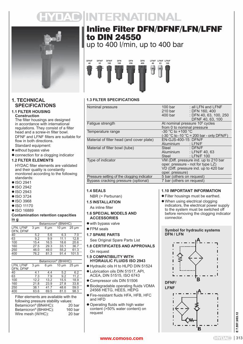
Inline Filter DFN/DFNF/LFN/LFNF to DIN 24550up to 400 l/min, up to 400 bar
1. TECHNICALSPECIFICATIONS
1.1 FILTER HOUSINGConstructionThe fi lter housings are designed in accordance with international regulations. They consist of a fi lter head and a screw-in fi lter bowl.DFNF and LFNF fi lters are suitable for fl ow in both directions.Standard equipment:
without bypass valveconnection for a clogging indicator1.2 FILTER ELEMENTS
HYDAC fi lter elements are validated and their quality is constantly monitored according to the following standards:
ISO 2941ISO 2942 ISO 2943 ISO 3724ISO 3968 ISO 11170ISO 16889Contamination retention capacities in g Betamicron® (BN4HC)LFN, LFNF 3 μm 6 μm 10 μm 25 μmDFN, DFNF40 5.2 5.6 6.3 7.063 9.2 9.9 11.1 12.8100 15.4 16.5 18.6 20.6160 27.5 29.3 33.1 36.7250 46.0 49.0 55.2 61.3400 76.2 81.3 91.4 101.5
Betamicron® (BH4HC)LFN, LFNF 3 μm 6 μm 10 μm 25 μmDFN, DFNF40 4.1 4.4 5.2 6.263 7.3 7.9 9.2 11.2100 12.2 13.2 15.5 18.9160 21.8 23.9 27.8 33.8250 38.1 41.7 48.6 59.0400 63.6 69.5 81.0 98.3
Filter elements are available with the following pressure stability values:Betamicron® (BN4HC): 20 barBetamicron® (BH4HC): 160 barWire mesh (W/HC): 20 bar
1.4 SEALSNBR (= Perbunan)
1.5 INSTALLATIONAs inline fi lter
1.6 SPECIAL MODELS AND ACCESSORIES
with bypass valveFPM seals1.7 SPARE PARTS
See Original Spare Parts List1.8 CERTIFICATES AND APPROVALS
On request1.9 COMPATIBILITY WITH
HYDRAULIC FLUIDS ISO 2943Hydraulic oils H to HLPD DIN 51524Lubrication oils DIN 51517, API,
ACEA, DIN 51515, ISO 6743Compressor oils DIN 51506Biodegradable operating fl uids VDMA
24568 HETG, HEES, HEPGFire-resistant fl uids HFA, HFB, HFC
and HFDOperating fl uids with high water
content (>50% water content) on request
1.10 IMPORTANT INFORMATION Filter housings must be earthed.When using electrical clogging
indicators, the electrical power supply to the system must be switched off before removing the clogging indicatorconnector.
1.3 FILTER SPECIFICATIONS
Nominal pressure 100 bar : all LFN and LFNF 210 bar : DFN 160, 400 400 bar : DFN 40, 63, 100, 250 DFNF 40, 63, 100 Fatigue strength At nominal pressure 106 cycles from 0 to nominal pressure Temperature range -30 °C to +100 °C (-30 °C to -10 °C = 200 bar - only DFN/F) Material of fi lter head (and cover plate) EN-GJS-400-15 : DFN/F Aluminium : LFN/F Material of fi lter bowl (tube) Steel : DFN/F Aluminium : LFN/F 40, 63 Steel : LFN/F 100 Type of indicator VM (Diff. pressure ind. up to 210 bar oper. pressure - not for type LZ) VD (Diff. pressure ind. up to 420 bar oper. pressure) Pressure setting of the clogging indicator 5 bar (others on request) Bypass cracking pressure (optional) 7 bar (others on request)
Symbol for hydraulic systemsDFN / LFN
LFN/F 40
E 7.
557.
3/03
.12
LFN/F 63
LFN/F 100
DFN/F40
DFN/F63
DFN/F100
DFN160
DFN250
DFN400
DFNF/LFNF
www.comoso.com
314
E 7.
557.
3/03
.12
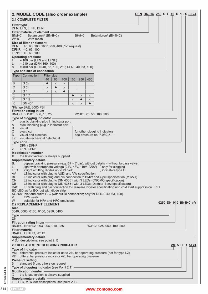
DFN BN/HC 250 S F 10 D 1 . X /-L24
Filter typeDFN, LFN, LFNF, DFNFFilter material of elementBN/HC Betamicron® (BN4HC) BH/HC Betamicron® (BH4HC)W/HC Wire meshSize of fi lter or elementDFN: 40, 63, 100, 160*, 250, 400 (*on request)DFNF: 40, 63, 100LFN/F: 40, 63, 100Operating pressureI = 100 bar (LFN and LFNF)L = 210 bar (DFN 160, 400)S = 400 bar (DFN 40, 63, 100, 250; DFNF 40, 63, 100)Type and size of connectionType Connection Filter size
40 63 100 160 250 400B G ½ x xC G ¾ x xD G 1 x x E G 1¼ x xF G 1½ x xK DN 40* x x *Flange SAE, 6000 PSIFiltration rating in μmBN/HC, BH/HC: 3, 6, 10, 25 W/HC: 25, 50, 100, 200Type of clogging indicatorY plastic blanking plug in indicator portA steel blanking plug in indicator portB visual C electrical for other clogging indicators,D visual and electrical see brochure no. 7.050../..LZ visual-mechanical / electricalType code1 DFN / DFNF2 LFN / LFNFModifi cation numberX the latest version is always suppliedSupplementary detailsB. bypass cracking pressure (e.g. B7 = 7 bar); without details = without bypass valveL... light with appropriate voltage (24V, 48V, 110V, 220V) only for cloggingLED 2 light emitting diodes up to 24 Volt indicators type DAV LZ indicator with plug to AUDI and VW specifi cationBO LZ indicator with plug and pin connection to BMW and Opel specifi cation (M12x1)CN LZ indicator with plug to DIN 43651 with 3 LEDs (CNOMO specifi cation)DB LZ indicator with plug to DIN 43651 with 3 LEDs (Daimler-Benz specifi cation)D4C LZ with plug and pin connection to Daimler-Chrysler specifi cation and cold start suppression 30°CBO-LED as for BO, but with diode stripSO368 inlet and outlet G ½ (without RI connection; only for DFN/F 40, 63, 100)V FPM sealsW suitable for HFA and HFC emulsions
2. MODEL CODE (also order example)2.1 COMPLETE FILTER
0250 DN 010 BN4HC /-VSize0040, 0063, 0100, 0160, 0250, 0400TypeDNFiltration rating in μmBN4HC, BH4HC: 003, 006, 010, 025 W/HC: 025, 050, 100, 200Filter materialBN4HC, BH4HC, W/HCSupplementary detailsV (for descriptions, see point 2.1)
2.2 REPLACEMENT ELEMENT
2.3 REPLACEMENT CLOGGING INDICATOR VM 5 D . X /-L24Type of indicatorVM differential pressure indicator up to 210 bar operating pressure (not for type LZ)VD differential pressure indicator 420 bar operating pressurePressure setting5 standard 5 bar, others on requestType of clogging indicator (see Point 2.1)Modifi cation numberX the latest version is always suppliedSupplementary detailsL..., LED, V, W (for descriptions, see point 2.1)
www.comoso.com
315
E 7.
557.
3/03
.12
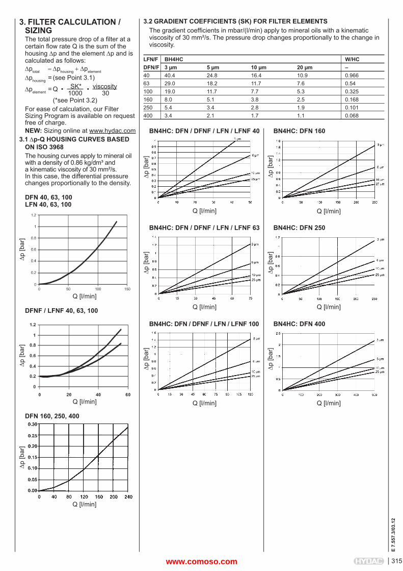
3. FILTER CALCULATION /SIZINGThe total pressure drop of a fi lter at a certain fl ow rate Q is the sum of the housing p and the element p and is calculated as follows:ptotal phousingpelement
phousing = (see Point 3.1)
pelement = Q • SK* • viscosity 1000 30 (*see Point 3.2)For ease of calculation, our Filter Sizing Program is available on request free of charge.NEW: Sizing online at www.hydac.com
3.1 p-Q HOUSING CURVES BASED ON ISO 3968The housing curves apply to mineral oil with a density of 0.86 kg/dm³ and a kinematic viscosity of 30 mm²/s. In this case, the differential pressure changes proportionally to the density.
3.2 GRADIENT COEFFICIENTS (SK) FOR FILTER ELEMENTSThe gradient coeffi cients in mbar/(l/min) apply to mineral oils with a kinematic viscosity of 30 mm²/s. The pressure drop changes proportionally to the change in viscosity.
DFN 40, 63, 100LFN 40, 63, 100
p [b
ar]
Q [l/min]
DFNF / LFNF 40, 63, 100
p [b
ar]
Q [l/min]
DFN 160, 250, 400
p [b
ar]
Q [l/min]
p [b
ar]
Q [l/min]
BN4HC: DFN / DFNF / LFN / LFNF 40
p [b
ar]
Q [l/min]
BN4HC: DFN / DFNF / LFN / LFNF 63
p [b
ar]
Q [l/min]
BN4HC: DFN 160
p [b
ar]
Q [l/min]
BN4HC: DFN 250
LFN/F BH4HC W/HCDFN/F 3 μm 5 μm 10 μm 20 μm –40 40.4 24.8 16.4 10.9 0.96663 29.0 18.2 11.7 7.6 0.54100 19.0 11.7 7.7 5.3 0.325160 8.0 5.1 3.8 2.5 0.168250 5.4 3.4 2.8 1.9 0.101400 3.4 2.1 1.7 1.1 0.068
p [b
ar]
Q [l/min]
BN4HC: DFN / DFNF / LFN / LFNF 100
p [b
ar]
Q [l/min]
BN4HC: DFN 400
www.comoso.com
316
E 7.
557.
3/03
.12
NOTEThe information in this brochure relates to the operating conditions and applications described.For applications and operating conditions not described, please contact the relevant technical department. Subject to technical modifi cations.
HYDAC FILTERTECHNIK GMBHIndustriegebietD-66280 Sulzbach/Saar, GermanyTel.: 0 68 97 / 509-01Fax: 0 68 97 / 509-300Internet: www.hydac.comE-mail: fi [email protected]
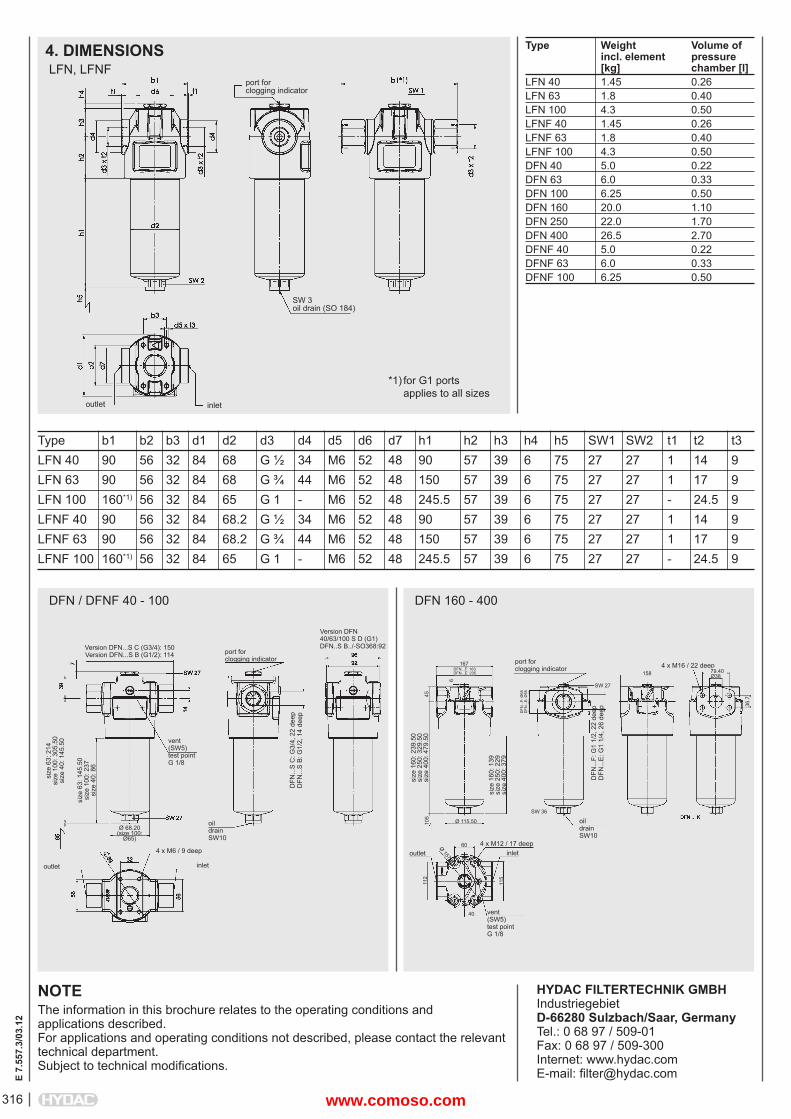
Type b1 b2 b3 d1 d2 d3 d4 d5 d6 d7 h1 h2 h3 h4 h5 SW1 SW2 t1 t2 t3LFN 40 90 56 32 84 68 G ½ 34 M6 52 48 90 57 39 6 75 27 27 1 14 9LFN 63 90 56 32 84 68 G ¾ 44 M6 52 48 150 57 39 6 75 27 27 1 17 9LFN 100 160*1) 56 32 84 65 G 1 - M6 52 48 245.5 57 39 6 75 27 27 - 24.5 9LFNF 40 90 56 32 84 68.2 G ½ 34 M6 52 48 90 57 39 6 75 27 27 1 14 9LFNF 63 90 56 32 84 68.2 G ¾ 44 M6 52 48 150 57 39 6 75 27 27 1 17 9LFNF 100 160*1) 56 32 84 65 G 1 - M6 52 48 245.5 57 39 6 75 27 27 - 24.5 9
4. DIMENSIONSLFN, LFNF
Type Weight Volume of incl. element pressure [kg] chamber [l]LFN 40 1.45 0.26LFN 63 1.8 0.40LFN 100 4.3 0.50LFNF 40 1.45 0.26LFNF 63 1.8 0.40LFNF 100 4.3 0.50DFN 40 5.0 0.22DFN 63 6.0 0.33DFN 100 6.25 0.50DFN 160 20.0 1.10DFN 250 22.0 1.70DFN 400 26.5 2.70DFNF 40 5.0 0.22DFNF 63 6.0 0.33DFNF 100 6.25 0.50
port for clogging indicator
SW 3oil drain (SO 184)
inletoutlet
DFN / DFNF 40 - 100
port forclogging indicator
vent (SW5)test point G 1/8
oildrain SW10
DFN
...S
C: G
3/4,
22
deep
DFN
...S
B: G
1/2,
14
deep
Version DFN 40/63/100 S D (G1)DFN..S B../-SO368:92
4 x M6 / 9 deep
inletoutlet
Ø 68.20(size 100:
Ø65)
size
63:
145
.50
size
100
: 237
size
40:
86
size
63:
214
size
100
: 305
.50
size
40:
145
.50
Version DFN...S C (G3/4): 150Version DFN...S B (G1/2): 114
DFN 160 - 400
port forclogging indicator
vent (SW5)test point G 1/8
oildrain SW10
DFN
...F:
G1
1/2,
22
deep
DFN
...E
: G1
1/4,
26
deep
4 x M12 / 17 deepinletoutlet
size
160
: 139
size
250
: 229
size
400
: 379
size
160
: 239
.50
size
250
: 329
.50
size
400
: 479
.50
4 x M16 / 22 deep
*1) for G1 ports applies to all sizes
45
6
167DFN...F: 163DFN...E: 235
SW 27
158 79.40Ø38
36.7
SW 36
DFN
...F:
Ø68
DFN
...E
: Ø55
Ø 115.50
60
105
40
112
115
Ø 157
www.comoso.com
317
E 7.
502.
2/03
.12
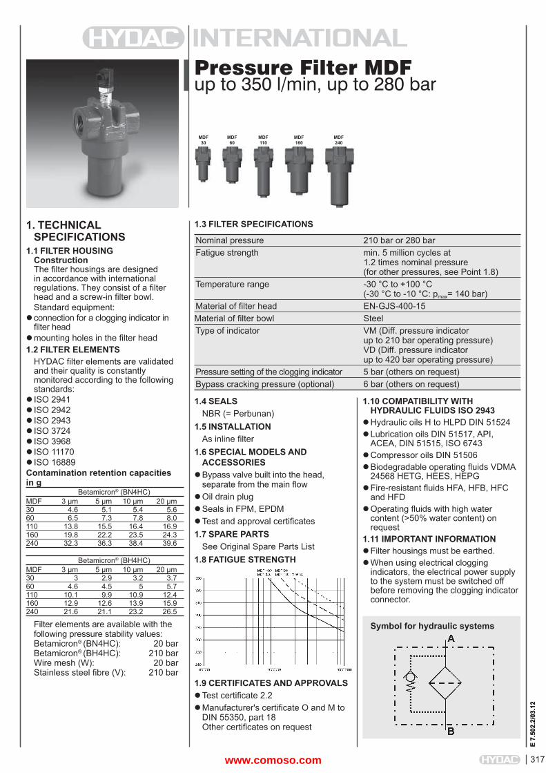
Pressure Filter MDFup to 350 l/min, up to 280 bar
1. TECHNICALSPECIFICATIONS
1.1 FILTER HOUSINGConstructionThe fi lter housings are designed in accordance with international regulations. They consist of a fi lter head and a screw-in fi lter bowl.Standard equipment:
connection for a clogging indicator in fi lter head
mounting holes in the fi lter head1.2 FILTER ELEMENTS
HYDAC fi lter elements are validated and their quality is constantly monitored according to the following standards:
ISO 2941ISO 2942 ISO 2943 ISO 3724ISO 3968 ISO 11170ISO 16889Contamination retention capacities in g Betamicron® (BN4HC)MDF 3 μm 5 μm 10 μm 20 μm30 4.6 5.1 5.4 5.660 6.5 7.3 7.8 8.0110 13.8 15.5 16.4 16.9160 19.8 22.2 23.5 24.3240 32.3 36.3 38.4 39.6
Betamicron® (BH4HC)MDF 3 μm 5 μm 10 μm 20 μm30 3 2.9 3.2 3.760 4.6 4.5 5 5.7110 10.1 9.9 10.9 12.4160 12.9 12.6 13.9 15.9240 21.6 21.1 23.2 26.5
Filter elements are available with the following pressure stability values:Betamicron® (BN4HC): 20 barBetamicron® (BH4HC): 210 barWire mesh (W): 20 barStainless steel fi bre (V): 210 bar
1.4 SEALSNBR (= Perbunan)
1.5 INSTALLATIONAs inline fi lter
1.6 SPECIAL MODELS AND ACCESSORIES
Bypass valve built into the head, separate from the main fl ow
Oil drain plugSeals in FPM, EPDMTest and approval certifi cates1.7 SPARE PARTS
See Original Spare Parts List1.8 FATIGUE STRENGTH
1.9 CERTIFICATES AND APPROVALSTest certifi cate 2.2Manufacturer's certifi cate O and M to
DIN 55350, part 18Other certifi cates on request
1.10 COMPATIBILITY WITH HYDRAULIC FLUIDS ISO 2943
Hydraulic oils H to HLPD DIN 51524Lubrication oils DIN 51517, API,
ACEA, DIN 51515, ISO 6743Compressor oils DIN 51506Biodegradable operating fl uids VDMA
24568 HETG, HEES, HEPGFire-resistant fl uids HFA, HFB, HFC
and HFDOperating fl uids with high water
content (>50% water content) on request
1.11 IMPORTANT INFORMATION Filter housings must be earthed.When using electrical clogging
indicators, the electrical power supply to the system must be switched off before removing the clogging indicatorconnector.
1.3 FILTER SPECIFICATIONS
Nominal pressure 210 bar or 280 bar Fatigue strength min. 5 million cycles at 1.2 times nominal pressure (for other pressures, see Point 1.8) Temperature range -30 °C to +100 °C (-30 °C to -10 °C: pmax= 140 bar) Material of fi lter head EN-GJS-400-15Material of fi lter bowl Steel Type of indicator VM (Diff. pressure indicator up to 210 bar operating pressure) VD (Diff. pressure indicator up to 420 bar operating pressure) Pressure setting of the clogging indicator 5 bar (others on request) Bypass cracking pressure (optional) 6 bar (others on request)
Symbol for hydraulic systems
MDF 30
MDF 60
MDF 110
MDF 160
MDF 240
E 7.
502.
2/03
.12
www.comoso.com
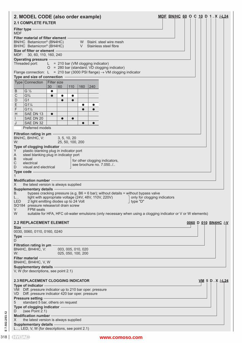
318
E 7.
502.
2/03
.12
MDF BN/HC 60 O C 10 D 1 . X /-L24
Filter typeMDFFilter material of fi lter elementBN/HC Betamicron® (BN4HC) W Stainl. steel wire meshBH/HC Betamicron® (BH4HC) V Stainless steel fi breSize of fi lter or elementMDF: 30, 60, 110, 160, 240Operating pressureThreaded port: L = 210 bar (VM clogging indicator) O = 280 bar (standard; VD clogging indicator)Flange connection: L = 210 bar (3000 PSI fl ange) VM clogging indicatorType and size of connectionType Connection Filter size
30 60 110 160 240B G ½ C G¾ D G1 E G1¼ F G1½ H SAE DN 13 I SAE DN 20 J SAE DN 32 Preferred modelsFiltration rating in μmBN/HC, BH/HC, V: 3, 5, 10, 20W: 25, 50, 100, 200Type of clogging indicatorY plastic blanking plug in indicator portA steel blanking plug in indicator portB visual for other clogging indicators,C electrical see brochure no. 7.050../..D visual and electricalType code1Modifi cation numberX the latest version is always suppliedSupplementary detailsB. bypass cracking pressure (e.g. B6 = 6 bar); without details = without bypass valveL... light with appropriate voltage (24V, 48V, 110V, 220V) only for clogging indicatorsLED 2 light emitting diodes up to 24 Volt type "D"SO184 pressure release/oil drain screw V FPM sealsW suitable for HFA, HFC oil-water emulsions (only necessary when using a clogging indicator or V or W elements)
2. MODEL CODE (also order example)2.1 COMPLETE FILTER
2.2 REPLACEMENT ELEMENT 0060 D 010 BN4HC /-VSize0030, 0060, 0110, 0160, 0240TypeDFiltration rating in μmBN4HC, BH4HC, V: 003, 005, 010, 020W: 025, 050, 100, 200Filter materialBN4HC, BH4HC, V, WSupplementary detailsV, W (for descriptions, see point 2.1)
2.3 REPLACEMENT CLOGGING INDICATOR VM 5 D . X /-L24Type of indicatorVM Diff. pressure indicator up to 210 bar oper. pressureVD Diff. pressure indicator 420 bar oper. pressurePressure setting5 standard 5 bar, others on requestType of clogging indicatorD (see Point 2.1)Modifi cation numberX the latest version is always suppliedSupplementary detailsL..., LED, V, W (for descriptions, see point 2.1)
www.comoso.com
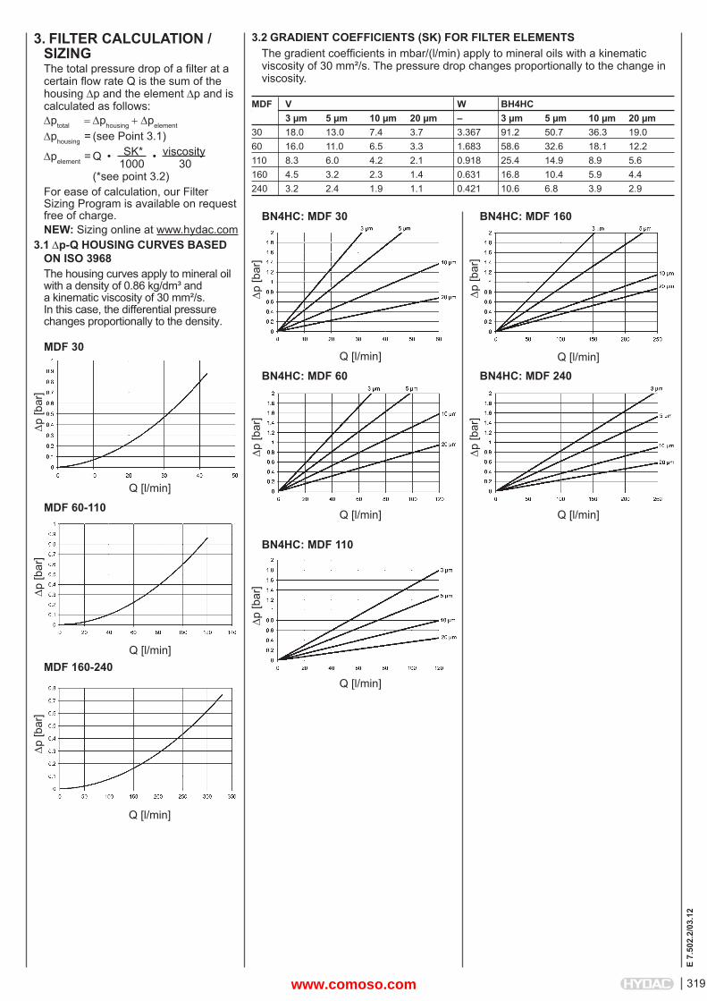
319
E 7.
502.
2/03
.12
3. FILTER CALCULATION /SIZINGThe total pressure drop of a fi lter at a certain fl ow rate Q is the sum of the housing p and the element p and is calculated as follows:ptotal phousingpelement
phousing = (see Point 3.1)
pelement = Q • SK* • viscosity 1000 30 (*see point 3.2) For ease of calculation, our Filter Sizing Program is available on request free of charge.NEW: Sizing online at www.hydac.com
3.1 p-Q HOUSING CURVES BASED ON ISO 3968The housing curves apply to mineral oil with a density of 0.86 kg/dm³ and a kinematic viscosity of 30 mm²/s. In this case, the differential pressure changes proportionally to the density.
3.2 GRADIENT COEFFICIENTS (SK) FOR FILTER ELEMENTSThe gradient coeffi cients in mbar/(l/min) apply to mineral oils with a kinematic viscosity of 30 mm²/s. The pressure drop changes proportionally to the change in viscosity.
MDF 30
p [b
ar]
Q [l/min]
MDF 60-110
p [b
ar]
Q [l/min]MDF 160-240
p [b
ar]
Q [l/min]
p [b
ar]
Q [l/min]
BN4HC: MDF 30
p [b
ar]
Q [l/min]
BN4HC: MDF 60
p [b
ar]
Q [l/min]
BN4HC: MDF 160
p [b
ar]
Q [l/min]
BN4HC: MDF 240
MDF V W BH4HC 3 μm 5 μm 10 μm 20 μm – 3 μm 5 μm 10 μm 20 μm30 18.0 13.0 7.4 3.7 3.367 91.2 50.7 36.3 19.060 16.0 11.0 6.5 3.3 1.683 58.6 32.6 18.1 12.2110 8.3 6.0 4.2 2.1 0.918 25.4 14.9 8.9 5.6160 4.5 3.2 2.3 1.4 0.631 16.8 10.4 5.9 4.4240 3.2 2.4 1.9 1.1 0.421 10.6 6.8 3.9 2.9
p [b
ar]
Q [l/min]
BN4HC: MDF 110
www.comoso.com
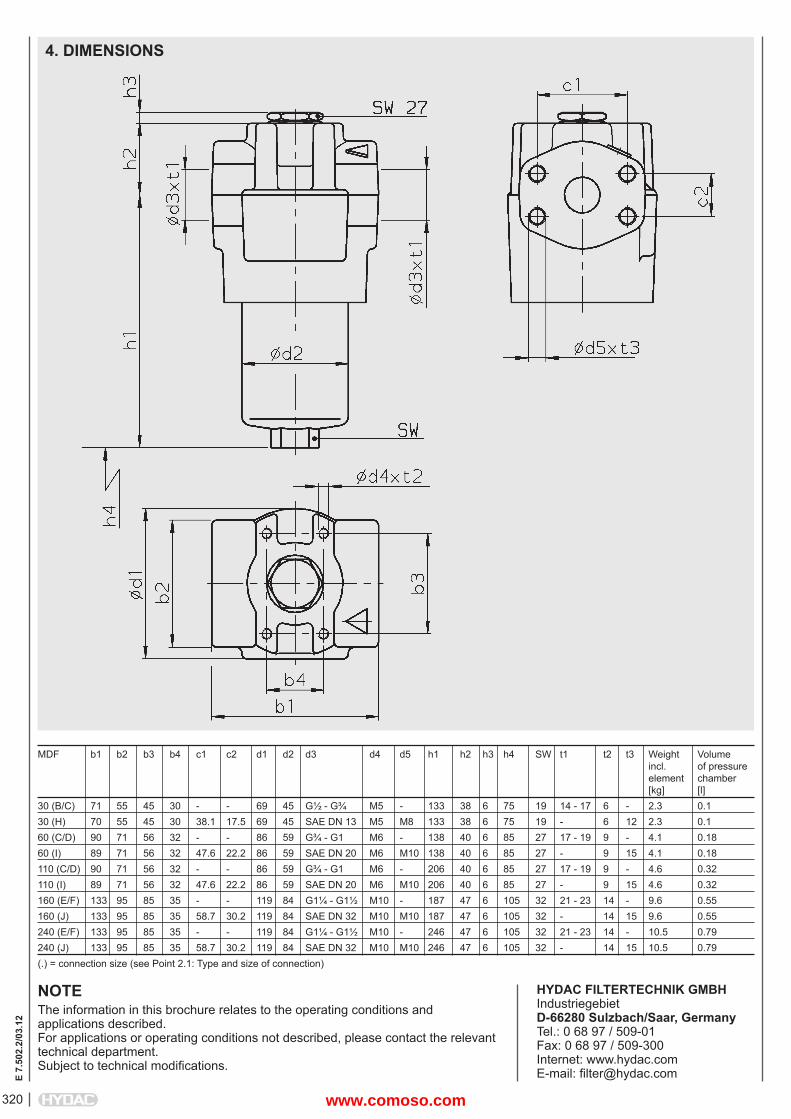
320
E 7.
502.
2/03
.12
NOTEThe information in this brochure relates to the operating conditions and applications described.For applications or operating conditions not described, please contact the relevant technical department. Subject to technical modifi cations.
HYDAC FILTERTECHNIK GMBHIndustriegebietD-66280 Sulzbach/Saar, GermanyTel.: 0 68 97 / 509-01Fax: 0 68 97 / 509-300Internet: www.hydac.comE-mail: fi [email protected]
MDF b1 b2 b3 b4 c1 c2 d1 d2 d3 d4 d5 h1 h2 h3 h4 SW t1 t2 t3 Weight Volume incl. of pressure element chamber [kg] [l]30 (B/C) 71 55 45 30 - - 69 45 G½ - G¾ M5 - 133 38 6 75 19 14 - 17 6 - 2.3 0.130 (H) 70 55 45 30 38.1 17.5 69 45 SAE DN 13 M5 M8 133 38 6 75 19 - 6 12 2.3 0.160 (C/D) 90 71 56 32 - - 86 59 G¾ - G1 M6 - 138 40 6 85 27 17 - 19 9 - 4.1 0.1860 (I) 89 71 56 32 47.6 22.2 86 59 SAE DN 20 M6 M10 138 40 6 85 27 - 9 15 4.1 0.18110 (C/D) 90 71 56 32 - - 86 59 G¾ - G1 M6 - 206 40 6 85 27 17 - 19 9 - 4.6 0.32110 (I) 89 71 56 32 47.6 22.2 86 59 SAE DN 20 M6 M10 206 40 6 85 27 - 9 15 4.6 0.32160 (E/F) 133 95 85 35 - - 119 84 G1¼ - G1½ M10 - 187 47 6 105 32 21 - 23 14 - 9.6 0.55160 (J) 133 95 85 35 58.7 30.2 119 84 SAE DN 32 M10 M10 187 47 6 105 32 - 14 15 9.6 0.55240 (E/F) 133 95 85 35 - - 119 84 G1¼ - G1½ M10 - 246 47 6 105 32 21 - 23 14 - 10.5 0.79240 (J) 133 95 85 35 58.7 30.2 119 84 SAE DN 32 M10 M10 246 47 6 105 32 - 14 15 10.5 0.79(.) = connection size (see Point 2.1: Type and size of connection)
4. DIMENSIONS
www.comoso.com
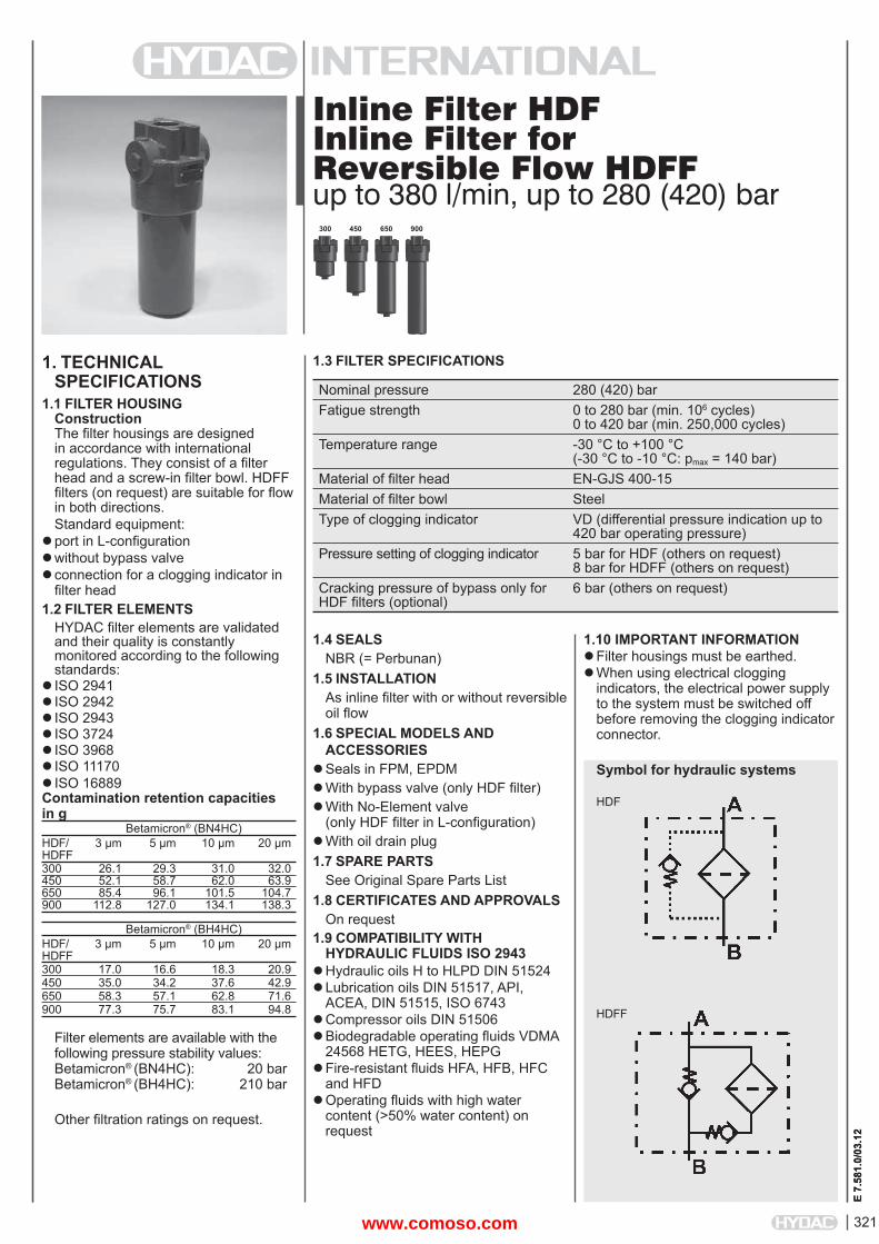
321
E 7.
581.
0/03
.12
Inline Filter HDFInline Filter for Reversible Flow HDFFup to 380 l/min, up to 280 (420) bar
1. TECHNICALSPECIFICATIONS
1.1 FILTER HOUSINGConstructionThe fi lter housings are designed in accordance with international regulations. They consist of a fi lter head and a screw-in fi lter bowl. HDFF fi lters (on request) are suitable for fl ow in both directions.Standard equipment:
port in L-confi gurationwithout bypass valve connection for a clogging indicator in fi lter head
1.2 FILTER ELEMENTSHYDAC fi lter elements are validated and their quality is constantly monitored according to the following standards:
ISO 2941ISO 2942ISO 2943ISO 3724ISO 3968ISO 11170ISO 16889Contamination retention capacities in g Betamicron® (BN4HC)HDF/ 3 μm 5 μm 10 μm 20 μmHDFF300 26.1 29.3 31.0 32.0450 52.1 58.7 62.0 63.9650 85.4 96.1 101.5 104.7900 112.8 127.0 134.1 138.3
Betamicron® (BH4HC)HDF/ 3 μm 5 μm 10 μm 20 μmHDFF300 17.0 16.6 18.3 20.9450 35.0 34.2 37.6 42.9650 58.3 57.1 62.8 71.6900 77.3 75.7 83.1 94.8
Filter elements are available with the following pressure stability values:Betamicron® (BN4HC): 20 barBetamicron® (BH4HC): 210 bar
Other fi ltration ratings on request.
1.10 IMPORTANT INFORMATION Filter housings must be earthed.When using electrical clogging
indicators, the electrical power supply to the system must be switched off before removing the clogging indicator connector.
1.3 FILTER SPECIFICATIONS
Symbol for hydraulic systems
300 650 900450
E 7.
581.
0/03
.12
1.4 SEALSNBR (= Perbunan)
1.5 INSTALLATIONAs inline fi lter with or without reversible oil fl ow
1.6 SPECIAL MODELS AND ACCESSORIES
Seals in FPM, EPDMWith bypass valve (only HDF fi lter)With No-Element valve
(only HDF fi lter in L-confi guration)With oil drain plug1.7 SPARE PARTS
See Original Spare Parts List1.8 CERTIFICATES AND APPROVALS
On request1.9 COMPATIBILITY WITH
HYDRAULIC FLUIDS ISO 2943Hydraulic oils H to HLPD DIN 51524Lubrication oils DIN 51517, API,
ACEA, DIN 51515, ISO 6743Compressor oils DIN 51506Biodegradable operating fl uids VDMA
24568 HETG, HEES, HEPGFire-resistant fl uids HFA, HFB, HFC
and HFDOperating fl uids with high water
content (>50% water content) on request
HDF
HDFF
Nominal pressure 280 (420) barFatigue strength 0 to 280 bar (min. 106 cycles)
0 to 420 bar (min. 250,000 cycles)Temperature range -30 °C to +100 °C
(-30 °C to -10 °C: pmax = 140 bar)Material of fi lter head EN-GJS 400-15Material of fi lter bowl SteelType of clogging indicator VD (differential pressure indication up to
420 bar operating pressure)Pressure setting of clogging indicator 5 bar for HDF (others on request)
8 bar for HDFF (others on request)Cracking pressure of bypass only for HDF fi lters (optional)
6 bar (others on request)
www.comoso.com
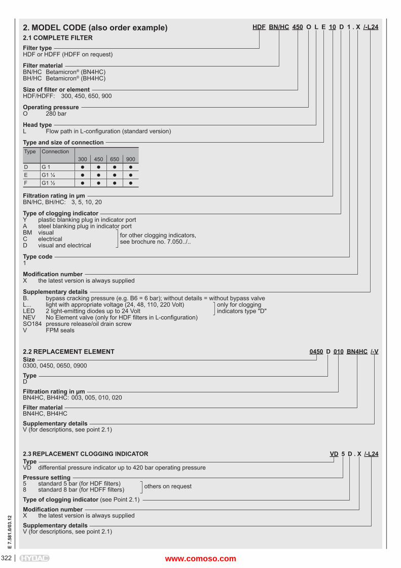
E 7.
581.
0/03
.12
322
0450 D 010 BN4HC /-VSize0300, 0450, 0650, 0900TypeDFiltration rating in μmBN4HC, BH4HC: 003, 005, 010, 020Filter materialBN4HC, BH4HCSupplementary detailsV (for descriptions, see point 2.1)
2.3 REPLACEMENT CLOGGING INDICATOR VD 5 D . X /-L24TypeVD differential pressure indicator up to 420 bar operating pressurePressure setting5 standard 5 bar (for HDF fi lters) others on request8 standard 8 bar (for HDFF fi lters)Type of clogging indicator (see Point 2.1)Modifi cation numberX the latest version is always suppliedSupplementary detailsV (for descriptions, see point 2.1)
HDF BN/HC 450 O L E 10 D 1 . X /-L24
Filter typeHDF or HDFF (HDFF on request)
Filter materialBN/HC Betamicron® (BN4HC)BH/HC Betamicron® (BH4HC)
Size of fi lter or elementHDF/HDFF: 300, 450, 650, 900
Operating pressureO 280 bar
Head typeL Flow path in L-confi guration (standard version)
Type and size of connectionType Connection
300 450 650 900D G 1
E G1 ¼
F G1 ½
Filtration rating in μmBN/HC, BH/HC: 3, 5, 10, 20
Type of clogging indicatorY plastic blanking plug in indicator portA steel blanking plug in indicator portBM visual for other clogging indicators,C electrical see brochure no. 7.050../..D visual and electrical
Type code1
Modifi cation numberX the latest version is always supplied
Supplementary detailsB. bypass cracking pressure (e.g. B6 = 6 bar); without details = without bypass valveL... light with appropriate voltage (24, 48, 110, 220 Volt) only for clogging LED 2 light-emitting diodes up to 24 Volt indicators type "D"NEV No Element valve (only for HDF fi lters in L-confi guration)SO184 pressure release/oil drain screwV FPM seals
2. MODEL CODE (also order example)2.1 COMPLETE FILTER
2.2 REPLACEMENT ELEMENT
www.comoso.com
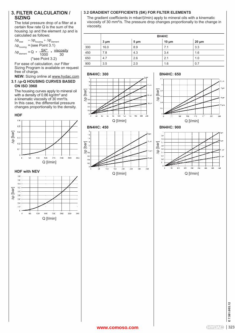
323
E 7.
581.
0/03
.12
3. FILTER CALCULATION /SIZINGThe total pressure drop of a fi lter at a certain fl ow rate Q is the sum of the housing p and the element p and is calculated as follows:ptotal phousingpelement
phousing = (see Point 3.1)
pelement = Q • SK* • viscosity 1000 30 (*see Point 3.2)For ease of calculation, our Filter Sizing Program is available on request free of charge.NEW: Sizing online at www.hydac.com
3.1 p-Q HOUSING CURVES BASED ON ISO 3968The housing curves apply to mineral oil with a density of 0.86 kg/dm³ and a kinematic viscosity of 30 mm²/s. In this case, the differential pressure changes proportionally to the density.
HDF
p [b
ar]
Q [l/min]
HDF with NEV
p [b
ar]
Q [l/min]
3.2 GRADIENT COEFFICIENTS (SK) FOR FILTER ELEMENTSThe gradient coeffi cients in mbar/(l/min) apply to mineral oils with a kinematic viscosity of 30 mm²/s. The pressure drop changes proportionally to the change in viscosity.
BH4HC3 μm 5 μm 10 μm 20 μm
300 16.0 8.9 7.1 3.3
450 7.8 4.3 3.4 1.6
650 4.7 2.6 2.1 1.0
900 3.5 2.0 1.6 0.7
p [b
ar]
Q [l/min]
BN4HC: 300
p [b
ar]
Q [l/min]
BN4HC: 450
p [b
ar]
Q [l/min]
BN4HC: 650
p [b
ar]
Q [l/min]
BN4HC: 900
www.comoso.com
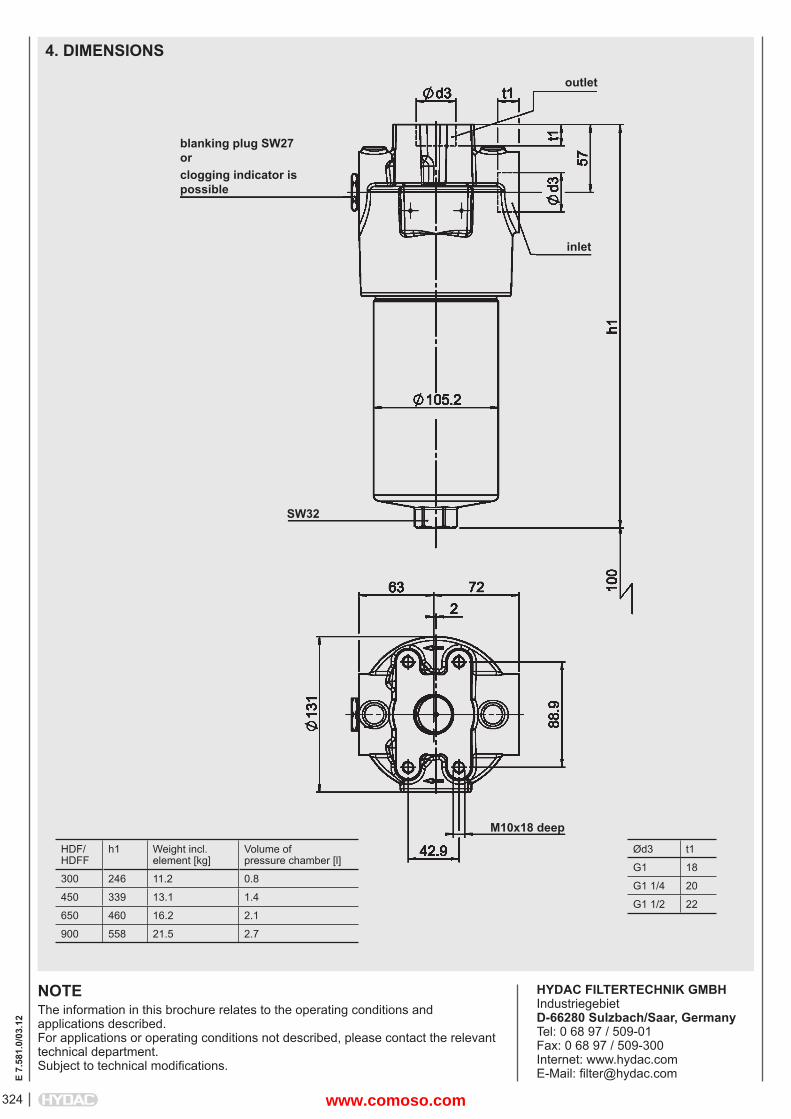
E 7.
581.
0/03
.12
324
NOTEThe information in this brochure relates to the operating conditions and applications described.For applications or operating conditions not described, please contact the relevant technical department. Subject to technical modifi cations.
HYDAC FILTERTECHNIK GMBHIndustriegebietD-66280 Sulzbach/Saar, GermanyTel: 0 68 97 / 509-01Fax: 0 68 97 / 509-300Internet: www.hydac.comE-Mail: fi [email protected]
HDF/HDFF
h1 Weight incl. element [kg]
Volume of pressure chamber [l]
300 246 11.2 0.8
450 339 13.1 1.4
650 460 16.2 2.1
900 558 21.5 2.7
4. DIMENSIONS
blanking plug SW27orclogging indicator is possible
outlet
inlet
SW32
M10x18 deep
Ød3 t1
G1 18
G1 1/4 20
G1 1/2 22
www.comoso.com
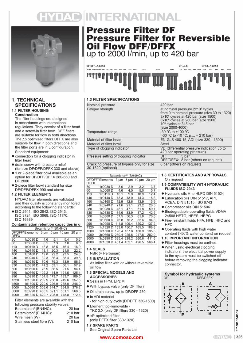
325
E 7.
501.
15/0
3.12
Pressure Filter DFPressure Filter for Reversible Oil Flow DFF/DFFXup to 2000 l/min, up to 420 bar
1. TECHNICALSPECIFICATIONS
1.1 FILTER HOUSINGConstructionThe fi lter housings are designed in accordance with international regulations. They consist of a fi lter head and a screw-in fi lter bowl. DFF fi lters are suitable for fl ow in both directions. The p optimized fi lters DFFX are also suitable for fl ow in both directions and the fi lter ports are in L confi guration.Standard equipment:
connection for a clogging indicator in fi lter head
drain screw with pressure relief(for size DF/DFF/DFFX 330 and above)
1 or 2-piece fi lter bowl available as an option for DF/DFF/DFFX 280-660 and DF 2000
2-piece fi lter bowl standard for size DF/DFF/DFFX 990 and above
1.2 FILTER ELEMENTSHYDAC fi lter elements are validated and their quality is constantly monitored according to the following standards:
ISO 2941, ISO 2942, ISO 2943, ISO 3724, ISO 3968, ISO 11170, ISO 16889
Contamination retention capacities in g Betamicron® (BN4HC)DF/DFF/ Elements 3 μm 5 μm 10 μm 20 μmDFFX30 1x0030 D 4.6 5.1 5.4 5.660 1x0060 D 6.5 7.3 7.8 8.0110 1x0110 D 13.8 15.5 16.4 16.9140 1x0140 D 18.1 20.3 21.5 22.2160 1x0160 D 19.8 22.2 23.5 24.3240 1x0240 D 32.3 36.3 38.4 39.6280 1x0280 D 70.6 79.3 83.9 86.6330 1x0330 D 47.2 53.1 56.1 57.9500 1x0500 D 76.9 86.5 91.5 94.4660 1x0660 D 102.2 114.9 121.5 125.4990 1x0990 D 154.5 173.7 183.7 189.51320 1x1320 D 209.9 236.0 249.6 257.51500 1x1500 D 220.0 226.0 238.0 246.02000 3x0660 D 306.6 344.7 364.5 376.23000 3x0990 D 463.5 521.1 551.1 568.54000 3x1320 D 629.7 708.0 748.8 772.5
Filter elements are available with the following pressure stability values:Betamicron® (BN4HC): 20 barBetamicron® (BH4HC): 210 barWire mesh (W): 20 barStainless steel fi bre (V): 210 bar
1.8 CERTIFICATES AND APPROVALSOn request
1.9 COMPATIBILITY WITH HYDRAULIC FLUIDS ISO 2943
Hydraulic oils H to HLPD DIN 51524Lubrication oils DIN 51517, API,
ACEA, DIN 51515, ISO 6743Compressor oils DIN 51506Biodegradable operating fl uids VDMA
24568 HETG, HEES, HEPGFire-resistant fl uids HFA, HFB, HFC and
HFDOperating fl uids with high water
content (>50% water content) on request1.10 IMPORTANT INFORMATIONFilter housings must be earthed.When using electrical clogging
indicators, the electrical power supply to the system must be switched off before removing the clogging indicatorconnector.
1.3 FILTER SPECIFICATIONS
Symbol for hydraulic systems
30 110140 160 240 280 330 500 660 990 1320 150060 2000 3000 4000
E 7.
501.
15/0
3.12
Betamicron® (BH4HC)DF/DFF/ Elements 3 μm 5 μm 10 μm 20 μmDFFX30 1x0030 D 3.0 2.9 3.2 3.760 1x0060 D 4.6 4.5 5.0 5.7110 1x0110 D 10.1 9.9 10.9 12.4140 1x0140 D 13.3 13.0 14.3 16.3160 1x0160 D 12.9 12.6 13.9 15.9240 1x0240 D 21.6 21.1 23.2 26.5280 1x0280 D 48.1 47.1 51.8 59.1330 1x0330 D 34.6 33.9 37.2 42.5500 1x0500 D 57.5 56.3 61.8 70.5660 1x0660 D 76.8 75.2 82.6 94.3990 1x0990 D 111.8 109.4 120.2 137.21320 1x1320 D 153.8 150.7 165.5 188.81500 1x1500 D 126.4 137.8 160.9 195.32000 3x0660 D 230.4 225.6 247.8 282.93000 3x0990 D 335.4 328.2 360.6 411.64000 3x1320 D 461.4 452.1 496.5 566.4
1.4 SEALSNBR (= Perbunan)
1.5 INSTALLATIONAs inline fi lter with or without reversible oil fl ow
1.6 SPECIAL MODELS AND ACCESSORIES
Seals in FPM, EPDMWith bypass valve (only DF fi lter)Oil drain screw, up to DF/DFF 280In ADI material
- for high duty cycle (DF/DFF 330-1500)Element top-removable -
TKZ 3.X (only DF fi lters 330 - 1320)P-optimized fi lter
(only DFFX fi lter 330-1320)1.7 SPARE PARTS
See Original Spare Parts List
DF DFF/DFFX
DF/DFF...1.X/2.X330 500 660 990 1320 330 500 660 990 1320
DF...3.X DFFX...1.X/2.X
Nominal pressure 420 barFatigue strength at nominal pressure 2x10⁶ cycles
from 0 to nominal pressure (size 30 to 1320)3x10⁵ cycles at 420 bar (size 1500)3x10⁶ cycles at 280 bar (size 1500)106 cycles at 315 bar (size 2000-4000)
Temperature range -30 °C to +100 °C(-30 °C to -10 °C: pmax = 210 bar)
Material of fi lter head EN-GJS 400-15, ADI (size 330 - 1500)Material of fi lter bowl SteelType of clogging indicator VD (differential pressure indication up to
420 bar operating pressure)Pressure setting of clogging indicator DF: 5 bar
DFF/DFFX: 8 bar (others on request)Cracking pressure of bypass only for size 30-1320 (optional)
6 bar (others on request)
www.comoso.com
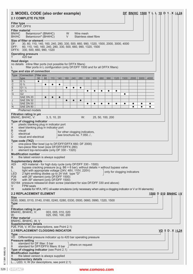
E 7.
501.
15/0
3.12
326
DF BN/HC 1500 T L L 10 D 1 . X /-L24
Filter typeDF, DFF, DFFXFilter materialBN/HC Betamicron® (BN4HC) W Wire meshBH/HC Betamicron® (BH4HC) V Stainless steel fi breSize of fi lter or elementDF: 30, 60, 110, 140, 160, 240, 280, 330, 500, 660, 990, 1320, 1500, 2000, 3000, 4000DFF: 60, 110, 140, 160, 240, 280, 330, 500, 660, 990, 1320, 1500DFFX: 330, 500, 660, 990, 1320Operating pressureT 420 barHead designno details inline fi lter ports (not possible for DFFX fi lters)L fi lter ports in L confi guration (only DF/DFF 1500 and for all DFFX fi lters)Type and size of connectionType Connection
typeFilter size
30 60 110 140 160 240 280 330 500 660 990 1320 1500 2000 3000 4000B G ½ C G ¾ E G1 ¼ F G1 ½ G G2 I SAE DN 20 J SAE DN 32 L SAE DN 50 N SAE DN 80 Preferred modelsFiltration rating in μmBN/HC, BH/HC, V: 3, 5, 10, 20 W: 25, 50, 100, 200Type of clogging indicatorY plastic blanking plug in indicator portA steel blanking plug in indicator portB visual for other clogging indicators,C electrical see brochure no. 7.050../..D visual and electricalType code (TKZ)1 one-piece fi lter bowl (up to DF/DFF/DFFX 660; DF 2000)2 two-piece fi lter bowl (size DF/DFF/DFFX 280)3 element top-removable (only DF 330 - 1320)Modifi cation numberX the latest version is always suppliedSupplementary detailsADI ADI material - for high duty cycle (only DF/DFF 330 - 1500)B. bypass cracking pressure (e.g. B6 = 6 bar); without details = without bypass valveL... light with appropriate voltage (24V, 48V, 110V, 220V) only for clogging indicatorsLED 2 light emitting diodes up to 24 Volt type "D"P26 with 26" element (only DF/DFF 1500)P39 with 39" element (only DF/DFF 1500)SO184 pressure release/oil drain screw (standard for size DF/DFF 330 and above)V FPM sealsW suitable for HFA, HFC oil-water emulsions (only necessary when using a clogging indicator or V or W elements)
2. MODEL CODE (also order example)2.1 COMPLETE FILTER
1500 D 010 BN4HC /-VSize0030, 0060, 0110, 0140, 0160, 0240, 0280, 0330, 0500, 0660, 0990, 1320, 1500TypeDFiltration rating in μmBN4HC, BH4HC, V: 003, 005, 010, 020W: 025, 050, 100, 200Filter materialBN4HC, BH4HC, W, VSupplementary detailsP26, P39, V, W (for descriptions, see Point 2.1)
2.2 REPLACEMENT ELEMENT
2.3 REPLACEMENT CLOGGING INDICATOR VD 5 D . X /-L24TypeVD Differential pressure indicator up to 420 bar operating pressurePressure setting5 standard for DF fi lter: 5 bar others on request8 standard for DFF/DFFX fi lters: 8 barType of clogging indicator (see Point 2.1)Modifi cation numberX the latest version is always suppliedSupplementary detailsL..., LED, V, W (for descriptions, see point 2.1)
www.comoso.com
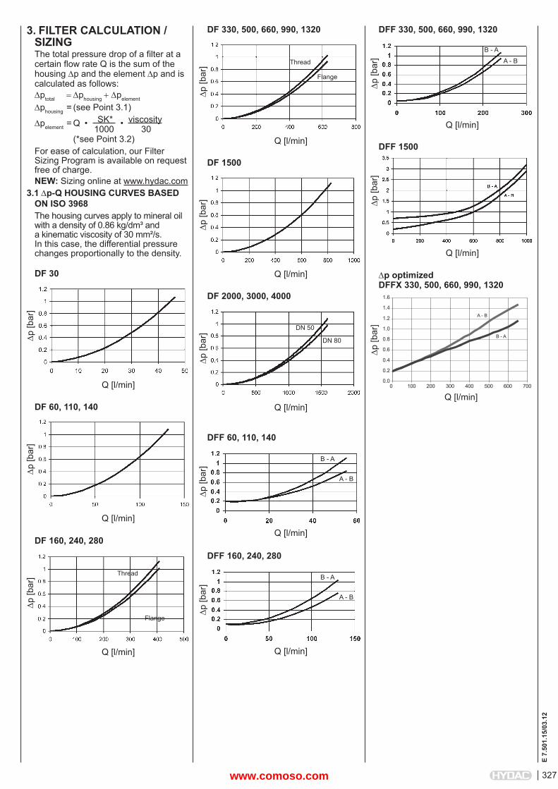
327
E 7.
501.
15/0
3.12
3. FILTER CALCULATION /SIZINGThe total pressure drop of a fi lter at a certain fl ow rate Q is the sum of the housing p and the element p and is calculated as follows:ptotal phousingpelement
phousing = (see Point 3.1)
pelement = Q • SK* • viscosity 1000 30 (*see Point 3.2)For ease of calculation, our Filter Sizing Program is available on request free of charge.NEW: Sizing online at www.hydac.com
3.1 p-Q HOUSING CURVES BASED ON ISO 3968The housing curves apply to mineral oil with a density of 0.86 kg/dm³ and a kinematic viscosity of 30 mm²/s. In this case, the differential pressure changes proportionally to the density.
DF 30
p [b
ar]
Q [l/min]
DF 60, 110, 140
p [b
ar]
Q [l/min]
DF 160, 240, 280
p [b
ar]
Q [l/min]
Thread
Flange
DF 330, 500, 660, 990, 1320
p [b
ar]
Q [l/min]
Thread
Flange
DF 1500
p [b
ar]
Q [l/min]
DF 2000, 3000, 4000
p [b
ar]
Q [l/min]
DN 50
DN 80
DFF 60, 110, 140
p [b
ar]
Q [l/min]
B - A
A - B
DFF 160, 240, 280
p [b
ar]
Q [l/min]
B - A
A - B
DFF 330, 500, 660, 990, 1320
p [b
ar]
Q [l/min]
B - A
A - B
DFF 1500
p [b
ar]
Q [l/min]
p optimizedDFFX 330, 500, 660, 990, 1320
p [b
ar]
Q [l/min]
0.0
0.2
0.4
0.6
0.8
1.0
1.2
1.4
1.6
0 100 200 300 400 500 600 700
A - B
B - A
www.comoso.com
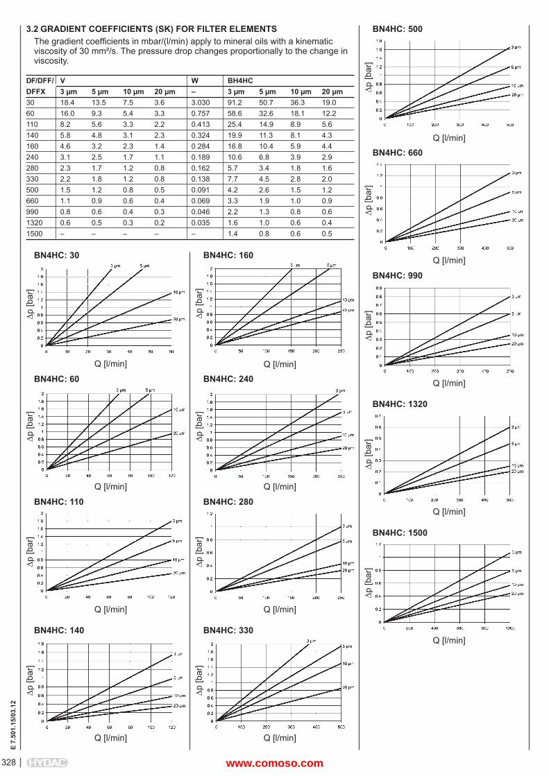
E 7.
501.
15/0
3.12
328
3.2 GRADIENT COEFFICIENTS (SK) FOR FILTER ELEMENTSThe gradient coeffi cients in mbar/(l/min) apply to mineral oils with a kinematic viscosity of 30 mm²/s. The pressure drop changes proportionally to the change in viscosity.
DF/DFF/ V W BH4HCDFFX 3 μm 5 μm 10 μm 20 μm – 3 μm 5 μm 10 μm 20 μm30 18.4 13.5 7.5 3.6 3.030 91.2 50.7 36.3 19.060 16.0 9.3 5.4 3.3 0.757 58.6 32.6 18.1 12.2110 8.2 5.6 3.3 2.2 0.413 25.4 14.9 8.9 5.6140 5.8 4.8 3.1 2.3 0.324 19.9 11.3 8.1 4.3160 4.6 3.2 2.3 1.4 0.284 16.8 10.4 5.9 4.4240 3.1 2.5 1.7 1.1 0.189 10.6 6.8 3.9 2.9280 2.3 1.7 1.2 0.8 0.162 5.7 3.4 1.8 1.6330 2.2 1.8 1.2 0.8 0.138 7.7 4.5 2.8 2.0500 1.5 1.2 0.8 0.5 0.091 4.2 2.6 1.5 1.2660 1.1 0.9 0.6 0.4 0.069 3.3 1.9 1.0 0.9990 0.8 0.6 0.4 0.3 0.046 2.2 1.3 0.8 0.61320 0.6 0.5 0.3 0.2 0.035 1.6 1.0 0.6 0.41500 – – – – – 1.4 0.8 0.6 0.5
p [b
ar]
Q [l/min]
BN4HC: 30
p [b
ar]
Q [l/min]
BN4HC: 60
p [b
ar]
Q [l/min]
BN4HC: 160
p [b
ar]
Q [l/min]
BN4HC: 240
p [b
ar]
Q [l/min]
BN4HC: 110
p [b
ar]
Q [l/min]
BN4HC: 140
p [b
ar]
Q [l/min]
BN4HC: 280
p [b
ar]
Q [l/min]
BN4HC: 330
p [b
ar]
Q [l/min]
BN4HC: 500
p [b
ar]
Q [l/min]
BN4HC: 660
p [b
ar]
Q [l/min]
BN4HC: 990
p [b
ar]
Q [l/min]
BN4HC: 1320
p [b
ar]
Q [l/min]
BN4HC: 1500
www.comoso.com
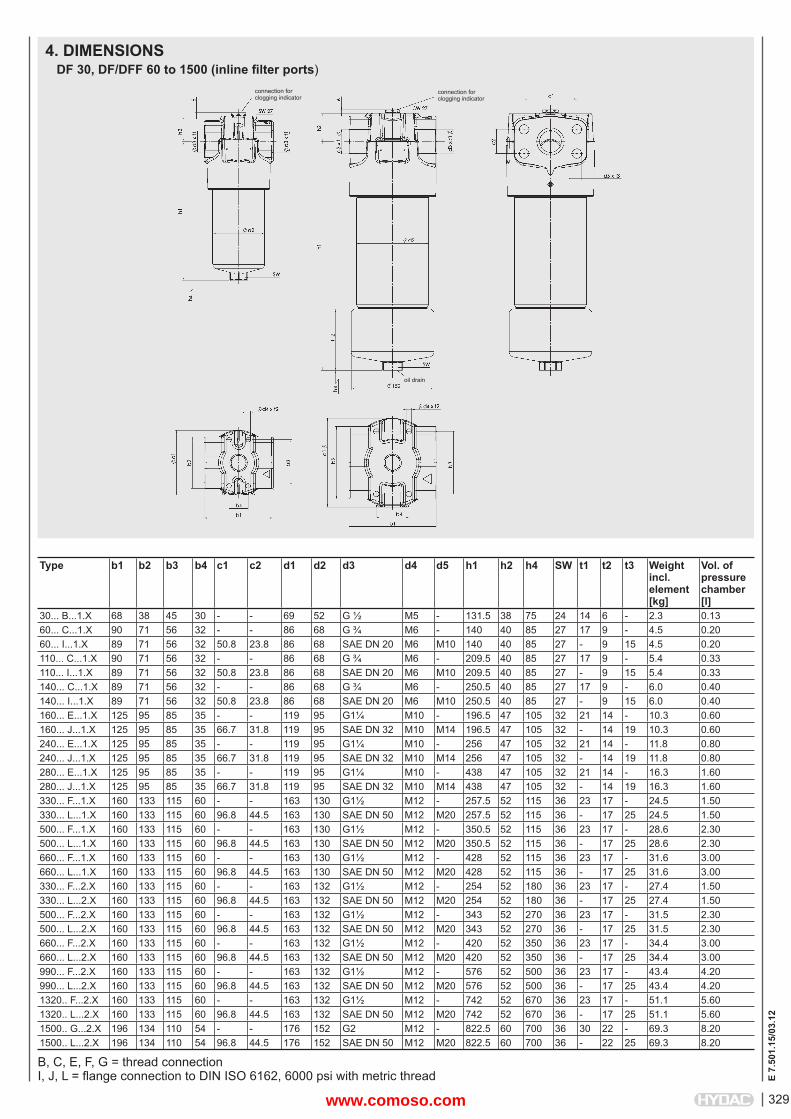
329
E 7.
501.
15/0
3.12
4. DIMENSIONSDF 30, DF/DFF 60 to 1500 (inline fi lter ports)
connection for clogging indicator
B, C, E, F, G = thread connectionI, J, L = fl ange connection to DIN ISO 6162, 6000 psi with metric thread
connection for clogging indicator
oil drain
Type b1 b2 b3 b4 c1 c2 d1 d2 d3 d4 d5 h1 h2 h4 SW t1 t2 t3 Weightincl. element[kg]
Vol. of pressure chamber [l]
30... B...1.X 68 38 45 30 - - 69 52 G ½ M5 - 131.5 38 75 24 14 6 - 2.3 0.1360... C...1.X 90 71 56 32 - - 86 68 G ¾ M6 - 140 40 85 27 17 9 - 4.5 0.2060... I...1.X 89 71 56 32 50.8 23.8 86 68 SAE DN 20 M6 M10 140 40 85 27 - 9 15 4.5 0.20110... C...1.X 90 71 56 32 - - 86 68 G ¾ M6 - 209.5 40 85 27 17 9 - 5.4 0.33110... I...1.X 89 71 56 32 50.8 23.8 86 68 SAE DN 20 M6 M10 209.5 40 85 27 - 9 15 5.4 0.33140... C...1.X 89 71 56 32 - - 86 68 G ¾ M6 - 250.5 40 85 27 17 9 - 6.0 0.40140... I...1.X 89 71 56 32 50.8 23.8 86 68 SAE DN 20 M6 M10 250.5 40 85 27 - 9 15 6.0 0.40160... E...1.X 125 95 85 35 - - 119 95 G1¼ M10 - 196.5 47 105 32 21 14 - 10.3 0.60160... J...1.X 125 95 85 35 66.7 31.8 119 95 SAE DN 32 M10 M14 196.5 47 105 32 - 14 19 10.3 0.60240... E...1.X 125 95 85 35 - - 119 95 G1¼ M10 - 256 47 105 32 21 14 - 11.8 0.80240... J...1.X 125 95 85 35 66.7 31.8 119 95 SAE DN 32 M10 M14 256 47 105 32 - 14 19 11.8 0.80280... E...1.X 125 95 85 35 - - 119 95 G1¼ M10 - 438 47 105 32 21 14 - 16.3 1.60280... J...1.X 125 95 85 35 66.7 31.8 119 95 SAE DN 32 M10 M14 438 47 105 32 - 14 19 16.3 1.60330... F...1.X 160 133 115 60 - - 163 130 G1½ M12 - 257.5 52 115 36 23 17 - 24.5 1.50330... L...1.X 160 133 115 60 96.8 44.5 163 130 SAE DN 50 M12 M20 257.5 52 115 36 - 17 25 24.5 1.50500... F...1.X 160 133 115 60 - - 163 130 G1½ M12 - 350.5 52 115 36 23 17 - 28.6 2.30500... L...1.X 160 133 115 60 96.8 44.5 163 130 SAE DN 50 M12 M20 350.5 52 115 36 - 17 25 28.6 2.30660... F...1.X 160 133 115 60 - - 163 130 G1½ M12 - 428 52 115 36 23 17 - 31.6 3.00660... L...1.X 160 133 115 60 96.8 44.5 163 130 SAE DN 50 M12 M20 428 52 115 36 - 17 25 31.6 3.00330... F...2.X 160 133 115 60 - - 163 132 G1½ M12 - 254 52 180 36 23 17 - 27.4 1.50330... L...2.X 160 133 115 60 96.8 44.5 163 132 SAE DN 50 M12 M20 254 52 180 36 - 17 25 27.4 1.50500... F...2.X 160 133 115 60 - - 163 132 G1½ M12 - 343 52 270 36 23 17 - 31.5 2.30500... L...2.X 160 133 115 60 96.8 44.5 163 132 SAE DN 50 M12 M20 343 52 270 36 - 17 25 31.5 2.30660... F...2.X 160 133 115 60 - - 163 132 G1½ M12 - 420 52 350 36 23 17 - 34.4 3.00660... L...2.X 160 133 115 60 96.8 44.5 163 132 SAE DN 50 M12 M20 420 52 350 36 - 17 25 34.4 3.00990... F...2.X 160 133 115 60 - - 163 132 G1½ M12 - 576 52 500 36 23 17 - 43.4 4.20990... L...2.X 160 133 115 60 96.8 44.5 163 132 SAE DN 50 M12 M20 576 52 500 36 - 17 25 43.4 4.201320.. F...2.X 160 133 115 60 - - 163 132 G1½ M12 - 742 52 670 36 23 17 - 51.1 5.601320.. L...2.X 160 133 115 60 96.8 44.5 163 132 SAE DN 50 M12 M20 742 52 670 36 - 17 25 51.1 5.601500.. G...2.X 196 134 110 54 - - 176 152 G2 M12 - 822.5 60 700 36 30 22 - 69.3 8.201500.. L...2.X 196 134 110 54 96.8 44.5 176 152 SAE DN 50 M12 M20 822.5 60 700 36 - 22 25 69.3 8.20
www.comoso.com
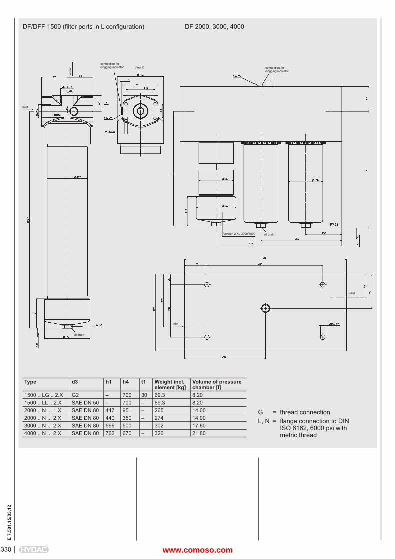
E 7.
501.
15/0
3.12
330
connection for clogging indicator
DF 2000, 3000, 4000DF/DFF 1500 (fi lter ports in L confi guration)
G = thread connectionL, N = fl ange connection to DIN ISO 6162, 6000 psi with metric thread
outle
t
inlet
View X connection for clogging indicator
Version 2.X / 3000/4000 oil drain
outlet
inlet
oil drain
Type d3 h1 h4 t1 Weight incl. element [kg]
Volume of pressure chamber [l]
1500 .. LG .. 2.X G2 – 700 30 69.3 8.201500 .. LL .. 2.X SAE DN 50 – 700 – 69.3 8.202000 .. N ... 1.X SAE DN 80 447 95 – 265 14.002000 .. N ... 2.X SAE DN 80 440 350 – 274 14.003000 .. N ... 2.X SAE DN 80 596 500 – 302 17.604000 .. N ... 2.X SAE DN 80 762 670 – 326 21.80
www.comoso.com
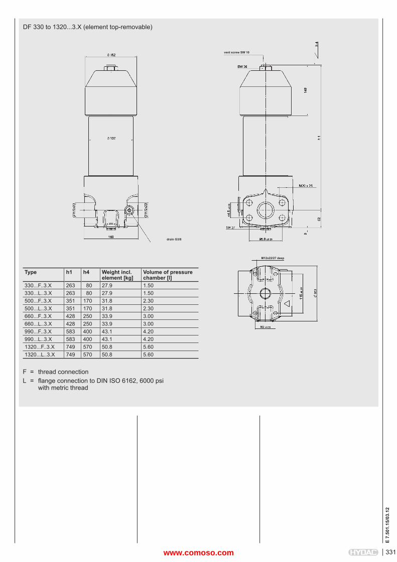
331
E 7.
501.
15/0
3.12
DF 330 to 1320...3.X (element top-removable)
Type h1 h4 Weight incl. element [kg]
Volume of pressure chamber [l]
330...F..3.X 263 80 27.9 1.50330...L..3.X 263 80 27.9 1.50500...F..3.X 351 170 31.8 2.30500...L..3.X 351 170 31.8 2.30660...F..3.X 428 250 33.9 3.00660...L..3.X 428 250 33.9 3.00990...F..3.X 583 400 43.1 4.20990...L..3.X 583 400 43.1 4.201320...F..3.X 749 570 50.8 5.601320...L..3.X 749 570 50.8 5.60
drain G3/8
M12x22/27 deep
vent screw SW 10
F = thread connectionL = fl ange connection to DIN ISO 6162, 6000 psi with metric thread
www.comoso.com
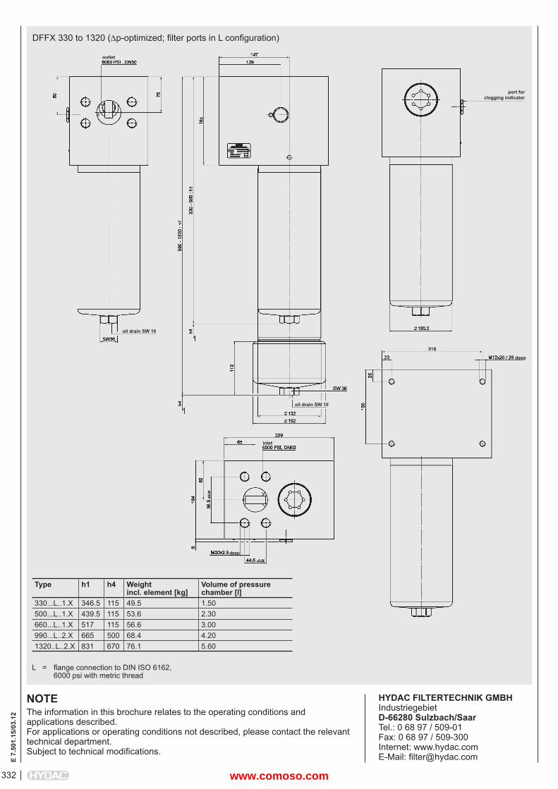
E 7.
501.
15/0
3.12
332
NOTEThe information in this brochure relates to the operating conditions and applications described.For applications or operating conditions not described, please contact the relevant technical department. Subject to technical modifi cations.
HYDAC FILTERTECHNIK GMBHIndustriegebietD-66280 Sulzbach/SaarTel.: 0 68 97 / 509-01Fax: 0 68 97 / 509-300Internet: www.hydac.comE-Mail: fi [email protected]
DFFX 330 to 1320 (p-optimized; fi lter ports in L confi guration)
Type h1 h4 Weightincl. element [kg]
Volume of pressure chamber [l]
330...L..1.X 346.5 115 49.5 1.50500...L..1.X 439.5 115 53.6 2.30660...L..1.X 517 115 56.6 3.00990...L..2.X 665 500 68.4 4.201320..L..2.X 831 670 76.1 5.60
oil drain SW 10
L = fl ange connection to DIN ISO 6162, 6000 psi with metric thread
outlet
port forclogging indicator
oil drain SW 10
inlet
deep
deep
www.comoso.com