Embed Size (px)
Citation preview

High-Power Multi-Channel Amplifier
Quick Start Guide
Features• 4 Channel Amplifier with AccuBASS® Processing
• Configurable as 4/3/2 channels
• 4 x 200 W @ 2 ohms, 125 W @ 4 ohms, 2 x 400 W bridged
• High Current Design
• 4 RCA Line Inputs
• 2 RCA Line Outputs
• 6 Summable Speaker-Level Inputs for OEM integration
• MILCTM Level Matching Technology (Patent pending)
• GTOTM Signal Sense (Great Turn On)
• Independent 12 dB Linkwitz-Riley Crossovers
• Optional ACR-1 Dash Remote
• Solid and Rugged Chassis
• Minty

2
Quick Start Guide
Important Safety Instructions1. Read these instructions. 2. Keep these instructions.3. Heed all warnings.4. Follow all instructions.5. Do not use this apparatus near water.6. Clean only with a dry cloth.7. Do not block any ventilation openings. Install in accordance with the
manufacturer’s instructions.8. Do not install near any heat sources such as mufflers, silencers, exhaust
pipes, or other apparatus (including amplifiers) that produce heat.9. WARNING: Improper installation may lead to permanent injury or death.
Installation of the apparatus must be done with great care by qualified personnel, to prevent damage to fuel lines, power, and other electrical wiring, hydraulic brake lines, and other systems, that might compromise vehicle safety.
10. Provide +12V and Ground insulated wiring of 8 to 3 AWG to ensure adequate current to the amplifier.
11. Use rubber grommets to protect wiring whenever passing wires through metal openings or bulkheads.
12. Only use attachments/accessories specified by the manufacturer.13. Refer all servicing to qualified service personnel. Servicing is required
when the apparatus has been damaged in any way, such as the power in-put terminals are damaged, liquid has been spilled or objects have fallen into the apparatus, the apparatus has been exposed to rain or moisture, does not operate normally, or has been dropped.
14. This apparatus shall not be exposed to dripping or splashing, and no object filled with liquids, shall be placed on the apparatus.
15. Fuses shall be replaced only with the correct type and fuse value, and only when the apparatus is powered off.
16. Exposure to high sound pressure levels may lead to permanent hearing loss. Take every precaution to protect your hearing.
The lightning flash with arrowhead symbol within an equilateral triangle is intended to alert the user to the presence of uninsulated “dangerous voltage” within the product’s enclosure, that may be of sufficient magnitude to constitute a risk of electric shock to persons.The exclamation point within an equilateral triangle is intended to alert the user of the presence of important operating and mainte-nance (servicing) instructions in the literature accompanying the appliance.
Caution: to reduce the risk of electric shock, do not disassemble the apparatus, other than to remove the top panel to access the controls. There are no user-serviceable parts inside. Refer servicing to qualified personnel.
Recycling notice: If the time comes and this apparatus has fulfilled its destiny, do not throw it out into the trash. It has to be carefully recycled for the good of mankind, by a facility specially equipped for the safe recycling of electronic apparatii. Please contact your local or state recycling leaders for assistance in locating a suitable nearby recycling facility. Or, contact us and we might be able to repair it for you.

3
1. Fuses 40A – Replace these fuses only with the exact same style and Ampere rating. Disconnect 12V power before changing or inspecting the fuses.
2. Power Input Terminal +12V – This screw terminal connects to the +12V battery binding post of the vehicle. Use quality insulated wire, 8 to 3 AWG.
3. Remote Power Input Terminal – This screw terminal connects to the 12V remote trigger output of some head units. When the head unit is turned on, then the LC-4.800 will turn on.
4. Power Input Terminal Ground – This screw terminal connects to a good ground connection on the vehicle. Use quality insulated wire, gauge 8 to 3 AWG.
5. RCA Analog Line-Level Inputs – The line-level output from the head unit or factory-installed radios can connect here, so the LC-4.800 amplifier will receive the line-level audio signals. Do not use these inputs if you are using the speaker-level inputs.
6. RCA Analog Line-Level Outputs – The line-level output can connect to external amplifiers or subwoofer amplifiers.
7. Speaker-Level Inputs – The speaker-level output from amplifiers and factory installed radios can connect here. Do not use these inputs if you are using the RCA line-level inputs.
8. Remote Control Connector – This connects to the ACR-1 remote level control.
9. Speaker-Level Output Terminals – These screw terminals connect with speaker wire to your loudspeakers Make sure that the average combined speaker impedance does not dip below 2 Ohms, or 4 Ohms in bridged mono mode.
Connection Panel Features
1 2 3 4 5 6 8 97

4
Quick Start Guide
Control Panel Features
10 11 12 16 1713 14 15 18 19 20 14 21 15 16 17 22 23

5
10. Power LED – If you have connected your battery power, vehicle ground, and turn-on lead (or GTO signal sensing) correctly, then this light should be green to indicate the power is ON.
11. Protection LED – The amplifier has built-in diagnostic codes to tell you exactly what is going wrong should the amplifier detect a problem. See specifications page 11 for a list of diagnostic codes.
12. GTO Signal Sense – In the ON position, the LC-4.800 amplifier will turn on gracefully when it detects an incoming audio signal, and it will turn off after a period of time when the audio signal fades away to silence. Turn this OFF if using the remote power terminal (see item 3 above) turn on method.
13. Front High Level – Adjusts the Front High speaker-level input levels, to achieve a nice balance in levels.
14. AccuBASS®/ACR-1 – Enables/disables the AccuBASS® circuit and the ACR-1 remote level control. If enabled, ACR-1 controls the level of the level of the main outputs and line outputs. If disabled, then it just controls the line outputs (to a subwoofer for example)
The AccuBASS® has its own controls to work wonders on the lower bass of the main outputs and line outputs.
15. HP Crossover Frequency – Selects the 30 Hz to 300 Hz crossover point to match your speakers and system. The crossover for chan-nels 1/2 is high-pass only; the crossover for channels 3/4 can be selected as high-pass or low-pass.
16. Mono/Stereo – Amplifiers 1 and 2 can be joined in mono to pow-er a single more powerful speaker (4 Ohm minimum). Similarly for amplifiers 3 and 4. For example, 1/2 can be stereo, 3/4 mono.
17. Gain Control – Adjusts the overall output levels.
18. AccuBASS® Threshold – Selects the level at which the AccuBASS® will begin to work.
19. AccuBASS® Level – Adjusts the level of the AccuBASS®.
20. Front/Rear Bus Sum – This sums the front and rear inputs togeth-er. So two inputs (L/R) can feed four outputs (2L/2R).
21. Crossover Type LP/HP – The crossover of channels 3/4 can be selected as a high-pass or low-pass type. Super for bi-amping your speakers, with channels 1/2 high pass, and channels 3/4 low pass.
22. MILC™ Source Clip LED – The MILC™ (Maximum Input Level Control) patent-pending level-setting circuit prevents clipping and damaging distortion. It calculates when the waveform of an incoming audio signal is clipping, and if it is, this LED will fulfill its prime objective and shine forth.
With this advanced feature, you are able to optimize the level of the incoming audio signal until the Source Clip LED is just-prior to lighting. If the LED comes on during normal operation, you should adjust the level of the audio signals before they reach the LC-4.800.
23. Gain Maximized LEDs – These LEDs indicate when the LC-4.800 amplifier gain for channels 1/2 and 3/4 has been maximized for optimum performance.

6
Quick Start Guide
Quick StartHere are a few general steps to get your LC-4.800 amplifier up and running:
1. Undo the +12V and Ground connections to the car battery before making any connections to the amplifier.
2. Pick a mounting location that will provide access to the controls and connections, provide adequate ventilation, and also protect the amplifier from heat, moisture, and dirt. Make sure the ven-tilation slots on the sides are not blocked, and that the heatsink fins are not covered.
3. The LC-4.800 amplifier needs to be securely mounted using the four mounting holes located in each corner.
4. Before drilling any holes, take every precaution to prevent any damage to fuel lines, power and other electrical wir-
ing, hydraulic brake lines, and other systems, that might compro-mise vehicle safety.
5. When making connections, designate red RCA plugs as right, and designate white, black, or grey plugs as left. This is a good idea for consistency.
6. Use quality interconnect cables.
7. Connect the +12V input terminal of the unit to the +12V termi-nal of the vehicle battery, using 8 to 3 AWG.
8. Connect the Ground terminal of the unit to the chassis of the vehicle, using the same wire gauge as the +12V power wire.
9. Connect the remote power terminal of the unit to the remote turn-on switch of your source unit. Alternatively, you can skip this connection and use the GTO Signal sensing.
10. Connect your audio inputs to the unit – either speaker-level or line-level RCA… not both.
11. Run the ACR-1 remote to the front of the vehicle to adjust the level on the fly.
12. Connect your loudspeakers (2 Ohm stereo, 4 Ohm Bridged mini-mum load).
13. When all connections are made, reconnect the vehicle battery.
14. Adjust your input source gain using the MILC Source Clip LED. This will indicate if the incoming audio signals are clipping.
15. Set the LC-4.800 crossovers to the frequency recommended by the loudspeaker manufacturer.
16. Adjust the LC-4.800 AccuBass controls to suit. The ACR-1 adjusts the overall output level.
17. Enjoy the drive!
7
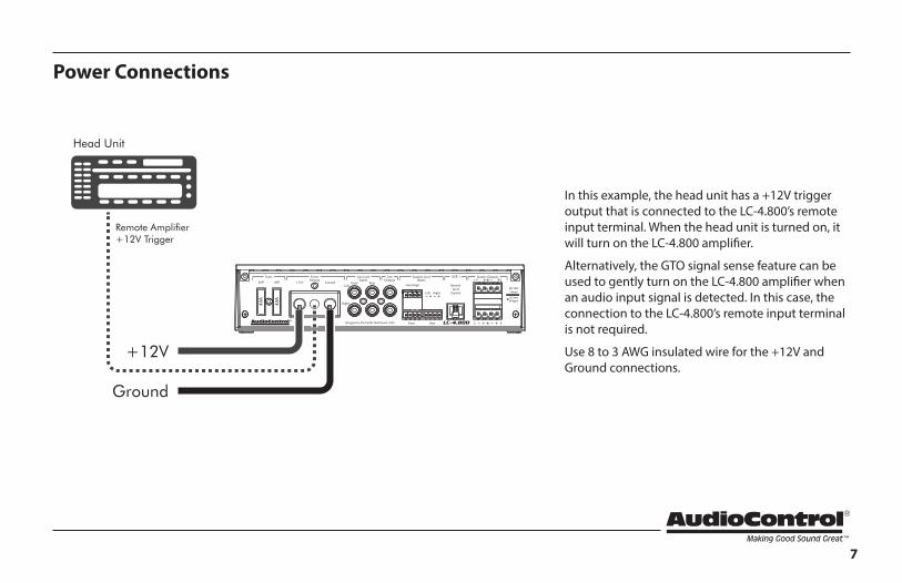
Power Connections
In this example, the head unit has a +12V trigger output that is connected to the LC-4.800’s remote input terminal. When the head unit is turned on, it will turn on the LC-4.800 amplifier.
Alternatively, the GTO signal sense feature can be used to gently turn on the LC-4.800 amplifier when an audio input signal is detected. In this case, the connection to the LC-4.800’s remote input terminal is not required.
Use 8 to 3 AWG insulated wire for the +12V and Ground connections.
Ground
Head Unit
Remote Amplifier+12V Trigger
+12V
8
Quick Start Guide
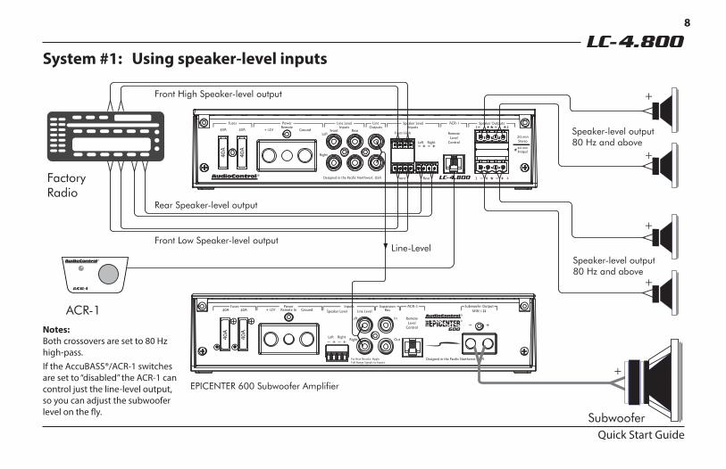
System #1: Using speaker-level inputs
Notes:Both crossovers are set to 80 Hz high-pass.If the AccuBASS®/ACR-1 switches are set to “disabled” the ACR-1 can control just the line-level output, so you can adjust the subwoofer level on the fly.
FactoryRadio
Front High Speaker-level output
Speaker-level output80 Hz and above
Speaker-level output80 Hz and above
Front Low Speaker-level outputLine-Level
EPICENTER 600 Subwoofer Amplifier
Rear Speaker-level output
+
+
+
+
ACR-1
Subwoofer
+
9
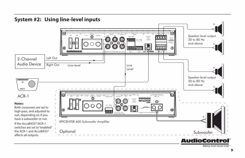
System #2: Using line-level inputs
2-ChannelAudio Device Line-level
Left Out
Right Out
Speaker-level output30 to 80 Hzand above
Speaker-level output30 to 80 Hzand above
LineLevel
EPICENTER 600 Subwoofer Amplifier
Optional
+
+
+
+
ACR-1
Subwoofer
+
Notes:Both crossovers are set to high-pass, and adjusted to suit, depending on if you have a subwoofer or not.If the AccuBASS®/ACR-1 switches are set to “enabled” the ACR-1 and AccuBASS® affects all outputs.

10
Quick Start Guide
ACR-1 Dash Control InstallationThe AudioControl ACR-1 dash control is a remote level for your LC-4.800 amplifier. It may be mounted under the dash using its own enclosure, or through a custom hole in the dash. The knob should be within reach of the driver, and in a spot where the LED is plainly visible. Disconnect the vehicle battery +12V and Ground connections before installation.
Dash Bracket Installation: The dash control mounts with four screws, which attach to the underside of the dashboard. Slide under the dash and place the dash control in its mounting po-sition, mark the best mounting holes, carefully drill pilot holes, and secure with screws.
Custom Installation: For that custom, finished look, the dash control can be flush-mounted directly on the dashboard (or anywhere else). Disassemble the ACR-1 from its enclosure.
Top Lid RemovalThe top lid must be removed to gain access to the controls, and then put back on again to protect the controls from dust bunnies.
Removal Procedure
1. Locate the two screws that hold the straight edge of the lid onto the connector side of the amplifier.
2. Use the supplied hex key to loosen both screws just enough until this edge of the lid can lift freely up just a little. (There is no need to remove the screws all the way, in case you lose them.)
3. Slide the lid toward the heatsink fins just a tad, before further lifting the straight edge of the lid about 2”, then disengage the remaining two points of contact (under the wavy edge).
4. Place the lid in a safe and handy place, ready for the time when you have finished adjusting the controls to your immense satis-faction, and just before Chivers brings tea and sandwiches.
11
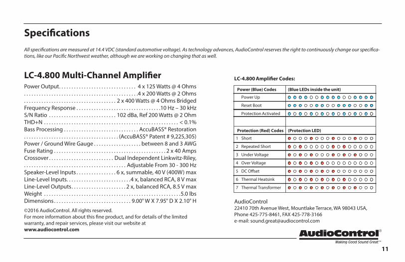
SpecificationsAll specifications are measured at 14.4 VDC (standard automotive voltage). As technology advances, AudioControl reserves the right to continuously change our specifica-tions, like our Pacific Northwest weather, although we are working on changing that as well.
LC-4.800 Multi-Channel AmplifierPower Output. . . . . . . . . . . . . . . . . . . . . . . . . . . . . . . 4 x 125 Watts @ 4 Ohms. . . . . . . . . . . . . . . . . . . . . . . . . . . . . . . . . . . . . . . . . . . . . .4 x 200 Watts @ 2 Ohms. . . . . . . . . . . . . . . . . . . . . . . . . . . . . . . . . . . . . 2 x 400 Watts @ 4 Ohms BridgedFrequency Response . . . . . . . . . . . . . . . . . . . . . . . . . . . . . . . . . .10 Hz – 30 kHzS/N Ratio . . . . . . . . . . . . . . . . . . . . . . . . . . . 102 dBa, Ref 200 Watts @ 2 OhmTHD+N . . . . . . . . . . . . . . . . . . . . . . . . . . . . . . . . . . . . . . . . . . . . . . . . . . . . . . < 0.1%Bass Processing . . . . . . . . . . . . . . . . . . . . . . . . . . . . . . AccuBASS® Restoration. . . . . . . . . . . . . . . . . . . . . . . . . . . . . . . . . . . . . . (AccuBASS® Patent # 9,225,305)Power / Ground Wire Gauge . . . . . . . . . . . . . . . . . . . between 8 and 3 AWGFuse Rating . . . . . . . . . . . . . . . . . . . . . . . . . . . . . . . . . . . . . . . . . . . . . 2 x 40 AmpsCrossover . . . . . . . . . . . . . . . . . . . . . . . . . . Dual Independent Linkwitz-Riley,. . . . . . . . . . . . . . . . . . . . . . . . . . . . . . . . . . . . . . . . . Adjustable From 30 - 300 HzSpeaker-Level Inputs . . . . . . . . . . . . . . . . 6 x, summable, 40 V (400W) maxLine-Level Inputs. . . . . . . . . . . . . . . . . . . . . . . . . .4 x, balanced RCA, 8 V maxLine-Level Outputs. . . . . . . . . . . . . . . . . . . . . . 2 x, balanced RCA, 8.5 V maxWeight . . . . . . . . . . . . . . . . . . . . . . . . . . . . . . . . . . . . . . . . . . . . . . . . . . . . . . .5.0 lbsDimensions . . . . . . . . . . . . . . . . . . . . . . . . . . . . . . . 9.00" W X 7.95" D X 2.10" H
©2016 AudioControl. All rights reserved.For more information about this fine product, and for details of the limited warranty, and repair services, please visit our website at www.audiocontrol.com
6
7
3
1
2
4
5
Thermal Heatsink
Thermal Transformer
Under Voltage
Short
Power Up
Reset Boot
Protection Activated
Repeated Short
Over Voltage
DC O�set
LC-4.800 Ampli�er Codes:
Protection (Red) Codes (Protection LED)
Power (Blue) Codes (Blue LEDs inside the unit)
AudioControl22410 70th Avenue West, Mountlake Terrace, WA 98043 USA, Phone 425-775-8461, FAX 425-778-3166 e-mail: [email protected]

12
Quick Start Guide PN 915-004-0 Rev A
Block Diagram
ActiveSpeaker Level
Conversion
ActiveSpeaker Level
Conversion
ActiveSpeaker Level
Conversion
Level
Remote LevelFront / Rear
Bus Combine
Variable LP/HPCrossover
Gain
AccuBASS& ACR-1
+-
-+
Right
Left
SpeakerOutputs
SpeakerOutputs
LineOutputs
Bridged
ACR-1 RemoteLevel Control
Speaker LevelRear
Line Level Rear
Line Level Front
Speaker LevelFront
Speaker LevelFront High
Inputs
Gain
MILCLevel Matching
GTOSignal Sense
TM
TM
Variable HPCrossover
+-
-+ 1
2
3
4
Bridged
Mono/Stereo
Mono/Stereo
AccuBASS
Right
Left
Right
Left
AccuBASS& ACR-1
Power Amplifiers 2 x 200 W @ 2 ohm
Power Amplifiers 2 x 200 W @ 2 ohm
Rear BusFront Bus
Here of Old wasThrain, King under
the Mountain