Embed Size (px)
Citation preview

SAND2010-1405P Supersedes SAND2003-1071P
Unlimited Release
FEDERAL RADIOLOGICAL MONITORING AND ASSESSMENT CENTER
FRMAC ASSESSMENT MANUAL VOLUME 1
OVERVIEW AND METHODS
The Federal Manual for Assessing Environmental
Data During a Radiological Emergency
September, 2010

Prepared by Sandia National Laboratories Albuquerque, New Mexico 87185 and Livermore, California 94550 Sandia National Laboratories is a multi-program laboratory managed and operated by Sandia Corporation, a wholly owned subsidiary of Lockheed Martin Corporation, for the US Department of Energy’s National Nuclear Security Administration under Contract DE-AC04-94AL85000. Approved for public release: further dissemination unlimited.
FRMAC Assessment Manual
Overview and Methods
Volume 1
Terrence D. Kraus
Assessment Work Group Co-Chair Sandia National Laboratories
Arthur Shanks, Jr.
Derivative Classifier Assessment Working Group Co-Chair
Sandia National Laboratories
Colleen T. O’Laughlin
Program Manager for CM/FRMAC Program DOE/NNSA
Daniel J. Blumenthal
Consequence Management Program Manager DOE/NNSA
Deborah A. Wilber
Director, Office of Emergency Response DOE/NNSA
This work was supported by the U.S. Department of Energy, National Nuclear Security Administration Nevada Operations Office, under Contract No. DE-AC08-96NV11718. FRMAC is an acronym for Federal Radiological Monitoring and Assessment Center.
DISCLAIMER
This report was prepared as an account of work sponsored by an agency of the United States Government. Neither the United States Government nor any agency thereof, nor any of their employees, nor any of their contractors, subcontractors or their employees, makes any warranty, express or implied, or assumes any legal liability or responsibility for the accuracy, completeness, or any third party’s use or the results of such use of any information, apparatus, product, or process disclosed, or represents that its use would not infringe privately owned rights. Reference herein to any specific commercial product, process, or service by trade name, trademark, manufacturer, or otherwise, does not necessarily constitute or imply its endorsement, recommendation, or favoring by the United States Government or any agency thereof or its contractors or subcontractors. The views and opinions of authors expressed herein do not necessarily state or reflect those of the United States Government or any agency thereof.
AVAILABILITY
Available for sale to the public, in paper, from: U.S. Department of Commerce National Technical Information Service 5285 Port Royal Road Springfield, VA 22161 phone: 800.553.6847 fax: 703.605.6900 email: [email protected] online ordering: http://www.ntis.gov/ordering.htm
Available electronically at http://www.osti.gov/bridge
Available for a processing fee to U.S. Department of Energy and its contractors, in paper, from:
U.S. Department of Energy Office of Scientific and Technical Information P.O. Box 62 Oak Ridge, TN 37831-0062 phone: 865.576.8401 fax: 865.576.5728 email: [email protected]
Also available at the FRMAC website, http://www.nv.doe.gov/nationalsecurity/homelandsecurity/frmac/manuals.aspx
FRMAC Assessment Manual, Volume 1 iii
PREFACE
This Federal Radiological Monitoring and Assessment Center (FRMAC) Assessment Manual has been prepared by representatives of those Federal agencies that can be expected to play the major roles during a radiological emergency, including: the National Nuclear Security Administration (NNSA), the Nuclear Regulatory Commission (NRC), the Environmental Protection Agency (EPA), the Department of Agriculture (USDA), the Food and Drug Administration (FDA), and the Centers for Disease Control (CDC). This final manual was reviewed by experts from across the community and their input has been incorporated.
To ensure consistency, completeness, and the highest quality of assessed data produced by the FRMAC, an attempt was made to compile the most appropriate assessment methods and values available in this manual. The criteria were (1) scientifically defensible, (2) simple, (3) applicable to a FRMAC deployment, and (4) likelihood of being adopted by others.
The primary purposes of this volume are:
• To define the technical methods for performing radiological assessment.
• To serve as the scientific basis for the Turbo FRMAC software.
Future revisions of the manual will be made to update current methods and to add new methods as the science is developed and the methods are approved by the FRMAC Assessment Working Group (AWG). It is dependent upon the user to ensure that they are using the correct version of this Assessment Manual.
It is the responsibility of the user to update uncontrolled copies of this manual. The most current version is available on the Consequence Management web site at:
http://www.nv.doe.gov/nationalsecurity/homelandsecurity/frmac/manuals.aspx
Users are urged to update their manual as appropriate.
The National Nuclear Security Administration Nevada Site Office (NNSA/NSO) has the overall responsibility for maintaining the master of all FRMAC manuals. Please provide comments on this manual to:
U.S. Department of Energy National Nuclear Security Administration Nevada Site Office Attn: FRMAC Program Manager P.O. Box 98518 Las Vegas, NV 89193-8518

FRMAC Assessment Manual, Volume 1 iv
This page intentionally left blank.
FRMAC Assessment Manual, Volume 1 v
ACKNOWLEDGMENTS
Development of this revision of the FRMAC Assessment Manual Volume 1 was a major undertaking to which many people contributed. Special thanks go to Brian Hunt of Sandia National Laboratories who developed and organized much of the material in this revision. Special recognition goes to the members of the FRMAC Assessment Working Group for their work on this revision in developing a health physics community consensus and identifying the appropriate radiological assessment methodologies.
FRMAC Assessment Working Group Members
Baskett, Ronald LLNL
Blumenthal, Daniel NNSA
Bowman, David NNSA
Boyd, Wesley EPA
Brandon, Lou NRC
Clark Jr., Harvey RSL
Cleveland, Gordon USDA
Costello, Cynthia State of NY
Cunningham, William FDA
Favret, Derek USAF
Foster, Kevin LLNL
Fulton, John SNL
Hadley, Robb LLNL
Homann, Steven LLNL
Hoover, Sarah LANL
Hunt, Brian SNL
Johnson, Norris SRNS
Kraus, Terry SNL
Laiche, Thomas SNL
McGuire, Stephen NRC
McIntyre, Kathleen BNL
Mena, RaJah RSL
Morgan, Ron LANL
Murray, Michael ORNL
Nasstrom, John LLNL
Noska, Michael FDA
O'Laughlin, Colleen NNSA
Patterson, Jack USDA
Petullo, Colleen EPA
Reed, Alexis RSL
Shanks, Arthur SNL
Stanton, Colby EPA
Telofski, Scott EPA
Tupin, Edward EPA
Whitcomb, Robert CDC
Yu, Charley ANL
Acknowledgment is given to those who participated in development of previous version of the manual because this revision was built upon those efforts.

FRMAC Assessment Manual, Volume 1 vi
This page intentionally left blank.
September 2010 Table of Contents
FRMAC Assessment Manual, Volume 1 vii
TABLE OF CONTENTS
When sections are added or revised, their effective dates will be updated to indicate the date of revision. The most recent revisions will be indicated in RED text.
Please check this table periodically to ensure that your printed copy of Volume 1 is up to date by comparing the “Effective Date” in this table with the date in the header of each section. When a section is added or updated, only that section will need to be printed – the page numbers in the rest of the volume will be unaffected.
Effective Date
Preface................................................................................................................. iii 9/2010
Acknowledgments.................................................................................................v 9/2010
Table of Contents ............................................................................................... vii 9/2010
Acronyms and Abbreviations .............................................................................. ix 9/2010
Overview ...............................................................................................................1 Introduction .....................................................................................................3 Overview of Assessment .................................................................................5
Assessment Objectives..............................................................................5 Manual Objectives ....................................................................................5
Utilization .......................................................................................................7 Using this Manual .....................................................................................7 Using Data Products .................................................................................7 Differences between FRMAC approach and other published guidance ....................................................................................................8 9/2010
Section 1 Plume Assessment Methods
Introduction ........................................................................................ 1.0-3 Reserved
Method 1.1 Plume Air Activity Derived Response Level (Pl_DRLÃ) ...................................................................... 1.1-1 Reserved
Method 1.2 Plume Deposition Derived Response Level (Pl_DRLDp) ..................................................................... 1.2-1 Reserved
Method 1.3 Plume Dose and Exposure Rate Derived Response Level (Pl_DRLDR and Pl_DRLXR) ................................. 1.3-1 Reserved
Method 1.4 Plume Alpha Derived Response Level (Pl_DRLα) ......... 1.4-1 Reserved
Method 1.5 Plume Beta Derived Response Level (Pl_DRLβ) ........... 1.5-1 Reserved
Method 1.6 Plume Projected Public Dose (Pl_PPD) ......................... 1.6-1 Reserved

September 2010 Table of Contents
FRMAC Assessment Manual, Volume 1 viii
Effective Date
Method 1.7 Plume Public Skin Dose ................................................. 1.7-1 Reserved
Section 2 Deposition Assessment Methods
Introduction ........................................................................................ 2.0-3 9/2010
Method 2.1 Deposition Derived Response Level (Dp_DRL) ............ 2.1-1 9/2010
Method 2.2 Deposition Dose and Exposure Rate Derived Response Level (Dp_DRLDR and Dp_DRLXR) .............. 2.2-1 9/2010
Method 2.3 Deposition Alpha Derived Response Level (Dp_DRLα) ..................................................................... 2.3-1 9/2010
Method 2.4 Deposition Beta Derived Response Level (Dp_DRLβ) ..................................................................... 2.4-1 9/2010
Method 2.5 Deposition Projected Public Dose (Dp_PPD) ................ 2.5-1 9/2010
Method 2.6 Deposition Public Skin Dose .......................................... 2.6-1 Reserved
Method 2.7 Determining Return Times ............................................. 2.7-1 Reserved
Method 2.8 Assessing Nuclear Detonations ...................................... 2.8-1 9/2010
Section 3 Worker Protection Methods
Introduction .............................................................................................. 3.0-3 9/2010
Method 3.1 Basic Worker Protection ....................................................... 3.1-1 9/2010
Method 3.2 Advanced Worker Protection Total Dose Calculation .......... 3.2-1 9/2010
Method 3.3 Advanced Worker Protection Stay Time Calculation ........... 3.3-1 Reserved
Method 3.4 Worker Skin Dose ................................................................. 3.4-1 Reserved
Section 4 Ingestion Pathway Methods
Introduction .............................................................................................. 4.0-3 9/2010
Method 4.1 Derived Intervention Level (DIL) ........................................ 4.1-1 9/2010
Method 4.2 Crop/Produce Derived Response Level (Crop_DRL) .......... 4.2-1 9/2010
Method 4.3 Milk Derived Response Level (Milk_DRL)......................... 4.3-1 9/2010
Method 4.4 Meat Derived Response Level (Meat_DRL) ........................ 4.4-1 9/2010
Method 4.5 Ingestion Dose ...................................................................... 4.5-1 9/2010
Method 4.6 Projecting Contamination Levels in Food ............................ 4.6-1 9/2010
Method 4.7 Inadvertent Soil Ingestion Dose ........................................... 4.7-1 9/2010
Section 5 Sample Management Methods
Introduction .............................................................................................. 5.0-3 9/2010
September 2010 Table of Contents
FRMAC Assessment Manual, Volume 1 ix
Effective Date
Method 5.1 Determining Resuspension from Samples............................ 5.1-1 9/2010
Method 5.2 Comparing Sample Results to Ingestion Pathway Thresholds ............................................................................ 5.2-1 9/2010
Method 5.3 Normalizing Samples ........................................................... 5.3-1 Reserved
Method 5.4 Determining Laboratory Analysis MDA Requirements ....... 5.4-1 Reserved
APPENDICES
Appendix A: Glossary..................................................................................... A-1 9/2010
Appendix B: List of Variables .........................................................................B-1 9/2010
Appendix C: Data Tables .................................................................................C-1 9/2010
Appendix D: Worksheets ................................................................................ D-1 9/2010
Appendix E: Unit Conversions ........................................................................ E-1 9/2010
Appendix F: Supplemental Information .......................................................... F-1
Supplement 1: Decay and In-growth Calculation ................................... F.1-1 9/2010
Supplement 2: Calculation of Resuspension and Combined Removal Parameters ...................................................................... F.2-1 9/2010
Appendix G: References ................................................................................. G-1 9/2010
September 2010 Acronyms and Abbreviations
FRMAC Assessment Manual, Volume 1 x
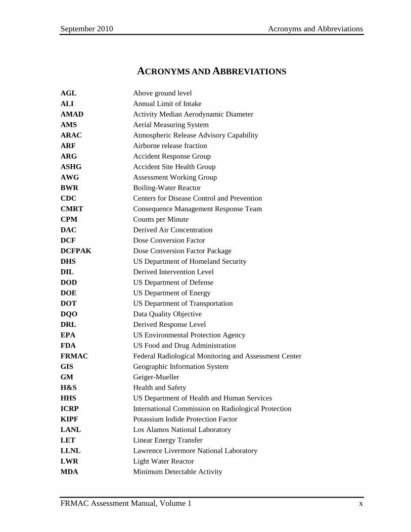
ACRONYMS AND ABBREVIATIONS
AGL Above ground level ALI Annual Limit of Intake AMAD Activity Median Aerodynamic Diameter AMS Aerial Measuring System ARAC Atmospheric Release Advisory Capability ARF Airborne release fraction ARG Accident Response Group ASHG Accident Site Health Group AWG Assessment Working Group BWR Boiling-Water Reactor CDC Centers for Disease Control and Prevention CMRT Consequence Management Response Team CPM Counts per Minute DAC Derived Air Concentration DCF Dose Conversion Factor DCFPAK Dose Conversion Factor Package DHS US Department of Homeland Security DIL Derived Intervention Level DOD US Department of Defense DOE US Department of Energy DOT US Department of Transportation DQO Data Quality Objective DRL Derived Response Level EPA US Environmental Protection Agency FDA US Food and Drug Administration FRMAC Federal Radiological Monitoring and Assessment Center GIS Geographic Information System GM Geiger-Mueller H&S Health and Safety HHS US Department of Health and Human Services ICRP International Commission on Radiological Protection KIPF Potassium Iodide Protection Factor LANL Los Alamos National Laboratory LET Linear Energy Transfer LLNL Lawrence Livermore National Laboratory LWR Light Water Reactor MDA Minimum Detectable Activity
September 2010 Acronyms and Abbreviations
FRMAC Assessment Manual, Volume 1 xi
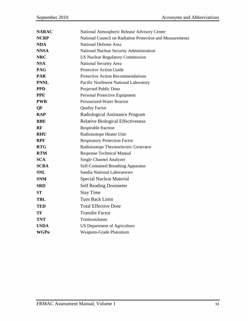
NARAC National Atmospheric Release Advisory Center NCRP National Council on Radiation Protection and Measurements NDA National Defense Area NNSA National Nuclear Security Administration NRC US Nuclear Regulatory Commission NSA National Security Area PAG Protective Action Guide PAR Protective Action Recommendations PNNL Pacific Northwest National Laboratory PPD Projected Public Dose PPE Personal Protective Equipment PWR Pressurized-Water Reactor QF Quality Factor RAP Radiological Assistance Program RBE Relative Biological Effectiveness RF Respirable fraction RHU Radioisotope Heater Unit RPF Respiratory Protection Factor RTG Radioisotope Thermoelectric Generator RTM Response Technical Manual SCA Single Channel Analyzer SCBA Self-Contained Breathing Apparatus SNL Sandia National Laboratories SNM Special Nuclear Material SRD Self Reading Dosimeter ST Stay Time TBL Turn Back Limit TED Total Effective Dose TF Transfer Factor TNT Trinitrotoluene USDA US Department of Agriculture WGPu Weapons-Grade Plutonium
September 2010 Acronyms and Abbreviations
FRMAC Assessment Manual, Volume 1 xii
This page intentionally left blank.
September 2010 Overview
FRMAC Assessment Manual, Volume 1 1
OVERVIEW
Effective Date
Overview ...............................................................................................................1 Introduction .....................................................................................................3 Overview of Assessment .................................................................................5
Assessment Objectives..............................................................................5 Manual Objectives ....................................................................................6
Utilization .......................................................................................................7 Using this Manual .....................................................................................7 Using Data Products .................................................................................7 Differences between FRMAC approach and other published guidance ....................................................................................................8
9/2010

September 2010 Overview
FRMAC Assessment Manual, Volume 1 2
This page intentionally left blank.
September 2010 Overview
FRMAC Assessment Manual, Volume 1 3
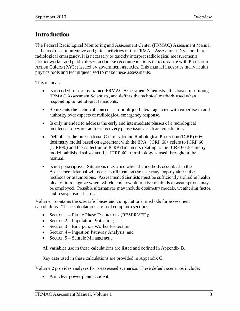
Introduction The Federal Radiological Monitoring and Assessment Center (FRMAC) Assessment Manual is the tool used to organize and guide activities of the FRMAC Assessment Division. In a radiological emergency, it is necessary to quickly interpret radiological measurements, predict worker and public doses, and make recommendations in accordance with Protection Action Guides (PAGs) issued by government agencies. This manual integrates many health physics tools and techniques used to make these assessments.
This manual:
• Is intended for use by trained FRMAC Assessment Scientists. It is basis for training FRMAC Assessment Scientists, and defines the technical methods used when responding to radiological incidents.
• Represents the technical consensus of multiple federal agencies with expertise in and authority over aspects of radiological emergency response.
• Is only intended to address the early and intermediate phases of a radiological incident. It does not address recovery phase issues such as remediation.
• Defaults to the International Commission on Radiological Protection (ICRP) 60+ dosimetry model based on agreement with the EPA. ICRP 60+ refers to ICRP 60 (ICRP90) and the collection of ICRP documents relating to the ICRP 60 dosimetry model published subsequently. ICRP 60+ terminology is used throughout the manual.
• Is not prescriptive. Situations may arise when the methods described in the Assessment Manual will not be sufficient, so the user may employ alternative methods or assumptions. Assessment Scientists must be sufficiently skilled in health physics to recognize when, which, and how alternative methods or assumptions may be employed. Possible alternatives may include dosimetry models, weathering factor, and resuspension factor.
Volume 1 contains the scientific bases and computational methods for assessment calculations. These calculations are broken up into sections:
• Section 1 – Plume Phase Evaluations (RESERVED); • Section 2 – Population Protection; • Section 3 – Emergency Worker Protection; • Section 4 – Ingestion Pathway Analysis; and • Section 5 – Sample Management.
All variables use in these calculations are listed and defined in Appendix B.
Key data used in these calculations are provided in Appendix C.
Volume 2 provides analyses for preassessed scenarios. These default scenarios include:
• A nuclear power plant accident,
September 2010 Overview
FRMAC Assessment Manual, Volume 1 4
• A nuclear weapon accident, • An aged fission product accident, • A nuclear fuel accident, • A radionuclide thermoelectric generator (RTG) accident, • A domestic nuclear explosion (RESERVED), and • A radiological dispersal device (RDD, a.k.a. “dirty bomb”).
Volume 3 addresses FRMAC administrative information and processes relevant to assessment activities.
September 2010 Overview
FRMAC Assessment Manual, Volume 1 5
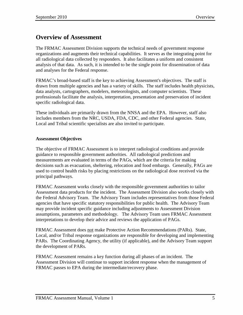
Overview of Assessment The FRMAC Assessment Division supports the technical needs of government response organizations and augments their technical capabilities. It serves as the integrating point for all radiological data collected by responders. It also facilitates a uniform and consistent analysis of that data. As such, it is intended to be the single point for dissemination of data and analyses for the Federal response.
FRMAC’s broad-based staff is the key to achieving Assessment's objectives. The staff is drawn from multiple agencies and has a variety of skills. The staff includes health physicists, data analysts, cartographers, modelers, meteorologists, and computer scientists. These professionals facilitate the analysis, interpretation, presentation and preservation of incident specific radiological data.
These individuals are primarily drawn from the NNSA and the EPA. However, staff also includes members from the NRC, USDA, FDA, CDC, and other Federal agencies. State, Local and Tribal scientific specialists are also invited to participate.
Assessment Objectives
The objective of FRMAC Assessment is to interpret radiological conditions and provide guidance to responsible government authorities. All radiological predictions and measurements are evaluated in terms of the PAGs, which are the criteria for making decisions such as evacuation, sheltering, relocation and food embargo. Generally, PAGs are used to control health risks by placing restrictions on the radiological dose received via the principal pathways.
FRMAC Assessment works closely with the responsible government authorities to tailor Assessment data products for the incident. The Assessment Division also works closely with the Federal Advisory Team. The Advisory Team includes representatives from those Federal agencies that have specific statutory responsibilities for public health. The Advisory Team may provide incident specific guidance including adjustments to Assessment Division assumptions, parameters and methodology. The Advisory Team uses FRMAC Assessment interpretations to develop their advice and reviews the application of PAGs.
FRMAC Assessment does not make Protective Action Recommendations (PARs). State, Local, and/or Tribal response organizations are responsible for developing and implementing PARs. The Coordinating Agency, the utility (if applicable), and the Advisory Team support the development of PARs.
FRMAC Assessment remains a key function during all phases of an incident. The Assessment Division will continue to support incident response when the management of FRMAC passes to EPA during the intermediate/recovery phase.
September 2010 Overview
FRMAC Assessment Manual, Volume 1 6
Manual Objectives
The objectives of the FRMAC Assessment Manual are:
• Provide technical basis for assessments
The manual describes each assessment method in detail, provides references to scientific publications and guidance documents, and specifies the assumptions used.
• Provide technical basis for the Turbo FRMAC Software Package
The Turbo FRMAC Software Package, which was developed under the NA-42 Technology Integration Program, automates the calculations in the assessment manual allowing for rapid computation of important dose assessment data. Turbo FRMAC allows the assessment scientist to vary inputs and change default values to accommodate incident-specific conditions.
• Document the assessment process
The manual defines the Assessment Division’s operations and provides descriptions of organization, functions, and objectives.
• Orientation and Training guide for Assessment Division members
The manual is used to train health physicists to use FRMAC Assessment Methods to evaluate environmental radiological conditions. It also describes the conduct of operations employed by FRMAC.
• Federal family consensus
The manual is based on the guidance issued by the NRC, EPA and FDA and on consensus standards, such as the ICRP and NCRP. It was developed by the FRMAC AWG, and has had broad review from multiple Federal agencies (NNSA, NRC, EPA, FDA, USDA, and CDC) and other participants.
September 2010 Overview
FRMAC Assessment Manual, Volume 1 7
Utilization
Using this Manual
This manual defines the FRMAC process for performing radiological assessment calculations for:
• the Early Phase, • the Intermediate Phase, • the ingestion pathway, and • emergency worker protection.
This manual does not address the Recovery Phase of an incident.
Default Time Phases, PARs and PAGs are defined in the EPA’s Manual of Protective Action Guides and Protective Actions for Nuclear Incidents (EPA PAG Manual) (EPA92).
Volume 1, “Overview and Methods,” provides an overview of Assessment and detailed descriptions of generalized assessment methods. These methods are NOT prescriptive. If a method is inappropriate for the incident, the Assessment Scientists should use their best judgment and implement a more appropriate method. Volume 1 also includes supporting information (e.g., default values for variables used in the methods) for performing the methods under certain conditions and assumptions.
Volume 2, “Pre-assessed Default Scenarios,” provides default assessment guidance for different types of accidents. A section is devoted to each generic scenario, that describes default Derived Response Levels (DRLs) and Derived Intervention Levels (DILs) and methodologies. Default accident scenario cases are not necessarily worst possible cases, but are those more likely to exist.
Volume 3, “Assessment Operations Overview and Procedures,” offers guidance and procedures for internal FRMAC Assessment conduct of operations.
Using Data Products
Assessment prepares a variety of data products, each designed for a particular audience and application. The products may be interpretations, analyses, and assessed data sets or reference information. Most data products are presented as maps. PAG Zone Maps and Monitoring/Sampling Status Maps are the primary data products generated for release and communication to local decision makers. FRMAC emphasizes production, approval, and release of these products to summarize Assessment’s appraisal of the radiological incident.
• The PAG Zone Maps indicate where particular PAGs might be exceeded. Initially, the PAG Zone Maps are based only on modeling predictions. The maps are updated as monitoring and sampling measurements become available.
September 2010 Overview
FRMAC Assessment Manual, Volume 1 8
• The Monitoring/Sampling Status Maps summarize the location and type of both monitoring and sampling data collected up to the current time. The purpose of these maps is to portray the progress of the monitoring effort and to indicate the confidence level of the PAG Zone Map.
The following data products are intended for internal Assessment use by health physics professionals performing independent interpretations or analyses. These data products may be made available outside the FRMAC; however they are not produced on a regular schedule.
• Predictive Model Maps – exposure/dose rate, areal deposition or integrated exposure/dose
• Monitoring/Sampling Maps - measurements of exposure/dose rate, areal deposition or integrated exposure/dose estimations
• Assessed Data - field measurements and/or sample analysis results
• Calculation Analyses - DRLs/DILs, estimated doses, radionuclide mix, resuspension factor, etc.
Other data products may be developed to meet specific needs as the event progresses. All of the above data products, and others, are created as drafts or preliminary results during the Assessment process and usually precede approved products by a significant period of time. These are not available for release outside of the FRMAC because their quality cannot be assured. Representatives of other FRMAC Divisions, Federal Agencies, the Advisory Team or local governmental authorities may have access to the draft or preliminary products within the FRMAC. This information may be used to relay progress of monitoring and sampling or developing trends to counterparts.
Data products that have not been approved by the FRMAC Director should NEVER be released and MUST NOT be used for determining PARs.
Differences between FRMAC approach and other published guidance
The FRMAC Assessment Working Group (AWG) approves the methods used in this manual. The AWG includes knowledgeable subject matter experts from diverse government entities. The goal of the AWG is to craft a set of methods that represent a unified federal consensus and are implemented by member agencies.
The FRMAC intends that this manual will be responsive to new technical developments. The AWG reviews technical developments as they become available and evaluates them for inclusion in this manual. Therefore, this manual may vary from individual guidance documents as new developments are incorporated.
The FRMAC Assessment Division implements the best health physics practices to perform radiological assessments. These practices may differ from those in other agencies’ publications due to a difference in publication date or based upon alternate assumptions.
September 2010 Section 1 – Plume Assessment Methods
FRMAC Assessment Manual, Volume 1 1.0-1
SECTION 1. PLUME ASSESSMENT METHODS
Effective
Date
Introduction ........................................................................................ 1.0-3 Reserved
Method 1.1 Plume Air Activity Derived Response Level (Pl_DRLair) ..................................................................... 1.1-1 Reserved
Method 1.2 Plume Deposition Derived Response Level (Pl_DRLground) ................................................................ 1.2-1 Reserved
Method 1.3 Plume Dose and Exposure Rate Derived Response Level (Pl_DRLDR and Pl_DRLXR) ................................. 1.3-1 Reserved
Method 1.4 Plume Alpha Derived Response Level (Pl_DRLα) ......... 1.4-1 Reserved
Method 1.5 Plume Beta Derived Response Level (Pl_DRLβ) ........... 1.5-1 Reserved
Method 1.6 Plume Phase Projected Public Dose (Pl_PPD) ............... 1.6-1 Reserved
Method 1.7 Plume Phase Public Skin Dose ....................................... 1.7-1 Reserved
THIS SECTION IS RESERVED FOR FUTURE DEVELOPMENT.

September 2010 Section 1 – Plume Assessment Methods
FRMAC Assessment Manual, Volume 1 1.0-2
This page intentionally left blank.
September 2010 Section 2 – Deposition Assessment Methods
FRMAC Assessment Manual, Volume 1 2.0-1
SECTION 2. DEPOSITION ASSESSMENT METHODS
Effective Date
Introduction ........................................................................................ 2.0-3 9/2010
Method 2.1 Deposition Derived Response Level (Dp_DRL) ............ 2.1-1 9/2010
Method 2.2 Deposition Dose and Exposure Rate Derived Response Level (Dp_DRLDR and Dp_DRLXR) .............. 2.2-1 9/2010
Method 2.3 Deposition Alpha Derived Response Level (Dp_DRLα) ..................................................................... 2.3-1 9/2010
Method 2.4 Deposition Beta Derived Response Level (Dp_DRLβ) ..................................................................... 2.4-1 9/2010
Method 2.5 Deposition Projected Public Dose (Dp_PPD) ................ 2.5-1 9/2010
Method 2.6 Deposition Public Skin Dose .......................................... 2.6-1 Reserved
Method 2.7 Determining Return Times ............................................. 2.7-1 Reserved
Method 2.8 Assessing Nuclear Detonations ...................................... 2.8-1 9/2010

September 2010 Section 2 – Deposition Assessment Methods
FRMAC Assessment Manual, Volume 1 2.0-2
This page intentionally left blank.
September 2010 Section 2 – Deposition Assessment Methods
FRMAC Assessment Manual, Volume 1 2.0-3
Introduction to Deposition Assessment Methods The methods in this section assist Assessment Scientists in evaluating potential hazards to members of the public from a radiological incident. Methods include developing DRLs and projecting doses by relating values from modeling projections or field monitoring results to established PAGs. (See Appendix C, Table 2-2 for PAG values.)
Methods in this section have been developed to address hazards from exposure to a ground deposition of radioactive material.
Assumptions
FRMAC radiological assessment calculations utilize the default assumptions established by the FRMAC AWG.
The following default assumptions are used in the methods in this section:
1) The dose projections from this section include contributions from external exposure (groundshine) and the inhalation of resuspended material.
2) Inhalation of material from the passage of a plume of radioactive material is not considered in these calculations. The plume is considered to have already passed. Dose consequences from direct inhalation, submersion, and cloud shine are not included in the calculations. (See Section 1 of this Volume for Plume Phase calculations.)
3) The effects of radioactive decay, weathering and resuspension are included in the calculations.
4) Ingestion is not included in these methods. If ingestion is a significant dose pathway (i.e., >10% of the total dose), it should be addressed separately and included in protective action decisions. (See Ingestion Methods, Section 4.)
5) Default calculations assume:
a. the receptor is outside in the contaminated area continuously during the time phase under consideration without any protective measures (e.g., shielding, respiratory protection);
b. chronic exposure; calculations addressing acute exposures are planned for future methods.
c. use of ICRP 60+ dosimetry model; d. adult receptor; e. an Activity Averaged Breathing Rate of 0.92 m3/hr; and f. inhalation of 1-micron Activity Median Aerodynamic Diameter (AMAD)
particles in the Maximum lung clearance class.
6) Parent – Daughter inclusion rules:
• Daughter radionuclides are included in calculations if:
September 2010 Section 2 – Deposition Assessment Methods
FRMAC Assessment Manual, Volume 1 2.0-4
a. Daughter’s half-life is less than the half-life of the ultimate parent (i.e., first parent in decay series), and
b. Daughter’s half-life is less than 1.5 yr. • Daughter radionuclides that meet these rules are considered to be in equilibrium
(secular, or transient when branching ratio ≠ 1) at deposition (t = 0, i.e., the daughter radionuclides are not grown in to equilibrium activities), and are assigned the parent’s half life and decay constants for calculations.
• Daughter radionuclides that do not meet these rules are excluded from the calculations (as are all subsequent daughter radionuclides, regardless of half life).
• Optionally, an alternate calculation that models the decay and in-growth of the entire radionuclide decay chain may be used when the using the default Parent – Daughter inclusion rules stated above is not desired. See Appendix F, Supplement 1 for details on the calculation.
7) FRMAC’s public protection methods generally assume that the organ of interest is the whole body. However, other organs may be evaluated against applicable Protective Action Guides (PAGs) by changing the Dose Coefficients and PAGs used. (See Method 2.1 Example 1, Section E1.6.)
Inputs The following information is required for the methods described in this section:
• Data – This information may come from predictive analysis (models) or field data (monitoring and/or samples):
o Composition of the deposited radionuclide mixture (radionuclides and areal radioactivity, concentration, activity ratio or mass ratio) and/or external dose (or exposure) rates.
• Other Factors: o Ground roughness; o Weathering; o Resuspension; and o Decay of radionuclides during the time period under consideration.
• Constants: o Breathing rate; o Inhalation dose coefficient; o External dose coefficient; o Dose limits (e.g., PAGs); and o Exposure to Dose conversion factor (default of 1.0 mrem/mR).
• Time Phase: o Evaluation Time (tn) – The point in time, relative to the start of the event, for
which the calculation is being performed; and o The start (t1) and end (t2) time of period under consideration. The EPA and DHS
have established certain time phases (early, intermediate, etc.) with specified
September 2010 Section 2 – Deposition Assessment Methods
FRMAC Assessment Manual, Volume 1 2.0-5
durations, but the time phase may be set to any period chosen by local authorities for a specific event. The start of the time phase may be set to a time other than the time of the initial event to not include the unavoidable dose received before protective actions may be initiated.
The calculations presented in these methods are applicable to all EPA-defined as well as any user-defined time phases. To accommodate calculations for varying time phases, adjust the beginning (t1) and ending (t2) of the integration period to the desired values. For example, to calculate a value for the second year, set t1 and t2 to 366 and 730 days, respectively.
NOTE: Many of the terms in the methods are dependent on variables (e.g., time phase, target organ, PAG, etc.). When critical, these dependencies are shown as subscripts to the appropriate terms. (See Appendix B for the variable list.)

September 2010 Section 2 – Deposition Assessment Methods
FRMAC Assessment Manual, Volume 1 2.0-6
This page intentionally left blank.
September 2010 Method 2.1 – Deposition DRL
FRMAC Assessment Manual, Volume 1 2.1-1
METHOD 2.1 DEPOSITION DERIVED RESPONSE LEVEL
Application This method has been developed to calculate a Deposition Derived Response Level (Dp_DRL) for a deposition of radioactive material.
The Dp_DRL:
• Represents the ground concentration, or areal activity (µCi/m2), at a given time (tn) of a marker radionuclide in a mixture of radionuclides that will be expected to cause the entire mixture to produce a dose equal to the appropriate Protective Action Guide (PAG) over the time phase under consideration.
• Is derived from the PAGs for radiological emergency planning established by the Environmental Protection Agency (EPA) (EPA92) or the Department of Homeland Security (DHS) (DHS08). A projected or measured deposition value greater than the Dp_DRL indicates that the PAG has the potential to be exceeded.
• Is used to create data products and define contamination levels for a marker radionuclide to assist decision makers in determining where it may be advisable to implement protective actions (e.g., sheltering, evacuation, relocation).
Discussion The Dp_DRL combines a Total Dose Parameter for Deposition (TDP_Dp), made up of internal and external dose parameters, with the deposition (areal activity) values for each radionuclide present in a mixture and relates that product (MTDP_Dp) to the PAG for the time phase under consideration and the areal activity of the marker radionuclide.
The Dp_DRL is based on the ratio of activities of each radionuclide in a mixture, not the individual activity values of those radionuclides.
The marker radionuclide, chosen for ease of detection with available instrumentation, is used to eliminate the need to separately measure the concentration of every radionuclide in the environmental medium, once a relative ratio of the amount of each radionuclide present is known.
NOTE: The Dp_DRL may be calculated for Stochastic (Chronic) or Deterministic (Acute) doses. At this time, only Stochastic doses are calculated by this method; information for calculating Deterministic doses will be included at a future date.
September 2010 Method 2.1 – Deposition DRL
FRMAC Assessment Manual, Volume 1 2.1-2
Assumptions There are no additional assumptions beyond the default assumptions.
Inputs There are no additional inputs beyond the default inputs.
If incident-specific values have not been established, recommended default values for selected inputs are available in Appendix C.
Outputs The final output of this method is the Dp_DRL value for a marker radionuclide from a deposition of radioactive material.
Final
Dp_DRL = Deposition Derived Response Level, the areal activity, at time tn, of the marker radionuclide at which the dose from all radionuclides in a deposition mixture would result in a dose equal to the PAG for the time phase under consideration, µCi/m2
Intermediate
The following intermediate values may be referenced in other methods and are called out here for clarity.
MTDP_Dp = Mixture Total Dose Parameter for Deposition for all radionuclides in the mixture of interest (mrem)
TDP_Dp = Total Dose Parameter for Deposition for each radionuclide (mrem•m2/µCi)
InhDP_Dp = Inhalation Dose Parameter for Deposition (mrem•m2/µCi) ExDP_Dp = External Dose Parameter for Deposition (mrem•m2/µCi)
Calculation Calculating the Dp_DRL can be challenging, especially when considering complex radionuclide mixtures or a single radionuclide with multiple progeny in equilibrium. Therefore the user is urged to use a computer code, such as Turbo FRMAC, to complete these calculations.
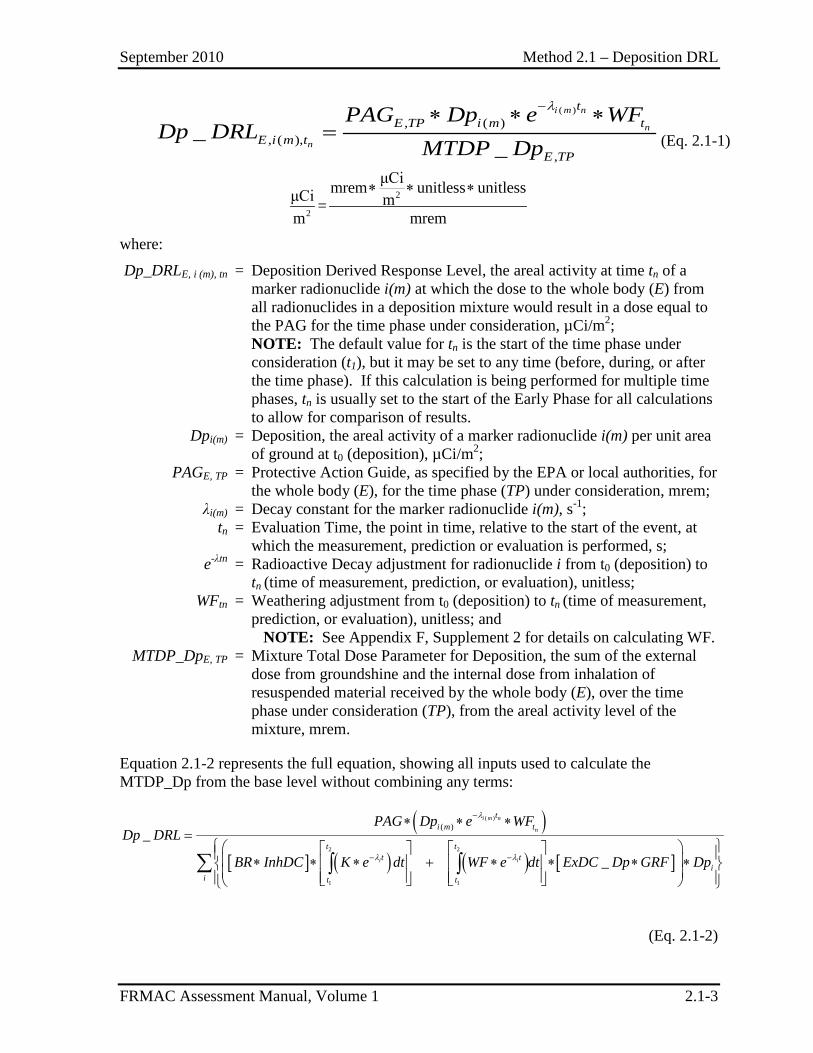
Equation 2.1-1 represents the final form of the Dp_DRL calculation:
September 2010 Method 2.1 – Deposition DRL
FRMAC Assessment Manual, Volume 1 2.1-3
( ), ( )
, ( ),,
__
i m n
n
n
tE TP i m t
E i m tE TP
PAG Dp e WFDp DRL
MTDP Dp
λ−∗ ∗ ∗= (Eq. 2.1-1)
2
2
μCimrem unitless unitlessμCi m=m mrem
∗ ∗ ∗
where:
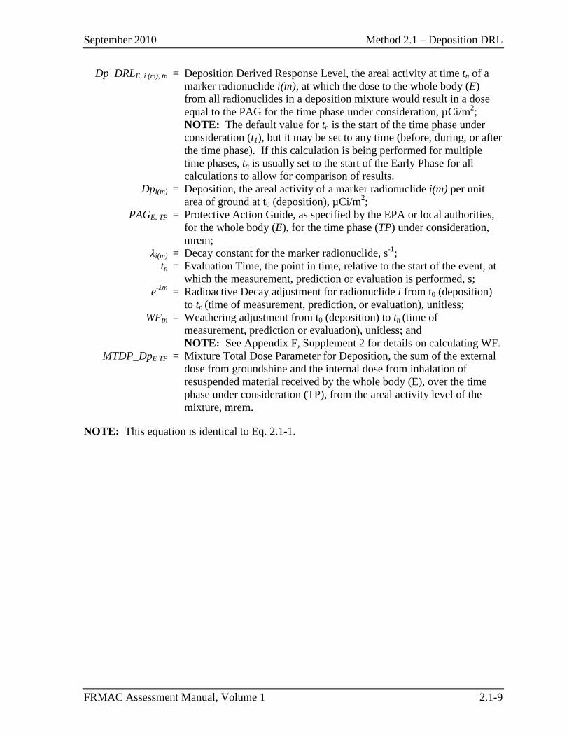
Dp_DRLE, i (m), tn = Deposition Derived Response Level, the areal activity at time tn of a marker radionuclide i(m) at which the dose to the whole body (E) from all radionuclides in a deposition mixture would result in a dose equal to the PAG for the time phase under consideration, µCi/m2;
NOTE: The default value for tn is the start of the time phase under consideration (t1), but it may be set to any time (before, during, or after the time phase). If this calculation is being performed for multiple time phases, tn is usually set to the start of the Early Phase for all calculations to allow for comparison of results.
Dpi(m) = Deposition, the areal activity of a marker radionuclide i(m) per unit area of ground at t0 (deposition), µCi/m2;
PAGE, TP = Protective Action Guide, as specified by the EPA or local authorities, for the whole body (E), for the time phase (TP) under consideration, mrem;
λi(m) = Decay constant for the marker radionuclide i(m), s-1; tn = Evaluation Time, the point in time, relative to the start of the event, at
which the measurement, prediction or evaluation is performed, s; e-λtn = Radioactive Decay adjustment for radionuclide i from t0 (deposition) to
tn (time of measurement, prediction, or evaluation), unitless; WFtn = Weathering adjustment from t0 (deposition) to tn (time of measurement,
prediction, or evaluation), unitless; and NOTE: See Appendix F, Supplement 2 for details on calculating WF. MTDP_DpE, TP = Mixture Total Dose Parameter for Deposition, the sum of the external
dose from groundshine and the internal dose from inhalation of resuspended material received by the whole body (E), over the time phase under consideration (TP), from the areal activity level of the mixture, mrem.
Equation 2.1-2 represents the full equation, showing all inputs used to calculate the MTDP_Dp from the base level without combining any terms:
( )[ ] ( ) ( ) [ ]
( )
2 2
1 1
( )_
_
λ
λ λ
−
− −
∗ ∗ ∗=
∗ ∗ ∗ + ∗ ∗ ∗ ∗ ∑ ∫ ∫
i m n
n
i i
ti m t
t tt t
ii t t
PAG Dp e WFDp DRL
BR InhDC K e dt WF e dt ExDC Dp GRF Dp
(Eq. 2.1-2)
September 2010 Method 2.1 – Deposition DRL
FRMAC Assessment Manual, Volume 1 2.1-4
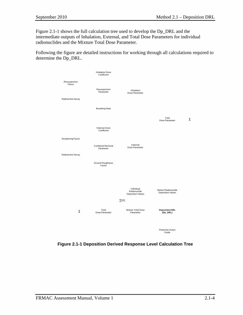
Figure 2.1-1 shows the full calculation tree used to develop the Dp_DRL and the intermediate outputs of Inhalation, External, and Total Dose Parameters for individual radionuclides and the Mixture Total Dose Parameter.
Following the figure are detailed instructions for working through all calculations required to determine the Dp_DRL.
Inhalation Dose Coefficient
Breathing Rate
TotalDose Parameter
External Dose Coefficient
Ground Roughness Factor
InhalationDose Parameter
ExternalDose Parameter
TotalDose Parameter
Individual Radionuclide
Deposition Values
Deposition DRL(Dp_DRL)
Marker Radionuclide Deposition Values
Mixture Total Dose Parameter
Resuspension Factor
Radioactive Decay
Resuspension Parameter
Weathering Factor
Radioactive Decay
Combined Removal Parameter
Protective Action Guide
1
1
∑(X)
Figure 2.1-1 Deposition Derived Response Level Calculation Tree
September 2010 Method 2.1 – Deposition DRL
FRMAC Assessment Manual, Volume 1 2.1-5
1.0 Calculating the Deposition Derived Response Level The Dp_DRL is a value that is used to relate an areal activity (e.g., μCi/m2) of a specific (marker) radionuclide (Dpi(m)) present in a mixture to the hazard posed by the entire mixture over the time phase under consideration relative to the regulatory PAG.
A prime factor in determining the Dp_DRL is the Total Dose Parameter (TDP_Dp) for each radionuclide present in the mixture. The TDP_Dp is obtained by adding an Inhalation Dose Parameter (InhDP_Dp) and an External Dose Parameter (ExDP_Dp).
NOTE: If inhalation of resuspended radioactive material is not a concern, then the InhDP_Dp is essentially zero and the TDP_Dp is equal to the ExDP_Dp and Section 1.1 may be skipped.
The TDP_Dp for each radionuclide is then multiplied by the areal activity of that radionuclide present in the mixture (Dpi) and those products are then summed over all of the radionuclides in the mixture. The resulting value, called the Mixture Total Dose Parameter for Deposition (MTDP_Dp), can then be related to the PAG and the areal activity of the chosen marker radionuclide, as shown in Equation 2.1-1, to determine the Dp_DRL.
The following sections provide step-by-step instructions for the manual calculation of a Dp_DRL, beginning with determining the TDP_Dp for each radionuclide, then finding a MTDP_Dp for the mixture, and finally calculating the Dp_DRL for the chosen marker radionuclide present in the mixture.
1.1 Calculation of the Internal Dose Component of the Total Dose Parameter
Inhalation Dose Parameter
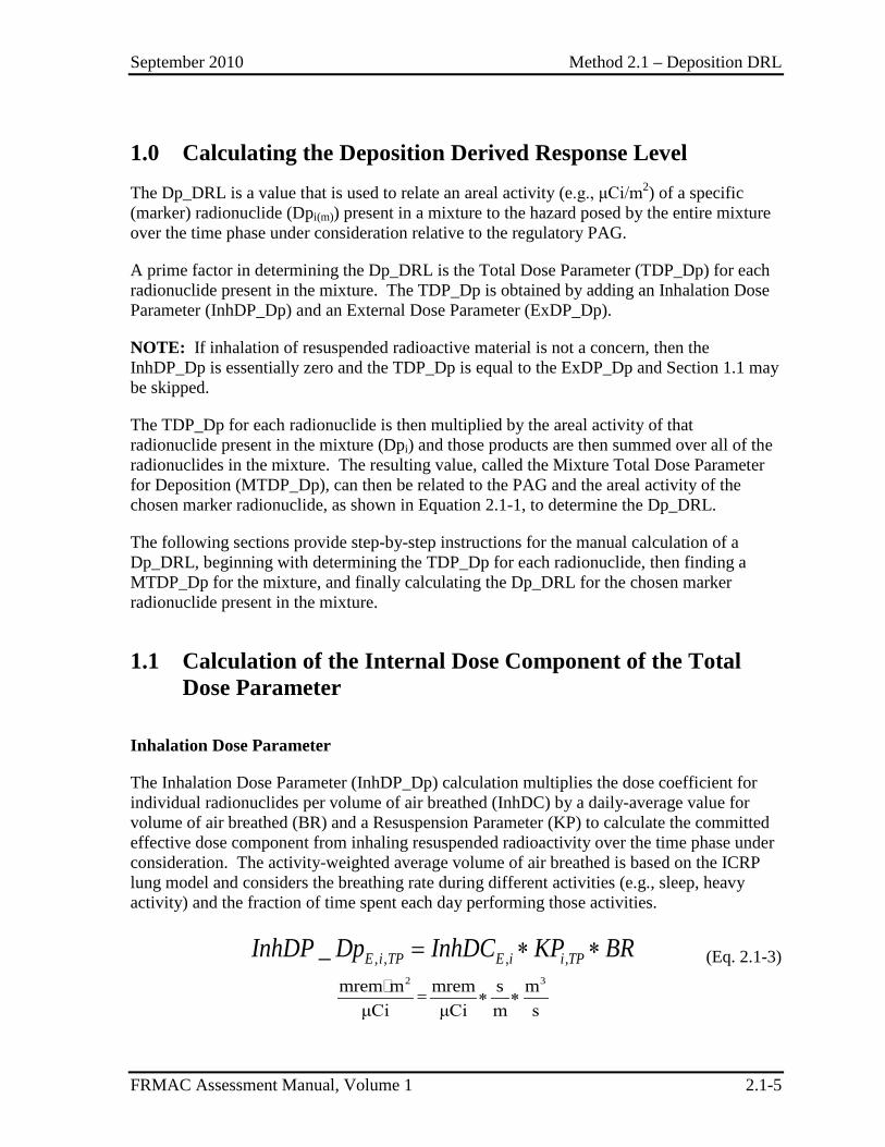
The Inhalation Dose Parameter (InhDP_Dp) calculation multiplies the dose coefficient for individual radionuclides per volume of air breathed (InhDC) by a daily-average value for volume of air breathed (BR) and a Resuspension Parameter (KP) to calculate the committed effective dose component from inhaling resuspended radioactivity over the time phase under consideration. The activity-weighted average volume of air breathed is based on the ICRP lung model and considers the breathing rate during different activities (e.g., sleep, heavy activity) and the fraction of time spent each day performing those activities.
, , , ,_ = ∗ ∗E i TP E i i TPInhDP Dp InhDC KP BR (Eq. 2.1-3)
2 3mrem m mrem s m=
μCi μCi m s∗ ∗
September 2010 Method 2.1 – Deposition DRL
FRMAC Assessment Manual, Volume 1 2.1-6
where:
InhDP_DpE, i, TP = Inhalation Dose Parameter for Deposition, the committed effective dose received by the whole body (E), from the inhalation of resuspended radionuclide i over the time phase under consideration (TP), per unit of areal activity of the radionuclide deposited on the ground, mrem•m2/µCi;
InhDCE ,i = Inhalation Dose Coefficient, the committed effective dose coefficient for the whole body (E), for radionuclide i (values from ICRP 60+ dosimetry models, DCFPAK), mrem/ µCi;
KPi, TP = Resuspension Parameter, value that adjusts the airborne radioactivity level of radionuclide i over the time phase (TP) under consideration for radioactive decay and the time-dependent resuspension factor (K) (value obtained numerically from Turbo FRMAC), s/m; and
NOTE: See Appendix F, Supplement 2 for details on calculating KP.
BR = Breathing Rate, the activity-weighted average volume of air breathed per unit time by an adult male (ICRP, 1994, Table B.16B), 2.56E-04 m3/s.
1.2 Calculation of the External Dose Component of the Total Dose Parameter
External Dose Parameter
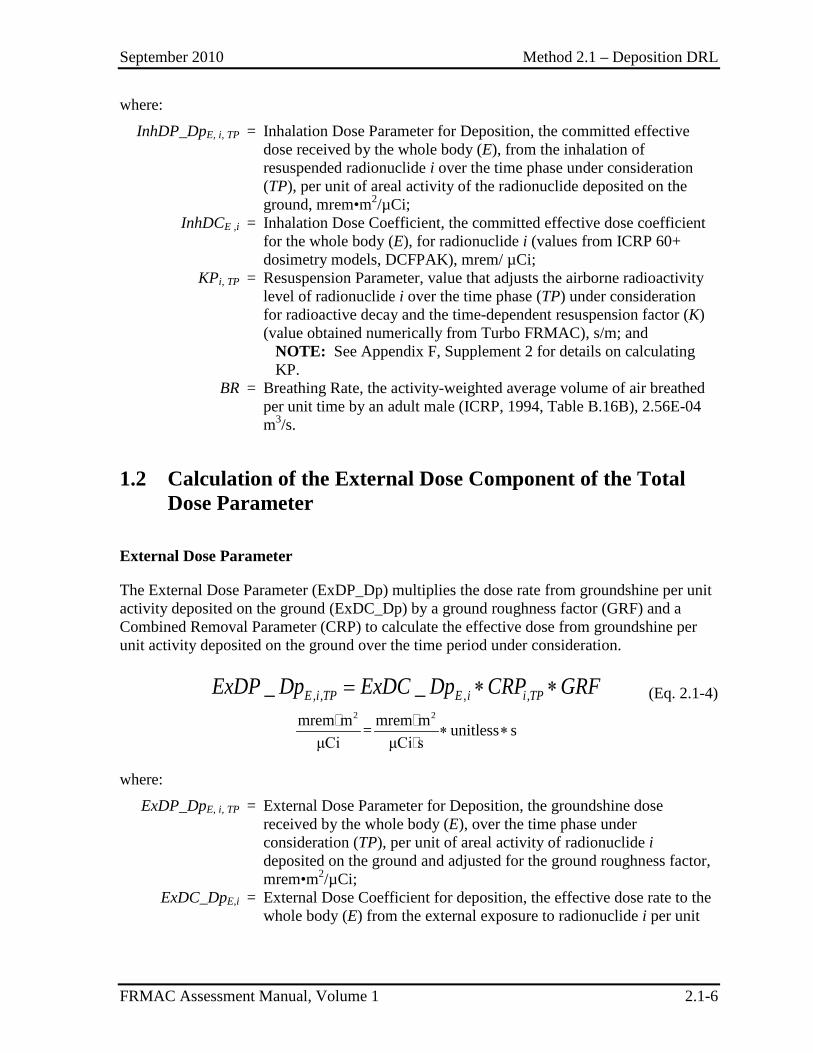
The External Dose Parameter (ExDP_Dp) multiplies the dose rate from groundshine per unit activity deposited on the ground (ExDC_Dp) by a ground roughness factor (GRF) and a Combined Removal Parameter (CRP) to calculate the effective dose from groundshine per unit activity deposited on the ground over the time period under consideration.
, , , ,_ _= ∗ ∗E i TP E i i TPExDP Dp ExDC Dp CRP GRF (Eq. 2.1-4)
2 2mrem m mrem m= unitless s
μCi μCi s∗ ∗
where:
ExDP_DpE, i, TP = External Dose Parameter for Deposition, the groundshine dose received by the whole body (E), over the time phase under consideration (TP), per unit of areal activity of radionuclide i deposited on the ground and adjusted for the ground roughness factor, mrem•m2/µCi;
ExDC_DpE,i = External Dose Coefficient for deposition, the effective dose rate to the whole body (E) from the external exposure to radionuclide i per unit
September 2010 Method 2.1 – Deposition DRL
FRMAC Assessment Manual, Volume 1 2.1-7
activity deposited on the ground(values from DCFPAK using ICRP 60+ dosimetry models), mrem•m2/ µCi•s;
CRPi, TP = Combined Removal Parameter, value that adjusts for radioactive decay and weathering effects that decrease the amount of radionuclide i available to cause direct exposure or to be ingested over the time phase (TP) under consideration, s; and
NOTE: See Appendix F, Supplement 2 for details on calculating CRP.
GRF = Ground Roughness Factor, a constant (0.82) that compensates for the fact that the external exposure is not coming from an infinite flat plane (An02), unitless.
1.3 Combining Internal and External Components of the Total Dose Parameter
Total Dose Parameter
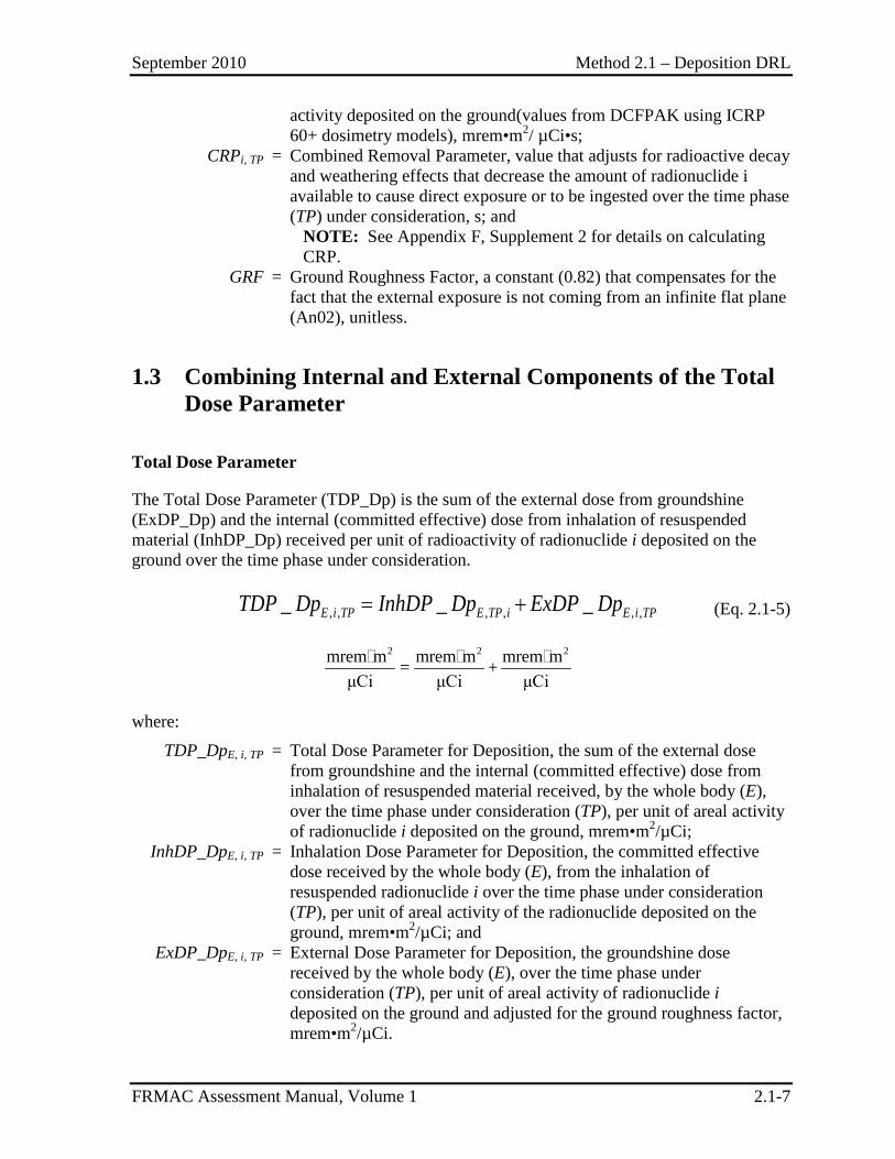
The Total Dose Parameter (TDP_Dp) is the sum of the external dose from groundshine (ExDP_Dp) and the internal (committed effective) dose from inhalation of resuspended material (InhDP_Dp) received per unit of radioactivity of radionuclide i deposited on the ground over the time phase under consideration.
, , , , , ,_ _ _E i TP E TP i E i TPTDP Dp InhDP Dp ExDP Dp= + (Eq. 2.1-5)
2 2 2mrem m mrem m mrem m= +
μCi μCi μCi
where:
TDP_DpE, i, TP = Total Dose Parameter for Deposition, the sum of the external dose from groundshine and the internal (committed effective) dose from inhalation of resuspended material received, by the whole body (E), over the time phase under consideration (TP), per unit of areal activity of radionuclide i deposited on the ground, mrem•m2/µCi;
InhDP_DpE, i, TP = Inhalation Dose Parameter for Deposition, the committed effective dose received by the whole body (E), from the inhalation of resuspended radionuclide i over the time phase under consideration (TP), per unit of areal activity of the radionuclide deposited on the ground, mrem•m2/µCi; and
ExDP_DpE, i, TP = External Dose Parameter for Deposition, the groundshine dose received by the whole body (E), over the time phase under consideration (TP), per unit of areal activity of radionuclide i deposited on the ground and adjusted for the ground roughness factor, mrem•m2/µCi.
September 2010 Method 2.1 – Deposition DRL
FRMAC Assessment Manual, Volume 1 2.1-8
1.4 Calculating the Total Dose Parameter for the Mixture NOTE: See the default assumptions for daughter radionuclide inclusion rules.
Mixture Total Dose Parameter for Deposition (MTDP_Dp)
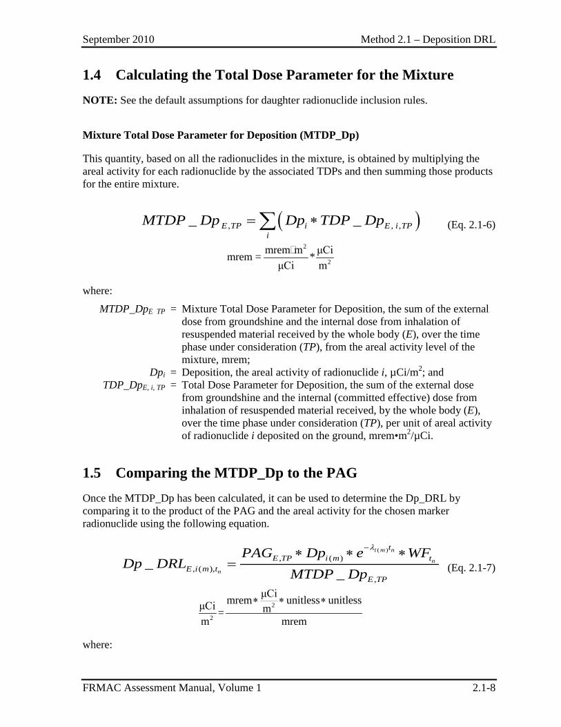
This quantity, based on all the radionuclides in the mixture, is obtained by multiplying the areal activity for each radionuclide by the associated TDPs and then summing those products for the entire mixture.
( ), , ,_ _= ∗∑E TP i E i TPi
MTDP Dp Dp TDP Dp (Eq. 2.1-6)
2
2
mrem m μCimrem = *μCi m
where:
MTDP_DpE TP = Mixture Total Dose Parameter for Deposition, the sum of the external dose from groundshine and the internal dose from inhalation of resuspended material received by the whole body (E), over the time phase under consideration (TP), from the areal activity level of the mixture, mrem;
Dpi = Deposition, the areal activity of radionuclide i, µCi/m2; and TDP_DpE, i, TP = Total Dose Parameter for Deposition, the sum of the external dose
from groundshine and the internal (committed effective) dose from inhalation of resuspended material received, by the whole body (E), over the time phase under consideration (TP), per unit of areal activity of radionuclide i deposited on the ground, mrem•m2/µCi.
1.5 Comparing the MTDP_Dp to the PAG Once the MTDP_Dp has been calculated, it can be used to determine the Dp_DRL by comparing it to the product of the PAG and the areal activity for the chosen marker radionuclide using the following equation.
( ), ( )
, ( ),,
__
i m n
n
n
tE TP i m t
E i m tE TP
PAG Dp e WFDp DRL
MTDP Dp
λ−∗ ∗ ∗= (Eq. 2.1-7)
2
2
μCimrem unitless unitlessμCi m=m mrem
∗ ∗ ∗
where:
September 2010 Method 2.1 – Deposition DRL
FRMAC Assessment Manual, Volume 1 2.1-9
Dp_DRLE, i (m), tn = Deposition Derived Response Level, the areal activity at time tn of a marker radionuclide i(m), at which the dose to the whole body (E) from all radionuclides in a deposition mixture would result in a dose equal to the PAG for the time phase under consideration, µCi/m2;
NOTE: The default value for tn is the start of the time phase under consideration (t1), but it may be set to any time (before, during, or after the time phase). If this calculation is being performed for multiple time phases, tn is usually set to the start of the Early Phase for all calculations to allow for comparison of results.
Dpi(m) = Deposition, the areal activity of a marker radionuclide i(m) per unit area of ground at t0 (deposition), µCi/m2;
PAGE, TP = Protective Action Guide, as specified by the EPA or local authorities, for the whole body (E), for the time phase (TP) under consideration, mrem;
λi(m) = Decay constant for the marker radionuclide, s-1; tn = Evaluation Time, the point in time, relative to the start of the event, at
which the measurement, prediction or evaluation is performed, s; e-λtn = Radioactive Decay adjustment for radionuclide i from t0 (deposition)
to tn (time of measurement, prediction, or evaluation), unitless; WFtn = Weathering adjustment from t0 (deposition) to tn (time of
measurement, prediction or evaluation), unitless; and NOTE: See Appendix F, Supplement 2 for details on calculating WF.
MTDP_DpE TP = Mixture Total Dose Parameter for Deposition, the sum of the external dose from groundshine and the internal dose from inhalation of resuspended material received by the whole body (E), over the time phase under consideration (TP), from the areal activity level of the mixture, mrem.
NOTE: This equation is identical to Eq. 2.1-1.
September 2010 Method 2.1 – Deposition DRL
FRMAC Assessment Manual, Volume 1 2.1-10
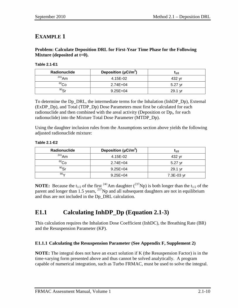
EXAMPLE 1
Problem: Calculate Deposition DRL for First-Year Time Phase for the Following Mixture (deposited at t=0).
Table 2.1-E1
Radionuclide Deposition (μCi/m2) t1/2 241Am 4.15E-02 432 yr 60Co 2.74E+04 5.27 yr 90Sr 9.25E+04 29.1 yr
To determine the Dp_DRL, the intermediate terms for the Inhalation (InhDP_Dp), External (ExDP_Dp), and Total (TDP_Dp) Dose Parameters must first be calculated for each radionuclide and then combined with the areal activity (Deposition or Dpi, for each radionuclide) into the Mixture Total Dose Parameter (MTDP_Dp).
Using the daughter inclusion rules from the Assumptions section above yields the following adjusted radionuclide mixture:
Table 2.1-E2
Radionuclide Deposition (μCi/m2) t1/2 241Am 4.15E-02 432 yr 60Co 2.74E+04 5.27 yr 90Sr 9.25E+04 29.1 yr 90Y 9.25E+04 7.3E-03 yr
NOTE: Because the t1/2 of the first 241Am daughter (237Np) is both longer than the t1/2 of the parent and longer than 1.5 years, 237Np and all subsequent daughters are not in equilibrium and thus are not included in the Dp_DRL calculation.
E1.1 Calculating InhDP_Dp (Equation 2.1-3) This calculation requires the Inhalation Dose Coefficient (InhDC), the Breathing Rate (BR) and the Resuspension Parameter (KP).
E1.1.1 Calculating the Resuspension Parameter (See Appendix F, Supplement 2)
NOTE: The integral does not have an exact solution if K (the Resuspension Factor) is in the time-varying form presented above and thus cannot be solved analytically. A program capable of numerical integration, such as Turbo FRMAC, must be used to solve the integral.
September 2010 Method 2.1 – Deposition DRL
FRMAC Assessment Manual, Volume 1 2.1-11
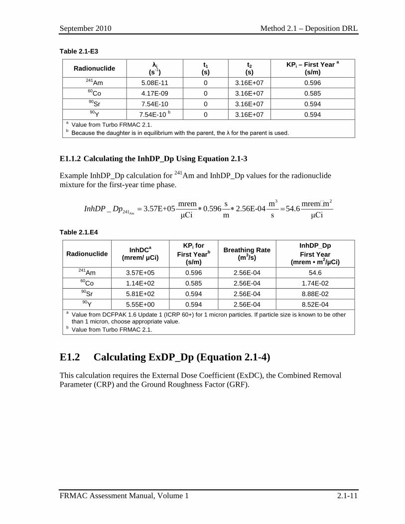
Table 2.1-E3
Radionuclide λi (s-1)
t1 (s)
t2 (s)
KPi – First Year a
(s/m) 241Am 5.08E-11 0 3.16E+07 0.596 60Co 4.17E-09 0 3.16E+07 0.585 90Sr 7.54E-10 0 3.16E+07 0.594 90Y 7.54E-10 b 0 3.16E+07 0.594
a Value from Turbo FRMAC 2.1. b Because the daughter is in equilibrium with the parent, the λ for the parent is used.
E1.1.2 Calculating the InhDP_Dp Using Equation 2.1-3
Example InhDP_Dp calculation for 241Am and InhDP_Dp values for the radionuclide mixture for the first-year time phase.
Am
3 2
241mrem s m mrem m_ 3.57E+05 0.596 2.56E-04 54.6μCi m s μCi
= ∗ ∗ =InhDP Dp
Table 2.1.E4
Radionuclide InhDCa
(mrem/ μCi)
KPi for First Yearb
(s/m)
Breathing Rate (m3/s)
InhDP_Dp First Year
(mrem • m2/µCi) 241Am 3.57E+05 0.596 2.56E-04 54.6 60Co 1.14E+02 0.585 2.56E-04 1.74E-02 90Sr 5.81E+02 0.594 2.56E-04 8.88E-02 90Y 5.55E+00 0.594 2.56E-04 8.52E-04
a Value from DCFPAK 1.6 Update 1 (ICRP 60+) for 1 micron particles. If particle size is known to be other than 1 micron, choose appropriate value.
b Value from Turbo FRMAC 2.1.
E1.2 Calculating ExDP_Dp (Equation 2.1-4) This calculation requires the External Dose Coefficient (ExDC), the Combined Removal Parameter (CRP) and the Ground Roughness Factor (GRF).
September 2010 Method 2.1 – Deposition DRL
FRMAC Assessment Manual, Volume 1 2.1-12
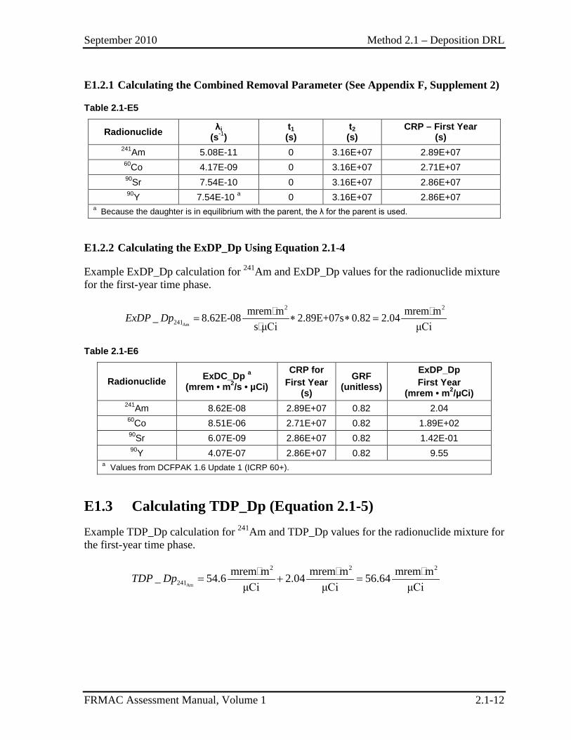
E1.2.1 Calculating the Combined Removal Parameter (See Appendix F, Supplement 2)
Table 2.1-E5
Radionuclide λi (s-1)
t1 (s)
t2 (s)
CRP – First Year
(s) 241Am 5.08E-11 0 3.16E+07 2.89E+07 60Co 4.17E-09 0 3.16E+07 2.71E+07 90Sr 7.54E-10 0 3.16E+07 2.86E+07 90Y 7.54E-10 a 0 3.16E+07 2.86E+07
a Because the daughter is in equilibrium with the parent, the λ for the parent is used.
E1.2.2 Calculating the ExDP_Dp Using Equation 2.1-4
Example ExDP_Dp calculation for 241Am and ExDP_Dp values for the radionuclide mixture for the first-year time phase.
Am
2 2
241mrem m mrem m_ 8.62E-08 2.89E+07s 0.82 2.04
s μCi μCi= ∗ ∗ =
ExDP Dp
Table 2.1-E6
Radionuclide ExDC_Dp a (mrem • m2/s • µCi)
CRP for First Year
(s)
GRF (unitless)
ExDP_Dp First Year
(mrem • m2/µCi) 241Am 8.62E-08 2.89E+07 0.82 2.04 60Co 8.51E-06 2.71E+07 0.82 1.89E+02 90Sr 6.07E-09 2.86E+07 0.82 1.42E-01 90Y 4.07E-07 2.86E+07 0.82 9.55
a Values from DCFPAK 1.6 Update 1 (ICRP 60+).
E1.3 Calculating TDP_Dp (Equation 2.1-5) Example TDP_Dp calculation for 241Am and TDP_Dp values for the radionuclide mixture for the first-year time phase.
Am
2 2 2
241mrem m mrem m mrem m_ 54.6 2.04 56.64
μCi μCi μCiTDP Dp = + =
September 2010 Method 2.1 – Deposition DRL
FRMAC Assessment Manual, Volume 1 2.1-13
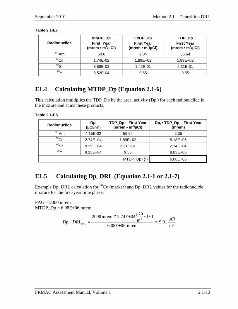
Table 2.1-E7
Radionuclide InhDP_Dp First Year
(mrem • m2/µCi)
ExDP_Dp First Year
(mrem • m2/µCi)
TDP_Dp First Year
(mrem • m2/µCi) 241Am 54.6 2.04 56.64 60Co 1.74E-02 1.89E+02 1.89E+02 90Sr 8.88E-02 1.42E-01 2.31E-01 90Y 8.52E-04 9.55 9.55
E1.4 Calculating MTDP_Dp (Equation 2.1-6) This calculation multiplies the TDP_Dp by the areal activity (Dpi) for each radionuclide in the mixture and sums these products.
Table 2.1-E8
Radionuclide Dpi (µCi/m2)
TDP_Dp – First Year (mrem • m2/µCi)
Dpi • TDP_Dp – First Year (mrem)
241Am 4.15E-02 56.64 2.35 60Co 2.74E+04 1.89E+02 5.18E+06 90Sr 9.25E+04 2.31E-01 2.14E+04 90Y 9.25E+04 9.55 8.83E+05
MTDP_Dp (∑) 6.08E+06
E1.5 Calculating Dp_DRL (Equation 2.1-1 or 2.1-7) Example Dp_DRL calculation for 60Co (marker) and Dp_DRL values for the radionuclide mixture for the first-year time phase.
PAG = 2000 mrem MTDP_Dp = 6.08E+06 mrem
Co
2
60 2
μCi2000mrem * 2.74E+04 1 1 μCim_ = 9.016.08E+06 mrem m
Dp DRL∗ ∗
=
September 2010 Method 2.1 – Deposition DRL
FRMAC Assessment Manual, Volume 1 2.1-14
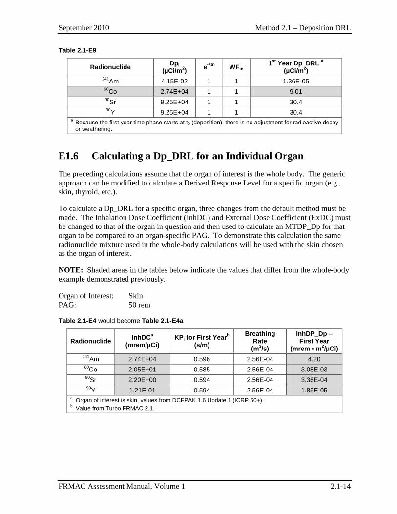
Table 2.1-E9
Radionuclide Dpi (µCi/m2) e-λtn WFtn 1st Year Dp_DRL a
(µCi/m2) 241Am 4.15E-02 1 1 1.36E-05 60Co 2.74E+04 1 1 9.01 90Sr 9.25E+04 1 1 30.4 90Y 9.25E+04 1 1 30.4
a Because the first year time phase starts at t0 (deposition), there is no adjustment for radioactive decay or weathering.
E1.6 Calculating a Dp_DRL for an Individual Organ The preceding calculations assume that the organ of interest is the whole body. The generic approach can be modified to calculate a Derived Response Level for a specific organ (e.g., skin, thyroid, etc.).
To calculate a Dp_DRL for a specific organ, three changes from the default method must be made. The Inhalation Dose Coefficient (InhDC) and External Dose Coefficient (ExDC) must be changed to that of the organ in question and then used to calculate an MTDP_Dp for that organ to be compared to an organ-specific PAG. To demonstrate this calculation the same radionuclide mixture used in the whole-body calculations will be used with the skin chosen as the organ of interest.
NOTE: Shaded areas in the tables below indicate the values that differ from the whole-body example demonstrated previously.
Organ of Interest: Skin PAG: 50 rem
Table 2.1-E4 would become Table 2.1-E4a
Radionuclide InhDCa (mrem/µCi)
KPi for First Yearb (s/m)
Breathing Rate
(m3/s)
InhDP_Dp – First Year
(mrem • m2/µCi) 241Am 2.74E+04 0.596 2.56E-04 4.20 60Co 2.05E+01 0.585 2.56E-04 3.08E-03 90Sr 2.20E+00 0.594 2.56E-04 3.36E-04 90Y 1.21E-01 0.594 2.56E-04 1.85E-05
a Organ of interest is skin, values from DCFPAK 1.6 Update 1 (ICRP 60+). b Value from Turbo FRMAC 2.1.
September 2010 Method 2.1 – Deposition DRL
FRMAC Assessment Manual, Volume 1 2.1-15
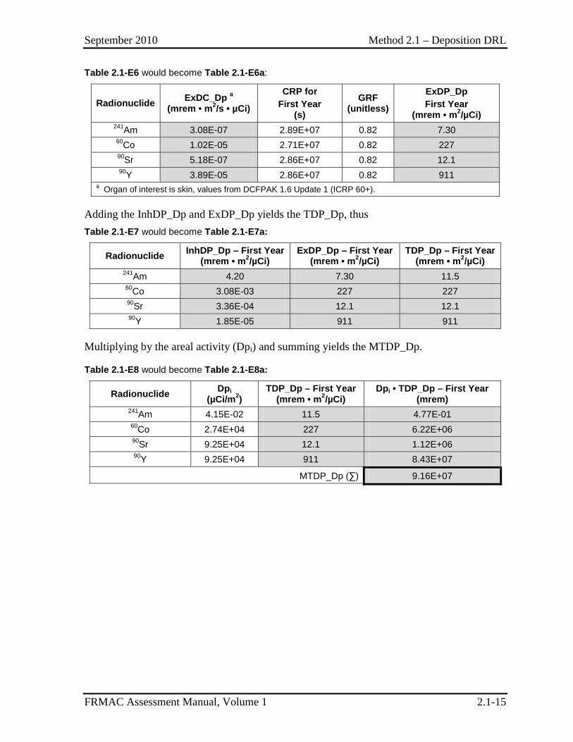
Table 2.1-E6 would become Table 2.1-E6a:
Radionuclide ExDC_Dp a (mrem • m2/s • µCi)
CRP for First Year
(s)
GRF (unitless)
ExDP_Dp First Year
(mrem • m2/µCi) 241Am 3.08E-07 2.89E+07 0.82 7.30 60Co 1.02E-05 2.71E+07 0.82 227 90Sr 5.18E-07 2.86E+07 0.82 12.1 90Y 3.89E-05 2.86E+07 0.82 911
a Organ of interest is skin, values from DCFPAK 1.6 Update 1 (ICRP 60+).
Adding the InhDP_Dp and ExDP_Dp yields the TDP_Dp, thus Table 2.1-E7 would become Table 2.1-E7a:
Radionuclide InhDP_Dp – First Year (mrem • m2/µCi)
ExDP_Dp – First Year (mrem • m2/µCi)
TDP_Dp – First Year (mrem • m2/µCi)
241Am 4.20 7.30 11.5 60Co 3.08E-03 227 227 90Sr 3.36E-04 12.1 12.1 90Y 1.85E-05 911 911
Multiplying by the areal activity (Dpi) and summing yields the MTDP_Dp.
Table 2.1-E8 would become Table 2.1-E8a:
Radionuclide Dpi (µCi/m2)
TDP_Dp – First Year (mrem • m2/µCi)
Dpi • TDP_Dp – First Year (mrem)
241Am 4.15E-02 11.5 4.77E-01 60Co 2.74E+04 227 6.22E+06 90Sr 9.25E+04 12.1 1.12E+06 90Y 9.25E+04 911 8.43E+07
MTDP_Dp (∑) 9.16E+07
September 2010 Method 2.1 – Deposition DRL
FRMAC Assessment Manual, Volume 1 2.1-16
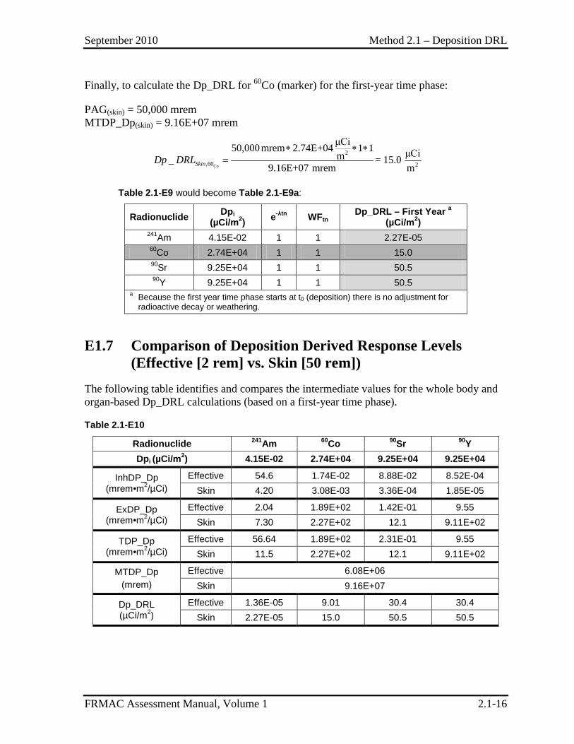
Finally, to calculate the Dp_DRL for 60Co (marker) for the first-year time phase:
PAG(skin) = 50,000 mrem MTDP_Dp(skin) = 9.16E+07 mrem
Co
2
,60 2
μCi50,000mrem 2.74E+04 1 1 μCim_ = 15.09.16E+07 mrem mSkinDp DRL
∗ ∗ ∗=
Table 2.1-E9 would become Table 2.1-E9a:
Radionuclide Dpi (µCi/m2) e-λtn WFtn Dp_DRL – First Year a
(µCi/m2) 241Am 4.15E-02 1 1 2.27E-05 60Co 2.74E+04 1 1 15.0 90Sr 9.25E+04 1 1 50.5 90Y 9.25E+04 1 1 50.5
a Because the first year time phase starts at t0 (deposition) there is no adjustment for radioactive decay or weathering.
E1.7 Comparison of Deposition Derived Response Levels (Effective [2 rem] vs. Skin [50 rem])
The following table identifies and compares the intermediate values for the whole body and organ-based Dp_DRL calculations (based on a first-year time phase).
Table 2.1-E10
Radionuclide 241Am 60Co 90Sr 90Y Dpi (µCi/m2) 4.15E-02 2.74E+04 9.25E+04 9.25E+04
InhDP_Dp (mrem•m2/µCi)
Effective 54.6 1.74E-02 8.88E-02 8.52E-04 Skin 4.20 3.08E-03 3.36E-04 1.85E-05
ExDP_Dp (mrem•m2/µCi)
Effective 2.04 1.89E+02 1.42E-01 9.55 Skin 7.30 2.27E+02 12.1 9.11E+02
TDP_Dp (mrem•m2/µCi)
Effective 56.64 1.89E+02 2.31E-01 9.55 Skin 11.5 2.27E+02 12.1 9.11E+02
MTDP_Dp (mrem)
Effective 6.08E+06 Skin 9.16E+07
Dp_DRL (µCi/m2)
Effective 1.36E-05 9.01 30.4 30.4 Skin 2.27E-05 15.0 50.5 50.5
September 2010 Method 2.2 – Deposition Dose and Exposure Rate DRLs
FRMAC Assessment Manual, Volume 1 2.2-1
METHOD 2.2 DEPOSITION DOSE AND EXPOSURE RATE DERIVED RESPONSE LEVELS
Application This method has been developed to calculate a Deposition Dose Rate Derived Response Level (Dp_DRLDR) and Deposition Exposure Rate Derived Response Level (Dp_DRLXR) for a deposition of radioactive material.
The Dp_DRLDR:
• Represents the dose rate (mrem/hr, measured at 1 m above the ground) at a given time (tn), from all radionuclides in a deposition mixture that will be expected to produce a dose equal to the appropriate Protective Action Guide (PAG) over the time phase under consideration.
The Dp_DRLXR:
• Represents the exposure rate (mR/hr, measured at 1 m above the ground) at a given time (tn), from all radionuclides in a deposition mixture that will be expected to produce a dose equal to the appropriate Protective Action Guide (PAG) over the time phase under consideration.
Both the Dp_DRLDR and the Dp_DRLXR are:
• Derived from the PAGs for radiological emergency planning established by the Environmental Protection Agency (EPA) (EPA92) or the Department of Homeland Security (DHS) (DHS08). A projected or measured rate value greater than the DRL indicates that the PAG has the potential to be exceeded.
• Used to create data products and define dose and/or exposure rates to assist decision makers in determining where implementing protective actions (e.g., sheltering, evacuation, relocation) may be advisable.
• Calculated using the Mixture Total Dose Parameter for Deposition (MTDP_Dp) value calculated in Method 2.1.
Discussion These DRLs relate a measured dose (or exposure) rate to the total of the external dose from material deposited on the ground (i.e., groundshine) and the dose from the inhalation of resuspended material.
September 2010 Method 2.2 – Deposition Dose and Exposure Rate DRLs
FRMAC Assessment Manual, Volume 1 2.2-2
These DRLs combine an External Dose Factor (ExDF) with the deposition (areal activity) values for each radionuclide present in a mixture and relates that product (MExDF_Dp) to the PAG for the time phase under consideration and the Mixture Total Dose Parameter for Deposition (MTDP_Dp – calculated in Method 2.1) to calculate the Dp_DRLDR. The Dp_DRLXR is then obtained by dividing the Dp_DRLDR by an Exposure to Dose Conversion Factor (XDCF).
These DRLs are based on the ratio of activities of each radionuclide in a mixture, not the individual activity values of those radionuclides.
Assumptions There are no additional assumptions beyond the default assumptions.
Inputs In addition to the default inputs, the following information is required to perform the calculations described in this method:
Mixture Total Dose Parameter for Deposition (MTDP_Dp) – Calculated using Method 2.1.
If incident-specific values have not been established, recommended default values for selected inputs are available in Appendix C.
Outputs The final output of this method is the Dp_DRLDR or Dp_DRLXR for a deposition of radioactive material.
Final
Dp_DRLDR = Deposition Dose Rate Derived Response Level, the external dose rate, at time tn, at which the dose from all radionuclides in a deposition mixture would result in a dose equal to the PAG for the time phase under consideration, mrem/hr
Dp_DRLXR = Deposition Exposure Rate Derived Response Level, the external exposure rate, at time tn, at which the dose from all radionuclides in a deposition mixture would result in a dose equal to the PAG for the time phase under consideration, mR/hr
September 2010 Method 2.2 – Deposition Dose and Exposure Rate DRLs
FRMAC Assessment Manual, Volume 1 2.2-3
Intermediate
The following intermediate values may be referenced in other methods and are called out here for clarity.
ExDF_Dp = External Dose Factor for deposition for each radionuclide in the mixture of interest (mrem/hr per µCi/m2)
MExDF_Dp = Mixture External Dose Factor for all radionuclides in the mixture of interest (mR/hr)
Method 2.2.1 Deposition Dose Rate Derived Response Level (Dp_DRLDR)
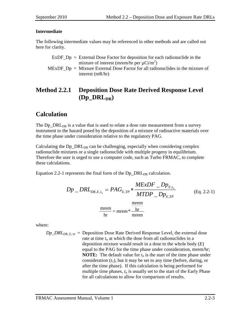
Calculation The Dp_DRLDR is a value that is used to relate a dose rate measurement from a survey instrument to the hazard posed by the deposition of a mixture of radioactive materials over the time phase under consideration relative to the regulatory PAG.
Calculating the Dp_DRLDR can be challenging, especially when considering complex radionuclide mixtures or a single radionuclide with multiple progeny in equilibrium. Therefore the user is urged to use a computer code, such as Turbo FRMAC, to complete these calculations.
Equation 2.2-1 represents the final form of the Dp_DRLDR calculation.
,
, , ,,
__
_= ∗ n
n
E tDR E t E TP
E TP
MExDF DpDp DRL PAG
MTDP Dp (Eq. 2.2-1)
mremmrem hr= mrem*
hr mrem
where:
Dp_DRLDR, E, tn = Deposition Dose Rate Derived Response Level, the external dose rate at time tn at which the dose from all radionuclides in a deposition mixture would result in a dose to the whole body (E) equal to the PAG for the time phase under consideration, mrem/hr; NOTE: The default value for tn is the start of the time phase under consideration (t1), but it may be set to any time (before, during, or after the time phase). If this calculation is being performed for multiple time phases, tn is usually set to the start of the Early Phase for all calculations to allow for comparison of results.
September 2010 Method 2.2 – Deposition Dose and Exposure Rate DRLs
FRMAC Assessment Manual, Volume 1 2.2-4
PAGE,TP = Protective Action Guide, as specified by the EPA or local authorities, for the whole body (E), for the time phase (TP) under consideration, mrem;
MExDF_DpE,tn = Mixture External Dose Factor for Deposition, the external dose rate received by the whole body (E) at time tn, from a radionuclide mixture deposited on the ground, mrem/hr; and
MTDP_DpE,TP = Mixture Total Dose Parameter for Deposition (See Method 2.1), mrem.
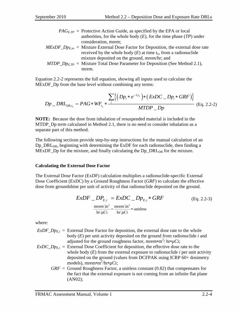
Equation 2.2-2 represents the full equation, showing all inputs used to calculate the MExDF_Dp from the base level without combining any terms:
( ) ( ){ }
,
__
_
λ−∗ ∗ ∗= ∗ ∗
∑ i n
n n
ti i
iDR t t
Dp e ExDC Dp GRFDp DRL PAG WF
MTDP Dp(Eq. 2.2-2)
NOTE: Because the dose from inhalation of resuspended material is included in the MTDP_Dp term calculated in Method 2.1, there is no need to consider inhalation as a separate part of this method.
The following sections provide step-by-step instructions for the manual calculation of an Dp_DRLDR, beginning with determining the ExDF for each radionuclide, then finding a MExDF_Dp for the mixture, and finally calculating the Dp_DRLDR for the mixture.
Calculating the External Dose Factor
The External Dose Factor (ExDF) calculation multiplies a radionuclide-specific External Dose Coefficient (ExDC) by a Ground Roughness Factor (GRF) to calculate the effective dose from groundshine per unit of activity of that radionuclide deposited on the ground.
, ,_ _= ∗E i E iExDF DP ExDC Dp GRF (Eq. 2.2-3)
2 2mrem m mrem m= unitless
hr μCi hr μCi∗
where:
ExDF_DpE,i = External Dose Factor for deposition, the external dose rate to the whole body (E) per unit activity deposited on the ground from radionuclide i and adjusted for the ground roughness factor, mrem•m2/ hr•µCi;
ExDC_DpE,i = External Dose Coefficient for deposition, the effective dose rate to the whole body (E) from the external exposure to radionuclide i per unit activity deposited on the ground (values from DCFPAK using ICRP 60+ dosimetry models), mrem•m2/hr•µCi;
GRF = Ground Roughness Factor, a unitless constant (0.82) that compensates for the fact that the external exposure is not coming from an infinite flat plane (AN02);
September 2010 Method 2.2 – Deposition Dose and Exposure Rate DRLs
FRMAC Assessment Manual, Volume 1 2.2-5
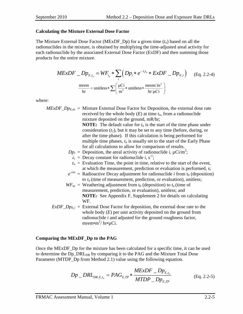
Calculating the Mixture External Dose Factor
The Mixture External Dose Factor (MExDF_Dp) for a given time (tn) based on all the radionuclides in the mixture, is obtained by multiplying the time-adjusted areal activity for each radionuclide by the associated External Dose Factor (ExDF) and then summing those products for the entire mixture.
( ), ,_ _λ−= ∗ ∗ ∗∑ i n
n n
tE t t i E i
iMExDF Dp WF Dp e ExDF Dp (Eq. 2.2-4)
2
2
mrem μCi mrem munitless unitlesshr m hr μCi
= ∗ ∗ ∗
∑
where:
MExDF_DpE,tn = Mixture External Dose Factor for Deposition, the external dose rate received by the whole body (E) at time tn, from a radionuclide mixture deposited on the ground, mR/hr; NOTE: The default value for tn is the start of the time phase under consideration (t1), but it may be set to any time (before, during, or after the time phase). If this calculation is being performed for multiple time phases, tn is usually set to the start of the Early Phase for all calculations to allow for comparison of results.
Dpi = Deposition, the areal activity of radionuclide i, µCi/m2; λi = Decay constant for radionuclide i, s-1; tn = Evaluation Time, the point in time, relative to the start of the event,
at which the measurement, prediction or evaluation is performed, s; e-λtn = Radioactive Decay adjustment for radionuclide i from t0 (deposition)
to tn (time of measurement, prediction, or evaluation), unitless; WFtn = Weathering adjustment from t0 (deposition) to tn (time of
measurement, prediction, or evaluation), unitless; and NOTE: See Appendix F, Supplement 2 for details on calculating WF.
ExDF_DpE,i = External Dose Factor for deposition, the external dose rate to the whole body (E) per unit activity deposited on the ground from radionuclide i and adjusted for the ground roughness factor, mrem•m2/ hr•µCi.
Comparing the MExDF_Dp to the PAG
Once the MExDF_Dp for the mixture has been calculated for a specific time, it can be used to determine the Dp_DRLDR by comparing it to the PAG and the Mixture Total Dose Parameter (MTDP_Dp from Method 2.1) value using the following equation.
,
, , ,,
__
_= ∗ n
n
E tDR E t E TP
E TP
MExDF DpDp DRL PAG
MTDP Dp (Eq. 2.2-5)
September 2010 Method 2.2 – Deposition Dose and Exposure Rate DRLs
FRMAC Assessment Manual, Volume 1 2.2-6
mrem
mrem hrmremhr mrem
= ∗
where:
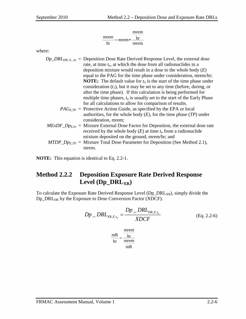
Dp_DRLDR, E, ,tn = Deposition Dose Rate Derived Response Level, the external dose rate, at time tn, at which the dose from all radionuclides in a deposition mixture would result in a dose to the whole body (E) equal to the PAG for the time phase under consideration, mrem/hr;
NOTE: The default value for tn is the start of the time phase under consideration (t1), but it may be set to any time (before, during, or after the time phase). If this calculation is being performed for multiple time phases, tn is usually set to the start of the Early Phase for all calculations to allow for comparison of results.
PAGE,TP = Protective Action Guide, as specified by the EPA or local authorities, for the whole body (E), for the time phase (TP) under consideration, mrem;
MExDF_DpE,tn = Mixture External Dose Factor for Deposition, the external dose rate received by the whole body (E) at time tn from a radionuclide mixture deposited on the ground, mrem/hr; and
MTDP_DpE,TP = Mixture Total Dose Parameter for Deposition (See Method 2.1), mrem.
NOTE: This equation is identical to Eq. 2.2-1.
Method 2.2.2 Deposition Exposure Rate Derived Response Level (Dp_DRLXR)
To calculate the Exposure Rate Derived Response Level (Dp_DRLXR), simply divide the Dp_DRLDR by the Exposure to Dose Conversion Factor (XDCF).
, ,
, ,
__ = n
n
DR E tXR E t
Dp DRLDp DRL
XDCF (Eq. 2.2-6)
mrem
mR hrmremhrmR
=
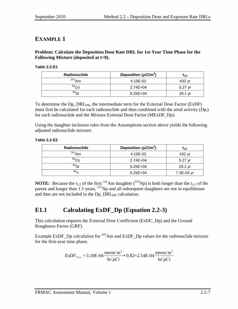
September 2010 Method 2.2 – Deposition Dose and Exposure Rate DRLs
FRMAC Assessment Manual, Volume 1 2.2-7
EXAMPLE 1
Problem: Calculate the Deposition Dose Rate DRL for 1st-Year Time Phase for the Following Mixture (deposited at t=0).
Table 2.2-E1
Radionuclide Deposition (μCi/m2) t1/2 241Am 4.15E-02 432 yr 60Co 2.74E+04 5.27 yr 90Sr 9.25E+04 29.1 yr
To determine the Dp_DRLDR, the intermediate term for the External Dose Factor (ExDF) must first be calculated for each radionuclide and then combined with the areal activity (Dpi) for each radionuclide and the Mixture External Dose Factor (MExDF_Dp).
Using the daughter inclusion rules from the Assumptions section above yields the following adjusted radionuclide mixture:
Table 2.2-E2
Radionuclide Deposition (μCi/m2) t1/2 241Am 4.15E-02 432 yr 60Co 2.74E+04 5.27 yr 90Sr 9.25E+04 29.1 yr 90Y 9.25E+04 7.3E-03 yr
NOTE: Because the t1/2 of the first 241Am daughter (237Np) is both longer than the t1/2 of the parent and longer than 1.5 years, 237Np and all subsequent daughters are not in equilibrium and thus are not included in the Dp_DRLDR calculation.
E1.1 Calculating ExDF_Dp (Equation 2.2-3) This calculation requires the External Dose Coefficient (ExDC_Dp) and the Ground Roughness Factor (GRF).
Example ExDF_Dp calculation for 241Am and ExDF_Dp values for the radionuclide mixture for the first-year time phase.
241
2 2mrem m mrem m=3.10E-04 0.82=2.54E-04hr μCi hr μCi
∗
AmExDF
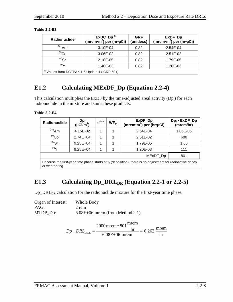
September 2010 Method 2.2 – Deposition Dose and Exposure Rate DRLs
FRMAC Assessment Manual, Volume 1 2.2-8
Table 2.2-E3
Radionuclide ExDC_Dp a (mrem•m2) per (hr•µCi)
GRF (unitless)
ExDF_Dp (mrem•m2) per (hr•µCi)
241Am 3.10E-04 0.82 2.54E-04 60Co 3.06E-02 0.82 2.51E-02 90Sr 2.18E-05 0.82 1.79E-05 90Y 1.46E-03 0.82 1.20E-03
a Values from DCFPAK 1.6 Update 1 (ICRP 60+).
E1.2 Calculating MExDF_Dp (Equation 2.2-4) This calculation multiplies the ExDF by the time-adjusted areal activity (Dpi) for each radionuclide in the mixture and sums these products.
Table 2.2-E4
Radionuclide Dpi (µCi/m2) e-λtn WFtn ExDF_Dp
(mrem•m2) per (hr•µCi) Dpi • ExDF_Dp
(mrem/hr) 241Am 4.15E-02 1 1 2.54E-04 1.05E-05 60Co 2.74E+04 1 1 2.51E-02 688 90Sr 9.25E+04 1 1 1.79E-05 1.66 90Y 9.25E+04 1 1 1.20E-03 111
MExDF_Dp 801 Because the first-year time phase starts at t0 (deposition), there is no adjustment for radioactive decay or weathering.
E1.3 Calculating Dp_DRLDR (Equation 2.2-1 or 2.2-5) Dp_DRLDR calculation for the radionuclide mixture for the first-year time phase.
Organ of Interest: Whole Body PAG: 2 rem MTDP_Dp: 6.08E+06 mrem (from Method 2.1)
,
mrem2000mrem 801 mremhr_ 0.2636.08E+06 mrem hr
∗= =DR EDp DRL
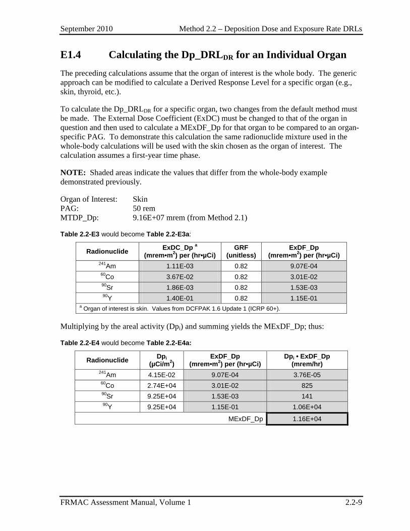
September 2010 Method 2.2 – Deposition Dose and Exposure Rate DRLs
FRMAC Assessment Manual, Volume 1 2.2-9
E1.4 Calculating the Dp_DRLDR for an Individual Organ The preceding calculations assume that the organ of interest is the whole body. The generic approach can be modified to calculate a Derived Response Level for a specific organ (e.g., skin, thyroid, etc.).
To calculate the Dp_DRLDR for a specific organ, two changes from the default method must be made. The External Dose Coefficient (ExDC) must be changed to that of the organ in question and then used to calculate a MExDF_Dp for that organ to be compared to an organ-specific PAG. To demonstrate this calculation the same radionuclide mixture used in the whole-body calculations will be used with the skin chosen as the organ of interest. The calculation assumes a first-year time phase.
NOTE: Shaded areas indicate the values that differ from the whole-body example demonstrated previously.
Organ of Interest: Skin PAG: 50 rem MTDP_Dp: 9.16E+07 mrem (from Method 2.1)
Table 2.2-E3 would become Table 2.2-E3a:
Radionuclide ExDC_Dp a
(mrem•m2) per (hr•µCi) GRF
(unitless) ExDF_Dp
(mrem•m2) per (hr•µCi) 241Am 1.11E-03 0.82 9.07E-04 60Co 3.67E-02 0.82 3.01E-02 90Sr 1.86E-03 0.82 1.53E-03 90Y 1.40E-01 0.82 1.15E-01
a Organ of interest is skin. Values from DCFPAK 1.6 Update 1 (ICRP 60+).
Multiplying by the areal activity (Dpi) and summing yields the MExDF_Dp; thus:
Table 2.2-E4 would become Table 2.2-E4a:
Radionuclide Dpi (µCi/m2)
ExDF_Dp (mrem•m2) per (hr•µCi)
Dpi • ExDF_Dp (mrem/hr)
241Am 4.15E-02 9.07E-04 3.76E-05 60Co 2.74E+04 3.01E-02 825 90Sr 9.25E+04 1.53E-03 141 90Y 9.25E+04 1.15E-01 1.06E+04
MExDF_Dp 1.16E+04
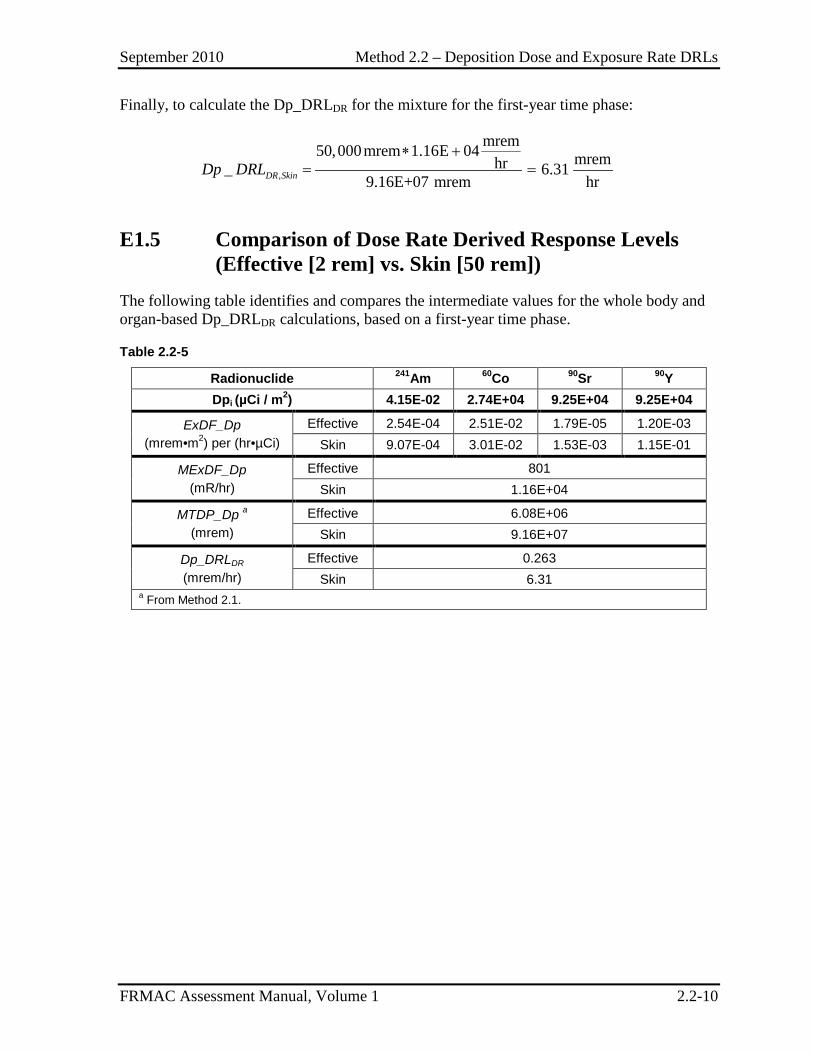
September 2010 Method 2.2 – Deposition Dose and Exposure Rate DRLs
FRMAC Assessment Manual, Volume 1 2.2-10
Finally, to calculate the Dp_DRLDR for the mixture for the first-year time phase:
,
mrem50,000mrem 1.16E 04 mremhr_ 6.319.16E+07 mrem hr
∗ += =DR SkinDp DRL
E1.5 Comparison of Dose Rate Derived Response Levels (Effective [2 rem] vs. Skin [50 rem])
The following table identifies and compares the intermediate values for the whole body and organ-based Dp_DRLDR calculations, based on a first-year time phase.
Table 2.2-5
Radionuclide 241Am 60Co 90Sr 90Y Dpi (µCi / m2) 4.15E-02 2.74E+04 9.25E+04 9.25E+04
ExDF_Dp (mrem•m2) per (hr•µCi)
Effective 2.54E-04 2.51E-02 1.79E-05 1.20E-03 Skin 9.07E-04 3.01E-02 1.53E-03 1.15E-01
MExDF_Dp (mR/hr)
Effective 801 Skin 1.16E+04
MTDP_Dp a (mrem)
Effective 6.08E+06 Skin 9.16E+07
Dp_DRLDR (mrem/hr)
Effective 0.263 Skin 6.31
a From Method 2.1.
September 2010 Method 2.3 – Deposition Alpha DRL
FRMAC Assessment Manual, Volume 1 2.3-1
METHOD 2.3 DEPOSITION ALPHA DERIVED RESPONSE LEVEL
Application This method has been developed to calculate a Deposition Alpha Derived Response Level (Dp_DRLα) for a deposition of radioactive material.
The Dp_DRLα:
• Represents the ground concentration, or areal alpha activity (µCi/m2), at a given time (tn) of a mixture of radionuclides that will be expected to cause the mixture to produce a dose equal to the appropriate Protective Action Guide (PAG) over the time phase under consideration.
• Is derived from the PAGs for radiological emergency planning established by the Environmental Protection Agency (EPA) (EPA92) or the Department of Homeland Security (DHS) (DHS08). A projected or measured deposition value greater than the Dp_DRLα indicates that the PAG has the potential to be exceeded.
• Is used to create data products and define areal alpha activity to assist decision makers in determining where it may be advisable to implement protective actions (e.g., sheltering, evacuation, relocation).
• Is calculated using the Deposition Derived Response Level (Dp_DRL) value calculated in Method 2.1.
Because it is difficult to foresee what instruments will be used by monitoring personnel, it not appropriate for the FRMAC Assessment Division to calculate instrument-specific Alpha DRLs in units of counts per minute (cpm) per a given probe area (e.g., 550 α cpm/100 cm2) for a given radionuclide mixture. Rather, the value calculated by this method is an intermediate value and must be adjusted for conditions in the field (e.g., instrument efficiency, surface conditions, and environmental conditions).
The FRMAC Monitoring and Sampling Division is responsible for converting their monitoring and sampling data from cpm/probe area into assessment units (µCi/m2) that can be compared with the values calculated by this method.
Discussion The Dp_DRLα is a value obtained by multiplying the calculated Dp_DRL for each radionuclide present in a mixture by the alpha yield (Yα, alpha activity per nuclear transformation) and then summing those products over the entire mixture. Because the Dp_DRL for each radionuclide is determined using a regulatory PAG, this summation represents the number of “alpha events” that would indicate the presence of a mixture of radionuclides that would cause an individual to receive a dose equal to the PAG.
September 2010 Method 2.3 – Deposition Alpha DRL
FRMAC Assessment Manual, Volume 1 2.3-2
Calculating a Dp_DRLα for a single radionuclide or a radionuclide mixture is complicated by factors that affect the detection efficiency (alpha counts per nuclear transformation), including:
• Energy variance: varying energies (and corresponding efficiencies) of alpha emissions from different radionuclides;
• Self-absorption: the alpha detection efficiency is likely to be lower for clumps of source material than for finely divided source material;
• Surface characteristics: e.g., soil, pavement, and grass, because these factors affect the fraction of the alpha radiation that is shielded; and
• Environmental conditions: e.g., rain and dust, due to shielding effects.
Field monitoring instruments can often distinguish between alpha radiation and other forms of radiations (e.g., β-) due to the detector’s signal-discriminating capabilities. However it can still be difficult to determine the magnitude of the detector’s response that is due solely to alpha radiation because of confounding factors, including:
• Crosstalk: Many field monitoring instruments that detect alpha radiation also detect beta radiation and there is some crosstalk between the scalars for the different radiation types. Therefore, in an alpha and beta radiation field, a fraction of the alpha signal will actually be due to beta radiation.
• Gamma Interference: Some types (e.g., scintillation, Geiger-Mueller) of field monitoring instruments that detect alpha radiation also detect gamma radiation and some of these instruments (e.g., Geiger-Mueller) are not able to distinguish between these radiation types. Although the gamma detection efficiency is typically much lower than the alpha detection efficiency, the ability of an alpha detector to reliably quantify only the alpha radiation signal may be significantly compromised in areas with a high gamma radiation component.
• Neutron Interference: Some types (e.g., scintillation) of field monitoring instruments that detect alpha radiation also detect neutron radiation and some of these instruments are not able to distinguish between these radiation types. Therefore the ability of an alpha detector to reliably quantify only the alpha radiation signal may be significantly compromised in areas with a high neutron radiation component.
Assumptions The following assumptions apply in addition to the default assumptions:
This method assumes that detection efficiencies and probe area correction factors will be applied by Monitoring and Sampling Division personnel for the specific instrumentation used in the field.
September 2010 Method 2.3 – Deposition Alpha DRL
FRMAC Assessment Manual, Volume 1 2.3-3
Inputs In addition to the default inputs, the following information is used to perform the calculations described in this method:
• Deposition Derived Response Level (Dp_DRL) for each radionuclide in the mixture – Calculated using Method 2.1.
• Alpha Yield, the alpha activity per total (nuclear transformation) activity of radionuclide i, μCiα/μCint.
If incident-specific values have not been established, recommended default values for selected inputs are available in Appendix C.
Outputs The final output of this method is the Alpha Derived Response Level for a deposition of radioactive material.
Final
Dp_DRLα = Deposition Alpha Derived Response Level, the areal alpha activity at time tn of the mixture at which the dose from all radionuclides in a deposition mixture would result in a dose equal to the PAG for the time phase under consideration, μCiα/m2.
Intermediate
The following intermediate values may be referenced in other methods and are called out here for clarity.
None
Calculation The calculation of the Dp_DRLα determines the areal alpha activity of the mixture at which the dose from all radionuclides in the mixture would result in a dose equal to the PAG for the time phase under consideration.
The FRMAC Assessment Division uses the following method to calculate the Dp_DRLα values. The FRMAC Monitoring & Sampling Division will compare the sampling and monitoring data to the respective DRL to determine if the PAG for the time phase under consideration has been exceeded.
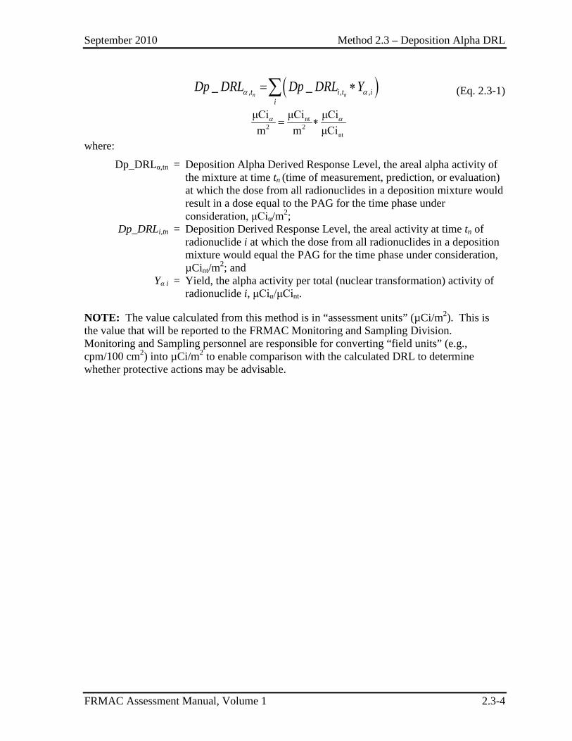
September 2010 Method 2.3 – Deposition Alpha DRL
FRMAC Assessment Manual, Volume 1 2.3-4
( ), , ,_ _α α= ∗∑n nt i t ii
Dp DRL Dp DRL Y (Eq. 2.3-1)
nt2 2
nt
μCi μCi μCim m μCi
α α= ∗
where:
Dp_DRLα,tn = Deposition Alpha Derived Response Level, the areal alpha activity of the mixture at time tn (time of measurement, prediction, or evaluation) at which the dose from all radionuclides in a deposition mixture would result in a dose equal to the PAG for the time phase under consideration, μCiα/m2;
Dp_DRLi,tn = Deposition Derived Response Level, the areal activity at time tn of radionuclide i at which the dose from all radionuclides in a deposition mixture would equal the PAG for the time phase under consideration, µCint/m2; and
Yα i = Yield, the alpha activity per total (nuclear transformation) activity of radionuclide i, μCiα/μCint.
NOTE: The value calculated from this method is in “assessment units” (µCi/m2). This is the value that will be reported to the FRMAC Monitoring and Sampling Division. Monitoring and Sampling personnel are responsible for converting “field units” (e.g., cpm/100 cm2) into µCi/m2 to enable comparison with the calculated DRL to determine whether protective actions may be advisable.
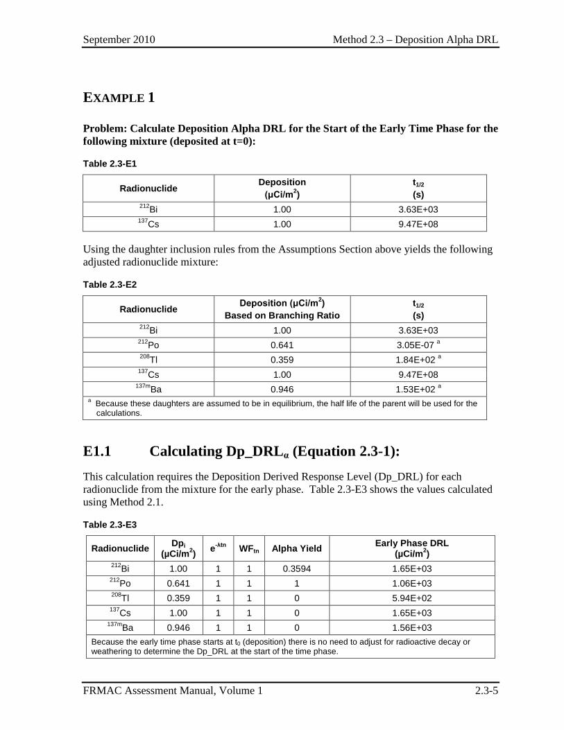
September 2010 Method 2.3 – Deposition Alpha DRL
FRMAC Assessment Manual, Volume 1 2.3-5
EXAMPLE 1
Problem: Calculate Deposition Alpha DRL for the Start of the Early Time Phase for the following mixture (deposited at t=0):
Table 2.3-E1
Radionuclide Deposition (μCi/m2)
t1/2
(s) 212Bi 1.00 3.63E+03 137Cs 1.00 9.47E+08
Using the daughter inclusion rules from the Assumptions Section above yields the following adjusted radionuclide mixture:
Table 2.3-E2
Radionuclide Deposition (μCi/m2) Based on Branching Ratio
t1/2
(s) 212Bi 1.00 3.63E+03 212Po 0.641 3.05E-07 a 208Tl 0.359 1.84E+02 a
137Cs 1.00 9.47E+08 137mBa 0.946 1.53E+02 a
a Because these daughters are assumed to be in equilibrium, the half life of the parent will be used for the calculations.
E1.1 Calculating Dp_DRLα (Equation 2.3-1): This calculation requires the Deposition Derived Response Level (Dp_DRL) for each radionuclide from the mixture for the early phase. Table 2.3-E3 shows the values calculated using Method 2.1.
Table 2.3-E3
Radionuclide Dpi (µCi/m2) e-λtn WFtn Alpha Yield Early Phase DRL
(µCi/m2) 212Bi 1.00 1 1 0.3594 1.65E+03 212Po 0.641 1 1 1 1.06E+03 208Tl 0.359 1 1 0 5.94E+02
137Cs 1.00 1 1 0 1.65E+03 137mBa 0.946 1 1 0 1.56E+03
Because the early time phase starts at t0 (deposition) there is no need to adjust for radioactive decay or weathering to determine the Dp_DRL at the start of the time phase.
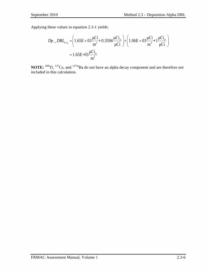
September 2010 Method 2.3 – Deposition Alpha DRL
FRMAC Assessment Manual, Volume 1 2.3-6
Applying these values in equation 2.3-1 yields:
0
α α, 2 2
α2
μCi μCiμCi μCi_ 1.65E 03 0.3594 1.06E 03 1m μCi m μCi
μCi1.65E+03m
α
= + ∗ + + ∗
=
tDp DRL
NOTE: 208Tl, 137Cs, and 137mBa do not have an alpha decay component and are therefore not included in this calculation.
September 2010 Method 2.4 – Deposition Beta DRL
FRMAC Assessment Manual, Volume 1 2.4-1
METHOD 2.4 DEPOSITION BETA DERIVED RESPONSE LEVEL
Application This method has been developed to calculate a Deposition Beta Derived Response Level (Dp_DRLβ-) for a deposition of radioactive material.
The Dp_DRLβ-:
• Represents the ground concentration, or areal beta activity (µCi/m2), at a given time (tn) of a mixture of radionuclides that will be expected to cause the mixture to produce a dose equal to the appropriate Protective Action Guide (PAG) over the time phase under consideration.
• Is derived from the PAGs for radiological emergency planning established by the Environmental Protection Agency (EPA) (EPA92) or the Department of Homeland Security (DHS) (DHS08). A projected or measured deposition value greater than the Dp_DRLβ- indicates that the PAG has the potential to be exceeded.
• Is used to create data products and define areal beta activity to assist decision makers in determining where it may be advisable to implement protective actions (e.g., sheltering, evacuation, relocation).
• Is calculated using the Deposition Derived Response Level (Dp_DRL) value calculated in Method 2.1.
Because it is difficult to foresee what instruments will be used by monitoring personnel, it not appropriate for the FRMAC Assessment Division to calculate instrument-specific Beta DRLs in units of counts per minute (cpm) per a given probe area (e.g., 550 β- cpm/100 cm2) for a given radionuclide mixture. Rather, the value calculated by this method is an intermediate value and must be adjusted for conditions in the field (e.g., instrument efficiency, surface conditions, and environmental conditions).
The FRMAC Monitoring and Sampling Division is responsible for converting their monitoring and sampling data from cpm/probe area into assessment units (µCi/m2) that can be compared with the values calculated by this method.
Discussion The Dp_DRLβ- is a value obtained by multiplying the calculated Dp_DRL for each radionuclide present in a mixture by the beta yield (Yβ, beta activity per nuclear transformation) and then summing those products over the entire mixture. Because the Dp_DRL for each radionuclide is determined using a regulatory PAG, this summation represents the number of “beta events” that would indicate the presence of a mixture of radionuclides that would cause an individual to receive a dose equal to the PAG.
September 2010 Method 2.4 – Deposition Beta DRL
FRMAC Assessment Manual, Volume 1 2.4-2
Calculating a Dp_DRLβ- for a single radionuclide or a radionuclide mixture is complicated by factors that affect the detection efficiency (beta counts per nuclear transformation), including:
• Beta decay spectrum: beta particles are emitted over an energy range from zero up to a maximum value that is characteristic of the excited nucleus. Some fraction of the beta particles emitted by a radionuclide is not detectable because the beta particles lack sufficient energy to penetrate the detector’s window and are unable to enter the detector’s sensitive volume. Therefore there is a threshold energy below which beta particles are not detectable;
NOTE: FRMAC Assessment uses a default energy threshold of 70 kev (roughly the stopping power of one layer of Mylar® film) to determine which decays to include. This threshold can be modified in the Turbo FRMAC software package to address different instrument detection capabilities.
• Energy variance: varying maximum energies (and corresponding efficiencies) of beta emissions from different radionuclides;
• Detector characteristics: The mass thickness (mg/cm2) of the detector’s window and walls varies between detector types and manufacturers. Therefore the detectable fraction of the beta particle energy spectrum varies with the detector and with the window condition (i.e., open vs. closed);
• Surface characteristics: e.g., soil, pavement, and grass, because these factors affect the fraction of the beta radiation that is shielded or backscattered; and
• Environmental conditions: e.g., rain and dust, due to shielding effects. NOTE: The Turbo FRMAC software package and the associated DCFPAK database include contributions from standard beta decay as well as other modes of decay (e.g., internal conversion electrons) that produce particles that would be interpreted by detectors as “beta decay.” Each of these decay modes is included in the Dp_DRLβ- calculation for all decays that could be detected by an instrument. Field monitoring instruments that detect beta radiation are often capable of detecting other forms of ionizing radiation (e.g., gamma radiation), but are unable to distinguish between these different radiation types. Therefore it can be difficult to determine the magnitude of the detector’s response that is due solely to beta radiation. Some of the confounding factors include:
• Crosstalk: Many field monitoring instruments that detect beta radiation also detect alpha radiation and there is some crosstalk between the scalars for the different radiation types. Therefore, in an alpha and beta radiation field, a fraction of the beta signal will actually be due to alpha radiation.
• Gamma Interference: Conventional field instruments typically cannot distinguish between beta particles and gamma radiation. Some types (e.g., scintillation) of beta-radiation detectors have higher gamma detection efficiencies than other types (e.g., thin-walled gas-filled). Although the gamma detection efficiency is typically much lower than the beta detection efficiency, the ability of a beta detector to reliably
September 2010 Method 2.4 – Deposition Beta DRL
FRMAC Assessment Manual, Volume 1 2.4-3
quantify only the beta radiation signal may be significantly compromised in areas with a high gamma radiation component.
• Neutron Interference: Some types (e.g., scintillation) of field monitoring instruments that detect beta radiation also detect neutron radiation and some of these instruments are not able to distinguish between these radiation types. Therefore, the ability of a beta detector to reliably quantify only the beta radiation signal may be significantly compromised in areas with a high neutron radiation component.
• Many radionuclides that undergo beta decay also emit Auger electrons and fluorescence photons at various energies. These emissions may produce spurious pulses in a typical beta radiation field monitoring instruments.
Assumptions The following assumptions apply in addition to the default assumptions:
This method assumes that detection efficiencies and probe area correction factors will be applied by Monitoring and Sampling Division personnel for the specific instrumentation used in the field.
Inputs In addition to the default inputs, the following information is required to perform the calculations described in this method:
• Deposition Derived Response Level (Dp_DRL) for each radionuclide in the mixture – Calculated using Method 2.1.
• Beta Yield, the beta activity per total (nuclear transformation) activity of radionuclide i, μCiβ/μCint.
If incident-specific values have not been established, recommended default values for selected inputs are available in Appendix C.
Outputs The final output of this method is the Beta Derived Response Level for a deposition of radioactive material.
Final
Dp_DRLβ- = Deposition Beta Derived Response Level, the areal beta activity at time tn of the mixture at which the dose from all radionuclides in a deposition mixture would result in a dose equal to the PAG for the time phase under consideration, μCiβ/m2
September 2010 Method 2.4 – Deposition Beta DRL
FRMAC Assessment Manual, Volume 1 2.4-4
Intermediate
The following intermediate values may be referenced in other methods and are called out here for clarity.
None
Calculation The calculation of the Dp_DRLβ- determines the areal beta activity of the mixture at which the dose from all radionuclides in the mixture would result in a dose equal to the PAG for the time phase under consideration.
The FRMAC Assessment Division uses the following method to calculate the Dp_DRLβ- values. The FRMAC Monitoring & Sampling Division will compare the sampling and monitoring data to the respective DRL to determine if the PAG for the time phase under consideration has been exceeded.
( ), , ,_ _β β −− = ∗∑n nt i t i
iDp DRL Dp DRL Y (Eq. 2.4-1)
nt2 2
nt
μCi μCiμCim m μCi
β β− −
= ∗
where:
Dp_DRLβ-,tn = Deposition Beta Derived Response Level, the areal beta activity of the mixture, at time tn at which the dose from all radionuclides in a deposition mixture would result in a dose equal to the PAG for the time phase under consideration, μCiβ/m2;
Dp_DRLi,tn = Deposition Derived Response Level, the areal activity, at time tn of radionuclide i at which the dose from all radionuclides in a deposition mixture would equal the PAG for the time phase under consideration, µCint/m2; and
Yβ i = Yield, the beta activity per total (nuclear transformation) activity of radionuclide i, μCiβ/μCint.
NOTE: The value calculated from this method is in “assessment units” (µCi/m2). This is the value that will be reported to the FRMAC Monitoring and Sampling Division. Monitoring and Sampling personnel are responsible for converting “field units” (e.g., cpm/100 cm2) into µCi/m2 to enable comparison with the calculated DRL to determine whether protective actions may be advisable.
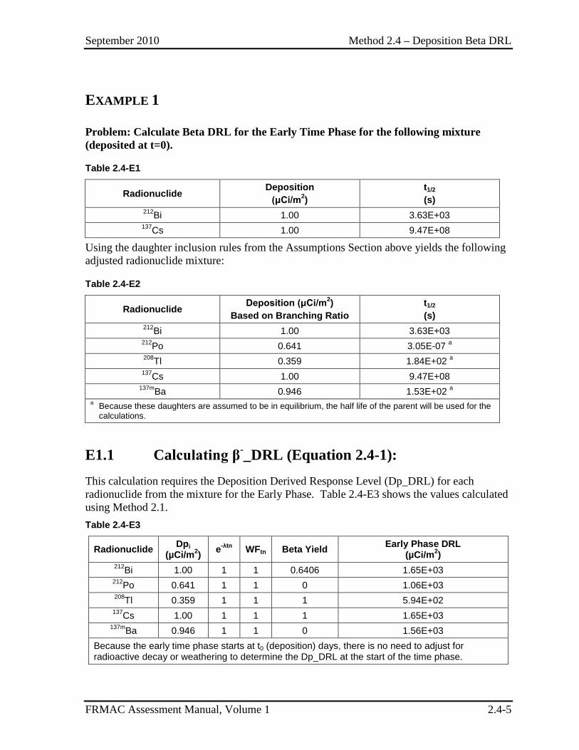
September 2010 Method 2.4 – Deposition Beta DRL
FRMAC Assessment Manual, Volume 1 2.4-5
EXAMPLE 1
Problem: Calculate Beta DRL for the Early Time Phase for the following mixture (deposited at t=0).
Table 2.4-E1
Radionuclide Deposition (μCi/m2)
t1/2
(s) 212Bi 1.00 3.63E+03 137Cs 1.00 9.47E+08
Using the daughter inclusion rules from the Assumptions Section above yields the following adjusted radionuclide mixture:
Table 2.4-E2
Radionuclide Deposition (μCi/m2) Based on Branching Ratio
t1/2
(s) 212Bi 1.00 3.63E+03 212Po 0.641 3.05E-07 a 208Tl 0.359 1.84E+02 a
137Cs 1.00 9.47E+08 137mBa 0.946 1.53E+02 a
a Because these daughters are assumed to be in equilibrium, the half life of the parent will be used for the calculations.
E1.1 Calculating β-_DRL (Equation 2.4-1): This calculation requires the Deposition Derived Response Level (Dp_DRL) for each radionuclide from the mixture for the Early Phase. Table 2.4-E3 shows the values calculated using Method 2.1. Table 2.4-E3
Radionuclide Dpi (µCi/m2) e-λtn WFtn Beta Yield Early Phase DRL
(µCi/m2) 212Bi 1.00 1 1 0.6406 1.65E+03 212Po 0.641 1 1 0 1.06E+03 208Tl 0.359 1 1 1 5.94E+02
137Cs 1.00 1 1 1 1.65E+03 137mBa 0.946 1 1 0 1.56E+03
Because the early time phase starts at t0 (deposition) days, there is no need to adjust for radioactive decay or weathering to determine the Dp_DRL at the start of the time phase.
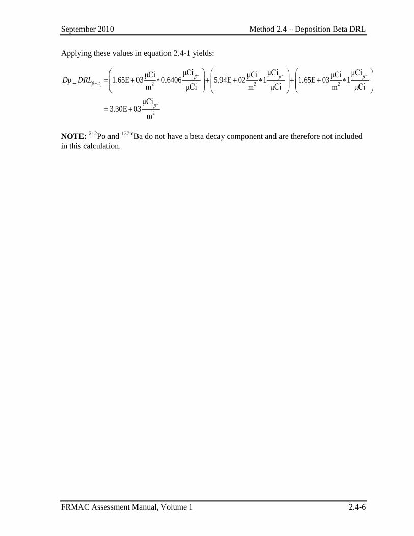
September 2010 Method 2.4 – Deposition Beta DRL
FRMAC Assessment Manual, Volume 1 2.4-6
Applying these values in equation 2.4-1 yields:
0, 2 2 2
2
μCi μCi μCiμCi μCi μCi_ 1.65E 03 0.6406 5.94E 02 1 1.65E 03 1m μCi m μCi m μCi
μCi3.30E 03
m
β β ββ
β
− − −
−
−
= + ∗ + + ∗ + + ∗
= +
tDp DRL
NOTE: 212Po and 137mBa do not have a beta decay component and are therefore not included in this calculation.
September 2010 Method 2.5 – Deposition Projected Public Dose
FRMAC Assessment Manual, Volume 1 2.5-1
METHOD 2.5 DEPOSITION PROJECTED PUBLIC DOSE
Application This method has been developed to calculate the Deposition Projected Public Dose (Dp_PPD), the dose received by members of the public, from a deposition of radioactive material. The Dp_PPD may be calculated from a measured areal activity, Deposition PPD (Dp_PPDDp) or external dose rate, Deposition Dose Rate PPD (Dp_PPDDR).
The Dp_PPD:
• Uses a measured areal activity of a marker radionuclide or a measured dose rate to calculate the dose that a receptor is projected to receive over a specified time phase due to the external dose from material deposited on the ground (i.e., groundshine) and the dose from the inhalation of resuspended material.
• Is compared to Protective Action Guides (PAGs) for radiological emergency planning established by the Environmental Protection Agency (EPA) (EPA92) or the Department of Homeland Security (DHS) (DHS08).
• Is used to create data products and define dose levels to assist decision makers in determining where it may be advisable to implement protective actions (e.g., sheltering, evacuation, relocation).
• Is calculated from the Deposition Derived Response Level (Dp_DRLDp) value calculated in Method 2.1 or the Deposition Dose Rate Derived Response Level (Dp_DRLDR) value calculated in Method 2.2.
Discussion The Dp_PPD is a value obtained by:
• Multiplying the local deposition (areal activity) of a radionuclide at the start of the time phase by the Total Dose Parameter for Deposition for that radionuclide and time phase and summing that product over all the radionuclides in the mixture, or
• Comparing a measured dose rate (mrem/hr) to the calculated Dp_DRLDR for a mixture. Because the Dp_DRLDR is determined using a regulatory PAG, the ratio of the measured value to the appropriate DRL can be used to calculate a projected dose relative to the PAG.
September 2010 Method 2.5 – Deposition Projected Public Dose
FRMAC Assessment Manual, Volume 1 2.5-2
Assumptions There are no additional assumptions beyond the default assumptions.
Inputs In addition to the default inputs, the following information is required to perform the calculations described in this method:
• Total Dose Parameter for Deposition (TDP_Dp) for each radionuclide and Mixture Total Dose Parameter for Deposition (MTDP_Dp) for the mixture – Calculated using Method 2.1.
• Deposition Dose Rate Derived Response Level (Dp_DRLDR) for the mixture – Calculated using Method 2.2.
• Mixture External Dose Factor for Deposition (MExDF_Dp) for the mixture – Calculated using Method 2.2.
If incident-specific values have not been established, recommended default values for selected inputs are available in Appendix C.
Outputs The final output of this method is the Projected Public Dose for a deposition of radioactive material (Dp_PPD).
Final
Dp_PPDDp = Deposition Projected Public Dose over the time phase under consideration, mrem
Dp_PPDDR = Deposition Dose Rate Projected Public Dose over the time phase under consideration, mrem
Intermediate
The following intermediate values may be referenced in other methods and are called out here for clarity.
None
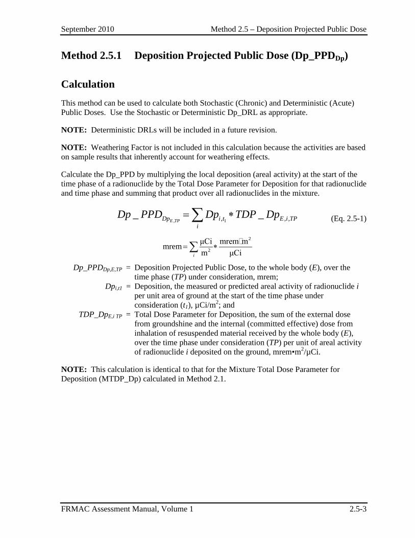
September 2010 Method 2.5 – Deposition Projected Public Dose
FRMAC Assessment Manual, Volume 1 2.5-3
Method 2.5.1 Deposition Projected Public Dose (Dp_PPDDp)
Calculation This method can be used to calculate both Stochastic (Chronic) and Deterministic (Acute) Public Doses. Use the Stochastic or Deterministic Dp_DRL as appropriate.
NOTE: Deterministic DRLs will be included in a future revision.
NOTE: Weathering Factor is not included in this calculation because the activities are based on sample results that inherently account for weathering effects.
Calculate the Dp_PPD by multiplying the local deposition (areal activity) at the start of the time phase of a radionuclide by the Total Dose Parameter for Deposition for that radionuclide and time phase and summing that product over all radionuclides in the mixture.
, 1, , ,_ _E TPDp i t E i TP
iDp PPD Dp TDP Dp= ∗∑ (Eq. 2.5-1)
2
2
μCi mrem mmremm μCii
= ∗∑
Dp_PPDDp,E,TP = Deposition Projected Public Dose, to the whole body (E), over the time phase (TP) under consideration, mrem;
Dpi,t1 = Deposition, the measured or predicted areal activity of radionuclide i per unit area of ground at the start of the time phase under consideration (t1), µCi/m2; and
TDP_DpE,i TP = Total Dose Parameter for Deposition, the sum of the external dose from groundshine and the internal (committed effective) dose from inhalation of resuspended material received by the whole body (E), over the time phase under consideration (TP) per unit of areal activity of radionuclide i deposited on the ground, mrem•m2/µCi.
NOTE: This calculation is identical to that for the Mixture Total Dose Parameter for Deposition (MTDP_Dp) calculated in Method 2.1.
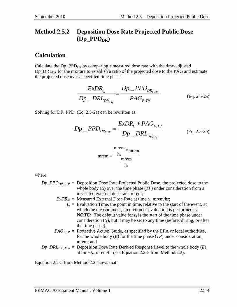
September 2010 Method 2.5 – Deposition Projected Public Dose
FRMAC Assessment Manual, Volume 1 2.5-4
Method 2.5.2 Deposition Dose Rate Projected Public Dose (Dp_PPDDR)
Calculation Calculate the Dp_PPDDR by comparing a measured dose rate with the time-adjusted Dp_DRLDR for the mixture to establish a ratio of the projected dose to the PAG and estimate the projected dose over a specified time phase.
,
, ,
__
E TPn
E tn
DRt
DR E TP
Dp PPDExDRDp DRL PAG
= (Eq. 2.5-2a)
Solving for DR_PPD, (Eq. 2.5-2a) can be rewritten as:
,
,
,__
n
E TP
E tn
t E TPDR
DR
ExDR PAGDp PPD
Dp DRL∗
= (Eq. 2.5-2b)
mrem *mremhrmrem mrem
hr
=
where:
Dp_PPDDR,E,TP = Deposition Dose Rate Projected Public Dose, the projected dose to the whole body (E) over the time phase (TP) under consideration from a measured external dose rate, mrem;
ExDRtn = Measured External Dose Rate at time tn, mrem/hr; tn = Evaluation Time, the point in time, relative to the start of the event, at
which the measurement, prediction or evaluation is performed, s; NOTE: The default value for tn is the start of the time phase under
consideration (t1), but it may be set to any time (before, during, or after the time phase).
PAGE,TP = Protective Action Guide, as specified by the EPA or local authorities, for the whole body (E) for the time phase (TP) under consideration, mrem; and
Dp_DRLDR , E,tn = Deposition Dose Rate Derived Response Level to the whole body (E) at time tn, mrem/hr (see Equation 2.2-5 from Method 2.2).
Equation 2.2-5 from Method 2.2 shows that:
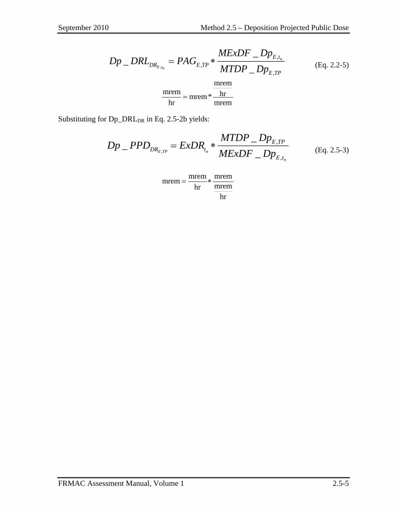
September 2010 Method 2.5 – Deposition Projected Public Dose
FRMAC Assessment Manual, Volume 1 2.5-5
,
,,
,
__
_n
E tn
E tDR E TP
E TP
MExDF DpDp DRL PAG
MTDP Dp= ∗ (Eq. 2.2-5)
mremmrem hrmrem*
hr mrem=
Substituting for Dp_DRLDR in Eq. 2.5-2b yields:
,
,
,
__
_E TP n
n
E TPDR t
E t
MTDP DpDp PPD ExDR
MExDF Dp= ∗ (Eq. 2.5-3)
mrem mremmrem mremhrhr
= ∗
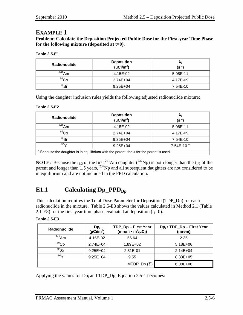
September 2010 Method 2.5 – Deposition Projected Public Dose
FRMAC Assessment Manual, Volume 1 2.5-6
EXAMPLE 1 Problem: Calculate the Deposition Projected Public Dose for the First-year Time Phase for the following mixture (deposited at t=0).
Table 2.5-E1
Radionuclide Deposition (µCi/m2)
λi
(s-1) 241Am 4.15E-02 5.08E-11 60Co 2.74E+04 4.17E-09 90Sr 9.25E+04 7.54E-10
Using the daughter inclusion rules yields the following adjusted radionuclide mixture:
Table 2.5-E2
Radionuclide Deposition (µCi/m2)
λi
(s-1) 241Am 4.15E-02 5.08E-11 60Co 2.74E+04 4.17E-09 90Sr 9.25E+04 7.54E-10 90Y 9.25E+04 7.54E-10 a
a Because the daughter is in equilibrium with the parent, the λ for the parent is used.
NOTE: Because the t1/2 of the first 241Am daughter (237Np) is both longer than the t1/2 of the parent and longer than 1.5 years, 237Np and all subsequent daughters are not considered to be in equilibrium and are not included in the PPD calculation.
E1.1 Calculating Dp_PPDDp This calculation requires the Total Dose Parameter for Deposition (TDP_Dp) for each radionuclide in the mixture. Table 2.5-E3 shows the values calculated in Method 2.1 (Table 2.1-E8) for the first-year time phase evaluated at deposition (t1=0). Table 2.5-E3
Radionuclide Dpi (µCi/m2)
TDP_Dp – First Year (mrem • m2/µCi)
Dpi • TDP_Dp – First Year (mrem)
241Am 4.15E-02 56.64 2.35 60Co 2.74E+04 1.89E+02 5.18E+06 90Sr 9.25E+04 2.31E-01 2.14E+04 90Y 9.25E+04 9.55 8.83E+05
MTDP_Dp (∑) 6.08E+06
Applying the values for Dpi and TDP_Dp, Equation 2.5-1 becomes:
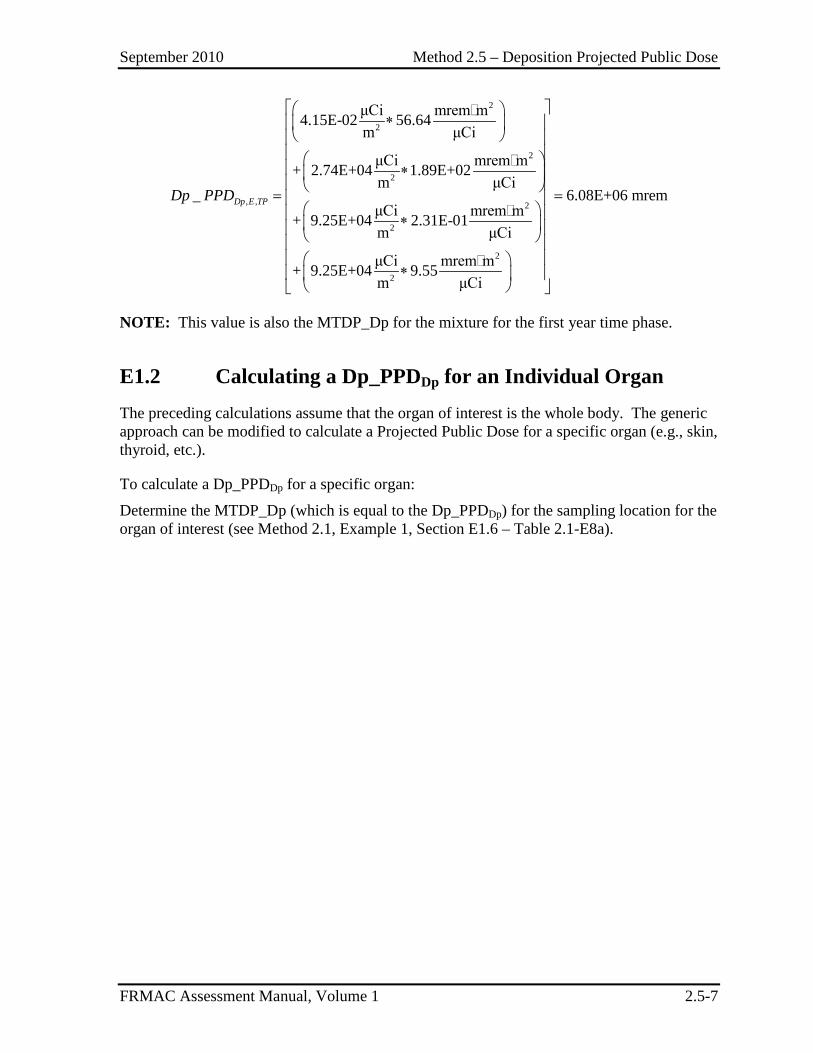
September 2010 Method 2.5 – Deposition Projected Public Dose
FRMAC Assessment Manual, Volume 1 2.5-7
2
2
2
2
, , 2
2
2
2
μCi mrem m4.15E-02 56.64m μCi
μCi mrem m+ 2.74E+04 1.89E+02m μCi
_ 6.08E+06 mrμCi mrem m+ 9.25E+04 2.31E-01m μCi
μCi mrem m+ 9.25E+04 9.55m μCi
Dp E TPDp PPD
∗
∗ = =
∗
∗
em
NOTE: This value is also the MTDP_Dp for the mixture for the first year time phase.
E1.2 Calculating a Dp_PPDDp for an Individual Organ The preceding calculations assume that the organ of interest is the whole body. The generic approach can be modified to calculate a Projected Public Dose for a specific organ (e.g., skin, thyroid, etc.).
To calculate a Dp_PPDDp for a specific organ:
Determine the MTDP_Dp (which is equal to the Dp_PPDDp) for the sampling location for the organ of interest (see Method 2.1, Example 1, Section E1.6 – Table 2.1-E8a).

September 2010 Method 2.5 – Deposition Projected Public Dose
FRMAC Assessment Manual, Volume 1 2.5-8
EXAMPLE 2
Problem: Calculate the Deposition Dose Rate Projected Public Dose for the First-year Time Phase for the following mixture (deposited at t=0).
Assume the dose rate measurement was performed on Day 100 (tn=100 days). Table 2.5-E1 (repeated)
Radionuclide Deposition (µCi/m2)
λi
(s-1) 241Am 4.15E-02 5.08E-11 60Co 2.74E+04 4.17E-09 90Sr 9.25E+04 7.54E-10
Using the daughter inclusion rules yields the following adjusted radionuclide mixture:
Table 2.5-E2 (repeated)
Radionuclide Deposition (µCi/m2) λi (s-1) 241Am 4.15E-02 5.08E-11 60Co 2.74E+04 4.17E-09 90Sr 9.25E+04 7.54E-10 90Y 9.25E+04 7.54E-10 a
a Because the daughter is in equilibrium with the parent, the λ for the parent is used.
NOTE: Because the t1/2 of the first 241Am daughter (237Np) is both longer than the t1/2 of the parent and longer than 1.5 years, 237Np and all subsequent daughters are not considered to be in equilibrium and are not included in the PPDS calculation.
E2.1 Calculating MExDF_Dptn This calculation requires the External Dose Factors (ExDF) for each radionuclide in the mixture and a time within the time phase at which the measurement (ExDRtn) was taken.
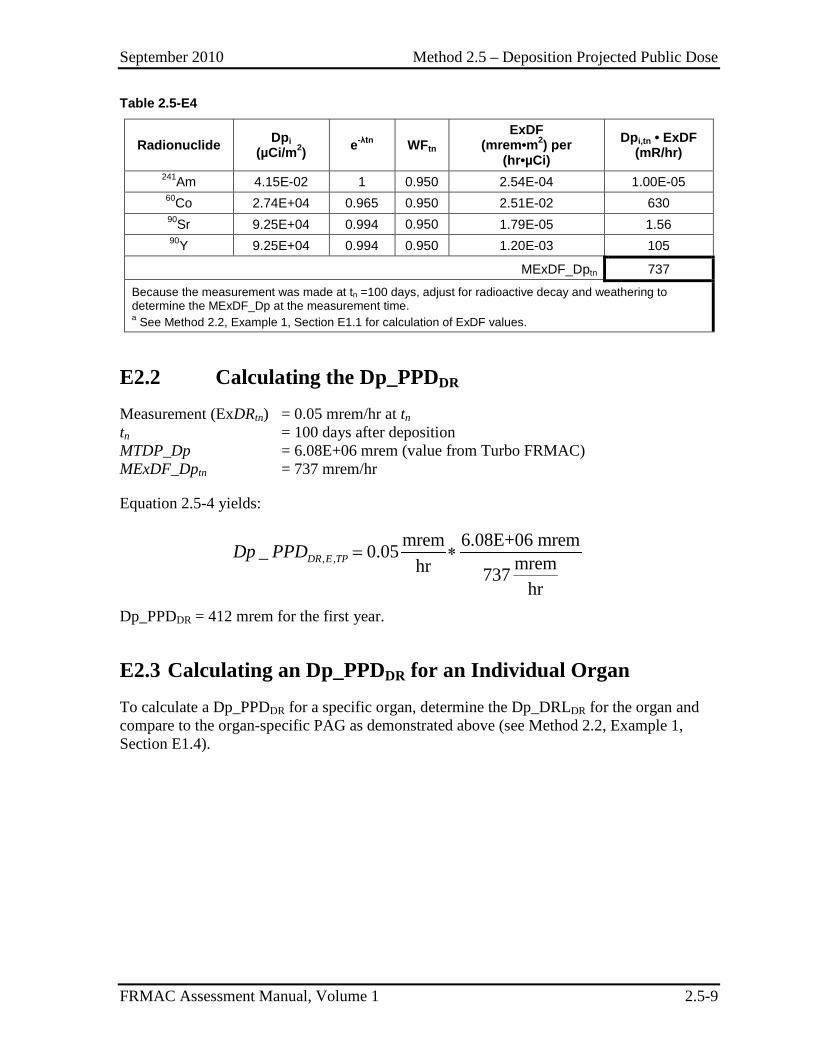
September 2010 Method 2.5 – Deposition Projected Public Dose
FRMAC Assessment Manual, Volume 1 2.5-9
Table 2.5-E4
Radionuclide Dpi (µCi/m2) e-λtn WFtn
ExDF (mrem•m2) per
(hr•µCi) Dpi,tn • ExDF
(mR/hr) 241Am 4.15E-02 1 0.950 2.54E-04 1.00E-05 60Co 2.74E+04 0.965 0.950 2.51E-02 630 90Sr 9.25E+04 0.994 0.950 1.79E-05 1.56 90Y 9.25E+04 0.994 0.950 1.20E-03 105
MExDF_Dptn 737
Because the measurement was made at tn =100 days, adjust for radioactive decay and weathering to determine the MExDF_Dp at the measurement time. a See Method 2.2, Example 1, Section E1.1 for calculation of ExDF values.
E2.2 Calculating the Dp_PPDDR Measurement (ExDRtn) = 0.05 mrem/hr at tn tn = 100 days after deposition MTDP_Dp = 6.08E+06 mrem (value from Turbo FRMAC) MExDF_Dptn = 737 mrem/hr
Equation 2.5-4 yields:
, ,mrem 6.08E+06 mrem_ 0.05 mremhr 737
hr
DR E TPDp PPD = ∗
Dp_PPDDR = 412 mrem for the first year.
E2.3 Calculating an Dp_PPDDR for an Individual Organ To calculate a Dp_PPDDR for a specific organ, determine the Dp_DRLDR for the organ and compare to the organ-specific PAG as demonstrated above (see Method 2.2, Example 1, Section E1.4).

September 2010 Method 2.5 – Deposition Projected Public Dose
FRMAC Assessment Manual, Volume 1 2.5-10
This page intentionally left blank.
September 2010 Method 2.6 – Skin Dose
FRMAC Assessment Manual, Volume 1 2.6-1
METHOD 2.6 SKIN DOSE
This method is reserved for future development.

September 2010 Method 2.6 – Skin Dose
FRMAC Assessment Manual, Volume 1 2.6-2
This page intentionally left blank.
September 2010 Method 2.7 – Determining Return Times
FRMAC Assessment Manual, Volume 1 2.7-1
METHOD 2.7 DETERMINING RETURN TIMES
This method is reserved for future development.

September 2010 Method 2.7 – Determining Return Times
FRMAC Assessment Manual, Volume 1 2.7-2
This page intentionally left blank.
September 2010 Method 2.8 – Assessing Nuclear Detonations
FRMAC Assessment Manual, Volume 1 2.8-1
METHOD 2.8 ASSESSING NUCLEAR DETONATIONS
Application This method has been developed to calculate Doses, Stay Times, and Improvised Nuclear Device Derived Response Levels for a deposition of radioactive fallout after a nuclear detonation.
The IND_DRLDR
• Represents the dose rate (mrem/hr, measured at 1 m above the ground) at a given time (tn), from all radionuclides in the fallout mixture that will be expected to produce a dose equal to the appropriate Protective Action Guide (PAG) over the time phase under consideration.
• Is derived from the PAGs for radiological emergency planning established by the Environmental Protection Agency (EPA) (EPA92) or the Department of Homeland Security (DHS) (DHS08). A projected or measured dose rate value greater than the IND_DRLDR indicates that the PAG has the potential to be exceeded.
• Is used to create data products and define dose rates to assist decision makers in determining where implementing protective actions (e.g., sheltering, evacuation, relocation) may be advisable.
Discussion The IND_DRLDR relates a measured dose rate to the external dose from material deposited on the ground (i.e., groundshine). The inhalation dose from nuclear weapon fallout is insignificant over the time phase where this method will be applied, and therefore this method only considers external dose.
The IND_DRLDR is based on the dose rate of the entire fallout mixture, not on concentrations of individual radionuclides.
In cases of nuclear detonation, external radiation levels decrease rapidly. Due to the “front weighting” of doses, strong consideration should be given to setting the time phase to start as early as possible (however, see Assumption 2) even if protective actions are not able to be implemented until later. This should produce a more accurate total dose projection to the affected population.
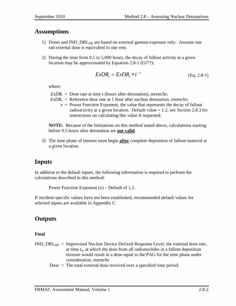
September 2010 Method 2.8 – Assessing Nuclear Detonations
FRMAC Assessment Manual, Volume 1 2.8-2
Assumptions 1) Doses and IND_DRLDR are based on external gamma exposure only. Assume one
rad external dose is equivalent to one rem.
2) During the time from 0.5 to 5,000 hours, the decay of fallout activity at a given location may be approximated by Equation 2.8-1 (Gl77):
−= ∗ xt rExDR ExDR t (Eq. 2.8-1)
where:
ExDRt = Dose rate at time t (hours after detonation), mrem/hr; ExDRr = Reference dose rate at 1 hour after nuclear detonation, mrem/hr; x = Power Function Exponent, the value that represents the decay of fallout
radioactivity at a given location. Default value = 1.2, see Section 2.8.3 for instructions on calculating this value if requested.
NOTE: Because of the limitations on this method stated above, calculations starting before 0.5 hours after detonation are not valid.
3) The time phase of interest must begin after complete deposition of fallout material at a given location.
Inputs In addition to the default inputs, the following information is required to perform the calculations described in this method:
Power Function Exponent (x) – Default of 1.2.
If incident-specific values have not been established, recommended default values for selected inputs are available in Appendix C.
Outputs
Final
IND_DRLDR = Improvised Nuclear Device Derived Response Level, the external dose rate, at time tn, at which the dose from all radionuclides in a fallout deposition mixture would result in a dose equal to the PAG for the time phase under consideration, mrem/hr
Dose = The total external dose received over a specified time period.
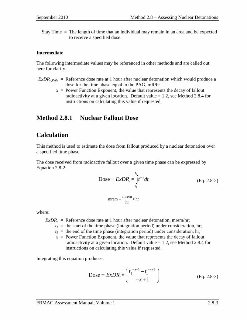
September 2010 Method 2.8 – Assessing Nuclear Detonations
FRMAC Assessment Manual, Volume 1 2.8-3
Stay Time = The length of time that an individual may remain in an area and be expected to receive a specified dose.
Intermediate
The following intermediate values may be referenced in other methods and are called out here for clarity.
ExDRr,PAG = Reference dose rate at 1 hour after nuclear detonation which would produce a dose for the time phase equal to the PAG, mR/hr
x = Power Function Exponent, the value that represents the decay of fallout radioactivity at a given location. Default value = 1.2, see Method 2.8.4 for instructions on calculating this value if requested.
Method 2.8.1 Nuclear Fallout Dose
Calculation This method is used to estimate the dose from fallout produced by a nuclear detonation over a specified time phase.
The dose received from radioactive fallout over a given time phase can be expressed by Equation 2.8-2:
2
1
Dose −= ∗ ∫t
xr
t
ExDR t dt (Eq. 2.8-2)
mremmrem hrhr
= ∗
where:
ExDRr = Reference dose rate at 1 hour after nuclear detonation, mrem/hr; t1 = the start of the time phase (integration period) under consideration, hr; t2 = the end of the time phase (integration period) under consideration, hr; x = Power Function Exponent, the value that represents the decay of fallout
radioactivity at a given location. Default value = 1.2, see Method 2.8.4 for instructions on calculating this value if requested.
Integrating this equation produces:
1 1
2 1Dose1
− + − + −= ∗ − +
x x
rt tExDR
x (Eq. 2.8-3)
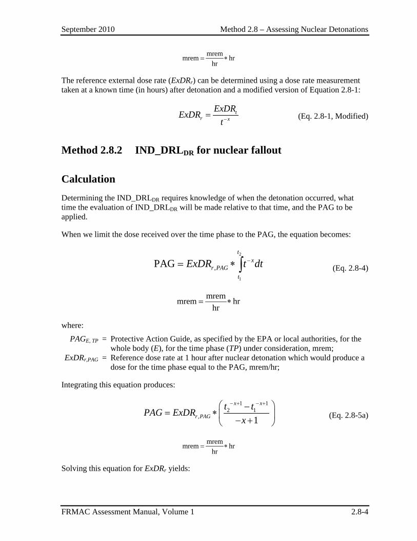
September 2010 Method 2.8 – Assessing Nuclear Detonations
FRMAC Assessment Manual, Volume 1 2.8-4
mremmrem hr
hr= ∗
The reference external dose rate (ExDRr) can be determined using a dose rate measurement taken at a known time (in hours) after detonation and a modified version of Equation 2.8-1:
−= tr x
ExDRExDRt (Eq. 2.8-1, Modified)
Method 2.8.2 IND_DRLDR for nuclear fallout
Calculation Determining the IND_DRLDR requires knowledge of when the detonation occurred, what time the evaluation of IND_DRLDR will be made relative to that time, and the PAG to be applied.
When we limit the dose received over the time phase to the PAG, the equation becomes:
2
1
,PAG −= ∗ ∫t
xr PAG
t
ExDR t dt (Eq. 2.8-4)
mremmrem hr
hr= ∗
where:
PAGE, TP = Protective Action Guide, as specified by the EPA or local authorities, for the whole body (E), for the time phase (TP) under consideration, mrem;
ExDRr,PAG = Reference dose rate at 1 hour after nuclear detonation which would produce a dose for the time phase equal to the PAG, mrem/hr;
Integrating this equation produces:
1 1
2 1, 1
− + − + −= ∗ − +
x x
r PAGt tPAG ExDR
x (Eq. 2.8-5a)
mremmrem hr
hr= ∗
Solving this equation for ExDRr yields:
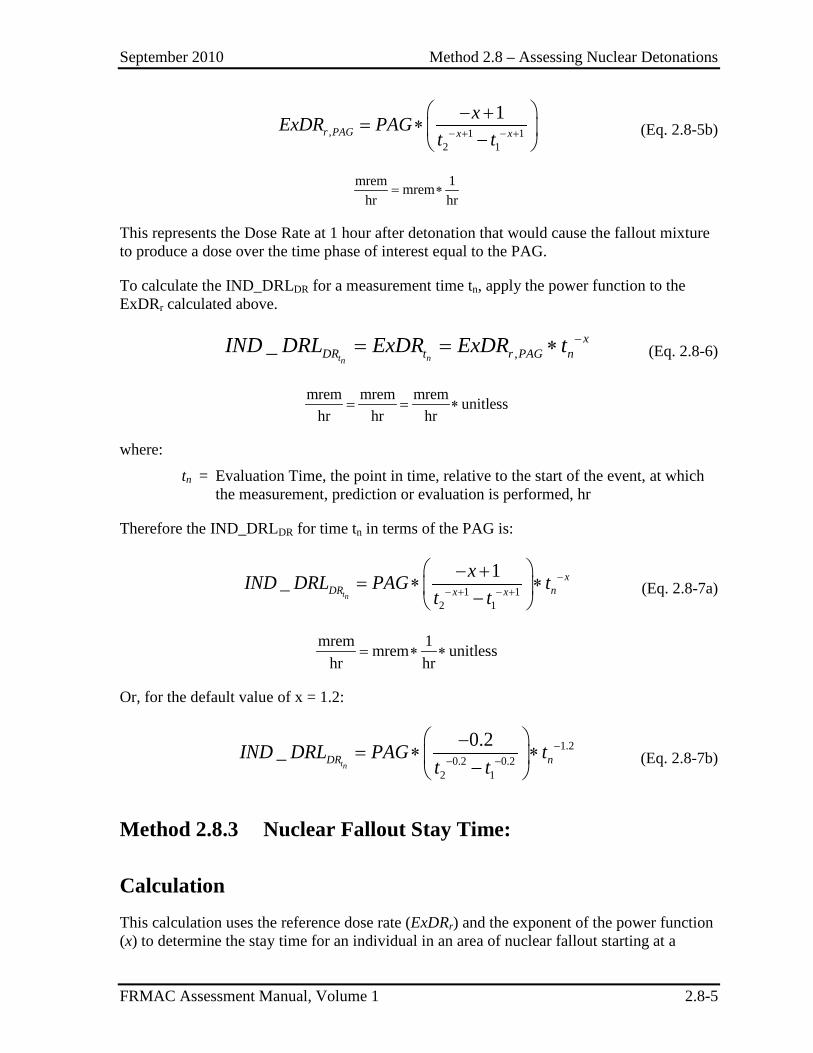
September 2010 Method 2.8 – Assessing Nuclear Detonations
FRMAC Assessment Manual, Volume 1 2.8-5
, 1 12 1
1− + − +
− += ∗ −
r PAG x x
xExDR PAGt t (Eq. 2.8-5b)
mrem 1mrem
hr hr= ∗
This represents the Dose Rate at 1 hour after detonation that would cause the fallout mixture to produce a dose over the time phase of interest equal to the PAG.
To calculate the IND_DRLDR for a measurement time tn, apply the power function to the ExDRr calculated above.
,_t nn
xDR t r PAG nIND DRL ExDR ExDR t −= = ∗ (Eq. 2.8-6)
mrem mrem mrem unitlesshr hr hr
= = ∗
where:
tn = Evaluation Time, the point in time, relative to the start of the event, at which the measurement, prediction or evaluation is performed, hr
Therefore the IND_DRLDR for time tn in terms of the PAG is:
1 12 1
1_tn
xDR nx x
xIND DRL PAG tt t
−− + − +
− += ∗ ∗ −
(Eq. 2.8-7a)
mrem 1mrem unitless
hr hr= ∗ ∗
Or, for the default value of x = 1.2:
1.2
0.2 0.22 1
0.2_tnDR nIND DRL PAG t
t t−
− −
−= ∗ ∗ −
(Eq. 2.8-7b)
Method 2.8.3 Nuclear Fallout Stay Time:
Calculation This calculation uses the reference dose rate (ExDRr) and the exponent of the power function (x) to determine the stay time for an individual in an area of nuclear fallout starting at a
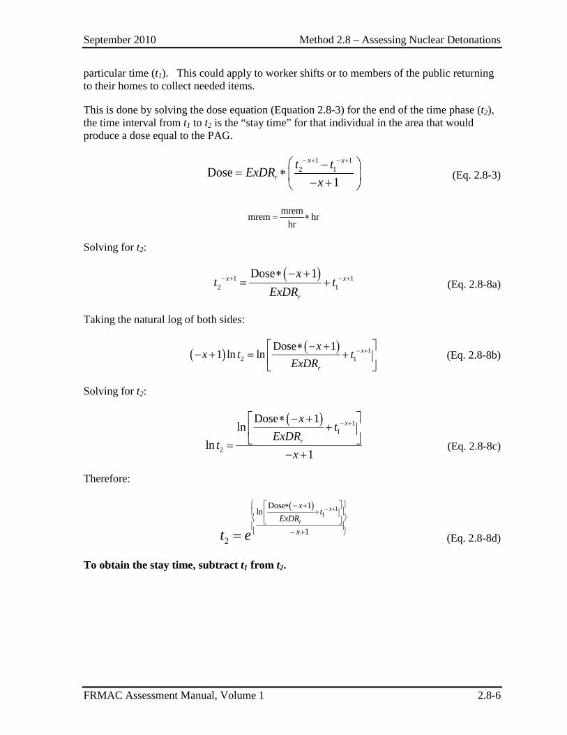
September 2010 Method 2.8 – Assessing Nuclear Detonations
FRMAC Assessment Manual, Volume 1 2.8-6
particular time (t1). This could apply to worker shifts or to members of the public returning to their homes to collect needed items.
This is done by solving the dose equation (Equation 2.8-3) for the end of the time phase (t2), the time interval from t1 to t2 is the “stay time” for that individual in the area that would produce a dose equal to the PAG.
1 12 1Dose
1
− + − + −= ∗ − +
x x
rt tExDR
x (Eq. 2.8-3)
mremmrem hr
hr= ∗
Solving for t2:
( )1 12 1
Dose 1− + − +∗ − += +x x
r
xt t
ExDR (Eq. 2.8-8a)
Taking the natural log of both sides:
( ) ( ) 1
2 1
Dose 11 ln ln − +∗ − +
− + = +
x
r
xx t t
ExDR (Eq. 2.8-8b)
Solving for t2:
( ) 11
2
Dose 1ln
ln1
− +∗ − + +
=− +
x
r
xt
ExDRt
x (Eq. 2.8-8c)
Therefore:
( ) 11
Dose 1ln
12
− + ∗ − + +
− + =
x
r
xt
ExDRxt e (Eq. 2.8-8d)
To obtain the stay time, subtract t1 from t2.
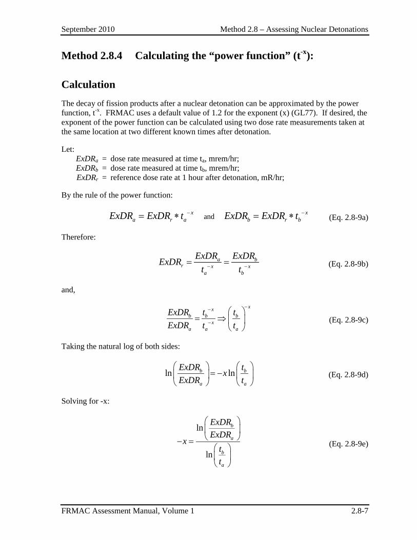
September 2010 Method 2.8 – Assessing Nuclear Detonations
FRMAC Assessment Manual, Volume 1 2.8-7
Method 2.8.4 Calculating the “power function” (t-x):
Calculation The decay of fission products after a nuclear detonation can be approximated by the power function, t-x. FRMAC uses a default value of 1.2 for the exponent (x) (GL77). If desired, the exponent of the power function can be calculated using two dose rate measurements taken at the same location at two different known times after detonation.
Let: ExDRa = dose rate measured at time ta, mrem/hr; ExDRb = dose rate measured at time tb, mrem/hr; ExDRr = reference dose rate at 1 hour after detonation, mR/hr;
By the rule of the power function:
and− −= ∗ = ∗x xa r a b r bExDR ExDR t ExDR ExDR t (Eq. 2.8-9a)
Therefore:
− −= =a br x x
a b
ExDR ExDRExDRt t (Eq. 2.8-9b)
and,
−−
−
= ⇒
xxb b b
xa a a
ExDR t tExDR t t (Eq. 2.8-9c)
Taking the natural log of both sides:
ln ln
= −
b b
a a
ExDR txExDR t (Eq. 2.8-9d)
Solving for -x:
ln
ln
− =
b
a
b
a
ExDRExDR
xtt
(Eq. 2.8-9e)
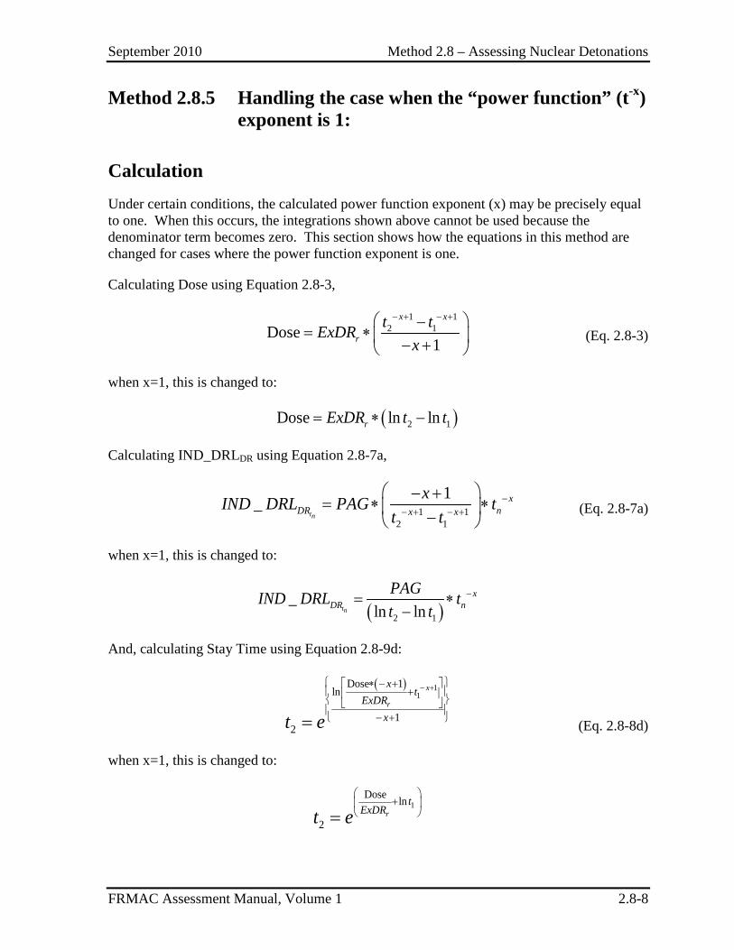
September 2010 Method 2.8 – Assessing Nuclear Detonations
FRMAC Assessment Manual, Volume 1 2.8-8
Method 2.8.5 Handling the case when the “power function” (t-x) exponent is 1:
Calculation Under certain conditions, the calculated power function exponent (x) may be precisely equal to one. When this occurs, the integrations shown above cannot be used because the denominator term becomes zero. This section shows how the equations in this method are changed for cases where the power function exponent is one.
Calculating Dose using Equation 2.8-3,
1 1
2 1Dose1
− + − + −= ∗ − +
x x
rt tExDR
x (Eq. 2.8-3)
when x=1, this is changed to:
( )2 1Dose ln ln= ∗ −rExDR t t
Calculating IND_DRLDR using Equation 2.8-7a,
1 12 1
1_tn
xDR nx x
xIND DRL PAG tt t
−− + − +
− += ∗ ∗ −
(Eq. 2.8-7a)
when x=1, this is changed to:
( )2 1
_ln lntn
xDR n
PAGIND DRL tt t
−= ∗−
And, calculating Stay Time using Equation 2.8-9d:
( ) 11
Dose 1ln
12
− + ∗ − + +
− + =
x
r
xt
ExDRxt e (Eq. 2.8-8d)
when x=1, this is changed to:
1
Dose ln
2
+
= rt
ExDRt e
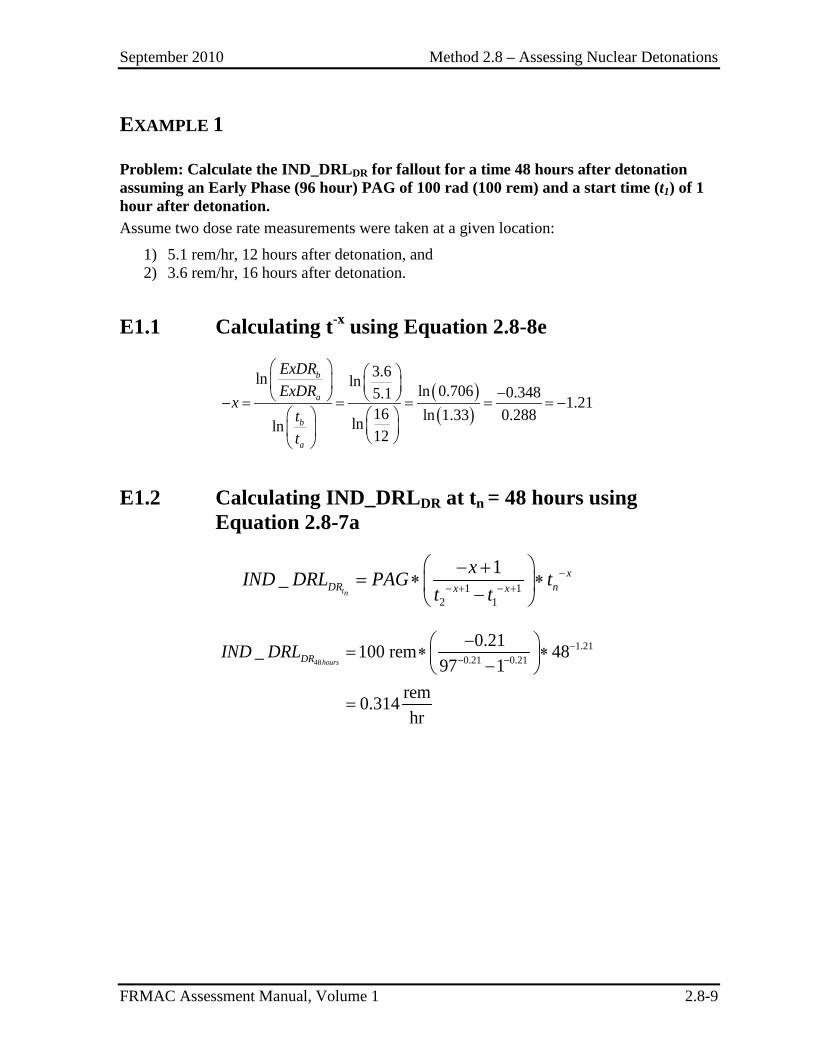
September 2010 Method 2.8 – Assessing Nuclear Detonations
FRMAC Assessment Manual, Volume 1 2.8-9
EXAMPLE 1
Problem: Calculate the IND_DRLDR for fallout for a time 48 hours after detonation assuming an Early Phase (96 hour) PAG of 100 rad (100 rem) and a start time (t1) of 1 hour after detonation. Assume two dose rate measurements were taken at a given location:
1) 5.1 rem/hr, 12 hours after detonation, and 2) 3.6 rem/hr, 16 hours after detonation.
E1.1 Calculating t-x using Equation 2.8-8e
( )( )
3.6ln ln ln 0.706 0.3485.1 1.2116 ln 1.33 0.288lnln 12
− − = = = = = −
b
a
b
a
ExDRExDR
xtt
E1.2 Calculating IND_DRLDR at tn = 48 hours using Equation 2.8-7a
1 1
2 1
1_tn
xDR nx x
xIND DRL PAG tt t
−− + − +
− += ∗ ∗ −
48
1.210.21 0.21
0.21_ 100 rem 4897 1
rem0.314hr
hoursDRIND DRL −− −
− = ∗ ∗ −
=
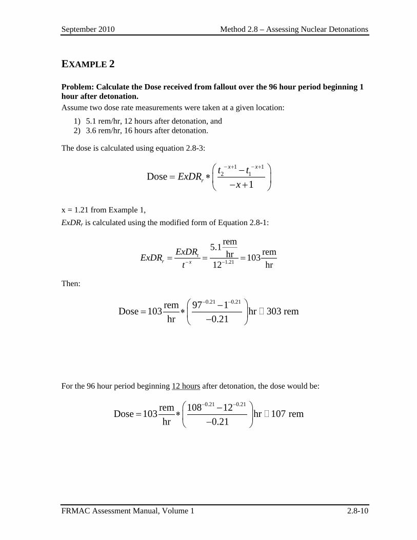
September 2010 Method 2.8 – Assessing Nuclear Detonations
FRMAC Assessment Manual, Volume 1 2.8-10
EXAMPLE 2
Problem: Calculate the Dose received from fallout over the 96 hour period beginning 1 hour after detonation. Assume two dose rate measurements were taken at a given location:
1) 5.1 rem/hr, 12 hours after detonation, and 2) 3.6 rem/hr, 16 hours after detonation.
The dose is calculated using equation 2.8-3:
1 12 1Dose
1
− + − + −= ∗ − +
x x
rt tExDR
x
x = 1.21 from Example 1, ExDRr is calculated using the modified form of Equation 2.8-1:
1.21
rem5.1 remhr 10312 hr− −= = =t
r x
ExDRExDRt
Then:
0.21 0.21rem 97 1Dose 103 hr 303 remhr 0.21
− − −= ∗ −
For the 96 hour period beginning 12 hours after detonation, the dose would be:
0.21 0.21rem 108 12Dose 103 hr 107 remhr 0.21
− − −= ∗ −
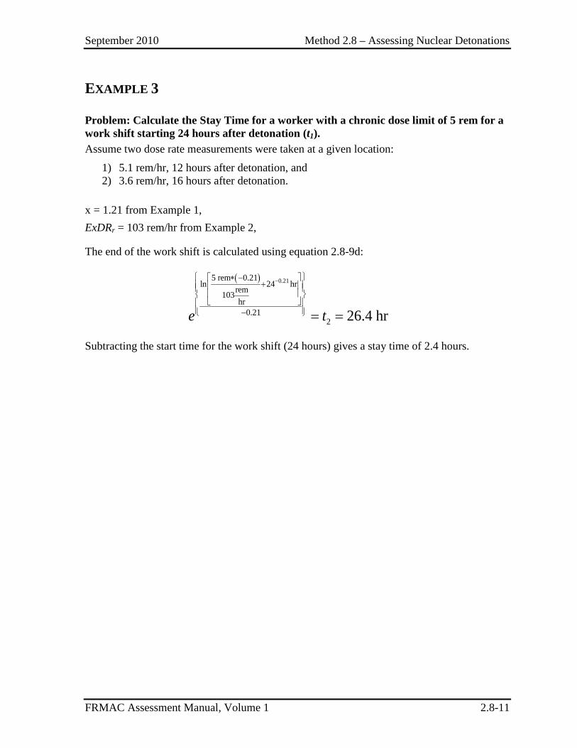
September 2010 Method 2.8 – Assessing Nuclear Detonations
FRMAC Assessment Manual, Volume 1 2.8-11
EXAMPLE 3
Problem: Calculate the Stay Time for a worker with a chronic dose limit of 5 rem for a work shift starting 24 hours after detonation (t1). Assume two dose rate measurements were taken at a given location:
1) 5.1 rem/hr, 12 hours after detonation, and 2) 3.6 rem/hr, 16 hours after detonation.
x = 1.21 from Example 1, ExDRr = 103 rem/hr from Example 2,
The end of the work shift is calculated using equation 2.8-9d:
( ) 0.215 rem 0.21ln 24 hrrem103
hr0.21
2 26.4 hr
− ∗ − +
− = =e t
Subtracting the start time for the work shift (24 hours) gives a stay time of 2.4 hours.
September 2010 Method 2.8 – Assessing Nuclear Detonations
FRMAC Assessment Manual, Volume 1 2.8-12
This page intentionally left blank.
September 2010 Section 3 – Worker Protection Methods
FRMAC Assessment Manual, Volume 1 3.0-1
SECTION 3. WORKER PROTECTION METHODS
Effective Date
Introduction .............................................................................................. 3.0-3 9/2010
Method 3.1 Basic Worker Protection ....................................................... 3.1-1 9/2010
Method 3.2 Advanced Worker Protection Total Dose Calculation .......... 3.2-1 9/2010
Method 3.3 Advanced Worker Protection Stay Time Calculation ........... 3.3-1 Reserved
Method 3.4 Worker Skin Dose ................................................................. 3.4-1 Reserved

September 2010 Section 3 – Worker Protection Methods
FRMAC Assessment Manual, Volume 1 3.0-2
This page intentionally left blank.
September 2010 Section 3 – Worker Protection Methods
FRMAC Assessment Manual, Volume 1 3.0-3
INTRODUCTION TO WORKER PROTECTION METHODS
These methods describe calculations for establishing the emergency worker turn-back limits (TBL) and Stay Times (ST) that are applied by the Health and Safety Division. The methods consider the dose received from external exposure and inhalation of resuspended material. The EPA established dose limits for workers performing emergency services (EPA92). Table 2-1 summarizes the EPA emergency worker dose guidance in terms of the projected Total Effective Dose (TED). When possible, TBLs and STs should be based on measured and projected work area conditions. Limits should be established for each worker and revised after shift-specific monitoring data is available, if necessary.
Assumptions
FRMAC radiological assessment calculations utilize the default assumptions established by the FRMAC AWG.
The following default assumptions are used in the methods in this section:
1) The dose projections from this section include contributions from external exposure (groundshine) and the inhalation of resuspended material.
2) Inhalation of material from the passage of a plume of radioactive material is not considered in these calculations. The plume is considered to have already passed. Dose consequences from direct inhalation, submersion, and cloud shine are not included in the calculations. (See Section 1 of this Volume for Plume Phase calculations.)
3) The effects of radioactive decay, weathering and resuspension are included in the calculations.
4) Ingestion is not included in these methods. If ingestion is a significant dose pathway (i.e., >10% of the total dose), it should be addressed separately and included in protective action decisions. (See Ingestion Methods, Section 4.)
5) Default calculations assume:
a. the receptor is outside in the contaminated area continuously during the time phase under consideration without any protective measures (e.g., shielding, respiratory protection);
b. chronic exposure; calculations addressing acute exposures are planned for future methods.
c. use of ICRP 60+ dosimetry model; d. adult receptor; e. an Breathing Rate for Light Activity (Adult Male) of 1.5 m3/hr; and f. inhalation of 1-micron Activity Median Aerodynamic Diameter (AMAD)
particles in the Maximum lung clearance class.
6) Parent – Daughter inclusion rules:
September 2010 Section 3 – Worker Protection Methods
FRMAC Assessment Manual, Volume 1 3.0-4
• Daughter radionuclides are included in calculations if: a. Daughter’s half-life is less than the half-life of the ultimate parent (i.e., first
parent in decay series), and b. Daughter’s half-life is less than 1.5 yr.
• Daughter radionuclides that meet these rules are considered to be in equilibrium (secular, or transient when branching ratio ≠ 1) at deposition (t = 0, i.e., the daughter radionuclides are not grown in to equilibrium activities), and are assigned the parent’s half life and decay constants for calculations.
• Daughter radionuclides that do not meet these rules are excluded from the calculations (as are all subsequent daughter radionuclides, regardless of half life).
• Optionally, an alternate calculation that models the decay and in-growth of the entire radionuclide decay chain may be used when the using the default Parent – Daughter inclusion rules stated above is not desired. See Appendix F, Supplement 1 for details on the calculation.
7) FRMAC’s public protection methods generally assume that the organ of interest is the whole body. However, other organs may be evaluated against applicable Protective Action Guides (PAGs) by changing the Dose Coefficients and PAGs used. (See Method 2.1 Example 1, Section E1.6.)
Inputs The following information is required for the methods described in this section:
• Data – This information may come from predictive analysis (models) or field data (monitoring and/or samples):
o Composition of the deposited radionuclide mixture (radionuclides and areal radioactivity, concentration, activity ratio or mass ratio) and/or external dose (or exposure) rates.
• Other Factors: o Ground roughness; o Weathering; o Resuspension; and o Decay of radionuclides during the time period under consideration.
• Constants: o Breathing rate; o Inhalation dose coefficient; o External dose coefficient; o Dose limits (e.g., PAGs); and o Exposure to Dose conversion factor (1.0 mrem/mR).
• Time Phase: o Evaluation Time (tn) – The point in time, relative to the start of the event, for
which the calculation is being performed; and o The start (t1) and end (t2) time of the worker shift under consideration.
September 2010 Section 3 – Worker Protection Methods
FRMAC Assessment Manual, Volume 1 3.0-5
NOTE: Many of the terms in the methods are dependent on variables (e.g., time phase, target organ, PAG, etc.). When critical, these dependencies are shown as subscripts to the appropriate terms. (See Appendix B for the variable list.)

September 2010 Section 3 – Worker Protection Methods
FRMAC Assessment Manual, Volume 1 3.0-6
This page intentionally left blank.
September 2010 Method 3.1 – Basic Worker Protection
FRMAC Assessment Manual, Volume 1 3.1-1
METHOD 3.1 BASIC WORKER PROTECTION
Application This method provides a means to establish emergency worker turn-back and stay time guidance based on monitoring results. These results may be from hand-held instruments, self-reading dosimeters (SRDs), or other mechanisms used to measure (or predict) Dose (or Exposure) rates.
The results of this calculation will be used to develop turn-back and stay time guidance for emergency workers based on comparison to the Protective Action Guides (PAGs) for radiological emergency planning established by the Environmental Protection Agency (EPA) (EPA92) or the Department of Homeland Security (DHS) (DHS08).
Discussion This method is primarily used to calculate the Turn-Back Limit (TBL) (e.g., mR/hr or mrem/hr) for workers entering a contaminated area for a work shift. If workers do not enter areas that exceed the TBL during the shift, they should not exceed the dose limit for the shift.
This method may also be used to calculate a Stay Time (ST) if workers will be performing activities in an area with a reasonably uniform radiation field.
NOTE: This method is only useful if deposited radionuclides are primarily an external radiation hazard (i.e., inhalation is not a significant dose pathway). This condition may exist due to either the radionuclide composition of the hazard or the use of respiratory protection.
Assumptions The following are exceptions to the default assumptions:
1) The dose projections from this method only include contributions from groundshine; inhalation is not addressed.
2) The composition of the mixture does not change significantly, either through radioactive decay or weathering, over the time phase (worker shift) in question.
NOTE: To include effects from inhalation of resuspended material or a mixture containing radionuclides with short half lives, see Method 3.2.
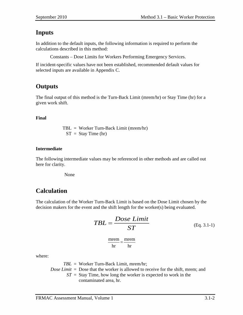
September 2010 Method 3.1 – Basic Worker Protection
FRMAC Assessment Manual, Volume 1 3.1-2
Inputs In addition to the default inputs, the following information is required to perform the calculations described in this method:
Constants – Dose Limits for Workers Performing Emergency Services.
If incident-specific values have not been established, recommended default values for selected inputs are available in Appendix C.
Outputs The final output of this method is the Turn-Back Limit (mrem/hr) or Stay Time (hr) for a given work shift.
Final
TBL = Worker Turn-Back Limit (mrem/hr) ST = Stay Time (hr)
Intermediate
The following intermediate values may be referenced in other methods and are called out here for clarity.
None
Calculation The calculation of the Worker Turn-Back Limit is based on the Dose Limit chosen by the decision makers for the event and the shift length for the worker(s) being evaluated.
Dose LimitTBL
ST= (Eq. 3.1-1)
mrem mrem=hr hr
where:
TBL = Worker Turn-Back Limit, mrem/hr; Dose Limit = Dose that the worker is allowed to receive for the shift, mrem; and ST = Stay Time, how long the worker is expected to work in the
contaminated area, hr.
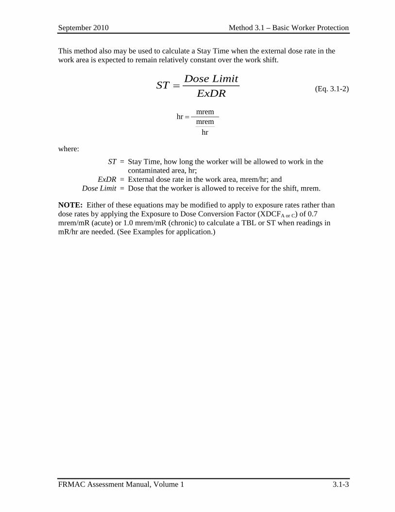
September 2010 Method 3.1 – Basic Worker Protection
FRMAC Assessment Manual, Volume 1 3.1-3
This method also may be used to calculate a Stay Time when the external dose rate in the work area is expected to remain relatively constant over the work shift.
Dose LimitST
ExDR= (Eq. 3.1-2)
mrem hr mremhr
=
where:
ST = Stay Time, how long the worker will be allowed to work in the contaminated area, hr;
ExDR = External dose rate in the work area, mrem/hr; and Dose Limit = Dose that the worker is allowed to receive for the shift, mrem.
NOTE: Either of these equations may be modified to apply to exposure rates rather than dose rates by applying the Exposure to Dose Conversion Factor (XDCFA or C) of 0.7 mrem/mR (acute) or 1.0 mrem/mR (chronic) to calculate a TBL or ST when readings in mR/hr are needed. (See Examples for application.)
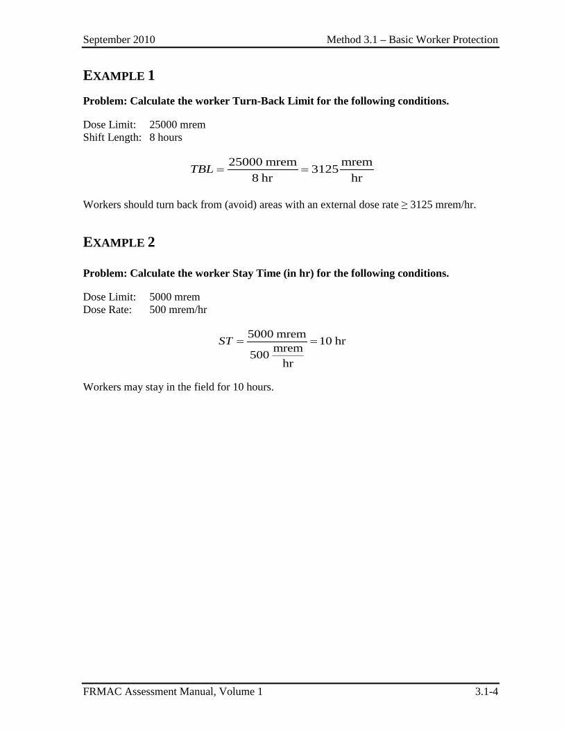
September 2010 Method 3.1 – Basic Worker Protection
FRMAC Assessment Manual, Volume 1 3.1-4
EXAMPLE 1
Problem: Calculate the worker Turn-Back Limit for the following conditions.
Dose Limit: 25000 mrem Shift Length: 8 hours
25000 mrem mrem3125
8 hr hrTBL = =
Workers should turn back from (avoid) areas with an external dose rate ≥ 3125 mrem/hr.
EXAMPLE 2
Problem: Calculate the worker Stay Time (in hr) for the following conditions.
Dose Limit: 5000 mrem Dose Rate: 500 mrem/hr
5000 mrem 10 hrmrem500hr
ST = =
Workers may stay in the field for 10 hours.
September 2010 Method 3.2 – Advanced Worker Protection
FRMAC Assessment Manual, Volume 1 3.2-1
METHOD 3.2 ADVANCED WORKER PROTECTION
Application This method is used to calculate the turn-back limit (TBL) for integrated dose (or exposure) for workers entering a contaminated area for a work shift.
The TBL:
• Represents the integrated external dose (or exposure) that will be expected to produce a total dose (external and internal) over a worker’s shift equal to the appropriate Protective Action Guide (PAG).
• Is derived from the PAGs for radiological emergency planning established by the Environmental Protection Agency (EPA) (EPA92) or the Department of Homeland Security (DHS) (DHS08) or other dose limits established for worker protection. A projected or measured dose (or exposure) value greater than the TBL indicates that the PAG has the potential to be exceeded.
• Is calculated from the Inhalation Dose Parameter for Deposition (InhDP_Dp) and the External Dose Parameter for Deposition (ExDP_Dp) values calculated in Method 2.1.
Discussion This method provides a means to establish emergency worker turn-back guidance based on monitoring results. These results may be from hand-held instruments, self-reading dosimeters (SRDs), or other mechanisms used to measure (or predict) integrated dose (or exposure).
Assumptions The following is an exception to the default assumptions:
1) The use of respiratory protection is addressed by this method.
Inputs In addition to the default inputs, the following information is required to perform the calculations described in this method:
Other Factors – Respiratory protection factor (RPF), Potassium Iodide protection factor (KIPF).
September 2010 Method 3.2 – Advanced Worker Protection
FRMAC Assessment Manual, Volume 1 3.2-2
Inhalation and External Dose Parameters for Deposition (InhDP_Dp and ExDP_Dp) for each radionuclide in the mixture, based on the start and end times and dose limit for the worker’s shift (calculated using Method 2.1).
NOTE: Consult with Health and Safety personnel to determine appropriate input values for the planned worker shift.
If incident-specific values have not been established, recommended default values for selected inputs are available in Appendix C.
Outputs The final output of this method is the turn-back limit (mrem or mR) for a given work shift.
Final
TBL_D = Worker Turn-Back Limit for Integrated External Dose (mrem) TBL_X = Worker Turn-Back Limit for Integrated External Exposure (mR)
Intermediate
The following intermediate values may be referenced in other methods and are called out here for clarity.
ExTDCFTP = External to Total Dose Conversion Factor, the ratio of the total dose (external + inhalation) to the external dose for a deposition of radioactive material over the time phase (TP) of interest, mreminh+external/mremexternal.
NOTE: This value is used to convert a measurement from a self- reading dosimeter into a dose that includes the effects of inhalation of resuspended material.
Calculation
1.0 Calculating the Worker Turn-Back Limit The calculation of the Turn-Back Limit for Integrated External Dose (TBL_D) is based on the Dose Limit chosen by the decision makers for the event and the ratio of Total (inhalation + external) Dose to External Dose.
NOTE: The default assumption is that this calculation will be performed to evaluate Whole-Body (Effective) dose. This method can also be used to evaluate TBLs for other organs by calculating the ExTDCF for that organ.
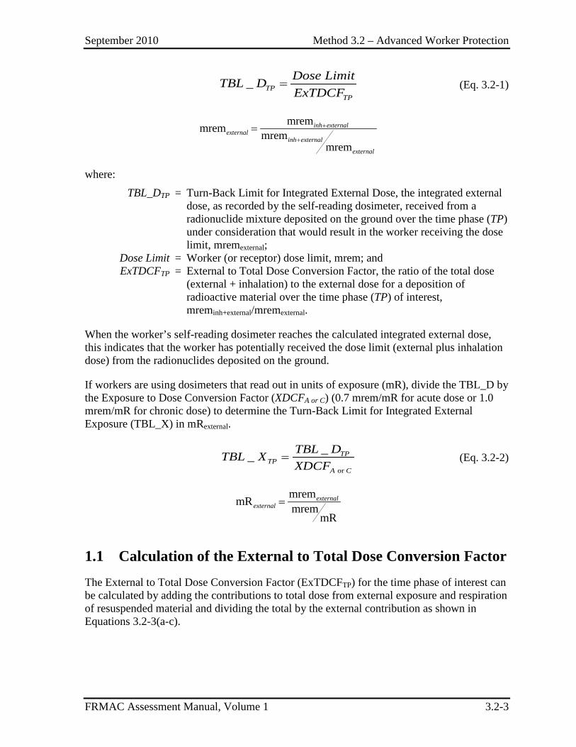
September 2010 Method 3.2 – Advanced Worker Protection
FRMAC Assessment Manual, Volume 1 3.2-3
_ TPTP
Dose LimitTBL DExTDCF
= (Eq. 3.2-1)
mremmrem mremmrem
inh externalexternal
inh external
external
+
+
=
where: TBL_DTP = Turn-Back Limit for Integrated External Dose, the integrated external
dose, as recorded by the self-reading dosimeter, received from a radionuclide mixture deposited on the ground over the time phase (TP) under consideration that would result in the worker receiving the dose limit, mremexternal;
Dose Limit = Worker (or receptor) dose limit, mrem; and ExTDCFTP = External to Total Dose Conversion Factor, the ratio of the total dose
(external + inhalation) to the external dose for a deposition of radioactive material over the time phase (TP) of interest, mreminh+external/mremexternal.
When the worker’s self-reading dosimeter reaches the calculated integrated external dose, this indicates that the worker has potentially received the dose limit (external plus inhalation dose) from the radionuclides deposited on the ground.
If workers are using dosimeters that read out in units of exposure (mR), divide the TBL_D by the Exposure to Dose Conversion Factor (XDCFA or C) (0.7 mrem/mR for acute dose or 1.0 mrem/mR for chronic dose) to determine the Turn-Back Limit for Integrated External Exposure (TBL_X) in mRexternal.
or
__ TPTP
A C
TBL DTBL XXDCF
= (Eq. 3.2-2)
mremmR mrem
mR
externalexternal =
1.1 Calculation of the External to Total Dose Conversion Factor The External to Total Dose Conversion Factor (ExTDCFTP) for the time phase of interest can be calculated by adding the contributions to total dose from external exposure and respiration of resuspended material and dividing the total by the external contribution as shown in Equations 3.2-3(a-c).
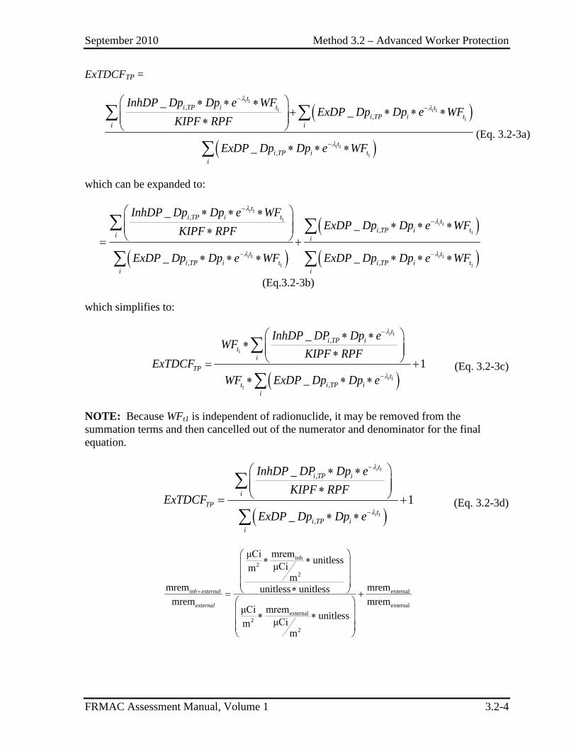
September 2010 Method 3.2 – Advanced Worker Protection
FRMAC Assessment Manual, Volume 1 3.2-4
ExTDCFTP =
( )
( )
1
1 1
1
1
1
,,
,
__
_
i
i
i
ti TP i t t
i TP i ti i
ti TP i t
i
InhDP Dp Dp e WFExDP Dp Dp e WF
KIPF RPF
ExDP Dp Dp e WF
λλ
λ
−−
−
∗ ∗ ∗+ ∗ ∗ ∗ ∗
∗ ∗ ∗
∑ ∑
∑(Eq. 3.2-3a)
which can be expanded to:
( )
( )
( )
1
11
1
1 1
1 1
,
,
, ,
__
_ _
i
i
i i
ti TP i t t
i TP i ti i
t ti TP i t i TP i t
i i
InhDP Dp Dp e WFExDP Dp Dp e WFKIPF RPF
ExDP Dp Dp e WF ExDP Dp Dp e WF
λ
λ
λ λ
−
−
− −
∗ ∗ ∗ ∗ ∗ ∗ ∗ = +
∗ ∗ ∗ ∗ ∗ ∗
∑ ∑
∑ ∑ (Eq.3.2-3b)
which simplifies to:
( )
1
1
1
1
,
,
_
1_
i
i
ti TP i
ti
TPt
t i TP ii
InhDP DP Dp eWF
KIPF RPFExTDCF
WF ExDP Dp Dp e
λ
λ
−
−
∗ ∗∗ ∗ = +∗ ∗ ∗
∑
∑ (Eq. 3.2-3c)
NOTE: Because WFt1 is independent of radionuclide, it may be removed from the summation terms and then cancelled out of the numerator and denominator for the final equation.
( )
1
1
,
,
_
1_
i
i
ti TP i
iTP
ti TP i
i
InhDP DP Dp eKIPF RPF
ExTDCFExDP Dp Dp e
λ
λ
−
−
∗ ∗ ∗ = +
∗ ∗
∑
∑ (Eq. 3.2-3d)
inh2
2
external
externalexternal
2
2
μCi mrem unitlessμCimm
mrem mremunitless unitlessmrem mrem
μCi mrem unitlessμCimm
inh external
external
+
∗ ∗ ∗ = + ∗ ∗
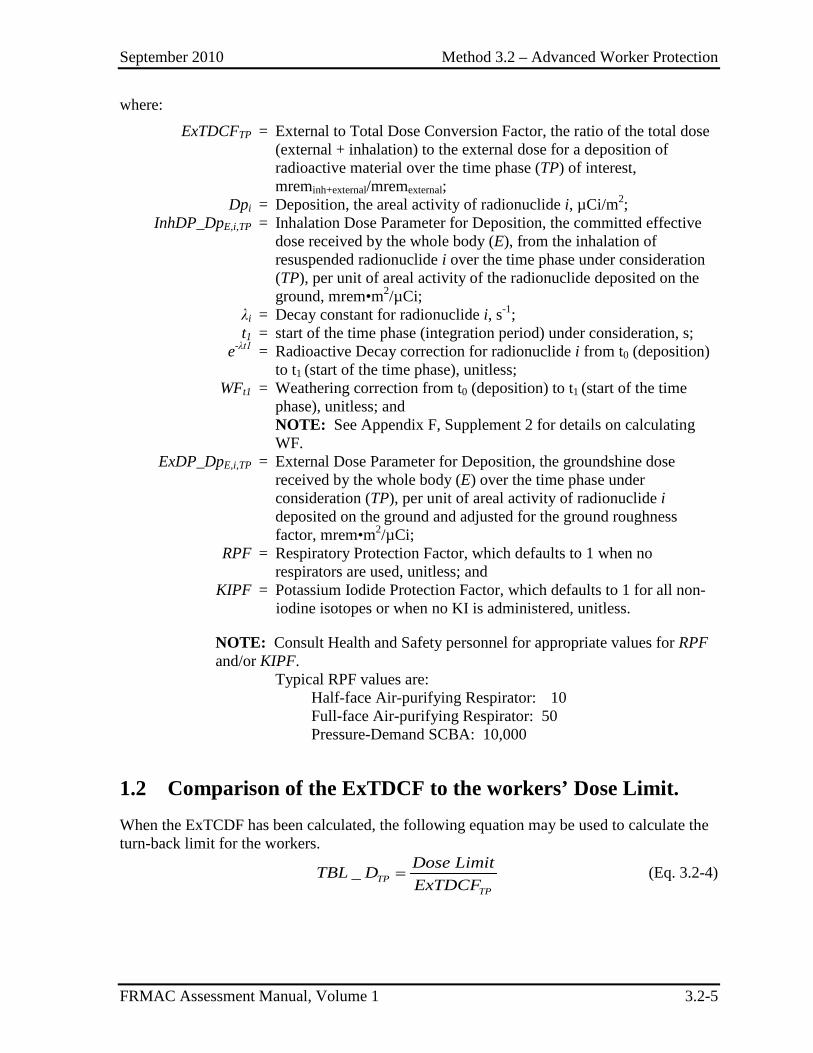
September 2010 Method 3.2 – Advanced Worker Protection
FRMAC Assessment Manual, Volume 1 3.2-5
where:
ExTDCFTP = External to Total Dose Conversion Factor, the ratio of the total dose (external + inhalation) to the external dose for a deposition of radioactive material over the time phase (TP) of interest, mreminh+external/mremexternal;
Dpi = Deposition, the areal activity of radionuclide i, µCi/m2; InhDP_DpE,i,TP = Inhalation Dose Parameter for Deposition, the committed effective
dose received by the whole body (E), from the inhalation of resuspended radionuclide i over the time phase under consideration (TP), per unit of areal activity of the radionuclide deposited on the ground, mrem•m2/µCi;
λi = Decay constant for radionuclide i, s-1; t1 = start of the time phase (integration period) under consideration, s; e-λt1 = Radioactive Decay correction for radionuclide i from t0 (deposition)
to t1 (start of the time phase), unitless; WFt1 = Weathering correction from t0 (deposition) to t1 (start of the time
phase), unitless; and NOTE: See Appendix F, Supplement 2 for details on calculating WF.
ExDP_DpE,i,TP = External Dose Parameter for Deposition, the groundshine dose received by the whole body (E) over the time phase under consideration (TP), per unit of areal activity of radionuclide i deposited on the ground and adjusted for the ground roughness factor, mrem•m2/µCi;
RPF = Respiratory Protection Factor, which defaults to 1 when no respirators are used, unitless; and
KIPF = Potassium Iodide Protection Factor, which defaults to 1 for all non-iodine isotopes or when no KI is administered, unitless.
NOTE: Consult Health and Safety personnel for appropriate values for RPF and/or KIPF.
Typical RPF values are: Half-face Air-purifying Respirator: 10 Full-face Air-purifying Respirator: 50 Pressure-Demand SCBA: 10,000
1.2 Comparison of the ExTDCF to the workers’ Dose Limit. When the ExTCDF has been calculated, the following equation may be used to calculate the turn-back limit for the workers.
_ TPTP
Dose LimitTBL DExTDCF
= (Eq. 3.2-4)
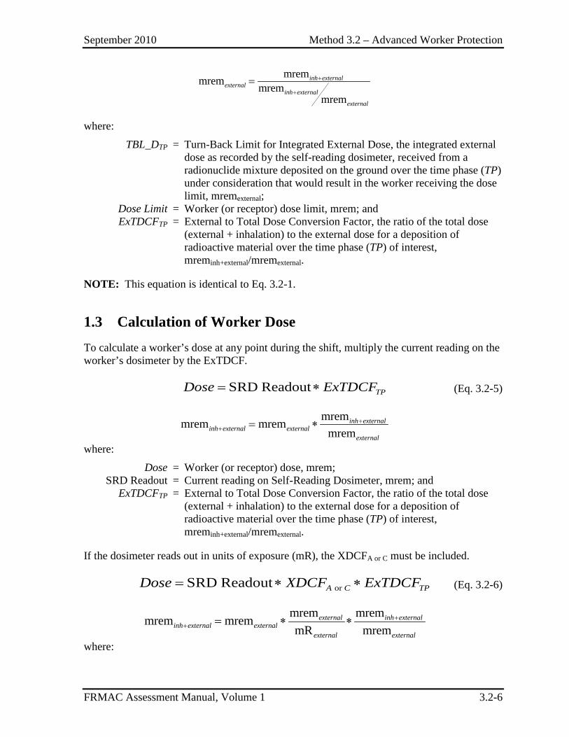
September 2010 Method 3.2 – Advanced Worker Protection
FRMAC Assessment Manual, Volume 1 3.2-6
mremmrem mremmrem
inh externalexternal
inh external
external
+
+
=
where:
TBL_DTP = Turn-Back Limit for Integrated External Dose, the integrated external dose as recorded by the self-reading dosimeter, received from a radionuclide mixture deposited on the ground over the time phase (TP) under consideration that would result in the worker receiving the dose limit, mremexternal;
Dose Limit = Worker (or receptor) dose limit, mrem; and ExTDCFTP = External to Total Dose Conversion Factor, the ratio of the total dose
(external + inhalation) to the external dose for a deposition of radioactive material over the time phase (TP) of interest, mreminh+external/mremexternal.
NOTE: This equation is identical to Eq. 3.2-1.
1.3 Calculation of Worker Dose To calculate a worker’s dose at any point during the shift, multiply the current reading on the worker’s dosimeter by the ExTDCF.
SRD Readout TPDose ExTDCF= ∗ (Eq. 3.2-5)
mremmrem mrem
mreminh external
inh external externalexternal
++ = ∗
where:
Dose = Worker (or receptor) dose, mrem; SRD Readout = Current reading on Self-Reading Dosimeter, mrem; and ExTDCFTP = External to Total Dose Conversion Factor, the ratio of the total dose
(external + inhalation) to the external dose for a deposition of radioactive material over the time phase (TP) of interest, mreminh+external/mremexternal.
If the dosimeter reads out in units of exposure (mR), the XDCFA or C must be included.
or SRD Readout A C TPDose XDCF ExTDCF= ∗ ∗ (Eq. 3.2-6)
mrem mremmrem mremmR mrem
external inh externalinh external external
external external
++ = ∗ ∗
where:
September 2010 Method 3.2 – Advanced Worker Protection
FRMAC Assessment Manual, Volume 1 3.2-7
XDCFA = Exposure to Dose Conversion Factor (acute), the constant used to convert external exposure (mR) to midline (bone marrow) dose (mrem), 0.7 mrem/mR.
XDCFC = Exposure to Dose Conversion Factor (chronic), the constant used to convert external exposure (mR) to deep tissue (1 cm) dose (mrem), 1.0 mrem/mR.
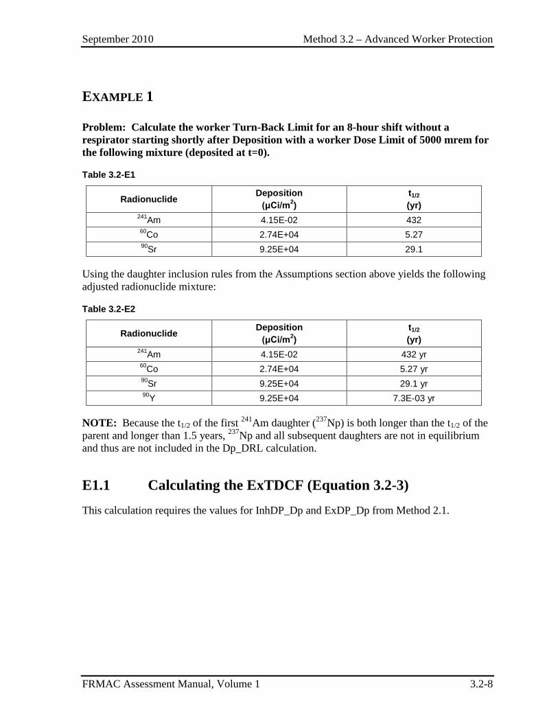
September 2010 Method 3.2 – Advanced Worker Protection
FRMAC Assessment Manual, Volume 1 3.2-8
EXAMPLE 1
Problem: Calculate the worker Turn-Back Limit for an 8-hour shift without a respirator starting shortly after Deposition with a worker Dose Limit of 5000 mrem for the following mixture (deposited at t=0).
Table 3.2-E1
Radionuclide Deposition (μCi/m2)
t1/2
(yr) 241Am 4.15E-02 432 60Co 2.74E+04 5.27 90Sr 9.25E+04 29.1
Using the daughter inclusion rules from the Assumptions section above yields the following adjusted radionuclide mixture:
Table 3.2-E2
Radionuclide Deposition (μCi/m2)
t1/2
(yr) 241Am 4.15E-02 432 yr 60Co 2.74E+04 5.27 yr 90Sr 9.25E+04 29.1 yr 90Y 9.25E+04 7.3E-03 yr
NOTE: Because the t1/2 of the first 241Am daughter (237Np) is both longer than the t1/2 of the parent and longer than 1.5 years, 237Np and all subsequent daughters are not in equilibrium and thus are not included in the Dp_DRL calculation.
E1.1 Calculating the ExTDCF (Equation 3.2-3) This calculation requires the values for InhDP_Dp and ExDP_Dp from Method 2.1.
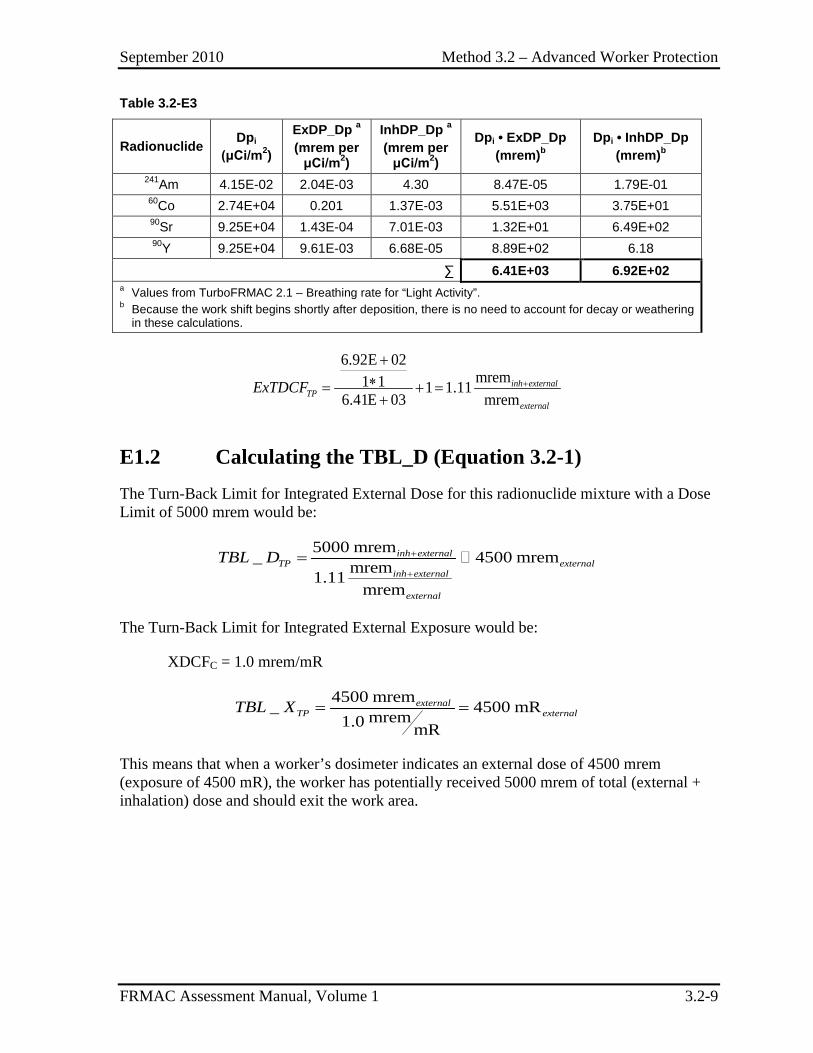
September 2010 Method 3.2 – Advanced Worker Protection
FRMAC Assessment Manual, Volume 1 3.2-9
Table 3.2-E3
Radionuclide Dpi
(μCi/m2)
ExDP_Dp a (mrem per
μCi/m2)
InhDP_Dp a (mrem per
μCi/m2)
Dpi • ExDP_Dp (mrem)b
Dpi • InhDP_Dp (mrem)b
241Am 4.15E-02 2.04E-03 4.30 8.47E-05 1.79E-01 60Co 2.74E+04 0.201 1.37E-03 5.51E+03 3.75E+01 90Sr 9.25E+04 1.43E-04 7.01E-03 1.32E+01 6.49E+02 90Y 9.25E+04 9.61E-03 6.68E-05 8.89E+02 6.18
∑ 6.41E+03 6.92E+02 a Values from TurboFRMAC 2.1 – Breathing rate for “Light Activity”. b Because the work shift begins shortly after deposition, there is no need to account for decay or weathering
in these calculations.
6.92E 02mrem1 1 1 1.11
6.41E 03 mreminh external
TPexternal
ExTDCF +
+∗= + =+
E1.2 Calculating the TBL_D (Equation 3.2-1) The Turn-Back Limit for Integrated External Dose for this radionuclide mixture with a Dose Limit of 5000 mrem would be:
5000 mrem_ 4500 mremmrem1.11mrem
inh externalTP external
inh external
external
TBL D +
+
=
The Turn-Back Limit for Integrated External Exposure would be:
XDCFC = 1.0 mrem/mR
4500 mrem_ 4500 mRmrem1.0 mR
externalTP externalTBL X = =
This means that when a worker’s dosimeter indicates an external dose of 4500 mrem (exposure of 4500 mR), the worker has potentially received 5000 mrem of total (external + inhalation) dose and should exit the work area.
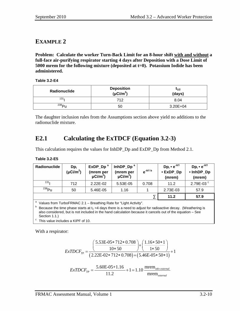
September 2010 Method 3.2 – Advanced Worker Protection
FRMAC Assessment Manual, Volume 1 3.2-10
EXAMPLE 2
Problem: Calculate the worker Turn-Back Limit for an 8-hour shift with and without a full-face air-purifying respirator starting 4 days after Deposition with a Dose Limit of 5000 mrem for the following mixture (deposited at t=0). Potassium Iodide has been administered.
Table 3.2-E4
Radionuclide Deposition (μCi/m2)
t1/2
(days) 131I 712 8.04
238Pu 50 3.20E+04
The daughter inclusion rules from the Assumptions section above yield no additions to the radionuclide mixture.
E2.1 Calculating the ExTDCF (Equation 3.2-3) This calculation requires the values for InhDP_Dp and ExDP_Dp from Method 2.1.
Table 3.2-E5
Radionuclide Dpi (μCi/m2)
ExDP_Dp a (mrem per
μCi/m2)
InhDP_Dp a (mrem per
μCi/m2) e-λt1 b
Dpi • e-λt1 • ExDP_Dp
(mrem)
Dpi • e-λt1 • InhDP_Dp
(mrem) 131I 712 2.22E-02 5.53E-05 0.708 11.2 2.79E-03 c
238Pu 50 5.46E-05 1.16 1 2.73E-03 57.9
∑ 11.2 57.9 a Values from TurboFRMAC 2.1 – Breathing Rate for “Light Activity”. b Because the time phase starts at t1 =4 days there is a need to adjust for radioactive decay. (Weathering is
also considered, but is not included in the hand calculation because it cancels out of the equation – See Section 1.1.)
c This value includes a KIPF of 10.
With a respirator:
( ) ( )
5.53E-05 712 0.708 1.16 50 110 50 1 50 1
2.22E-02 712 0.708 5.46E-05 50 1TPExTDCF
∗ ∗ ∗ ∗ + ∗ ∗ = +∗ ∗ + ∗ ∗
mrem5.60E-05+1.16 1 1.1011.2 mrem
inh externalTP
external
ExTDCF += + =
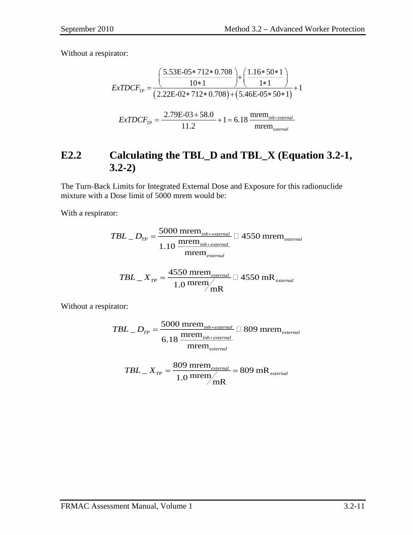
September 2010 Method 3.2 – Advanced Worker Protection
FRMAC Assessment Manual, Volume 1 3.2-11
Without a respirator:
( ) ( )
5.53E-05 712 0.708 1.16 50 110 1 1 1 1
2.22E-02 712 0.708 5.46E-05 50 1TPExTDCF
∗ ∗ ∗ ∗ + ∗ ∗ = +∗ ∗ + ∗ ∗
mrem2.79E-03 58.0 1 6.1811.2 mrem
inh externalTP
external
ExTDCF ++= + =
E2.2 Calculating the TBL_D and TBL_X (Equation 3.2-1, 3.2-2)
The Turn-Back Limits for Integrated External Dose and Exposure for this radionuclide mixture with a Dose limit of 5000 mrem would be:
With a respirator:
5000 mrem_ 4550 mremmrem1.10mrem
inh externalTP external
inh external
external
TBL D +
+
=
4550 mrem_ 4550 mRmrem1.0 mR
externalTP externalTBL X =
Without a respirator:
5000 mrem_ 809 mremmrem6.18mrem
inh externalTP external
inh external
external
TBL D +
+
=
809 mrem_ 809 mRmrem1.0 mR
externalTP externalTBL X = =

September 2010 Method 3.2 – Advanced Worker Protection
FRMAC Assessment Manual, Volume 1 3.2-12
This page intentionally left blank.
September 2010 Method 3.3 – Advanced Worker Protection Stay Time Calculation
FRMAC Assessment Manual, Volume 1 3.3-1
METHOD 3.3 ADVANCED WORKER PROTECTION STAY TIME CALCULATION
This method is reserved for future development.

September 2010 Method 3.3 – Advanced Worker Protection Stay Time Calculation
FRMAC Assessment Manual, Volume 1 3.3-2
This page intentionally left blank.
September 2010 Method 3.4 – Worker Skin Dose
FRMAC Assessment Manual, Volume 1 3.4-1
METHOD 3.4 WORKER SKIN DOSE
This method is reserved for future development.

September 2010 Method 3.4 – Worker Skin Dose
FRMAC Assessment Manual, Volume 1 3.4-2
This page intentionally left blank.
September 2010 Section 4 – Ingestion Pathway Methods
FRMAC Assessment Manual, Volume 1 4.0-1
SECTION 4. INGESTION PATHWAY METHODS
Effective Date
Introduction .............................................................................................. 4.0-3 9/2010
Method 4.1 Derived Intervention Level (DIL) ........................................ 4.1-1 9/2010
Method 4.2 Crop/Produce Derived Response Level (Crop_DRL) .......... 4.2-1 9/2010
Method 4.3 Milk Derived Response Level (Milk_DRL)......................... 4.3-1 9/2010
Method 4.4 Meat Derived Response Level (Meat_DRL) ........................ 4.4-1 9/2010
Method 4.5 Ingestion Dose ...................................................................... 4.5-1 9/2010
Method 4.6 Projecting Contamination Levels in Food ............................ 4.6-1 9/2010
Method 4.7 Inadvertent Soil Ingestion Dose ........................................... 4.7-1 9/2010

September 2010 Section 4 – Ingestion Pathway Methods
FRMAC Assessment Manual, Volume 1 4.0-2
This page intentionally left blank.
September 2010 Section 4 – Ingestion Pathway Methods
FRMAC Assessment Manual, Volume 1 4.0-3
INTRODUCTION TO INGESTION PATHWAY METHODS
These methods are used to assess measured or projected environmental measurements for comparison to the FDA DILs for radioactive contamination in food (FDA98).
The FDA has established DILs for contamination in food for a list of radionuclides and has specified a method to calculate DILs for all other radionuclides. The DILs are based on PAGs of 0.5 rem Committed Effective Dose (E50) and 5 rem to any specific organ (HT,50), whichever is more limiting. FDA Ingestion PAGs are presented in Appendix C, Table 2-2, and DILs for selected radionuclides (including the full FDA list) are presented in Appendix C, Table 8.
Dose calculations assume radionuclide concentrations are for foods as prepared for consumption and ingestion is assumed to take place for a period of one year (or less for radionuclides with half lives < 54 days – See Method 4.1).
These methods may include the use of Transfer Factors (TFs) to estimate the concentration of radionuclides in food products. Transfer factors are the ratio of the concentration of a radionuclide in food products to the concentration in the source medium such as soil, plant forage, or water (PNNL03).
The equations presented in these methods use the following assumptions about Transfer Factors:
• Transfer Factors assume a long-term exposure during which equilibrium is reached. • Transfer Factors used in these methods for terrestrial plants are based on dry weight. • Transfer Factors used in these methods for animal products and aquatic plants are
based on wet weight.
These methods consider both mature (ready for harvest) and immature food products. Calculations for mature products assume that the product will enter the food supply immediately and therefore do not include the effects of weathering and radioactive decay. Calculations for immature products include the effects of weathering and radioactive decay until the crops are ready for harvest and consumption. Both types of calculations address decay during transport from the field to the table.
For the ingestion pathway, daughter radionuclides in transient (or secular) equilibrium are excluded from independent analysis because their contribution to dose is included in the dose coefficient of the ultimate parent. Daughter radionuclides with a half life greater than 6 hours are analyzed separately from the parent radionuclide because it may be possible to get food prepared for consumption before significant decay occurs.
September 2010 Section 4 – Ingestion Pathway Methods
FRMAC Assessment Manual, Volume 1 4.0-4
This page intentionally left blank.
September 2010 Method 4.1 – Derived Intervention Levels
FRMAC Assessment Manual, Volume 1 4.1-1
METHOD 4.1 DERIVED INTERVENTION LEVELS
Application This method has been developed to calculate Derived Intervention Levels (DILs) for radioactive material deposited on consumables.
The DIL:
• Represents the activity concentration (µCi/kgwet) of radioactive material found in food that, in the absence of any intervention, could lead to an individual receiving a dose equal to the appropriate Protective Action Guide (PAG) if consumed over 1 year.
• Is derived from the PAG for radiological emergency planning established by the Food and Drug Agency (FDA) (FDA98). A projected or measured value of radioactivity greater than the DIL indicates that the PAG has the potential to be exceeded.
• Applies to the activity concentration in the food “as prepared for consumption” or “wet.”
• Is applied during the first year after an incident and based on the most sensitive population (age group) and target organ to provide a large margin of safety to the public.
• Is used to create data products and define activity concentration levels to assist decision makers in determining where it may be advisable to implement protective actions (e.g., sheltering livestock, embargos, special product handling).
Discussion DILs were recommended by the FDA in 1998 as the radionuclide activity concentration in food at which point protective actions should be considered. Food with activity concentrations below the DIL is permitted to move in commerce without restriction. However, local decision makers have the flexibility to apply alternate limits in special circumstances.
The FDA established DILs for 9 principle isotopes in 5 groups, 15 secondary isotopes, and provided a method to calculate DILs. The nuclides with FDA-provided DILs are shown in Table 4.1-1 below and in Appendix C, Table 8.
FRMAC does not have the authority to calculate or use different DILs for radionuclides for which the FDA has provided recommended values unless alternate values are requested by the Advisory Team or local decision makers. FRMAC can calculate DILs for the
September 2010 Method 4.1 – Derived Intervention Levels
FRMAC Assessment Manual, Volume 1 4.1-2
radionuclides for which the FDA does not provide recommended values, but these values are not automatically approved by the FDA and must receive approval from the Advisory Team or local decision makers before they are used.
Assumptions The FRMAC radiological assessment calculations use the default assumptions established by the FDA. The following default assumptions are used in this method:
1) DILs apply to individual radionuclides (or FDA-specified groups of radionuclides); there is no sum-of-fraction rule (except for 103Ru and 106Ru).
2) DILs apply only to the parent radionuclide in a chain. DO NOT calculate a DIL for a daughter radionuclide independently unless it exists in the mixture as a separate parent (i.e., in excess of its equilibrium concentration).
3) DILs are based on average annual dietary intake (kgwet/yr) of all dietary components (e.g., produce, grains, meat, etc.), including tap water used for drinking.
4) Annual intake is adjusted for short-lived (t1/2 < 54 days) radionuclides to account for radioactive decay.
5) Annual intake varies by age group (3 month, 1 yr, 5 yr, 10 yr, 15 yr, and adult).
6) DILs are applicable to foods as prepared for consumption or “wet”. To compare with analytical results it may be necessary to convert to “dry weight,” see Method 5.2.
7) ICRP 26 Ingestion Dose Conversion Factors should not be used to calculate DILs because they only consider the adult receptor (ICRP77).
8) The default Ingestion PAGs are: • 500 mrem to the whole body or • 5000 mrem to an individual organ, whichever is more limiting.
9) Inadvertent ingestion of soil is not included in these methods. If ingestion of soil is a significant dose pathway (i.e., >10% of the total dose), it should be addressed separately. (See Method 4.7).
10) Default calculations for non-FDA-listed radionuclides use the International Commission on Radiological Protection (ICRP) 60+ dosimetry model.
Inputs The following information is required to perform the methods described in this section:
Data – Composition of the deposited radionuclide mixture (radionuclides and concentration). This information may come from predictive analysis (models) or field data (monitoring and/or samples).
Other Factors – Decay of radionuclides during the time period under consideration.
September 2010 Method 4.1 – Derived Intervention Levels
FRMAC Assessment Manual, Volume 1 4.1-3
Constants – Fraction of diet contaminated, daily food intake rate, ingestion dose coefficient, dose limits (e.g., FDA PAGs).
If incident-specific values have not been established, recommended default values for selected inputs are available in Appendix C.
NOTE: Many of the terms in the methods are dependent on variables (e.g., time phase, target organ, PAG, etc.). When critical, these dependencies are shown as subscripts to the appropriate terms. (See Appendix B for the variable list.)
Outputs The final output of this method is the DIL for a radionuclide contaminant.
Final
DILi = Derived Intervention Level, the activity concentration level of radionuclide i at which the ingestion dose to the most sensitive population (age group) and target organ has the potential to exceed the applicable ingestion PAG, µCi/kgwet.
Intermediate
The following intermediate values may be referenced in other methods and are called out here for clarity.
None
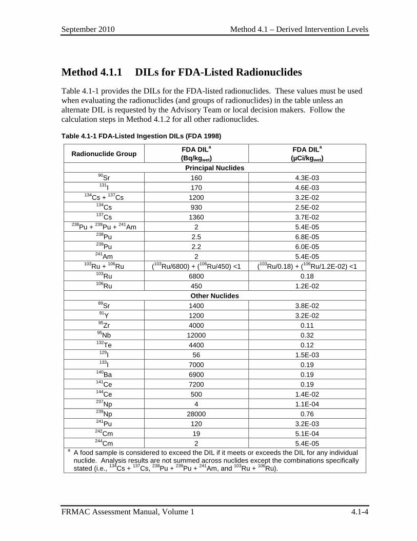
September 2010 Method 4.1 – Derived Intervention Levels
FRMAC Assessment Manual, Volume 1 4.1-4
Method 4.1.1 DILs for FDA-Listed Radionuclides Table 4.1-1 provides the DILs for the FDA-listed radionuclides. These values must be used when evaluating the radionuclides (and groups of radionuclides) in the table unless an alternate DIL is requested by the Advisory Team or local decision makers. Follow the calculation steps in Method 4.1.2 for all other radionuclides.
Table 4.1-1 FDA-Listed Ingestion DILs (FDA 1998)
Radionuclide Group FDA DILa (Bq/kgwet)
FDA DILa (µCi/kgwet)
Principal Nuclides 90Sr 160 4.3E-03 131I 170 4.6E-03
134Cs + 137Cs 1200 3.2E-02 134Cs 930 2.5E-02 137Cs 1360 3.7E-02
238Pu + 239Pu + 241Am 2 5.4E-05 238Pu 2.5 6.8E-05 239Pu 2.2 6.0E-05 241Am 2 5.4E-05
103Ru + 106Ru (103Ru/6800) + (106Ru/450) <1 (103Ru/0.18) + (106Ru/1.2E-02) <1 103Ru 6800 0.18 106Ru 450 1.2E-02
Other Nuclides 89Sr 1400 3.8E-02 91Y 1200 3.2E-02 95Zr 4000 0.11 95Nb 12000 0.32 132Te 4400 0.12
129I 56 1.5E-03 133I 7000 0.19
140Ba 6900 0.19 141Ce 7200 0.19 144Ce 500 1.4E-02 237Np 4 1.1E-04 239Np 28000 0.76 241Pu 120 3.2E-03 242Cm 19 5.1E-04 244Cm 2 5.4E-05
a A food sample is considered to exceed the DIL if it meets or exceeds the DIL for any individual nuclide. Analysis results are not summed across nuclides except the combinations specifically stated (i.e., 134Cs + 137Cs, 238Pu + 239Pu + 241Am, and 103Ru + 106Ru).

September 2010 Method 4.1 – Derived Intervention Levels
FRMAC Assessment Manual, Volume 1 4.1-5
Method 4.1.2 DILs for Non-FDA-Listed Radionuclides
Calculation This method uses the FDA approach for all calculations.
DIL calculations can be complex, given the number of age group/organ combinations that need to be calculated to determine the most restrictive value for each radionuclide. Therefore the user is urged to use a computer code, such as Turbo FRMAC, to complete these calculations. All calculated values must be approved by an FDA representative on the Advisory Team prior to publication.
Equation 4.1-1 shows the DIL calculation.
, ,, , ,
organorgan age i
age i age i organ age i
PAGDIL
FDC DFIR EDI IngDC=
∗ ∗ ∗ (Eq. 4.1-1)
wetwet
μCi mremkg mremkg unitless d
d μCi
=∗ ∗ ∗
where:
DILorgan,age,i = Derived Intervention Level, the activity concentration level of radionuclide i at which the ingestion dose to the most sensitive population (age group) and target organ has the potential to exceed the applicable ingestion PAG, µCi/kgwet;
PAGorgan = Protective Action Guide, as specified by the FDA or local authorities, for the target organ, mrem;
FDCage,i = Fraction of Diet Contaminated, default value of 0.3, (except 132Te, 131I, 133I and 239Np in the diet of an infant (3 months and 1 yr) for which it is 1.0), unitless;
NOTE: If there is convincing local information that the actual FDC is considerably different, local authorities may decide to use a different FDC.
DFIRage = Daily Food Intake Rate, the daily intake rate for the age group under consideration (see Appendix C, Table 10), kgwet/d;
EDIi = Effective Days of Intake, the number of days required for the radionuclide to decay to <1% of its initial activity (set to 365 if value is greater), d; and
( )1/2
ln 0.01 ln 2 where i
i ii
EDIt
λλ
−= = (Eq. 4.1-2)
NOTE: If the radionuclide half life is greater than 54 days, the EDIi = 365 days.
September 2010 Method 4.1 – Derived Intervention Levels
FRMAC Assessment Manual, Volume 1 4.1-6
IngDCorgan,age,i = Ingestion Dose Coefficient, the ingestion pathway dose coefficient for the target organ for a specific age group for radionuclide i, mrem/µCi.
This calculation will determine a DIL for one age group and one organ. To determine the most restrictive value for a given radionuclide:
• Calculate the DIL for the whole body and for the organ with the highest IngDC for each age group.
• Apply the DIL for the age group and organ with the most conservative (lowest) activity concentration level (µCi/kgwet).
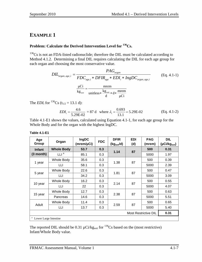
September 2010 Method 4.1 – Derived Intervention Levels
FRMAC Assessment Manual, Volume 1 4.1-7
EXAMPLE 1
Problem: Calculate the Derived Intervention Level for 136Cs.
136Cs is not an FDA-listed radionuclide; therefore the DIL must be calculated according to Method 4.1.2. Determining a final DIL requires calculating the DIL for each age group for each organ and choosing the most conservative value.
, ,, , ,
organorgan age i
age i age i organ age i
PAGDIL
FDC DFIR EDI IngDC=
∗ ∗ ∗ (Eq. 4.1-1)
wetwet
μCi mremkg mremkg unitless d
d μCi
=∗ ∗ ∗
The EDIi for 136Cs (t1/2 = 13.1 d):
4.6 0.693 = 87 d where 5.29E-025.29E-02 13.1i iEDI λ= = = (Eq. 4.1-2)
Table 4.1-E1 shows the values, calculated using Equation 4.1-1, for each age group for the Whole Body and for the organ with the highest IngDC.
Table 4.1-E1
Age Group Organ IngDC
(mrem/µCi) FDC DFIR (kgwet/d)
EDI (d)
PAG (mrem)
DIL (µCi/kgwet)
Infant (3 month)
Whole Body 53.7 0.3 1.14 87
500 0.31 LLI a 85.1 0.3 5000 1.97
1 year Whole Body 35.6 0.3
1.38 87 500 0.39
LLI 58.1 0.3 5000 2.39
5 year Whole Body 22.6 0.3
1.81 87 500 0.47
LLI 34.2 0.3 5000 3.09
10 year Whole Body 16.2 0.3
2.14 87 500 0.55
LLI 22 0.3 5000 4.07
15 year Whole Body 12.7 0.3
2.38 87 500 0.63
Pancreas 14.6 0.3 5000 5.51
Adult Whole Body 11.4 0.3
2.59 87 500 0.65
LLI 13.7 0.3 5000 5.40
Most Restrictive DIL 0.31 a Lower Large Intestine
The reported DIL should be 0.31 µCi/kgwet for 136Cs based on the (most restrictive) Infant/Whole Body value.
September 2010 Method 4.1 – Derived Intervention Levels
FRMAC Assessment Manual, Volume 1 4.1-8
This page intentionally left blank.
September 2010 Method 4.2 – Crop DRL
FRMAC Assessment Manual, Volume 1 4.2-1
METHOD 4.2 CROP/PRODUCE INGESTION DERIVED RESPONSE LEVELS
Application This method has been developed to calculate Ingestion Derived Response Levels for radioactive material deposited on crop/produce.
The Crop/Produce Ingestion Derived Response Level (Crop_DRL):
• Represents the ground concentration, or areal activity (µCi/m2), of radionuclide i that will be expected to cause the crop/produce growing in that area to exceed the Derived Intervention Level (DIL) for that radionuclide.
• Is indirectly derived (through the DIL) from the PAG for radiological emergency planning established by the Food and Drug Agency (FDA) (FDA98). A projected or measured deposition value greater than the Crop_DRL indicates that the PAG has the potential to be exceeded.
• Is applied during the first year after an incident and based on the most sensitive population (age group) and target organ to provide a large margin of safety to the public.
• Is used to create data products and define contamination levels to assist decision makers in determining where it may be advisable to conduct sampling to evaluate the potential for implementing protective actions (e.g., sheltering livestock, embargos, special product handling).
• Is calculated using the DIL calculated in Method 4.1
Discussion The Crop_DRL predicts the amount of radioactivity deposited on a crop (µCi/m2) that would cause the crop to exceed the DIL. Sampling efforts should concentrate on the area where the contamination is equal to the Crop_DRL to determine if the DIL has been exceeded in those areas. Protective actions should be considered in areas where the DIL is exceeded. FDA guidance permits food with radioactivity concentrations below the DIL to move in commerce without restriction. However, the FDA and local decision makers have flexibility in whether to apply restrictions in special circumstances.
FRMAC does not have the authority to calculate or use different DILs for radionuclides for which the FDA has provided recommended values unless alternate values are requested by the Advisory Team or local decision makers. FRMAC can calculate DILs for the
September 2010 Method 4.2 – Crop DRL
FRMAC Assessment Manual, Volume 1 4.2-2
radionuclides for which the FDA does not provide recommended values, but these values are not automatically approved by the FDA and must receive approval from the Advisory Team or local decision makers before they are used.
Assumptions The FRMAC radiological assessment calculations use the default assumptions established by the FRMAC Assessment Working Group. The following default assumptions are used in this method:
Crop DRLs:
1) Apply to individual radionuclides; there is no sum-of-fraction rule (except for the FDA-listed 103Ru and 106Ru).
2) Are based on the most restrictive DIL for each radionuclide based on age group and target organ. See Method 4.1 for DIL calculation assumptions.
3) Apply to the plant as a whole and do not predict contamination of only the edible portions (e.g., apples on the tree.)
4) Assume a crop yield of 2 kgwet/m2 for fresh produce.
5) Assume a soil density of 1600 kgsoil/m3.
6) Assume a mixing depth of 1.0E-03 m for the first growing season and 0.15 after plowing (EPA89).
7) Assume a half life of 15 days for material weathering off plant material
8) Assume a Time to Market of 1 day for fresh produce.
9) Assume, for immature crops, that the crop will remain growing in the contaminated soil for a period of time sufficient to reach equilibrium.
10) Are calculated for food as prepared for consumption. To compare with analytical results it may be necessary to convert to “dry weight,” see Method 5.2.
11) Use Crop Retention Factors for fresh produce of: • 1.0 for radioiodine and • 0.2 for all other radionuclides.
12) DRLs for FDA grouped radionuclides (e.g., 134Cs + 137Cs) are adjusted for decay during Field Time and Time to Market using the decay constant for the longest-lived group member.
Inputs The following information is required to perform the methods described in this section:
Data – Composition of the deposited radionuclide mixture (radionuclides and concentration). This information may come from predictive analysis (models) or field data (monitoring and/or samples).
September 2010 Method 4.2 – Crop DRL
FRMAC Assessment Manual, Volume 1 4.2-3
Constants – Crop Retention Factor, Crop Yield, Transfer Factors for different food types and for each radionuclide.
Other Factors – Decay and weathering of radionuclides during the time period under consideration, soil mixing depth.
Appropriate DIL for each radionuclide – Calculated using Method 4.1.
If incident-specific values have not been established, recommended default values for selected inputs are available in Appendix C.
NOTE: Many of the terms in the methods are dependent on variables (e.g., time phase, target organ, PAG, etc.). When critical, these dependencies are shown as subscripts to the appropriate terms. (See Appendix B for the variable list.)
Outputs The final output of this method is the Crop_DRL value for a radionuclide contaminant on the growing area.
Final
Crop_DRLmat,i = Ingestion Derived Response Level for mature Crop/Produce, the ground concentration, or areal activity (µCi/m2), of radionuclide i that will be expected to cause the crop/produce growing in that area to exceed the applicable Derived Intervention Level (DIL), µCi/kgwet.
Crop_DRLimm,i = Ingestion Derived Response Level for immature Crop/Produce, the ground concentration, or areal activity (µCi/m2), of radionuclide i that will be expected to cause the crop/produce growing in that area to exceed the applicable Derived Intervention Level (DIL), µCi/kgwet.
Intermediate
The following intermediate values may be referenced in other methods and are called out here for clarity.
None
Method 4.2.1 Crop_DRL for Mature Crop/Produce This method is used to evaluate fresh produce that will be harvested for immediate consumption. Because of the short time frame involved, the following have not been included in this method:
• Reduction in radioactivity due to weathering.
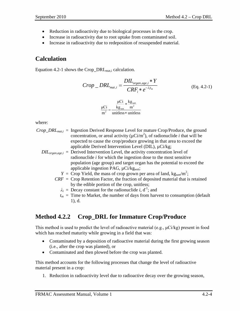
September 2010 Method 4.2 – Crop DRL
FRMAC Assessment Manual, Volume 1 4.2-4
• Reduction in radioactivity due to biological processes in the crop. • Increase in radioactivity due to root uptake from contaminated soil. • Increase in radioactivity due to redeposition of resuspended material.
Calculation Equation 4.2-1 shows the Crop_DRLmat,i calculation.
, ,
,_i m
organ age imat i t
i
DIL YCrop DRL
CRF e λ−
∗=
∗ (Eq. 4.2-1)
wet2
wet2
μCi kgμCi kg mm unitless unitless
∗=
∗
where:
Crop_DRLmat,i = Ingestion Derived Response Level for mature Crop/Produce, the ground concentration, or areal activity (µCi/m2), of radionuclide i that will be expected to cause the crop/produce growing in that area to exceed the applicable Derived Intervention Level (DIL), µCi/kg;
DILorgan,age,i = Derived Intervention Level, the activity concentration level of radionuclide i for which the ingestion dose to the most sensitive population (age group) and target organ has the potential to exceed the applicable ingestion PAG, µCi/kgwet;
Y = Crop Yield, the mass of crop grown per area of land, kgwet/m2; CRF = Crop Retention Factor, the fraction of deposited material that is retained
by the edible portion of the crop, unitless; λi = Decay constant for the radionuclide i, d-1; and tm = Time to Market, the number of days from harvest to consumption (default
1), d.
Method 4.2.2 Crop_DRL for Immature Crop/Produce This method is used to predict the level of radioactive material (e.g., μCi/kg) present in food which has reached maturity while growing in a field that was:
• Contaminated by a deposition of radioactive material during the first growing season (i.e., after the crop was planted), or
• Contaminated and then plowed before the crop was planted.
This method accounts for the following processes that change the level of radioactive material present in a crop:
1. Reduction in radioactivity level due to radioactive decay over the growing season,
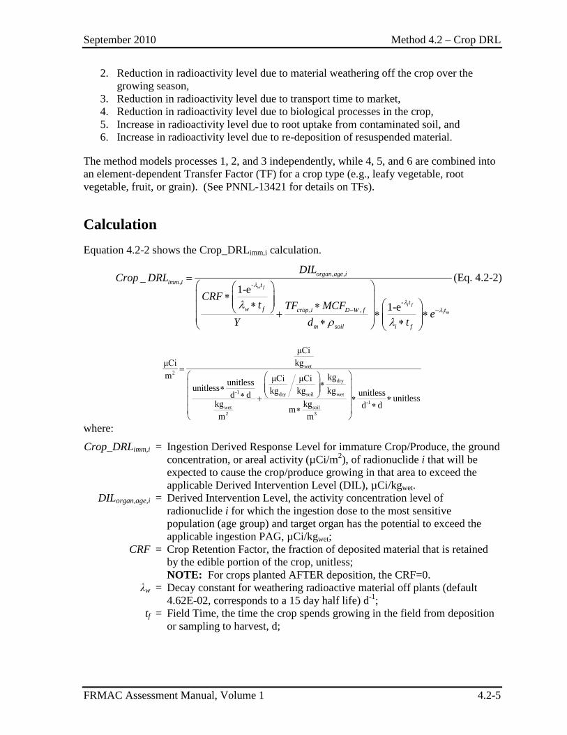
September 2010 Method 4.2 – Crop DRL
FRMAC Assessment Manual, Volume 1 4.2-5
2. Reduction in radioactivity level due to material weathering off the crop over the growing season,
3. Reduction in radioactivity level due to transport time to market, 4. Reduction in radioactivity level due to biological processes in the crop, 5. Increase in radioactivity level due to root uptake from contaminated soil, and 6. Increase in radioactivity level due to re-deposition of resuspended material.
The method models processes 1, 2, and 3 independently, while 4, 5, and 6 are combined into an element-dependent Transfer Factor (TF) for a crop type (e.g., leafy vegetable, root vegetable, fruit, or grain). (See PNNL-13421 for details on TFs).
Calculation Equation 4.2-2 shows the Crop_DRLimm,i calculation.
, ,, -
-, ,
_1-e
1-e
w f
i f
i m
organ age iimm i t
tw f crop i D W f t
m soil i f
DILCrop DRL
CRFt TF MCF
eY d t
λ
λλλ
ρ λ− −
=
∗ ∗ ∗ + ∗ ∗ ∗ ∗
(Eq. 4.2-2)
wet2
dry
-1 dry soil wet-1
wet soil2 3
μCikgμCi
m kgμCi μCiunitlessunitless kg kg kg unitlessd d unitlesskg kg d dmm m
=
∗ ∗ ∗ + ∗ ∗ ∗∗
where:
Crop_DRLimm,i = Ingestion Derived Response Level for immature Crop/Produce, the ground concentration, or areal activity (µCi/m2), of radionuclide i that will be expected to cause the crop/produce growing in that area to exceed the applicable Derived Intervention Level (DIL), µCi/kgwet.
DILorgan,age,i = Derived Intervention Level, the activity concentration level of radionuclide i for which the ingestion dose to the most sensitive population (age group) and target organ has the potential to exceed the applicable ingestion PAG, µCi/kgwet;
CRF = Crop Retention Factor, the fraction of deposited material that is retained by the edible portion of the crop, unitless;
NOTE: For crops planted AFTER deposition, the CRF=0. λw = Decay constant for weathering radioactive material off plants (default
4.62E-02, corresponds to a 15 day half life) d-1; tf = Field Time, the time the crop spends growing in the field from deposition
or sampling to harvest, d;
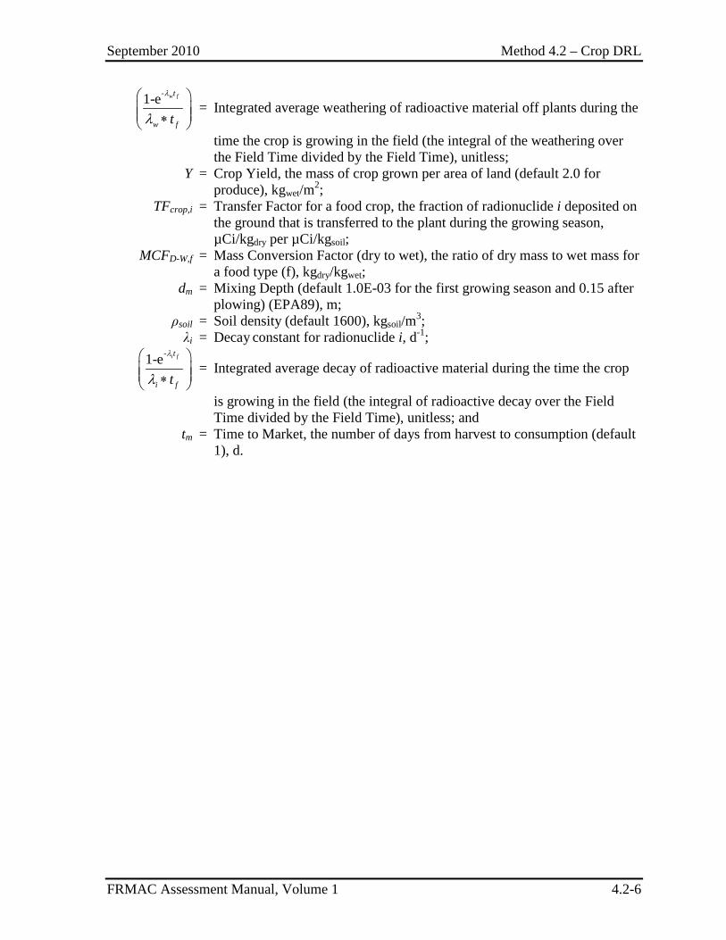
September 2010 Method 4.2 – Crop DRL
FRMAC Assessment Manual, Volume 1 4.2-6
-1-e w ft
w ft
λ
λ ∗
= Integrated average weathering of radioactive material off plants during the
time the crop is growing in the field (the integral of the weathering over the Field Time divided by the Field Time), unitless;
Y = Crop Yield, the mass of crop grown per area of land (default 2.0 for produce), kgwet/m2;
TFcrop,i = Transfer Factor for a food crop, the fraction of radionuclide i deposited on the ground that is transferred to the plant during the growing season, µCi/kgdry per µCi/kgsoil;
MCFD-W,f = Mass Conversion Factor (dry to wet), the ratio of dry mass to wet mass for a food type (f), kgdry/kgwet;
dm = Mixing Depth (default 1.0E-03 for the first growing season and 0.15 after plowing) (EPA89), m;
ρsoil = Soil density (default 1600), kgsoil/m3; λi = Decay constant for radionuclide i, d-1;
-1-e i ft
i ft
λ
λ ∗
= Integrated average decay of radioactive material during the time the crop
is growing in the field (the integral of radioactive decay over the Field Time divided by the Field Time), unitless; and
tm = Time to Market, the number of days from harvest to consumption (default 1), d.
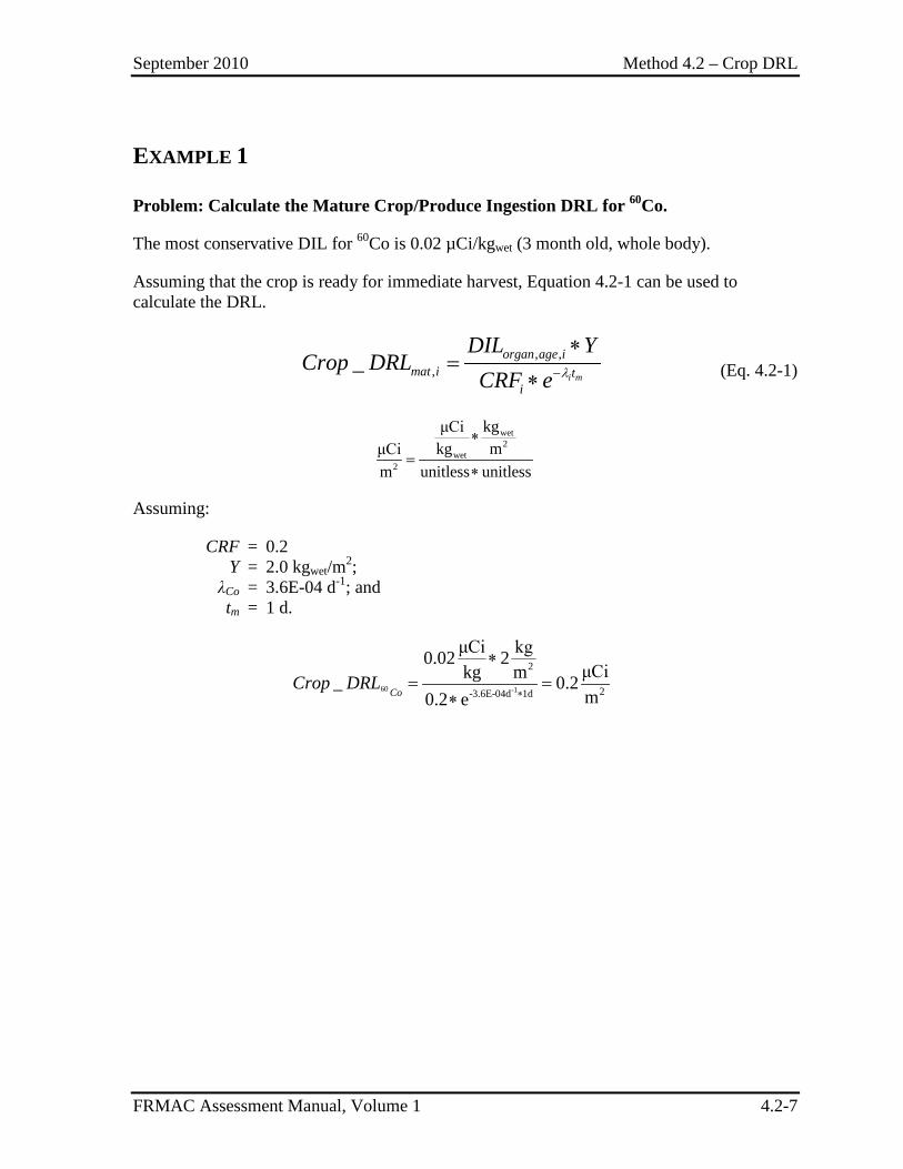
September 2010 Method 4.2 – Crop DRL
FRMAC Assessment Manual, Volume 1 4.2-7
EXAMPLE 1
Problem: Calculate the Mature Crop/Produce Ingestion DRL for 60Co.
The most conservative DIL for 60Co is 0.02 µCi/kgwet (3 month old, whole body).
Assuming that the crop is ready for immediate harvest, Equation 4.2-1 can be used to calculate the DRL.
, ,
,_i m
organ age imat i t
i
DIL YCrop DRL
CRF e λ−
∗=
∗ (Eq. 4.2-1)
wet2
wet2
kgμCikg mμCi
m unitless unitless
∗=
∗
Assuming:
CRF = 0.2 Y = 2.0 kgwet/m2; λCo = 3.6E-04 d-1; and tm = 1 d.
60 -1
2
2-3.6E-04d 1d
μCi kg0.02 2μCikg m_ 0.2m0.2 eCo
Crop DRL∗
∗= =
∗
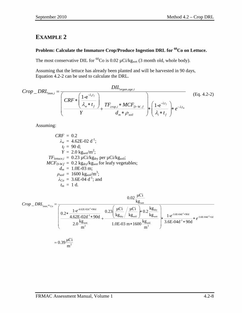
September 2010 Method 4.2 – Crop DRL
FRMAC Assessment Manual, Volume 1 4.2-8
EXAMPLE 2
Problem: Calculate the Immature Crop/Produce Ingestion DRL for 60Co on Lettuce.
The most conservative DIL for 60Co is 0.02 µCi/kgwet (3 month old, whole body).
Assuming that the lettuce has already been planted and will be harvested in 90 days, Equation 4.2-2 can be used to calculate the DRL.
, ,, -
-, ,
_1-e
1-e
w f
i f
i m
organ age iimm i t
tw f crop i D W f t
m soil i f
DILCrop DRL
CRFt TF MCF
eY d t
λ
λλλ
ρ λ− −
=
∗ ∗ ∗ + ∗ ∗ ∗ ∗
(Eq. 4.2-2)
Assuming:
CRF = 0.2 λw = 4.62E-02 d-1; tf = 90 d; Y = 2.0 kgwet/m2; TFlettuce,i = 0.23 µCi/kgdry per µCi/kgsoil; MCFD-W,f = 0.2 kgdry/kgwet for leafy vegetables; dm = 1.0E-03 m; ρsoil = 1600 kgsoil/m3; λCo = 3.6E-04 d-1; and tm = 1 d.
60
-1
-1-
wet,
-4.62E-02d 90d dry
-3.6E-04d 90d-1 dry soil wet -3.6E-04d-1
wet soil2 3
μCi0.02kg_
kgμCi μCi1- 0.23 0.20.2 kg kg kg 1-4.62E-02d 90dkg kg 3.6E-04d 90d2.0 1.0E-03 m 1600m m
imm CoCrop DRL
ee e
∗
∗
=
∗ ∗ ∗ + ∗ ∗ ∗∗
1 1d
2
μCi0.39m
∗
=
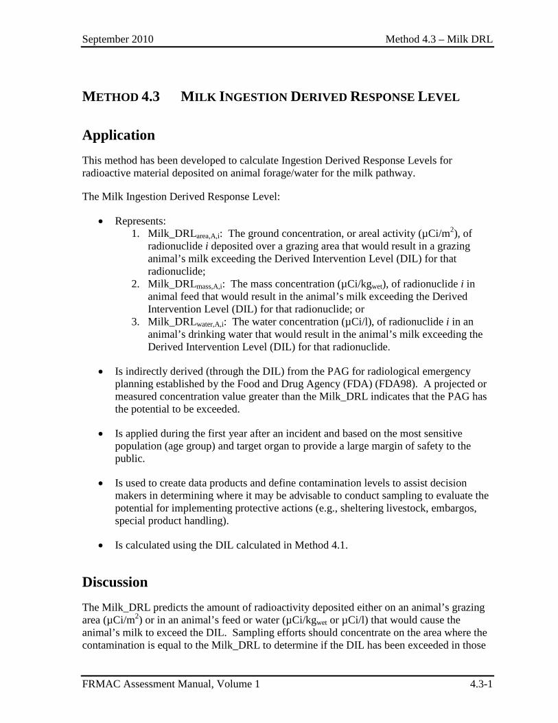
September 2010 Method 4.3 – Milk DRL
FRMAC Assessment Manual, Volume 1 4.3-1
METHOD 4.3 MILK INGESTION DERIVED RESPONSE LEVEL
Application This method has been developed to calculate Ingestion Derived Response Levels for radioactive material deposited on animal forage/water for the milk pathway.
The Milk Ingestion Derived Response Level:
• Represents: 1. Milk_DRLarea,A,i: The ground concentration, or areal activity (µCi/m2), of
radionuclide i deposited over a grazing area that would result in a grazing animal’s milk exceeding the Derived Intervention Level (DIL) for that radionuclide;
2. Milk_DRLmass,A,i: The mass concentration (µCi/kgwet), of radionuclide i in animal feed that would result in the animal’s milk exceeding the Derived Intervention Level (DIL) for that radionuclide; or
3. Milk_DRLwater,A,i: The water concentration (µCi/l), of radionuclide i in an animal’s drinking water that would result in the animal’s milk exceeding the Derived Intervention Level (DIL) for that radionuclide.
• Is indirectly derived (through the DIL) from the PAG for radiological emergency planning established by the Food and Drug Agency (FDA) (FDA98). A projected or measured concentration value greater than the Milk_DRL indicates that the PAG has the potential to be exceeded.
• Is applied during the first year after an incident and based on the most sensitive population (age group) and target organ to provide a large margin of safety to the public.
• Is used to create data products and define contamination levels to assist decision makers in determining where it may be advisable to conduct sampling to evaluate the potential for implementing protective actions (e.g., sheltering livestock, embargos, special product handling).
• Is calculated using the DIL calculated in Method 4.1.
Discussion The Milk_DRL predicts the amount of radioactivity deposited either on an animal’s grazing area (µCi/m2) or in an animal’s feed or water (µCi/kgwet or µCi/l) that would cause the animal’s milk to exceed the DIL. Sampling efforts should concentrate on the area where the contamination is equal to the Milk_DRL to determine if the DIL has been exceeded in those
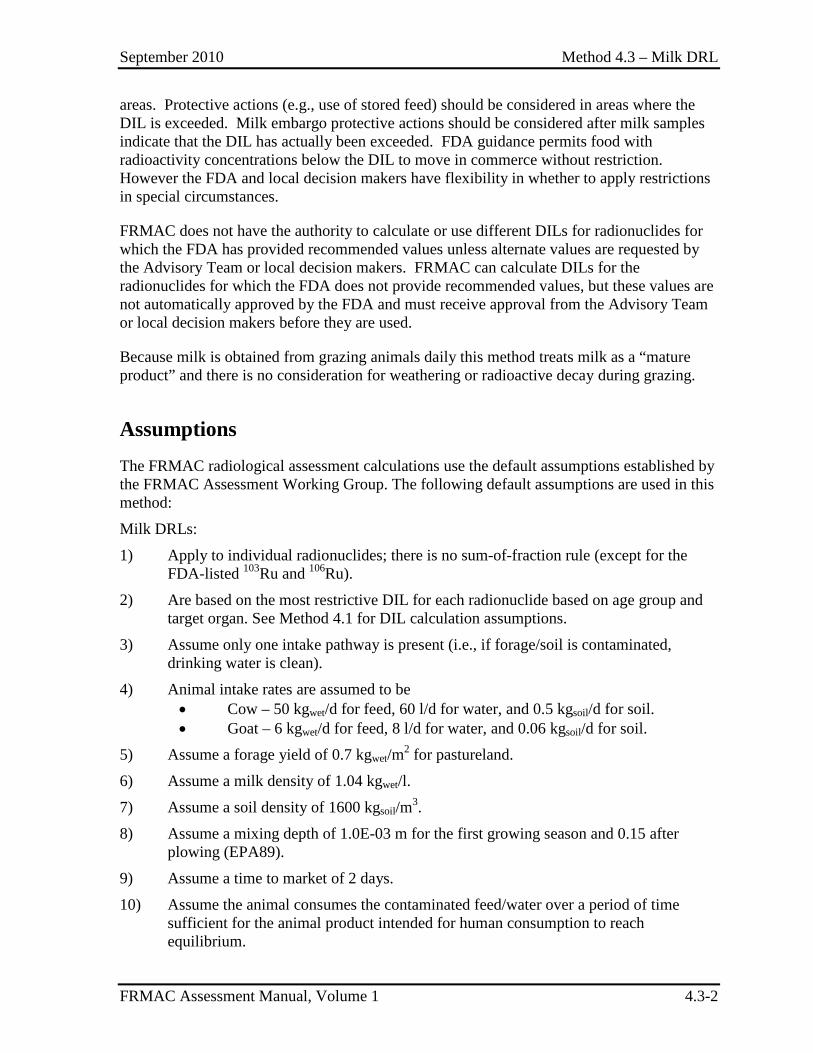
September 2010 Method 4.3 – Milk DRL
FRMAC Assessment Manual, Volume 1 4.3-2
areas. Protective actions (e.g., use of stored feed) should be considered in areas where the DIL is exceeded. Milk embargo protective actions should be considered after milk samples indicate that the DIL has actually been exceeded. FDA guidance permits food with radioactivity concentrations below the DIL to move in commerce without restriction. However the FDA and local decision makers have flexibility in whether to apply restrictions in special circumstances.
FRMAC does not have the authority to calculate or use different DILs for radionuclides for which the FDA has provided recommended values unless alternate values are requested by the Advisory Team or local decision makers. FRMAC can calculate DILs for the radionuclides for which the FDA does not provide recommended values, but these values are not automatically approved by the FDA and must receive approval from the Advisory Team or local decision makers before they are used.
Because milk is obtained from grazing animals daily this method treats milk as a “mature product” and there is no consideration for weathering or radioactive decay during grazing.
Assumptions The FRMAC radiological assessment calculations use the default assumptions established by the FRMAC Assessment Working Group. The following default assumptions are used in this method:
Milk DRLs:
1) Apply to individual radionuclides; there is no sum-of-fraction rule (except for the FDA-listed 103Ru and 106Ru).
2) Are based on the most restrictive DIL for each radionuclide based on age group and target organ. See Method 4.1 for DIL calculation assumptions.
3) Assume only one intake pathway is present (i.e., if forage/soil is contaminated, drinking water is clean).
4) Animal intake rates are assumed to be • Cow – 50 kgwet/d for feed, 60 l/d for water, and 0.5 kgsoil/d for soil. • Goat – 6 kgwet/d for feed, 8 l/d for water, and 0.06 kgsoil/d for soil.
5) Assume a forage yield of 0.7 kgwet/m2 for pastureland.
6) Assume a milk density of 1.04 kgwet/l.
7) Assume a soil density of 1600 kgsoil/m3.
8) Assume a mixing depth of 1.0E-03 m for the first growing season and 0.15 after plowing (EPA89).
9) Assume a time to market of 2 days.
10) Assume the animal consumes the contaminated feed/water over a period of time sufficient for the animal product intended for human consumption to reach equilibrium.
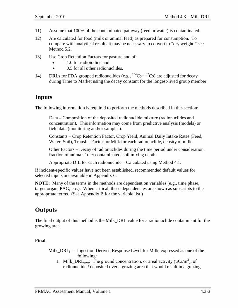
September 2010 Method 4.3 – Milk DRL
FRMAC Assessment Manual, Volume 1 4.3-3
11) Assume that 100% of the contaminated pathway (feed or water) is contaminated.
12) Are calculated for food (milk or animal feed) as prepared for consumption. To compare with analytical results it may be necessary to convert to “dry weight,” see Method 5.2.
13) Use Crop Retention Factors for pastureland of: • 1.0 for radioiodine and • 0.5 for all other radionuclides.
14) DRLs for FDA grouped radionuclides (e.g., 134Cs+137Cs) are adjusted for decay during Time to Market using the decay constant for the longest-lived group member.
Inputs The following information is required to perform the methods described in this section:
Data – Composition of the deposited radionuclide mixture (radionuclides and concentration). This information may come from predictive analysis (models) or field data (monitoring and/or samples).
Constants – Crop Retention Factor, Crop Yield, Animal Daily Intake Rates (Feed, Water, Soil), Transfer Factor for Milk for each radionuclide, density of milk.
Other Factors – Decay of radionuclides during the time period under consideration, fraction of animals’ diet contaminated, soil mixing depth.
Appropriate DIL for each radionuclide – Calculated using Method 4.1.
If incident-specific values have not been established, recommended default values for selected inputs are available in Appendix C.
NOTE: Many of the terms in the methods are dependent on variables (e.g., time phase, target organ, PAG, etc.). When critical, these dependencies are shown as subscripts to the appropriate terms. (See Appendix B for the variable list.)
Outputs The final output of this method is the Milk_DRL value for a radionuclide contaminant for the growing area.
Final
Milk_DRLi = Ingestion Derived Response Level for Milk, expressed as one of the following:
1. Milk_DRLarea: The ground concentration, or areal activity (µCi/m2), of radionuclide i deposited over a grazing area that would result in a grazing
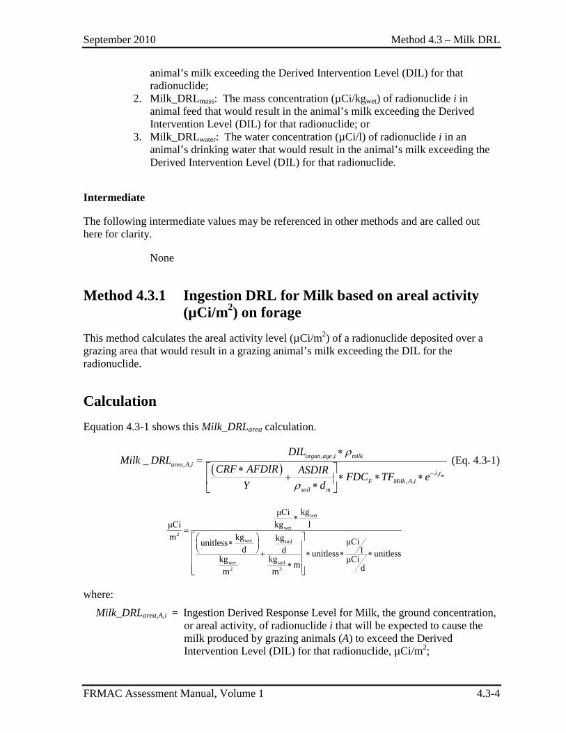
September 2010 Method 4.3 – Milk DRL
FRMAC Assessment Manual, Volume 1 4.3-4
animal’s milk exceeding the Derived Intervention Level (DIL) for that radionuclide;
2. Milk_DRLmass: The mass concentration (µCi/kgwet) of radionuclide i in animal feed that would result in the animal’s milk exceeding the Derived Intervention Level (DIL) for that radionuclide; or
3. Milk_DRLwater: The water concentration (µCi/l) of radionuclide i in an animal’s drinking water that would result in the animal’s milk exceeding the Derived Intervention Level (DIL) for that radionuclide.
Intermediate
The following intermediate values may be referenced in other methods and are called out here for clarity.
None
Method 4.3.1 Ingestion DRL for Milk based on areal activity (µCi/m2) on forage
This method calculates the areal activity level (µCi/m2) of a radionuclide deposited over a grazing area that would result in a grazing animal’s milk exceeding the DIL for the radionuclide.
Calculation Equation 4.3-1 shows this Milk_DRLarea calculation.
( )
, ,, ,
, ,
_i m
organ age i milkarea A i
tF Milk A i
soil m
DILMilk DRL
CRF AFDIR ASDIR FDC TF eY d
λ
ρ
ρ−
∗=
∗ + ∗ ∗ ∗ ∗
(Eq. 4.3-1)
wet
wet2
wet soil
wet soil2 3
kgμCikg lμCi
m kg kg μCiunitlessd d lunitless unitlesskg kg μCim dm m
∗= ∗ + ∗ ∗ ∗ ∗
where:
Milk_DRLarea,A,i = Ingestion Derived Response Level for Milk, the ground concentration, or areal activity, of radionuclide i that will be expected to cause the milk produced by grazing animals (A) to exceed the Derived Intervention Level (DIL) for that radionuclide, µCi/m2;
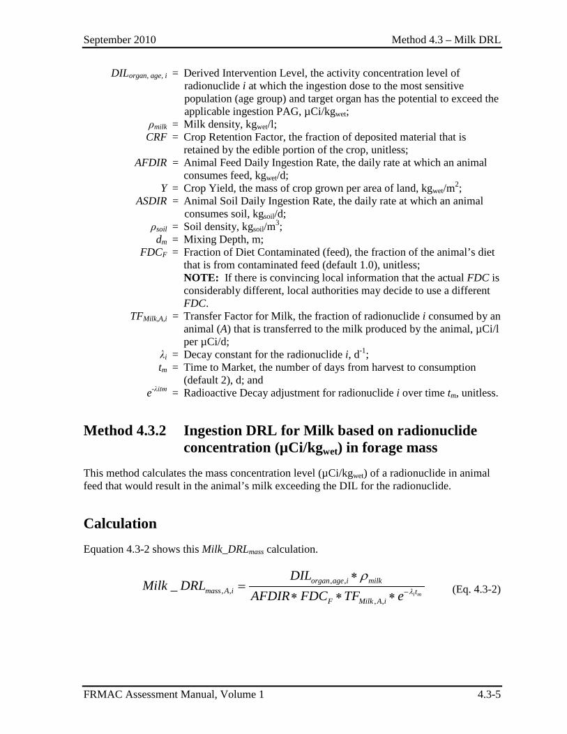
September 2010 Method 4.3 – Milk DRL
FRMAC Assessment Manual, Volume 1 4.3-5
DILorgan, age, i = Derived Intervention Level, the activity concentration level of radionuclide i at which the ingestion dose to the most sensitive population (age group) and target organ has the potential to exceed the applicable ingestion PAG, µCi/kgwet;
ρmilk = Milk density, kgwet/l; CRF = Crop Retention Factor, the fraction of deposited material that is
retained by the edible portion of the crop, unitless; AFDIR = Animal Feed Daily Ingestion Rate, the daily rate at which an animal
consumes feed, kgwet/d; Y = Crop Yield, the mass of crop grown per area of land, kgwet/m2; ASDIR = Animal Soil Daily Ingestion Rate, the daily rate at which an animal
consumes soil, kgsoil/d; ρsoil = Soil density, kgsoil/m3; dm = Mixing Depth, m; FDCF = Fraction of Diet Contaminated (feed), the fraction of the animal’s diet
that is from contaminated feed (default 1.0), unitless; NOTE: If there is convincing local information that the actual FDC is
considerably different, local authorities may decide to use a different FDC.
TFMilk,A,i = Transfer Factor for Milk, the fraction of radionuclide i consumed by an animal (A) that is transferred to the milk produced by the animal, µCi/l per µCi/d;
λi = Decay constant for the radionuclide i, d-1; tm = Time to Market, the number of days from harvest to consumption
(default 2), d; and e-λitm = Radioactive Decay adjustment for radionuclide i over time tm, unitless.
Method 4.3.2 Ingestion DRL for Milk based on radionuclide concentration (µCi/kgwet) in forage mass
This method calculates the mass concentration level (µCi/kgwet) of a radionuclide in animal feed that would result in the animal’s milk exceeding the DIL for the radionuclide.
Calculation Equation 4.3-2 shows this Milk_DRLmass calculation.
, ,
, ,, ,
_i m
organ age i milkmass A i t
F Milk A i
DILMilk DRL
AFDIR FDC TF e λ
ρ−
∗=
∗ ∗ ∗ (Eq. 4.3-2)
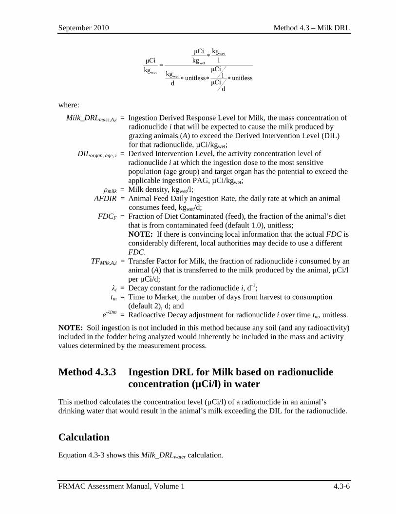
September 2010 Method 4.3 – Milk DRL
FRMAC Assessment Manual, Volume 1 4.3-6
wet
wet
wetwet
kgμCikg lμCi
μCikg kg lunitless unitlessμCidd
∗=
∗ ∗ ∗
where:
Milk_DRLmass,A,i = Ingestion Derived Response Level for Milk, the mass concentration of radionuclide i that will be expected to cause the milk produced by grazing animals (A) to exceed the Derived Intervention Level (DIL) for that radionuclide, µCi/kgwet;
DILorgan, age, i = Derived Intervention Level, the activity concentration level of radionuclide i at which the ingestion dose to the most sensitive population (age group) and target organ has the potential to exceed the applicable ingestion PAG, µCi/kgwet;
ρmilk = Milk density, kgwet/l; AFDIR = Animal Feed Daily Ingestion Rate, the daily rate at which an animal
consumes feed, kgwet/d; FDCF = Fraction of Diet Contaminated (feed), the fraction of the animal’s diet
that is from contaminated feed (default 1.0), unitless; NOTE: If there is convincing local information that the actual FDC is
considerably different, local authorities may decide to use a different FDC.
TFMilk,A,i = Transfer Factor for Milk, the fraction of radionuclide i consumed by an animal (A) that is transferred to the milk produced by the animal, µCi/l per µCi/d;
λi = Decay constant for the radionuclide i, d-1; tm = Time to Market, the number of days from harvest to consumption
(default 2), d; and e-λitm = Radioactive Decay adjustment for radionuclide i over time tm, unitless.
NOTE: Soil ingestion is not included in this method because any soil (and any radioactivity) included in the fodder being analyzed would inherently be included in the mass and activity values determined by the measurement process.
Method 4.3.3 Ingestion DRL for Milk based on radionuclide concentration (µCi/l) in water
This method calculates the concentration level (µCi/l) of a radionuclide in an animal’s drinking water that would result in the animal’s milk exceeding the DIL for the radionuclide.
Calculation Equation 4.3-3 shows this Milk_DRLwater calculation.
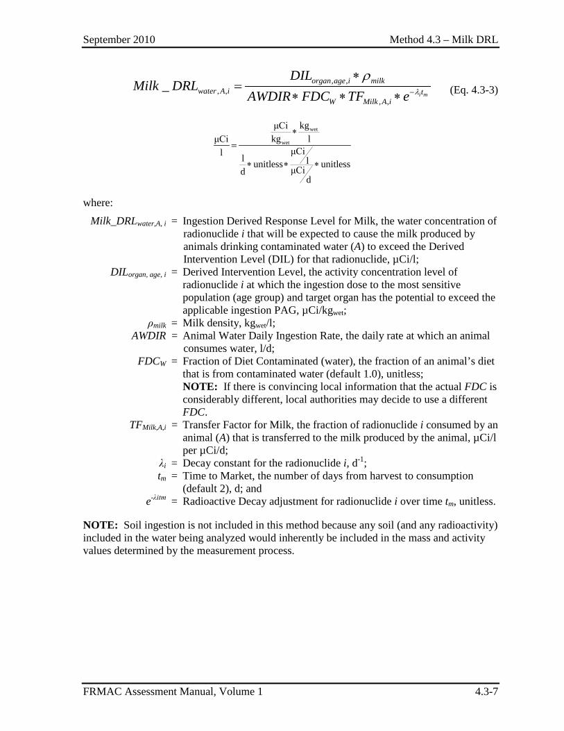
September 2010 Method 4.3 – Milk DRL
FRMAC Assessment Manual, Volume 1 4.3-7
, ,
, ,, ,
_i m
organ age i milkwater A i t
W Milk A i
DILMilk DRL
AWDIR FDC TF e λ
ρ−
∗=
∗ ∗ ∗ (Eq. 4.3-3)
wet
wet
kgμCikg lμCi
μCil l lunitless unitlessμCidd
∗=
∗ ∗ ∗
where:
Milk_DRLwater,A, i = Ingestion Derived Response Level for Milk, the water concentration of radionuclide i that will be expected to cause the milk produced by animals drinking contaminated water (A) to exceed the Derived Intervention Level (DIL) for that radionuclide, µCi/l;
DILorgan, age, i = Derived Intervention Level, the activity concentration level of radionuclide i at which the ingestion dose to the most sensitive population (age group) and target organ has the potential to exceed the applicable ingestion PAG, µCi/kgwet;
ρmilk = Milk density, kgwet/l; AWDIR = Animal Water Daily Ingestion Rate, the daily rate at which an animal
consumes water, l/d; FDCW = Fraction of Diet Contaminated (water), the fraction of an animal’s diet
that is from contaminated water (default 1.0), unitless; NOTE: If there is convincing local information that the actual FDC is
considerably different, local authorities may decide to use a different FDC.
TFMilk,A,i = Transfer Factor for Milk, the fraction of radionuclide i consumed by an animal (A) that is transferred to the milk produced by the animal, µCi/l per µCi/d;
λi = Decay constant for the radionuclide i, d-1; tm = Time to Market, the number of days from harvest to consumption
(default 2), d; and e-λitm = Radioactive Decay adjustment for radionuclide i over time tm, unitless.
NOTE: Soil ingestion is not included in this method because any soil (and any radioactivity) included in the water being analyzed would inherently be included in the mass and activity values determined by the measurement process.
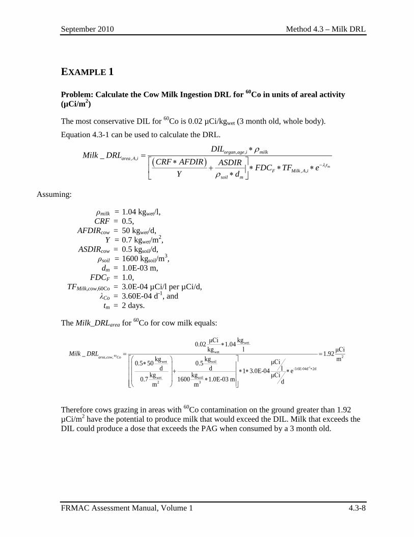
September 2010 Method 4.3 – Milk DRL
FRMAC Assessment Manual, Volume 1 4.3-8
EXAMPLE 1
Problem: Calculate the Cow Milk Ingestion DRL for 60Co in units of areal activity (µCi/m2)
The most conservative DIL for 60Co is 0.02 µCi/kgwet (3 month old, whole body).
Equation 4.3-1 can be used to calculate the DRL.
( )
, ,, ,
, ,
_i m
organ age i milkarea A i
tF Milk A i
soil m
DILMilk DRL
CRF AFDIR ASDIR FDC TF eY d
λ
ρ
ρ−
∗=
∗ + ∗ ∗ ∗ ∗
Assuming:
ρmilk = 1.04 kgwet/l, CRF = 0.5, AFDIRcow = 50 kgwet/d, Y = 0.7 kgwet/m2, ASDIRcow = 0.5 kgsoil/d, ρsoil = 1600 kgsoil/m3, dm = 1.0E-03 m, FDCF = 1.0, TFMilk,cow,60Co = 3.0E-04 µCi/l per µCi/d, λCo = 3.60E-04 d-1, and tm = 2 days.
The Milk_DRLarea for 60Co for cow milk equals:
60
-1
wet
wet2, ,
wet soil
-3.6E-04d 2d
wet soil2 3
kgμCi0.02 1.04kg l μCi_ 1.92
mkg kg μCi0.5 50 0.5d d l1 3.0E-04 ekg kg μCi0.7 1600 1.0E-03 m dm m
∗
∗= = ∗
+ ∗ ∗ ∗ ∗
area cow CoMilk DRL
Therefore cows grazing in areas with 60Co contamination on the ground greater than 1.92 µCi/m2 have the potential to produce milk that would exceed the DIL. Milk that exceeds the DIL could produce a dose that exceeds the PAG when consumed by a 3 month old.
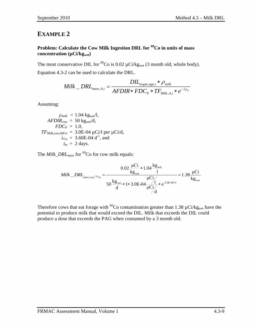
September 2010 Method 4.3 – Milk DRL
FRMAC Assessment Manual, Volume 1 4.3-9
EXAMPLE 2
Problem: Calculate the Cow Milk Ingestion DRL for 60Co in units of mass concentration (µCi/kgwet)
The most conservative DIL for 60Co is 0.02 µCi/kgwet (3 month old, whole body).
Equation 4.3-2 can be used to calculate the DRL.
, ,
, ,, ,
_i m
organ age i milkmass A i t
F Milk A i
DILMilk DRL
AFDIR FDC TF e λ
ρ−
∗=
∗ ∗ ∗
Assuming:
ρmilk = 1.04 kgwet/l, AFDIRcow = 50 kgwet/d, FDCF = 1.0, TFMilk,cow,60Co = 3.0E-04 µCi/l per µCi/d, λCo = 3.60E-04 d-1, and tm = 2 days.
The Milk_DRLmass for 60Co for cow milk equals:
60
wet
wet, ,
wet-3.6E-04 2wet
kgμCi0.02 1.04kg l μCi_ 1.38μCi kgkg l50 1 3.0E-04 eμCid
d
∗
∗= =
∗ ∗ ∗
mass cow CoMilk DRL
Therefore cows that eat forage with 60Co contamination greater than 1.38 µCi/kgwet have the potential to produce milk that would exceed the DIL. Milk that exceeds the DIL could produce a dose that exceeds the PAG when consumed by a 3 month old.
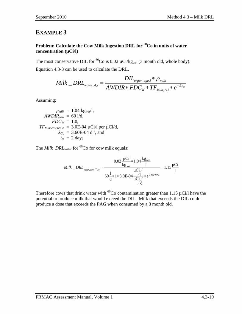
September 2010 Method 4.3 – Milk DRL
FRMAC Assessment Manual, Volume 1 4.3-10
EXAMPLE 3
Problem: Calculate the Cow Milk Ingestion DRL for 60Co in units of water concentration (µCi/l)
The most conservative DIL for 60Co is 0.02 µCi/kgwet (3 month old, whole body).
Equation 4.3-3 can be used to calculate the DRL.
, ,
, ,, ,
_i m
organ age i milkwater A i t
W Milk A i
DILMilk DRL
AWDIR FDC TF e λ
ρ−
∗=
∗ ∗ ∗
Assuming:
ρmilk = 1.04 kgwet/l, AWDIRcow = 60 l/d, FDCW = 1.0, TFMilk,cow,60Co = 3.0E-04 µCi/l per µCi/d, λCo = 3.60E-04 d-1, and tm = 2 days
The Milk_DRLwater for 60Co for cow milk equals:
60
wet
wet, ,
-3.6E-04 2
kgμCi0.02 1.04kg l μCi_ 1.15μCi ll l60 1 3.0E-04 eμCid
d
∗
∗= =
∗ ∗ ∗
water cow CoMilk DRL
Therefore cows that drink water with 60Co contamination greater than 1.15 µCi/l have the potential to produce milk that would exceed the DIL. Milk that exceeds the DIL could produce a dose that exceeds the PAG when consumed by a 3 month old.
September 2010 Method 4.4 – Meat DRL
FRMAC Assessment Manual, Volume 1 4.4-1
METHOD 4.4 MEAT INGESTION DERIVED RESPONSE LEVEL
Application This method has been developed to calculate Ingestion Derived Response Levels for radioactive material deposited on animal forage/water for the meat pathway.
The Meat Ingestion Derived Response Level:
• Represents: 1. Meat_DRLarea,A,i: The ground concentration, or areal activity (µCi/m2), of
radionuclide i deposited over a grazing area that would result in a grazing animal’s (A) meat exceeding the Derived Intervention Level (DIL) for that radionuclide;
2. Meat_DRLmass,A,i: The mass concentration (µCi/kgwet), of radionuclide i in animal feed that would result in the animal’s (A) meat exceeding the Derived Intervention Level (DIL) for that radionuclide; or
3. Meat_DRLwater,A,i: The water concentration (µCi/l), of radionuclide i in an animal’s drinking water that would result in the animal’s (A) meat exceeding the Derived Intervention Level (DIL) for that radionuclide.
• Is indirectly derived (through the DIL) from the PAG for radiological emergency planning established by the Food and Drug Agency (FDA) (FDA98). A projected or measured concentration value greater than the Meat_DRL indicates that the PAG has the potential to be exceeded.
• Is applied during the first year after an incident and based on the most sensitive population (age group) and target organ to provide a large margin of safety to the public.
• Is used to create data products and define contamination levels to assist decision makers in determining where it may be advisable to conduct sampling to evaluate the potential for implementing protective actions (e.g., sheltering livestock, embargos, special product handling).
• Is calculated using the DIL calculated in Method 4.1
Discussion The Meat_DRL predicts the amount of radioactivity deposited either on an animal’s grazing area (µCi/m2) or in an animal’s feed or water (µCi/kgwet or µCi/l) that would cause the animal’s meat to exceed the DIL.
September 2010 Method 4.4 – Meat DRL
FRMAC Assessment Manual, Volume 1 4.4-2
Sampling efforts should concentrate on the area where the contamination is equal to the Meat_DRL to determine if the DIL has been exceeded in those areas. Protective actions (e.g., use of stored feed) should be considered in areas where the DIL is exceeded. Meat embargo protective actions should be considered after meat samples indicate that the DIL has actually been exceeded. FDA guidance permits food with radioactivity concentrations below the DIL to move in commerce without restriction. However the FDA and local decision makers have flexibility in whether to apply restrictions in special circumstances.
FRMAC does not have the authority to calculate or use different DILs for radionuclides for which the FDA has provided recommended values unless alternate values are requested by the Advisory Team or local decision makers. FRMAC can calculate DILs for the radionuclides for which the FDA does not provide recommended values, but these values are not automatically approved by the FDA and must receive approval from the Advisory Team or local Decision Makers before they are used.
Assumptions The FRMAC radiological assessment calculations use the default assumptions established by the FRMAC Assessment Working Group. The following default assumptions are used in this method:
Meat DRLs:
1) Apply to individual radionuclides; there is no sum-of-fraction rule (except for the FDA-listed 103Ru and 106Ru).
2) Are based on the most restrictive DIL for each radionuclide based on age group and target organ. See Method 4.1 for DIL calculation assumptions.
3) Assume only one intake pathway is present (i.e., if forage/soil is contaminated, drinking water is clean).
4) Animal intake rates are assumed to be • Cow – 50 kgwet/d for feed, 60 l/d for water, and 0.5 kgsoil/d for soil. • Goat – 6 kgwet/d for feed, 8 l/d for water, and 0.06 kgsoil/d for soil.
5) Assume a forage yield of 0.7 kgwet/m2 for pastureland.
6) Assume a soil density of 1600 kgsoil/m3.
7) Assume a mixing depth of 1.0E-03 m for the first growing season and 0.15 after plowing (EPA89).
8) Assume a half life of 15 days for material weathering off plant material.
9) Assume a time to market of 20 days.
10) Assume the animal consumes the contaminated feed/water over a period of time sufficient for the animal product intended for human consumption to reach equilibrium.
11) Assume that 100% of the contaminated pathway (feed or water) is contaminated.
September 2010 Method 4.4 – Meat DRL
FRMAC Assessment Manual, Volume 1 4.4-3
12) Are calculated for food (meat or animal feed) as prepared for consumption. To compare with analytical results it may be necessary to convert to “dry weight,” see Method 5.2.
13) Uses Crop Retention Factors for pastureland of: • 1.0 for radioiodine and • 0.5 for all other radionuclides.
14) DRLs for FDA grouped radionuclides (e.g., 134Cs+137Cs) are adjusted for decay during Grazing Time and Time to Market using the decay constant for the longest-lived group member.
Inputs The following information is required to perform the methods described in this section:
Data – Composition of the deposited radionuclide mixture (radionuclides and concentration). This information may come from predictive analysis (models) or field data (monitoring and/or samples).
Constants – Crop Retention Factor, Crop Yield, Animal Daily Intake Rates (Feed, Water, Soil), Transfer Factor for each type of Meat and for each radionuclide.
Other Factors – Decay of radionuclides during the time period under consideration, fraction of animals’ diet contaminated, soil mixing depth.
Appropriate DIL for each radionuclide – Calculated using Method 4.1.
If incident-specific values have not been established, recommended default values for selected inputs are available in Appendix C. NOTE: Many of the terms in the methods are dependent on variables (e.g., time phase, target organ, PAG, etc.). When critical, these dependencies are shown as subscripts to the appropriate terms. (See Appendix B for the variable list.)
Outputs The final output of this method is the Meat_DRL value for a radionuclide contaminant for the growing area.
Final
Meat_DRLi = Ingestion Derived Response Level for Meat, expressed as one of the following:
1. Meat_DRLarea,A,i: The ground concentration, or areal activity (µCi/m2), of radionuclide i deposited over a grazing area that would result in a grazing animal’s (A) meat exceeding the Derived Intervention Level (DIL) for that radionuclide;
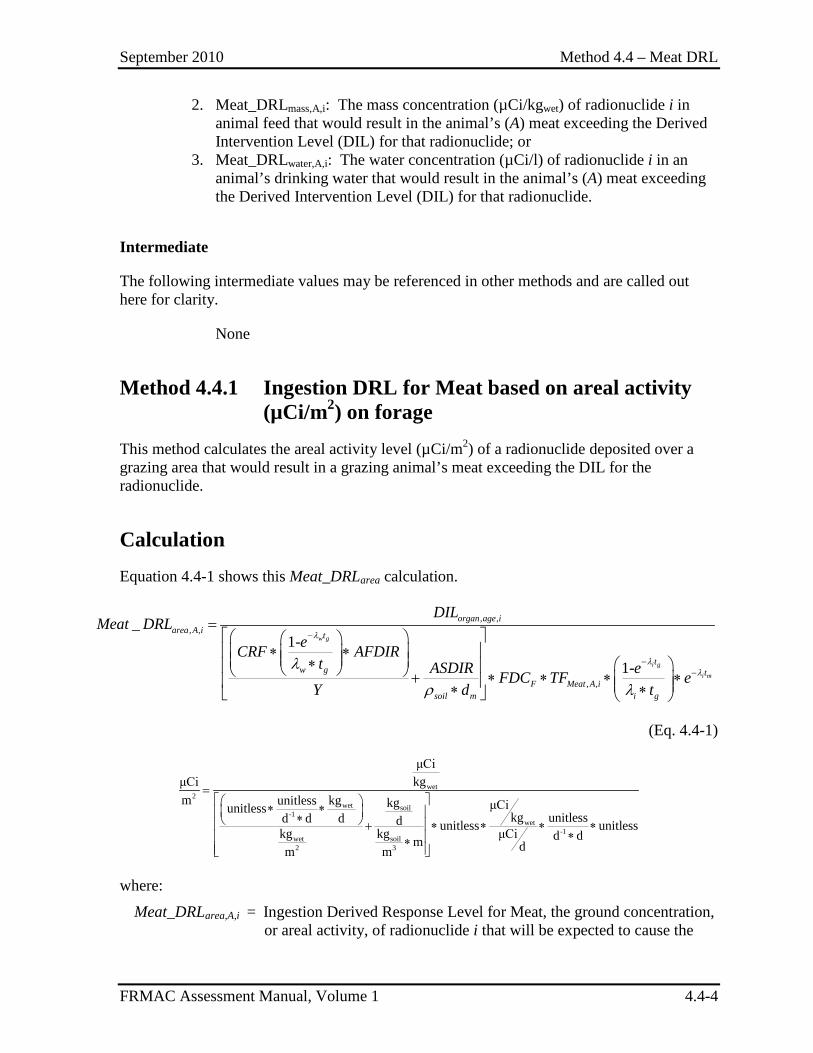
September 2010 Method 4.4 – Meat DRL
FRMAC Assessment Manual, Volume 1 4.4-4
2. Meat_DRLmass,A,i: The mass concentration (µCi/kgwet) of radionuclide i in animal feed that would result in the animal’s (A) meat exceeding the Derived Intervention Level (DIL) for that radionuclide; or
3. Meat_DRLwater,A,i: The water concentration (µCi/l) of radionuclide i in an animal’s drinking water that would result in the animal’s (A) meat exceeding the Derived Intervention Level (DIL) for that radionuclide.
Intermediate
The following intermediate values may be referenced in other methods and are called out here for clarity.
None
Method 4.4.1 Ingestion DRL for Meat based on areal activity (µCi/m2) on forage
This method calculates the areal activity level (µCi/m2) of a radionuclide deposited over a grazing area that would result in a grazing animal’s meat exceeding the DIL for the radionuclide.
Calculation Equation 4.4-1 shows this Meat_DRLarea calculation.
, ,, ,
, ,
_1-
1-
w g
i g
i m
organ age iarea A i t
tw g t
F Meat A isoil m i g
DILMeat DRL
eCRF AFDIRt ASDIR eFDC TF e
Y d t
λ
λλ
λ
ρ λ
−
−−
= ∗ ∗ ∗ + ∗ ∗ ∗ ∗ ∗ ∗
(Eq. 4.4-1)
wet
2wet soil
-1wet
-1wet soil2 3
μCikgμCi
m kgunitless kg μCiunitlesskg unitlessd d d d unitless unitlesskg kg μCi d dm dm m
= ∗ ∗ ∗ + ∗ ∗ ∗ ∗
∗ ∗
where:
Meat_DRLarea,A,i = Ingestion Derived Response Level for Meat, the ground concentration, or areal activity, of radionuclide i that will be expected to cause the
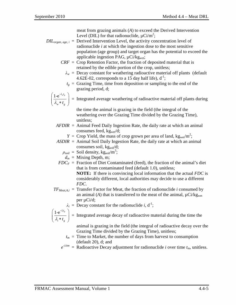
September 2010 Method 4.4 – Meat DRL
FRMAC Assessment Manual, Volume 1 4.4-5
meat from grazing animals (A) to exceed the Derived Intervention Level (DIL) for that radionuclide, µCi/m2;
DILorgan, age, i = Derived Intervention Level, the activity concentration level of radionuclide i at which the ingestion dose to the most sensitive population (age group) and target organ has the potential to exceed the applicable ingestion PAG, µCi/kgwet;
CRF = Crop Retention Factor, the fraction of deposited material that is retained by the edible portion of the crop, unitless;
λw = Decay constant for weathering radioactive material off plants (default 4.62E-02, corresponds to a 15 day half life), d-1;
tg = Grazing Time, time from deposition or sampling to the end of the grazing period, d;
-1-e w gt
w gt
λ
λ ∗
= Integrated average weathering of radioactive material off plants during
the time the animal is grazing in the field (the integral of the weathering over the Grazing Time divided by the Grazing Time), unitless;
AFDIR = Animal Feed Daily Ingestion Rate, the daily rate at which an animal consumes feed, kgwet/d;
Y = Crop Yield, the mass of crop grown per area of land, kgwet/m2; ASDIR = Animal Soil Daily Ingestion Rate, the daily rate at which an animal
consumes soil, kgsoil/d; ρsoil = Soil density, kgsoil/m3; dm = Mixing Depth, m; FDCF = Fraction of Diet Contaminated (feed), the fraction of the animal’s diet
that is from contaminated feed (default 1.0), unitless; NOTE: If there is convincing local information that the actual FDC is
considerably different, local authorities may decide to use a different FDC.
TFMeat,A,i = Transfer Factor for Meat, the fraction of radionuclide i consumed by an animal (A) that is transferred to the meat of the animal, µCi/kgwet per µCi/d;
λi = Decay constant for the radionuclide i, d-1;
-1-e i gt
i gt
λ
λ ∗
= Integrated average decay of radioactive material during the time the
animal is grazing in the field (the integral of radioactive decay over the Grazing Time divided by the Grazing Time), unitless;
tm = Time to Market, the number of days from harvest to consumption (default 20), d; and
e-λitm = Radioactive Decay adjustment for radionuclide i over time tm, unitless.
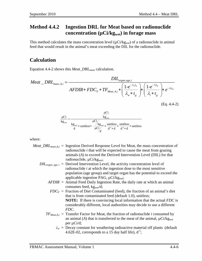
September 2010 Method 4.4 – Meat DRL
FRMAC Assessment Manual, Volume 1 4.4-6
Method 4.4.2 Ingestion DRL for Meat based on radionuclide concentration (µCi/kgwet) in forage mass
This method calculates the mass concentration level (µCi/kgwet) of a radionuclide in animal feed that would result in the animal’s meat exceeding the DIL for the radionuclide.
Calculation Equation 4.4-2 shows this Meat_DRLmass calculation.
, ,, ,
, ,
_1- 1-w g i g
i m
organ age imass A i t t
tF Meat A i
w g i g
DILMeat DRL
e eAFDIR FDC TF et t
λ λλ
λ λ
− −−
=
∗ ∗ ∗ ∗ ∗ ∗ ∗
(Eq. 4.4-2)
wet
wetwet wet
-1 -1
μCikgμCi
μCikgkg kg unitless unitlessunitless unitlessμCid d d d d
d
=
∗ ∗ ∗ ∗ ∗∗ ∗
where:
Meat_DRLmass,A,i = Ingestion Derived Response Level for Meat, the mass concentration of radionuclide i that will be expected to cause the meat from grazing animals (A) to exceed the Derived Intervention Level (DIL) for that radionuclide, µCi/kgwet;
DILorgan, age, i = Derived Intervention Level, the activity concentration level of radionuclide i at which the ingestion dose to the most sensitive population (age group) and target organ has the potential to exceed the applicable ingestion PAG, µCi/kgwet;
AFDIR = Animal Feed Daily Ingestion Rate, the daily rate at which an animal consumes feed, kgwet/d;
FDCF = Fraction of Diet Contaminated (feed), the fraction of an animal’s diet that is from contaminated feed (default 1.0), unitless;
NOTE: If there is convincing local information that the actual FDC is considerably different, local authorities may decide to use a different FDC.
TFMeat,A,i = Transfer Factor for Meat, the fraction of radionuclide i consumed by an animal (A) that is transferred to the meat of the animal, µCi/kgwet per µCi/d;
λw = Decay constant for weathering radioactive material off plants (default 4.62E-02, corresponds to a 15 day half life), d-1;
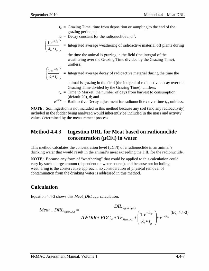
September 2010 Method 4.4 – Meat DRL
FRMAC Assessment Manual, Volume 1 4.4-7
tg = Grazing Time, time from deposition or sampling to the end of the grazing period, d;
λi = Decay constant for the radionuclide i, d-1;
-1-e w gt
w gt
λ
λ ∗
= Integrated average weathering of radioactive material off plants during
the time the animal is grazing in the field (the integral of the weathering over the Grazing Time divided by the Grazing Time), unitless;
-1-e i gt
i gt
λ
λ ∗
= Integrated average decay of radioactive material during the time the
animal is grazing in the field (the integral of radioactive decay over the Grazing Time divided by the Grazing Time), unitless;
tm = Time to Market, the number of days from harvest to consumption (default 20), d; and
e-λitm = Radioactive Decay adjustment for radionuclide i over time tm, unitless.
NOTE: Soil ingestion is not included in this method because any soil (and any radioactivity) included in the fodder being analyzed would inherently be included in the mass and activity values determined by the measurement process.
Method 4.4.3 Ingestion DRL for Meat based on radionuclide concentration (µCi/l) in water
This method calculates the concentration level (µCi/l) of a radionuclide in an animal’s drinking water that would result in the animal’s meat exceeding the DIL for the radionuclide.
NOTE: Because any form of “weathering” that could be applied to this calculation could vary by such a large amount (dependent on water source), and because not including weathering is the conservative approach, no consideration of physical removal of contamination from the drinking water is addressed in this method.
Calculation Equation 4.4-3 shows this Meat_DRLwater calculation.
, ,
, ,
, ,
_1- i g
i m
organ age iwater A i t
tW Meat A i
i g
DILMeat DRL
eAWDIR FDC TF et
λλ
λ
−−
=
∗ ∗ ∗ ∗ ∗
(Eq. 4.4-3)
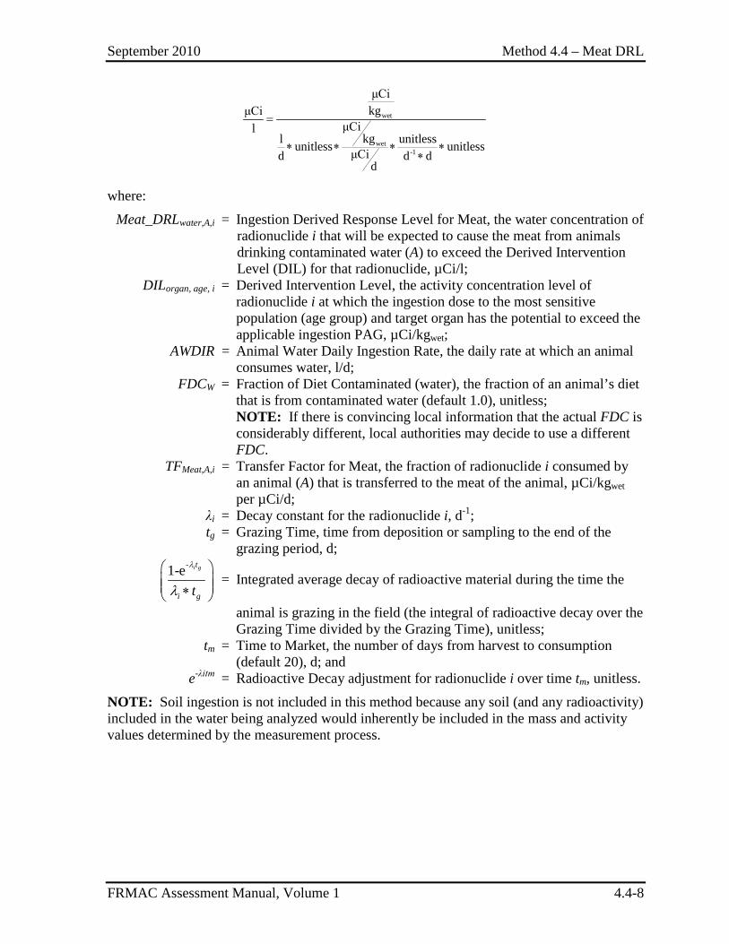
September 2010 Method 4.4 – Meat DRL
FRMAC Assessment Manual, Volume 1 4.4-8
wet
wet-1
μCikgμCi
μCilkgl unitlessunitless unitlessμCid d d
d
=
∗ ∗ ∗ ∗∗
where:
Meat_DRLwater,A,i = Ingestion Derived Response Level for Meat, the water concentration of radionuclide i that will be expected to cause the meat from animals drinking contaminated water (A) to exceed the Derived Intervention Level (DIL) for that radionuclide, µCi/l;
DILorgan, age, i = Derived Intervention Level, the activity concentration level of radionuclide i at which the ingestion dose to the most sensitive population (age group) and target organ has the potential to exceed the applicable ingestion PAG, µCi/kgwet;
AWDIR = Animal Water Daily Ingestion Rate, the daily rate at which an animal consumes water, l/d;
FDCW = Fraction of Diet Contaminated (water), the fraction of an animal’s diet that is from contaminated water (default 1.0), unitless;
NOTE: If there is convincing local information that the actual FDC is considerably different, local authorities may decide to use a different FDC.
TFMeat,A,i = Transfer Factor for Meat, the fraction of radionuclide i consumed by an animal (A) that is transferred to the meat of the animal, µCi/kgwet per µCi/d;
λi = Decay constant for the radionuclide i, d-1; tg = Grazing Time, time from deposition or sampling to the end of the
grazing period, d;
-1-e i gt
i gt
λ
λ ∗
= Integrated average decay of radioactive material during the time the
animal is grazing in the field (the integral of radioactive decay over the Grazing Time divided by the Grazing Time), unitless;
tm = Time to Market, the number of days from harvest to consumption (default 20), d; and
e-λitm = Radioactive Decay adjustment for radionuclide i over time tm, unitless.
NOTE: Soil ingestion is not included in this method because any soil (and any radioactivity) included in the water being analyzed would inherently be included in the mass and activity values determined by the measurement process.
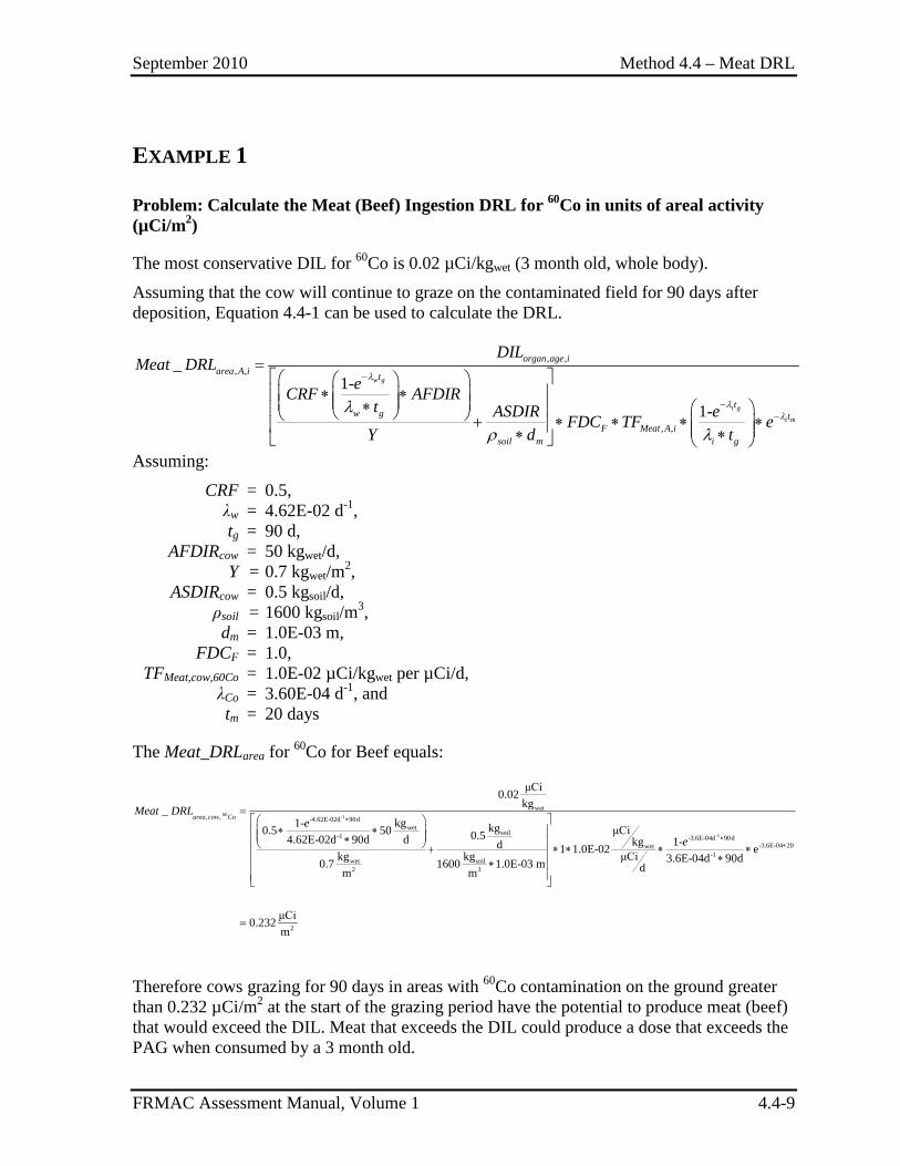
September 2010 Method 4.4 – Meat DRL
FRMAC Assessment Manual, Volume 1 4.4-9
EXAMPLE 1
Problem: Calculate the Meat (Beef) Ingestion DRL for 60Co in units of areal activity (µCi/m2)
The most conservative DIL for 60Co is 0.02 µCi/kgwet (3 month old, whole body).
Assuming that the cow will continue to graze on the contaminated field for 90 days after deposition, Equation 4.4-1 can be used to calculate the DRL.
, ,, ,
, ,
_1-
1-
w g
i g
i m
organ age iarea A i t
tw g t
F Meat A isoil m i g
DILMeat DRL
eCRF AFDIRt ASDIR eFDC TF e
Y d t
λ
λλ
λ
ρ λ
−
−−
= ∗ ∗ ∗ + ∗ ∗ ∗ ∗ ∗ ∗
Assuming:
CRF = 0.5, λw = 4.62E-02 d-1, tg = 90 d, AFDIRcow = 50 kgwet/d, Y = 0.7 kgwet/m2, ASDIRcow = 0.5 kgsoil/d, ρsoil = 1600 kgsoil/m3, dm = 1.0E-03 m, FDCF = 1.0, TFMeat,cow,60Co = 1.0E-02 µCi/kgwet per µCi/d, λCo = 3.60E-04 d-1, and tm = 20 days
The Meat_DRLarea for 60Co for Beef equals:
60 -1
-1
wet, , -4.62E-02d 90d
wetsoil-1 -3.6E-04d 90d
wet-1
wet soil2 3
μCi0.02kg_
1- kg kg μCi0.5 50 0.54.62E-02d 90d d 1-kgd 1 1.0E-02kg kg μCi 3.6E-04d 900.7 1600 1.0E-03 m dm m
area cow CoMeat DRL
ee
∗
∗
=
∗ ∗ ∗ + ∗ ∗ ∗ ∗∗
-3.6E-04 20
2
ed
μCi0.232m
∗∗
=
Therefore cows grazing for 90 days in areas with 60Co contamination on the ground greater than 0.232 µCi/m2 at the start of the grazing period have the potential to produce meat (beef) that would exceed the DIL. Meat that exceeds the DIL could produce a dose that exceeds the PAG when consumed by a 3 month old.
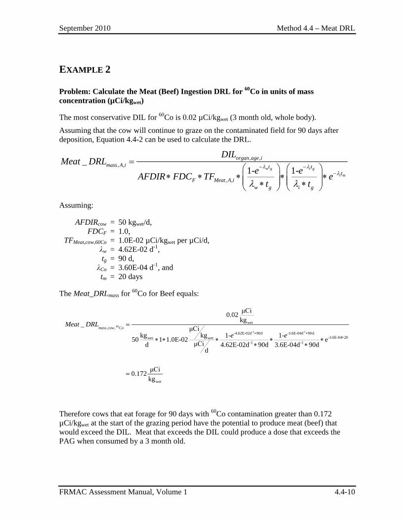
September 2010 Method 4.4 – Meat DRL
FRMAC Assessment Manual, Volume 1 4.4-10
EXAMPLE 2
Problem: Calculate the Meat (Beef) Ingestion DRL for 60Co in units of mass concentration (µCi/kgwet)
The most conservative DIL for 60Co is 0.02 µCi/kgwet (3 month old, whole body).
Assuming that the cow will continue to graze on the contaminated field for 90 days after deposition, Equation 4.4-2 can be used to calculate the DRL.
, ,, ,
, ,
_1- 1-w g i g
i m
organ age imass A i t t
tF Meat A i
w g i g
DILMeat DRL
e eAFDIR FDC TF et t
λ λλ
λ λ
− −−
=
∗ ∗ ∗ ∗ ∗ ∗ ∗
Assuming:
AFDIRcow = 50 kgwet/d, FDCF = 1.0, TFMeat,cow,60Co = 1.0E-02 µCi/kgwet per µCi/d, λw = 4.62E-02 d-1, tg = 90 d, λCo = 3.60E-04 d-1, and tm = 20 days
The Meat_DRLmass for 60Co for Beef equals:
60
-1 -1
wet, ,
-4.62E-02d 90d -3.6E-04d 90d-3.6E-04 20wet wet
-1 -1
wet
μCi0.02kg_ μCi
kg kg 1- 1-50 1 1.0E-02 eμCid 4.62E-02d 90d 3.6E-04d 90dd
μCi0.172kg
mass cow CoMeat DRL
e e∗ ∗∗
=
∗ ∗ ∗ ∗ ∗∗ ∗
=
Therefore cows that eat forage for 90 days with 60Co contamination greater than 0.172 µCi/kgwet at the start of the grazing period have the potential to produce meat (beef) that would exceed the DIL. Meat that exceeds the DIL could produce a dose that exceeds the PAG when consumed by a 3 month old.
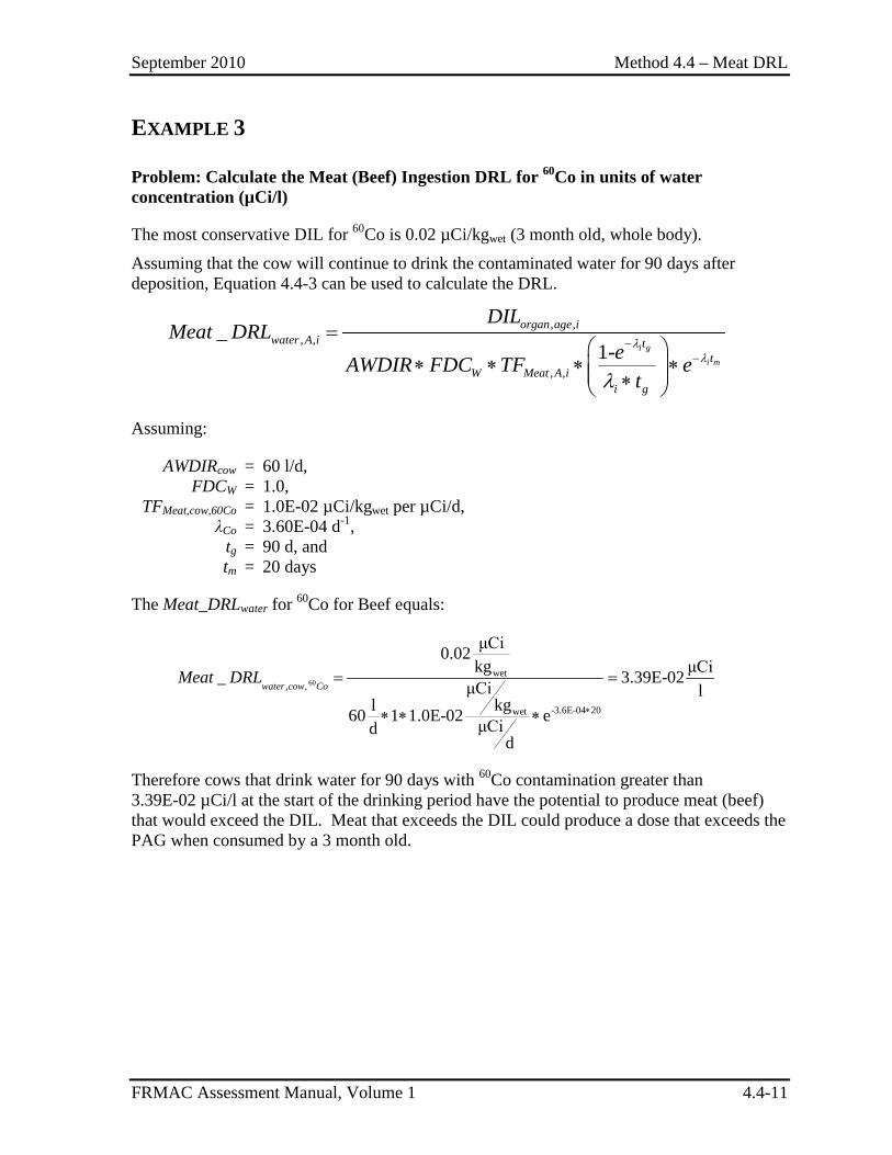
September 2010 Method 4.4 – Meat DRL
FRMAC Assessment Manual, Volume 1 4.4-11
EXAMPLE 3
Problem: Calculate the Meat (Beef) Ingestion DRL for 60Co in units of water concentration (µCi/l)
The most conservative DIL for 60Co is 0.02 µCi/kgwet (3 month old, whole body).
Assuming that the cow will continue to drink the contaminated water for 90 days after deposition, Equation 4.4-3 can be used to calculate the DRL.
, ,
, ,
, ,
_1- i g
i m
organ age iwater A i t
tW Meat A i
i g
DILMeat DRL
eAWDIR FDC TF et
λλ
λ
−−
=
∗ ∗ ∗ ∗ ∗
Assuming:
AWDIRcow = 60 l/d, FDCW = 1.0, TFMeat,cow,60Co = 1.0E-02 µCi/kgwet per µCi/d, λCo = 3.60E-04 d-1, tg = 90 d, and tm = 20 days
The Meat_DRLwater for 60Co for Beef equals:
60wet
, ,
-3.6E-04 20wet
μCi0.02kg μCi_ 3.39E-02μCi l
kgl60 1 1.0E-02 eμCidd
water cow CoMeat DRL
∗
= =
∗ ∗ ∗
Therefore cows that drink water for 90 days with 60Co contamination greater than 3.39E-02 µCi/l at the start of the drinking period have the potential to produce meat (beef) that would exceed the DIL. Meat that exceeds the DIL could produce a dose that exceeds the PAG when consumed by a 3 month old.
September 2010 Method 4.4 – Meat DRL
FRMAC Assessment Manual, Volume 1 4.4-12
This page intentionally left blank.
September 2010 Method 4.5 – Ingestion Dose
FRMAC Assessment Manual, Volume 1 4.5-1
METHOD 4.5 INGESTION DOSE
Application This method has been developed to calculate the Ingestion Dose from the consumption of radioactive material, either in food, milk or water.
The Ingestion Dose:
• Can be applied to the whole body (E50) or to a specific organ (HT,50)
• Uses sample results for various food types to calculate the dose that a receptor is projected to receive over a specified time phase (generally 1 year) due to ingestion of the contaminated food.
• Is used to define dose levels to assist decision makers in determining where it may be advisable to implement protective actions (e.g. sheltering livestock, embargos, special product handling).
Discussion The Ingestion Dose method calculates the expected dose from consuming foods contaminated by radioactive material and is obtained by combining sample results (µCi/kg or µCi/l) for various food types to produce a total projected dose from the entire diet. Food types generally fall into 4 groups (shown with subgroups):
• Meat/Fish (Beef, Pork, Poultry, Fin Fish, Shell Fish, Other Meat); • Crop/Produce (Leafy, Exposed, Protected, Other Produce, Breads, Cereals, Other
Grains); • Milk (Fresh Cow’s Milk, Other Dairy, Eggs); and • Beverages (Tap Water, Water Based Drinks, Soups, Other Beverages).
Assumptions The FRMAC radiological assessment calculations use the default assumptions established by the FRMAC Assessment Working Group. The following default assumptions are used in this method:
1) Annual intake for each group and subgroup of foods varies by age group (3 month, 1 yr, 5 yr, 10 yr, 15 yr and adult) (FDA98). If specific intake rates are known, use those instead of defaults.
September 2010 Method 4.5 – Ingestion Dose
FRMAC Assessment Manual, Volume 1 4.5-2
2) Dose calculations are based on samples of foods as prepared for consumption and assume a consumption period of 1 year. To compare with analytical results it may be necessary to convert to “dry weight,” see Method 5.2.
3) Inadvertent ingestion of soil is not included in these methods. Activity contained in any soil present in the food would be accounted for in the sample analysis process. Inadvertent Soil Ingestion is discussed in Method 4.7.
4) Default calculations utilize the International Commission on Radiological Protection (ICRP) 60+ dosimetry model.
Inputs The following information is required to perform the methods described in this section:
• Data – Activity concentration (µCi/kg or µCi/l) from sample analysis data.
• Constants – Fraction of food contaminated, daily food intake rate, ingestion dose coefficient.
• Other Factors – Decay of radionuclides from sampling time to consumption time (hold time) and over the duration of consumption (default consumption period is 1 year).
If incident-specific values have not been established, recommended default values for selected inputs are available in Appendix C.
NOTE: Many of the terms in the methods are dependent on variables (e.g., time phase, target organ, PAG, etc.). When critical, these dependencies are shown as subscripts to the appropriate terms. (See Appendix B for the variable list.)
Outputs The final output of this method is the Ingestion Dose for a diet including food sources that have been contaminated by a deposition of radioactive material.
Final
E50 = Committed Effective Dose, the dose to the whole body, received by the receptor under consideration over the commitment period, from the ingestion of all radionuclides in contaminated food, mrem
HT,50 = Committed Equivalent Dose, the dose to organ “t”, received by the receptor under consideration over the commitment period, from the ingestion of all radionuclides in contaminated food, mrem
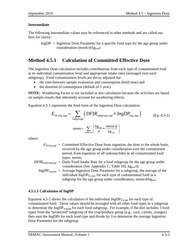
September 2010 Method 4.5 – Ingestion Dose
FRMAC Assessment Manual, Volume 1 4.5-3
Intermediate
The following intermediate values may be referenced in other methods and are called out here for clarity.
IngDP = Ingestion Dose Parameter for a specific food type for the age group under consideration (mrem·d/kgwet)
Method 4.5.1 Calculation of Committed Effective Dose The Ingestion Dose calculation includes contributions from each type of contaminated food at its individual contamination level and appropriate intake rates (averaged over each subgroup). Food contamination levels are decay adjusted for:
• the time between sample evaluation and consumption (hold time) and • the duration of consumption (default of 1 year).
NOTE: Weathering Factor is not included in this calculation because the activities are based on sample results that inherently account for weathering effects.
Equation 4.5-1 represents the final form of the Ingestion Dose calculation:
( )50, , , ,Ing age subgroup age avg ageSubgroup
E DFIR IngDP= ∗∑ (Eq. 4.5-1)
wet
wet
kg mrem dmremd kgSubgroup
= ∗
∑
where:
E50,Ing,age = Committed Effective Dose from ingestion, the dose to the whole body, received by the age group under consideration over the commitment period, from ingestion of all radionuclides in all contaminated food types, mrem;
DFIRsubgroup,age = Daily Food Intake Rate for a food subgroup for the age group under consideration (See Appendix C, Table 10), kgwet/d;
IngDPavg,age = Average Ingestion Dose Parameter for a subgroup, the average of the individual IngDPE,f,age for each type of contaminated food in a subgroup for the age group under consideration, mrem·d/kgwet.
4.5.1.1 Calculation of IngDP
Equation 4.5-2 shows the calculation of the individual IngDPE,f,age for each type of contaminated food. These values should be averaged with all other food types in a subgroup to determine the IngDPavg,age for each food subgroup. For example, if the diet includes 3 food types from the “protected” subgroup of the crop/produce group (e.g., corn, carrots, oranges) then sum the IngDPs for each food type and divide by 3 to determine the average Ingestion Dose Parameter for the subgroup.
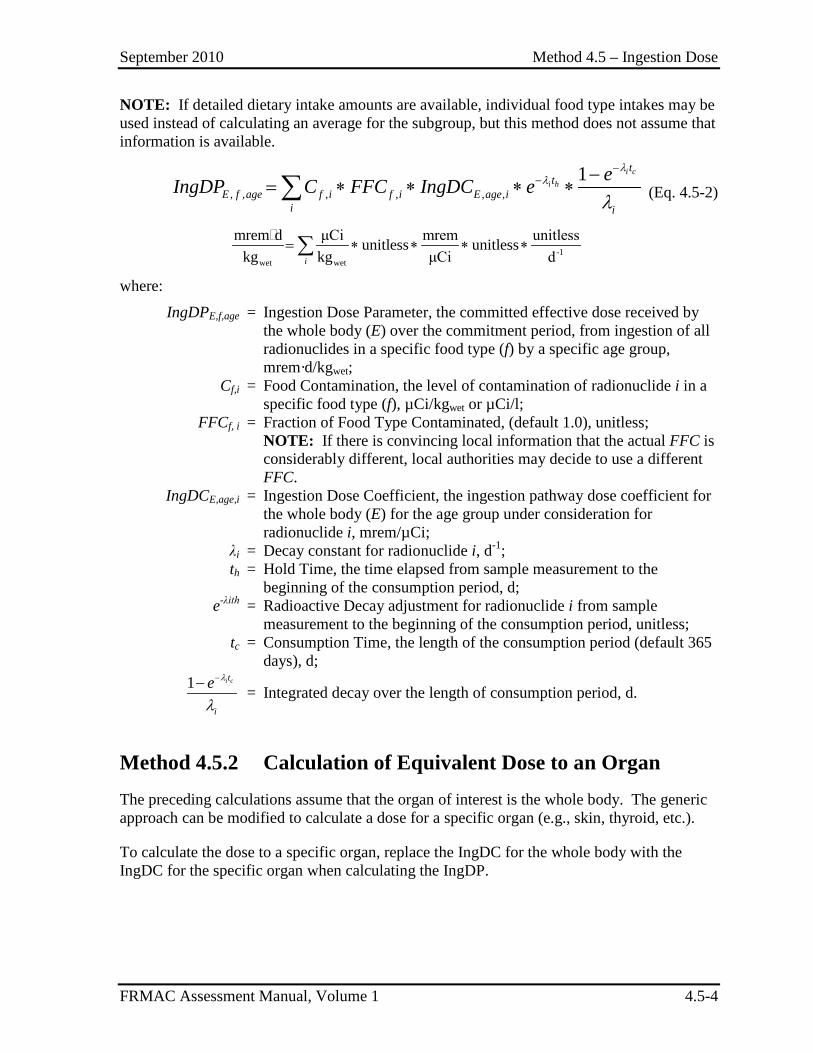
September 2010 Method 4.5 – Ingestion Dose
FRMAC Assessment Manual, Volume 1 4.5-4
NOTE: If detailed dietary intake amounts are available, individual food type intakes may be used instead of calculating an average for the subgroup, but this method does not assume that information is available.
, , , , , ,1 i c
i h
tt
E f age f i f i E age ii i
eIngDP C FFC IngDC eλ
λ
λ
−− −
= ∗ ∗ ∗ ∗∑ (Eq. 4.5-2)
-1
wet wet
mrem d μCi mrem unitlessunitless unitlesskg kg μCi di
= ∗ ∗ ∗ ∗∑
where:
IngDPE,f,age = Ingestion Dose Parameter, the committed effective dose received by the whole body (E) over the commitment period, from ingestion of all radionuclides in a specific food type (f) by a specific age group, mrem·d/kgwet;
Cf,i = Food Contamination, the level of contamination of radionuclide i in a specific food type (f), µCi/kgwet or µCi/l;
FFCf, i = Fraction of Food Type Contaminated, (default 1.0), unitless; NOTE: If there is convincing local information that the actual FFC is
considerably different, local authorities may decide to use a different FFC.
IngDCE,age,i = Ingestion Dose Coefficient, the ingestion pathway dose coefficient for the whole body (E) for the age group under consideration for radionuclide i, mrem/µCi;
λi = Decay constant for radionuclide i, d-1; th = Hold Time, the time elapsed from sample measurement to the
beginning of the consumption period, d; e-λith = Radioactive Decay adjustment for radionuclide i from sample
measurement to the beginning of the consumption period, unitless; tc = Consumption Time, the length of the consumption period (default 365
days), d;
1 i ct
i
e λ
λ
−− = Integrated decay over the length of consumption period, d.
Method 4.5.2 Calculation of Equivalent Dose to an Organ The preceding calculations assume that the organ of interest is the whole body. The generic approach can be modified to calculate a dose for a specific organ (e.g., skin, thyroid, etc.).
To calculate the dose to a specific organ, replace the IngDC for the whole body with the IngDC for the specific organ when calculating the IngDP.
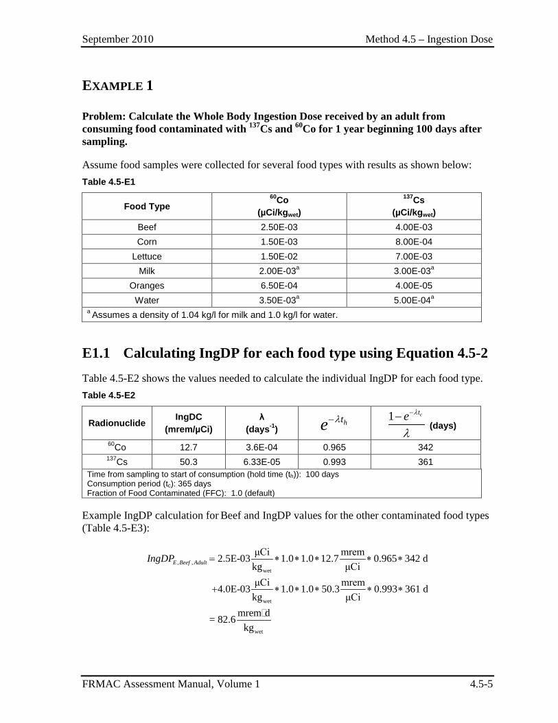
September 2010 Method 4.5 – Ingestion Dose
FRMAC Assessment Manual, Volume 1 4.5-5
EXAMPLE 1
Problem: Calculate the Whole Body Ingestion Dose received by an adult from consuming food contaminated with 137Cs and 60Co for 1 year beginning 100 days after sampling.
Assume food samples were collected for several food types with results as shown below: Table 4.5-E1
Food Type 60Co
(µCi/kgwet)
137Cs (µCi/kgwet)
Beef 2.50E-03 4.00E-03 Corn 1.50E-03 8.00E-04
Lettuce 1.50E-02 7.00E-03 Milk 2.00E-03a 3.00E-03a
Oranges 6.50E-04 4.00E-05 Water 3.50E-03a 5.00E-04a
a Assumes a density of 1.04 kg/l for milk and 1.0 kg/l for water.
E1.1 Calculating IngDP for each food type using Equation 4.5-2 Table 4.5-E2 shows the values needed to calculate the individual IngDP for each food type. Table 4.5-E2
Radionuclide IngDC (mrem/µCi)
λ (days-1)
hte λ−
1 cte λ
λ
−− (days)
60Co 12.7 3.6E-04 0.965 342 137Cs 50.3 6.33E-05 0.993 361
Time from sampling to start of consumption (hold time (th)): 100 days Consumption period (tc): 365 days Fraction of Food Contaminated (FFC): 1.0 (default)
Example IngDP calculation for Beef and IngDP values for the other contaminated food types (Table 4.5-E3):
, ,wet
wet
wet
μCi mrem2.5E-03 1.0 1.0 12.7 0.965 342 dkg μCiμCi mrem4.0E-03 1.0 1.0 50.3 0.993 361 dkg μCi
mrem d= 82.6kg
E Beef AdultIngDP = ∗ ∗ ∗ ∗ ∗
+ ∗ ∗ ∗ ∗ ∗
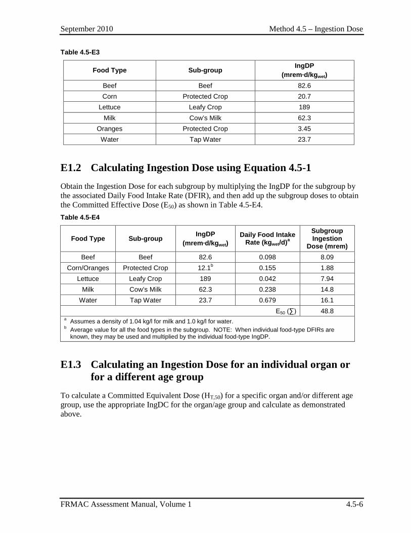
September 2010 Method 4.5 – Ingestion Dose
FRMAC Assessment Manual, Volume 1 4.5-6
Table 4.5-E3
Food Type Sub-group IngDP (mrem·d/kgwet)
Beef Beef 82.6 Corn Protected Crop 20.7
Lettuce Leafy Crop 189 Milk Cow’s Milk 62.3
Oranges Protected Crop 3.45 Water Tap Water 23.7
E1.2 Calculating Ingestion Dose using Equation 4.5-1 Obtain the Ingestion Dose for each subgroup by multiplying the IngDP for the subgroup by the associated Daily Food Intake Rate (DFIR), and then add up the subgroup doses to obtain the Committed Effective Dose (E50) as shown in Table 4.5-E4. Table 4.5-E4
Food Type Sub-group IngDP (mrem·d/kgwet)
Daily Food Intake Rate (kgwet/d)a
Subgroup Ingestion
Dose (mrem) Beef Beef 82.6 0.098 8.09
Corn/Oranges Protected Crop 12.1b 0.155 1.88 Lettuce Leafy Crop 189 0.042 7.94
Milk Cow’s Milk 62.3 0.238 14.8 Water Tap Water 23.7 0.679 16.1
E50 (∑) 48.8 a Assumes a density of 1.04 kg/l for milk and 1.0 kg/l for water. b Average value for all the food types in the subgroup. NOTE: When individual food-type DFIRs are
known, they may be used and multiplied by the individual food-type IngDP.
E1.3 Calculating an Ingestion Dose for an individual organ or for a different age group
To calculate a Committed Equivalent Dose (HT,50) for a specific organ and/or different age group, use the appropriate IngDC for the organ/age group and calculate as demonstrated above.
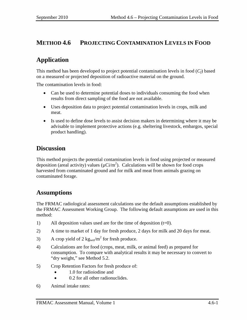
September 2010 Method 4.6 – Projecting Contamination Levels in Food
FRMAC Assessment Manual, Volume 1 4.6-1
METHOD 4.6 PROJECTING CONTAMINATION LEVELS IN FOOD
Application This method has been developed to project potential contamination levels in food (Cf) based on a measured or projected deposition of radioactive material on the ground.
The contamination levels in food:
• Can be used to determine potential doses to individuals consuming the food when results from direct sampling of the food are not available.
• Uses deposition data to project potential contamination levels in crops, milk and meat.
• Is used to define dose levels to assist decision makers in determining where it may be advisable to implement protective actions (e.g. sheltering livestock, embargos, special product handling).
Discussion This method projects the potential contamination levels in food using projected or measured deposition (areal activity) values (µCi/m2). Calculations will be shown for food crops harvested from contaminated ground and for milk and meat from animals grazing on contaminated forage.
Assumptions The FRMAC radiological assessment calculations use the default assumptions established by the FRMAC Assessment Working Group. The following default assumptions are used in this method:
1) All deposition values used are for the time of deposition (t=0).
2) A time to market of 1 day for fresh produce, 2 days for milk and 20 days for meat.
3) A crop yield of 2 kgwet/m2 for fresh produce.
4) Calculations are for food (crops, meat, milk, or animal feed) as prepared for consumption. To compare with analytical results it may be necessary to convert to “dry weight,” see Method 5.2.
5) Crop Retention Factors for fresh produce of: • 1.0 for radioiodine and • 0.2 for all other radionuclides.
6) Animal intake rates:
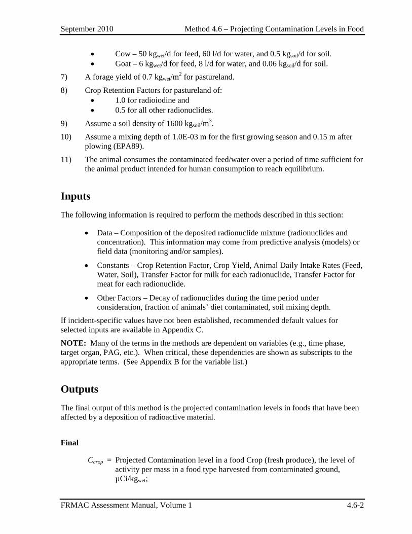
September 2010 Method 4.6 – Projecting Contamination Levels in Food
FRMAC Assessment Manual, Volume 1 4.6-2
• Cow – 50 kgwet/d for feed, 60 l/d for water, and 0.5 kgsoil/d for soil. • Goat – 6 kgwet/d for feed, 8 l/d for water, and 0.06 kgsoil/d for soil.
7) A forage yield of 0.7 kgwet/m2 for pastureland.
8) Crop Retention Factors for pastureland of: • 1.0 for radioiodine and • 0.5 for all other radionuclides.
9) Assume a soil density of 1600 kgsoil/m3.
10) Assume a mixing depth of 1.0E-03 m for the first growing season and 0.15 m after plowing (EPA89).
11) The animal consumes the contaminated feed/water over a period of time sufficient for the animal product intended for human consumption to reach equilibrium.
Inputs The following information is required to perform the methods described in this section:
• Data – Composition of the deposited radionuclide mixture (radionuclides and concentration). This information may come from predictive analysis (models) or field data (monitoring and/or samples).
• Constants – Crop Retention Factor, Crop Yield, Animal Daily Intake Rates (Feed, Water, Soil), Transfer Factor for milk for each radionuclide, Transfer Factor for meat for each radionuclide.
• Other Factors – Decay of radionuclides during the time period under consideration, fraction of animals’ diet contaminated, soil mixing depth.
If incident-specific values have not been established, recommended default values for selected inputs are available in Appendix C. NOTE: Many of the terms in the methods are dependent on variables (e.g., time phase, target organ, PAG, etc.). When critical, these dependencies are shown as subscripts to the appropriate terms. (See Appendix B for the variable list.)
Outputs The final output of this method is the projected contamination levels in foods that have been affected by a deposition of radioactive material.
Final
Ccrop = Projected Contamination level in a food Crop (fresh produce), the level of activity per mass in a food type harvested from contaminated ground, µCi/kgwet;
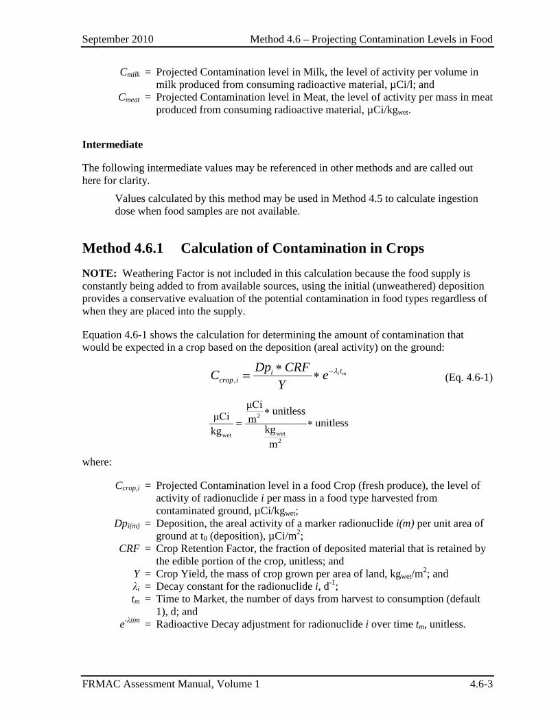
September 2010 Method 4.6 – Projecting Contamination Levels in Food
FRMAC Assessment Manual, Volume 1 4.6-3
Cmilk = Projected Contamination level in Milk, the level of activity per volume in milk produced from consuming radioactive material, µCi/l; and
Cmeat = Projected Contamination level in Meat, the level of activity per mass in meat produced from consuming radioactive material, µCi/kgwet.
Intermediate
The following intermediate values may be referenced in other methods and are called out here for clarity.
Values calculated by this method may be used in Method 4.5 to calculate ingestion dose when food samples are not available.
Method 4.6.1 Calculation of Contamination in Crops NOTE: Weathering Factor is not included in this calculation because the food supply is constantly being added to from available sources, using the initial (unweathered) deposition provides a conservative evaluation of the potential contamination in food types regardless of when they are placed into the supply.
Equation 4.6-1 shows the calculation for determining the amount of contamination that would be expected in a crop based on the deposition (areal activity) on the ground:
,i mti
crop iDp CRFC e
Yλ−∗
= ∗ (Eq. 4.6-1)
2
wetwet2
μCi unitlessμCi m unitlesskgkgm
∗= ∗
where:
Ccrop,i = Projected Contamination level in a food Crop (fresh produce), the level of activity of radionuclide i per mass in a food type harvested from contaminated ground, µCi/kgwet;
Dpi(m) = Deposition, the areal activity of a marker radionuclide i(m) per unit area of ground at t0 (deposition), µCi/m2;
CRF = Crop Retention Factor, the fraction of deposited material that is retained by the edible portion of the crop, unitless; and
Y = Crop Yield, the mass of crop grown per area of land, kgwet/m2; and λi = Decay constant for the radionuclide i, d-1; tm = Time to Market, the number of days from harvest to consumption (default
1), d; and e-λitm = Radioactive Decay adjustment for radionuclide i over time tm, unitless.
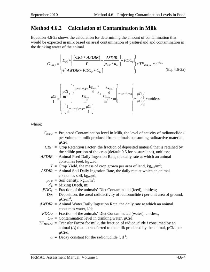
September 2010 Method 4.6 – Projecting Contamination Levels in Food
FRMAC Assessment Manual, Volume 1 4.6-4
Method 4.6.2 Calculation of Contamination in Milk Equation 4.6-2a shows the calculation for determining the amount of contamination that would be expected in milk based on areal contamination of pastureland and contamination in the drinking water of the animal.
( )
[ ], , ,
i mi F tsoil mmilk i Milk A i
W W
CRF AFDIR ASDIRDp FDCY dC TF e
AWDIR FDC C
λρ −
∗∗ + ∗ ∗= ∗ ∗
+ ∗ ∗ (Eq. 4.6-2a)
wet soil
2wet soil2 3
kg kgunitlessμCi d d μCiunitlesskg kgμCi m lm unitlessμCim ml
dl μCiunitlessd l
∗ ∗ + ∗ ∗= ∗ ∗ + ∗ ∗
where: Cmilk,i = Projected Contamination level in Milk, the level of activity of radionuclide i
per volume in milk produced from animals consuming radioactive material, µCi/l;
CRF = Crop Retention Factor, the fraction of deposited material that is retained by the edible portion of the crop (default 0.5 for pastureland), unitless;
AFDIR = Animal Feed Daily Ingestion Rate, the daily rate at which an animal consumes feed, kgwet/d;
Y = Crop Yield, the mass of crop grown per area of land, kgwet/m2; ASDIR = Animal Soil Daily Ingestion Rate, the daily rate at which an animal
consumes soil, kgsoil/d; ρsoil = Soil density, kgsoil/m3; dm = Mixing Depth, m; FDCF = Fraction of the animals’ Diet Contaminated (feed), unitless; Dpi = Deposition, the areal radioactivity of radionuclide i per unit area of ground,
µCi/m2; AWDIR = Animal Water Daily Ingestion Rate, the daily rate at which an animal
consumes water, l/d; FDCW = Fraction of the animals’ Diet Contaminated (water), unitless; CW = Contamination level in drinking water, µCi/l; TFMilk,A,i = Transfer Factor for milk, the fraction of radionuclide i consumed by an
animal (A) that is transferred to the milk produced by the animal, µCi/l per µCi/d;
λi = Decay constant for the radionuclide i, d-1;
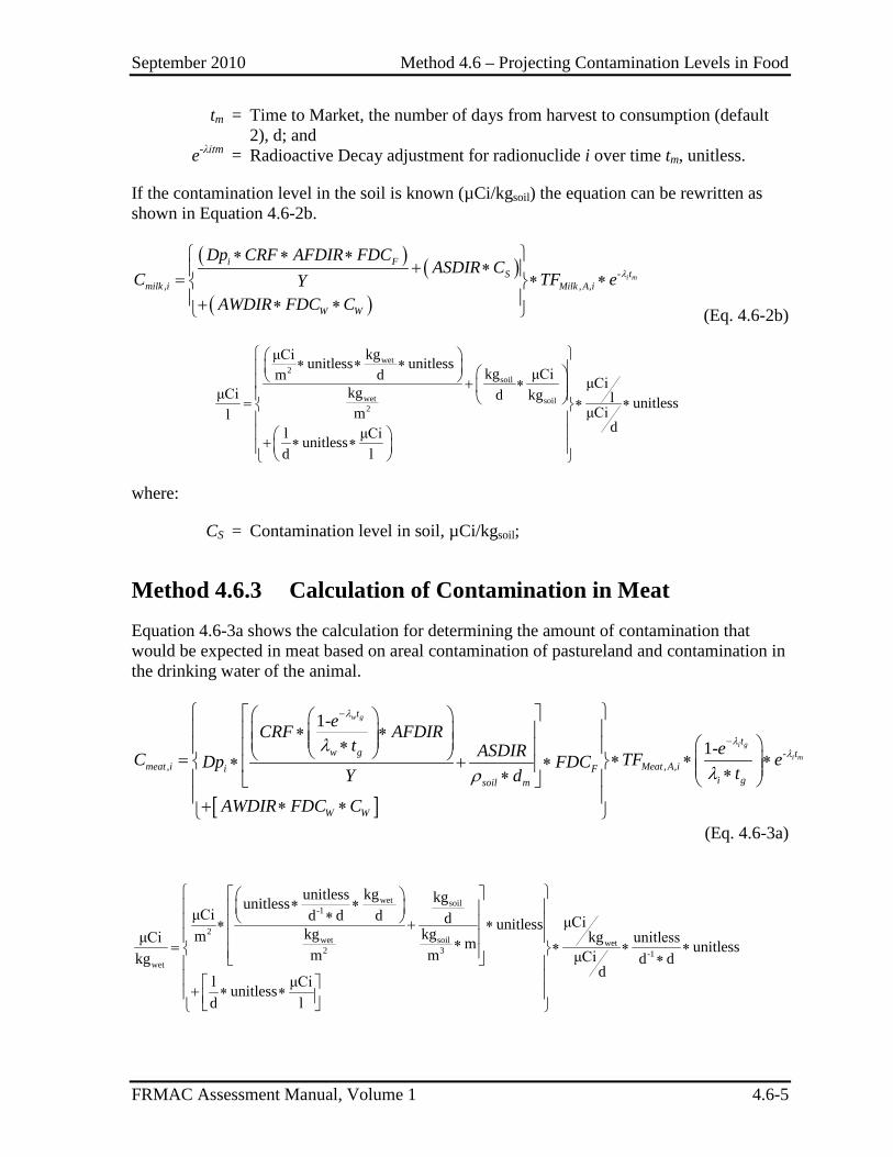
September 2010 Method 4.6 – Projecting Contamination Levels in Food
FRMAC Assessment Manual, Volume 1 4.6-5
tm = Time to Market, the number of days from harvest to consumption (default 2), d; and
e-λitm = Radioactive Decay adjustment for radionuclide i over time tm, unitless.
If the contamination level in the soil is known (µCi/kgsoil) the equation can be rewritten as shown in Equation 4.6-2b.
( ) ( )
( )-
, , ,i m
i FtS
milk i Milk A i
W W
Dp CRF AFDIR FDCASDIR C
C TF eYAWDIR FDC C
λ
∗ ∗ ∗+ ∗ = ∗ ∗
+ ∗ ∗ (Eq. 4.6-2b)
wet2
soil
wet soil2
kgμCi unitless unitlesskg μCim d μCi
kgμCi d kg l unitlessμCimldl μCiunitless
d l
∗ ∗ ∗ + ∗ = ∗ ∗ + ∗ ∗
where:
CS = Contamination level in soil, µCi/kgsoil;
Method 4.6.3 Calculation of Contamination in Meat Equation 4.6-3a shows the calculation for determining the amount of contamination that would be expected in meat based on areal contamination of pastureland and contamination in the drinking water of the animal.
[ ]
-, , ,
1-1-
w g
i g
i m
t
tw g t
meat i Meat A ii Fi gsoil m
W W
eCRF AFDIRt eASDIRC TF eDp FDC tY d
AWDIR FDC C
λ
λλλ
λρ
−
−
∗ ∗ ∗ = ∗ ∗ ∗ ∗ + ∗ ∗∗ + ∗ ∗
(Eq. 4.6-3a)
wet soil
-1
2wet soil wet2 3 -1
wet
kgunitless kgunitlessμCi d d d d μCiunitlesskg kgm kgμCi unitlessm unitlessm m μCikg d d
dl μCiunitlessd l
∗ ∗ ∗ ∗ + ∗ ∗= ∗ ∗ ∗ ∗ + ∗ ∗

September 2010 Method 4.6 – Projecting Contamination Levels in Food
FRMAC Assessment Manual, Volume 1 4.6-6
where:
Cmeat,i = Projected Contamination level in Meat, the level of activity of radionuclide i per mass in an animal’s meat from consuming radioactive material, µCi/kgwet;
CRF = Crop Retention Factor, the fraction of deposited material that is retained by the edible portion of the crop (default 0.5 for pastureland), unitless;
tg = Grazing Time, time from deposition or sampling to the end of the grazing period, d;
λw = Decay constant for weathering radioactive material off plants (default 4.62E-02, corresponds to a 15 day half life), d-1;
-1-e w gt
w gt
λ
λ ∗
= Integrated average weathering of radioactive material off plants during the
time the animal is grazing in the field (the integral of the weathering over the Grazing Time divided by the Grazing Time), unitless;
AFDIR = Animal Feed Daily Ingestion Rate, the daily rate at which an animal consumes feed, kgwet/d;
Y = Crop Yield, the mass of crop grown per area of land, kgwet/m2; ASDIR = Animal Soil Daily Ingestion Rate, the daily rate at which an animal
consumes soil, kgsoil/d; ρsoil = Soil density, kgsoil/m3; dm = Mixing Depth, m; FDCF = Fraction of the animals’ Diet Contaminated (feed), unitless; Dpi = Deposition, the areal radioactivity of radionuclide i per unit area of ground,
µCi/m2; AWDIR = Animal Water Daily Ingestion Rate, the daily rate at which an animal
consumes water, l/d; FDCW = Fraction of the animals’ Diet Contaminated (water), unitless; CW = Contamination level in drinking water, µCi/l; TFMeat,A,i = Transfer Factor for meat, the fraction of radionuclide i consumed by an
animal (A) that is transferred to the meat of the animal, µCi/kgwet per µCi/d;
λi = Decay constant for the radionuclide i, d-1;
-1-e i gt
i gt
λ
λ ∗
= Integrated average decay of radioactive material during the time the animal
is grazing in the field (the integral of radioactive decay over the Grazing Time divided by the Grazing Time), unitless;
tm = Time to Market, the number of days from harvest to consumption, d; and e-λitm = Radioactive Decay adjustment for radionuclide i over time tm, unitless.
If the contamination level in the soil is known (µCi/kgsoil) the equation can be rewritten as shown in Equation 4.6-3b.
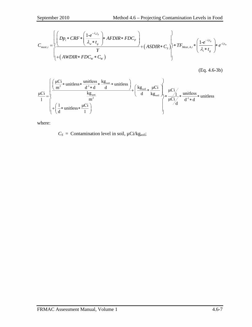
September 2010 Method 4.6 – Projecting Contamination Levels in Food
FRMAC Assessment Manual, Volume 1 4.6-7
( )
( )
-, , ,
1-1-
w g
i g
i m
t
i F ttw g
meat i Meat A iSi g
W W
eDp CRF AFDIR FDCt eC TF eASDIR C tY
AWDIR FDC C
λ
λλλ
λ
−
−
∗ ∗ ∗ ∗ ∗ = ∗ ∗ ∗ + ∗ ∗ + ∗ ∗
(Eq. 4.6-3b)
wet2 -1
soil
wet soil2 -1
kgμCi unitlessunitless unitlesskg μCim d d d μCi
kgμCi unitlessd kg l unitlessμCiml d ddl μCiunitless
d l
∗ ∗ ∗ ∗ ∗ + ∗ = ∗ ∗ ∗ ∗ + ∗ ∗
where:
CS = Contamination level in soil, µCi/kgsoil;
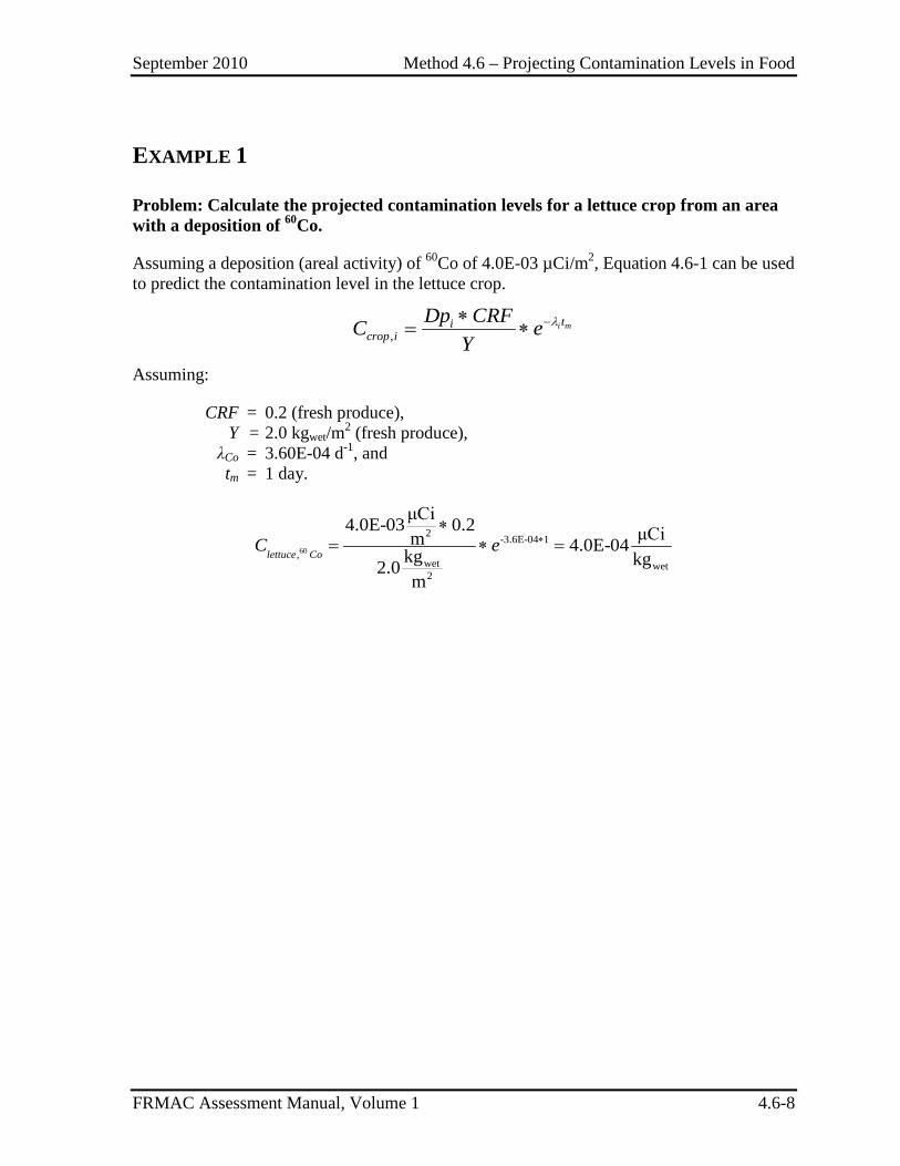
September 2010 Method 4.6 – Projecting Contamination Levels in Food
FRMAC Assessment Manual, Volume 1 4.6-8
EXAMPLE 1
Problem: Calculate the projected contamination levels for a lettuce crop from an area with a deposition of 60Co.
Assuming a deposition (areal activity) of 60Co of 4.0E-03 µCi/m2, Equation 4.6-1 can be used to predict the contamination level in the lettuce crop.
,i mti
crop iDp CRFC e
Yλ−∗
= ∗
Assuming:
CRF = 0.2 (fresh produce), Y = 2.0 kgwet/m2 (fresh produce), λCo = 3.60E-04 d-1, and tm = 1 day.
60
2 -3.6E-04 1,
wet wet2
μCi4.0E-03 0.2 μCim 4.0E-04kg kg2.0m
lettuce CoC e ∗
∗= ∗ =
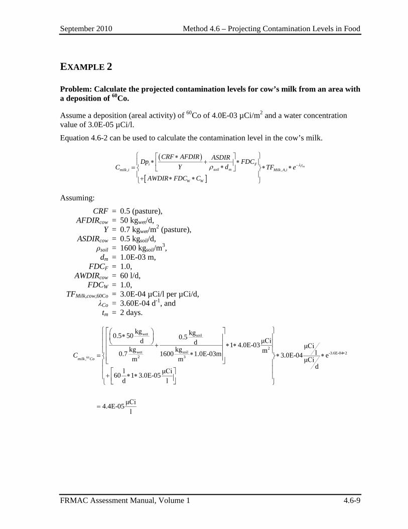
September 2010 Method 4.6 – Projecting Contamination Levels in Food
FRMAC Assessment Manual, Volume 1 4.6-9
EXAMPLE 2
Problem: Calculate the projected contamination levels for cow’s milk from an area with a deposition of 60Co.
Assume a deposition (areal activity) of 60Co of 4.0E-03 µCi/m2 and a water concentration value of 3.0E-05 µCi/l.
Equation 4.6-2 can be used to calculate the contamination level in the cow’s milk.
( )
[ ], , ,
i mi F tsoil mmilk i Milk A i
W W
CRF AFDIR ASDIRDp FDCY dC TF e
AWDIR FDC C
λρ −
∗∗ + ∗ ∗= ∗ ∗
+ ∗ ∗
Assuming:
CRF = 0.5 (pasture), AFDIRcow = 50 kgwet/d, Y = 0.7 kgwet/m2 (pasture), ASDIRcow = 0.5 kgsoil/d, ρsoil = 1600 kgsoil/m3, dm = 1.0E-03 m, FDCF = 1.0, AWDIRcow = 60 l/d, FDCW = 1.0, TFMilk,cow,60Co = 3.0E-04 µCi/l per µCi/d, λCo = 3.60E-04 d-1, and tm = 2 days.
60
wet soil
2wet soil -3.6E-04 22 3,
kg kg0.5 50 0.5 μCid d 1 4.0E-03 μCikg kg m l0.7 1600 1.0E-03m 3.0E-04 em m μCidl μCi60 1 3.0E-05
d l
μCi4.4E-05l
milk CoC ∗
∗ + ∗ ∗ ∗= ∗ ∗ + ∗ ∗
=
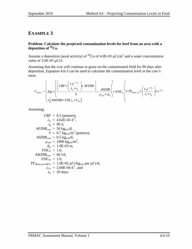
September 2010 Method 4.6 – Projecting Contamination Levels in Food
FRMAC Assessment Manual, Volume 1 4.6-10
EXAMPLE 3
Problem: Calculate the projected contamination levels for beef from an area with a deposition of 60Co.
Assume a deposition (areal activity) of 60Co of 4.0E-03 µCi/m2 and a water concentration value of 3.0E-05 µCi/l.
Assuming that the cow will continue to graze on the contaminated field for 90 days after deposition, Equation 4.6-3 can be used to calculate the contamination level in the cow’s meat.
[ ]
-, , ,
1-1-
w g
i g
i m
t
tw g t
meat i Meat A ii Fi gsoil m
W W
eCRF AFDIRt eASDIRC TF eDp FDC tY d
AWDIR FDC C
λ
λλλ
λρ
−
−
∗ ∗ ∗ = ∗ ∗ ∗ ∗ + ∗ ∗∗ + ∗ ∗
Assuming:
CRF = 0.5 (pasture), λw = 4.62E-02 d-1, tg = 90 d, AFDIRcow = 50 kgwet/d, Y = 0.7 kgwet/m2 (pasture), ASDIRcow = 0.5 kgsoil/d, ρsoil = 1600 kgsoil/m3, dm = 1.0E-03 m, FDCF = 1.0, AWDIRcow = 60 l/d, FDCW = 1.0, TFMeat,cow,60Co = 1.0E-02 µCi/kgwet per µCi/d, λCo = 3.60E-04 d-1, and tm = 20 days.
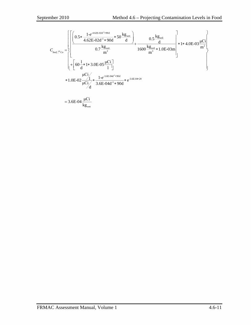
September 2010 Method 4.6 – Projecting Contamination Levels in Food
FRMAC Assessment Manual, Volume 1 4.6-11
-1
60
-4.62E-02d 90dwet
soil-1
2wet soil2 3,
kg1- kg0.5 50 0.54.62E-02d 90d d μCid 1 4.0E-03kg kg m0.7 1600 1.0E-03mm m
l μCi60 1 3.0E-05d lμCi
l1.0E-02 μCid
beef Co
e
C
∗ ∗ ∗ ∗ + ∗ ∗ ∗ =
+ ∗ ∗
∗-1-3.6E-04d 90d
-3.6E-04 20-1
wet
1- e3.6E-04d 90d
μCi3.6E-04kg
e ∗∗∗ ∗
∗
=
September 2010 Method 4.6 – Projecting Contamination Levels in Food
FRMAC Assessment Manual, Volume 1 4.6-12
This page intentionally left blank.

September 2010 Method 4.7 – Dose from Inadvertent Soil Ingestion
FRMAC Assessment Manual, Volume 1 4.7-1
METHOD 4.7 DOSE FROM INADVERTENT SOIL INGESTION
Application This method calculates the Ingestion Dose from the inadvertent consumption of soil that has been contaminated with radioactive material.
The Ingestion Dose Method:
• Can be applied to the whole body (E50) or to a specific organ (HT,50)
• Uses monitoring results of areal activity to calculate the dose that a receptor is projected to receive over a specified time phase (generally 1 year) due to ingestion of the contaminated soil.
• Is used to define dose levels to assist decision makers in determining where it may be advisable to implement protective actions.
Discussion This method calculates the projected dose from the inadvertent ingestion of soil contaminated by radioactive material and is calculated by evaluating ground monitoring results (µCi/m2). Ingestion of contaminated dirt can occur when surface contamination is transferred from a surface to hands, toys, cigarettes, etc.
Generally the contribution of this pathway is minor. However, it can become significant and even dominant in certain special cases. One such case is for long-term residence or outdoor work in areas contaminated with aged plutonium in surface soil.
If the dose from this pathway exceeds 10% of the appropriate EPA PAG for the Time Phase, it should be included in a decision for protective actions.
Assumptions The FRMAC radiological assessment calculations use the default assumptions established by the FRMAC Assessment Working Group. The following default assumptions are used in this method:
1) Default soil intake rates are 5.0E-05 kgsoil/day for adults and 1.0E-04 kgsoil/day for children (EPA97a). This method uses the conservative value of 1.0E-04 kgsoil/day for all calculations. If specific intake rates are known, use those instead of defaults.
2) Soil density of 1600 kgsoil/m3.
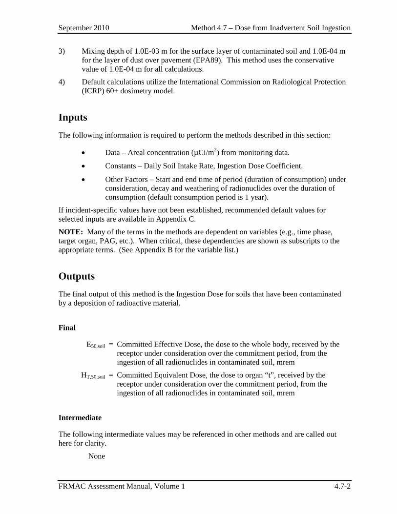
September 2010 Method 4.7 – Dose from Inadvertent Soil Ingestion
FRMAC Assessment Manual, Volume 1 4.7-2
3) Mixing depth of 1.0E-03 m for the surface layer of contaminated soil and 1.0E-04 m for the layer of dust over pavement (EPA89). This method uses the conservative value of 1.0E-04 m for all calculations.
4) Default calculations utilize the International Commission on Radiological Protection (ICRP) 60+ dosimetry model.
Inputs The following information is required to perform the methods described in this section:
• Data – Areal concentration (µCi/m2) from monitoring data.
• Constants – Daily Soil Intake Rate, Ingestion Dose Coefficient.
• Other Factors – Start and end time of period (duration of consumption) under consideration, decay and weathering of radionuclides over the duration of consumption (default consumption period is 1 year).
If incident-specific values have not been established, recommended default values for selected inputs are available in Appendix C. NOTE: Many of the terms in the methods are dependent on variables (e.g., time phase, target organ, PAG, etc.). When critical, these dependencies are shown as subscripts to the appropriate terms. (See Appendix B for the variable list.)
Outputs The final output of this method is the Ingestion Dose for soils that have been contaminated by a deposition of radioactive material.
Final
E50,soil = Committed Effective Dose, the dose to the whole body, received by the receptor under consideration over the commitment period, from the ingestion of all radionuclides in contaminated soil, mrem
HT,50,soil = Committed Equivalent Dose, the dose to organ “t”, received by the receptor under consideration over the commitment period, from the ingestion of all radionuclides in contaminated soil, mrem
Intermediate
The following intermediate values may be referenced in other methods and are called out here for clarity.
None
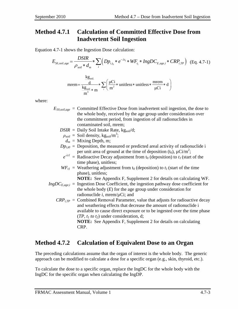
September 2010 Method 4.7 – Dose from Inadvertent Soil Ingestion
FRMAC Assessment Manual, Volume 1 4.7-3
Method 4.7.1 Calculation of Committed Effective Dose from Inadvertent Soil Ingestion
Equation 4.7-1 shows the Ingestion Dose calculation:
( )1
0 150, , , , , ,t
soil age i t t E age i i TPisoil m
DSIRE Dp e WF IngDC CRPd
λ
ρ−= ∗ ∗ ∗ ∗ ∗
∗ ∑ (Eq. 4.7-1)
soil
2soil3
kgμCi mremdmrem unitless unitless dkg m μCim
mi
= ∗ ∗ ∗ ∗ ∗
∗∑
where:
E50,soil,age = Committed Effective Dose from inadvertent soil ingestion, the dose to the whole body, received by the age group under consideration over the commitment period, from ingestion of all radionuclides in contaminated soil, mrem;
DSIR = Daily Soil Intake Rate, kgsoil/d; ρsoil = Soil density, kgsoil/m3; dm = Mixing Depth, m; Dpi,t0 = Deposition, the measured or predicted areal activity of radionuclide i
per unit area of ground at the time of deposition (t0), µCi/m2; e-λt1 = Radioactive Decay adjustment from t0 (deposition) to t1 (start of the
time phase), unitless; WFt1 = Weathering adjustment from t0 (deposition) to t1 (start of the time
phase), unitless; NOTE: See Appendix F, Supplement 2 for details on calculating WF.
IngDCE,age,i = Ingestion Dose Coefficient, the ingestion pathway dose coefficient for the whole body (E) for the age group under consideration for radionuclide i, mrem/µCi; and
CRPi,TP = Combined Removal Parameter, value that adjusts for radioactive decay and weathering effects that decrease the amount of radionuclide i available to cause direct exposure or to be ingested over the time phase (TP, t1 to t2) under consideration, d; NOTE: See Appendix F, Supplement 2 for details on calculating CRP.
Method 4.7.2 Calculation of Equivalent Dose to an Organ The preceding calculations assume that the organ of interest is the whole body. The generic approach can be modified to calculate a dose for a specific organ (e.g., skin, thyroid, etc.).
To calculate the dose to a specific organ, replace the IngDC for the whole body with the IngDC for the specific organ when calculating the IngDP.
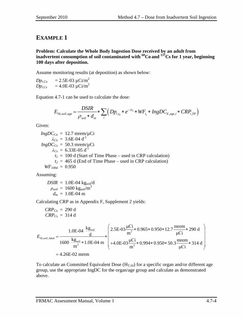
September 2010 Method 4.7 – Dose from Inadvertent Soil Ingestion
FRMAC Assessment Manual, Volume 1 4.7-4
EXAMPLE 1
Problem: Calculate the Whole Body Ingestion Dose received by an adult from inadvertent consumption of soil contaminated with 60Co and 137Cs for 1 year, beginning 100 days after deposition.
Assume monitoring results (at deposition) as shown below:
Dpi,Co = 2.5E-03 µCi/m2 Dpi,Cs = 4.0E-03 µCi/m2
Equation 4.7-1 can be used to calculate the dose:
( )1
0 150, , , , , ,t
soil age i t t E age i i TPisoil m
DSIRE Dp e WF IngDC CRPd
λ
ρ−= ∗ ∗ ∗ ∗ ∗
∗ ∑
Given:
IngDCCo = 12.7 mrem/µCi λCo = 3.6E-04 d-1 IngDCCs = 50.3 mrem/µCi λCs = 6.33E-05 d-1
t1 = 100 d (Start of Time Phase – used in CRP calculation) t2 = 465 d (End of Time Phase – used in CRP calculation) WF100d = 0.950
Assuming:
DSIR = 1.0E-04 kgsoil/d ρsoil = 1600 kgsoil/m3 dm = 1.0E-04 m
Calculating CRP as in Appendix F, Supplement 2 yields:
CRPCo = 290 d CRPCs = 314 d
soil 2
50, ,soil3 2
μCi mremkg 2.5E-03 0.965 0.950 12.7 290 d1.0E-04 m μCidkg μCi mrem1600 1.0E-04 m 4.0E-03 0.994 0.950 50.3 314 dm m μCi
4.26E-02 mrem
soil AdultE
∗ ∗ ∗ ∗ = ∗ ∗ + ∗ ∗ ∗ ∗
=
To calculate an Committed Equivalent Dose (HT,50) for a specific organ and/or different age group, use the appropriate IngDC for the organ/age group and calculate as demonstrated above.
September 2010 Section 5 – Sample Management Methods
FRMAC Assessment Manual, Volume 1 5.0-1
SECTION 5. SAMPLE MANAGEMENT METHODS
Effective Date
Introduction .............................................................................................. 5.0-3 9/2010
Method 5.1 Determining Resuspension from Samples............................ 5.1-1 9/2010
Method 5.2 Comparing Sample Results to Ingestion Pathway Thresholds ............................................................................ 5.2-1 9/2010
Method 5.3 Normalizing Samples ........................................................... 5.3-1 Reserved
Method 5.4 Determining Laboratory Analysis MDA Requirements ....... 5.4-1 Reserved
September 2010 Section 5 – Sample Management Methods
FRMAC Assessment Manual, Volume 1 5.0-2
This page intentionally left blank.
September 2010 Section 5 – Sample Management Methods
FRMAC Assessment Manual, Volume 1 5.0-3
INTRODUCTION TO SAMPLE MANAGEMENT METHODS
These methods describe how to use sample data to perform various assessment activities. The results of these methods may be used to determine alternate (non default) input factors that may be used to calculate values that are more applicable to the incident being assessed. These methods may also be used to normalize sample data for comparison to values calculated by other methods.

September 2010 Section 5 – Sample Management Methods
FRMAC Assessment Manual, Volume 1 5.0-4
This page intentionally left blank.
September 2010 Method 5.1 – Determining Resuspension From Samples
FRMAC Assessment Manual, Volume 1 5.1-1
METHOD 5.1 DETERMINING RESUSPENSION FROM SAMPLES
Application This method has been developed to calculate a Resuspension Factor based on air and deposition samples.
The Resuspension Factor (K):
• Represents the ratio of activity in the air at a particular location to the activity on the ground at that location for a particular radionuclide.
NOTE: Resuspension Factors may be different for each radionuclide in a mixture because some chemical/physical forms may be more likely to become airborne than others. Local decision makers should be consulted to determine if radionuclide-specific Resuspension Factors should be used instead of one factor for the entire mixture.
• Is used to calculate the Resuspension Parameter (KP) and Inhalation Dose Parameter for Deposition (InhDP_Dp) for each radionuclide in a deposition mixture.
Discussion
This calculation is presented as an alternative to the default, time dependent, formula from NCRP 129 shown in Appendix F, Supplement 2 and may be used only with approval from local decision makers.
In contrast to direct measurements of air concentration (usually made at occupied locations), air and ground measurements used for determining resuspension factors must be made at or near source locations – i.e., areas of contaminated ground from which activity is being resuspended into occupied areas. Although it is possible that such source areas may be near (or may be the same as) occupied areas, it is also possible that the source contamination area is some distance away from the occupied area of interest.
Therefore, the location of resuspension measurements must take into account the geography and weather factors that affect the transfer of activity from the ground to the air that will end up in the occupied areas of interest. In general, resuspension measurements should be made at locations in contaminated areas that are upwind (or may be expected to be upwind) of the occupied areas of interest.
Several ground samples should be taken upwind of each air sampler in order to obtain an average value for the ground in the area covered by the air sampler. The purpose of these
September 2010 Method 5.1 – Determining Resuspension From Samples
FRMAC Assessment Manual, Volume 1 5.1-2
measurements is to obtain the general level of ground activity for comparison to the measured activity on the air filter.
There are several pitfalls to consider when deciding to use a sample based resuspension value:
• It may be difficult to obtain accurate/representative sample-based values. • Hot particles may significantly skew the air sample activity results. • Samples are only representative of the resuspension factor for a specific point in
time and space. • Resuspension may change over the time phase of interest as the land use changes. • Weathering processes and alpha-recoil energy can break apart contaminated
particles creating smaller particle sizes over time potentially changing resuspension.
• Sample based resuspension values are sensitive to many factors, including: – Air sampler location, – Wind direction relative to the air sample location, and – Activities being conducted in the sampling area.
Assumptions The following default assumptions are used in this method:
None
Inputs The following information is required to perform the methods described in this section:
Data – Sampling Results from air and ground monitoring.
Outputs The final output of this method is the resuspension factor for a radionuclide contaminant.
Final
Ki = Resuspension Factor, the ratio of the activity level in the air to the level on the ground of radionuclide i, m-1.
Intermediate
The following intermediate values may be referenced in other methods and are called out here for clarity.
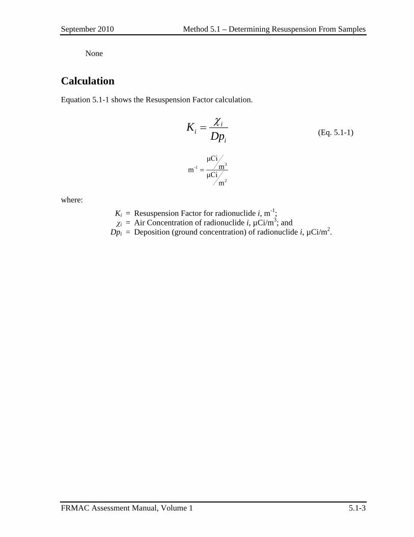
September 2010 Method 5.1 – Determining Resuspension From Samples
FRMAC Assessment Manual, Volume 1 5.1-3
None
Calculation Equation 5.1-1 shows the Resuspension Factor calculation.
χ
= ii
i
KDp (Eq. 5.1-1)
3-1
2
μCimm
μCim
=
where:
Ki = Resuspension Factor for radionuclide i, m-1; χi = Air Concentration of radionuclide i, µCi/m3; and Dpi = Deposition (ground concentration) of radionuclide i, µCi/m2.
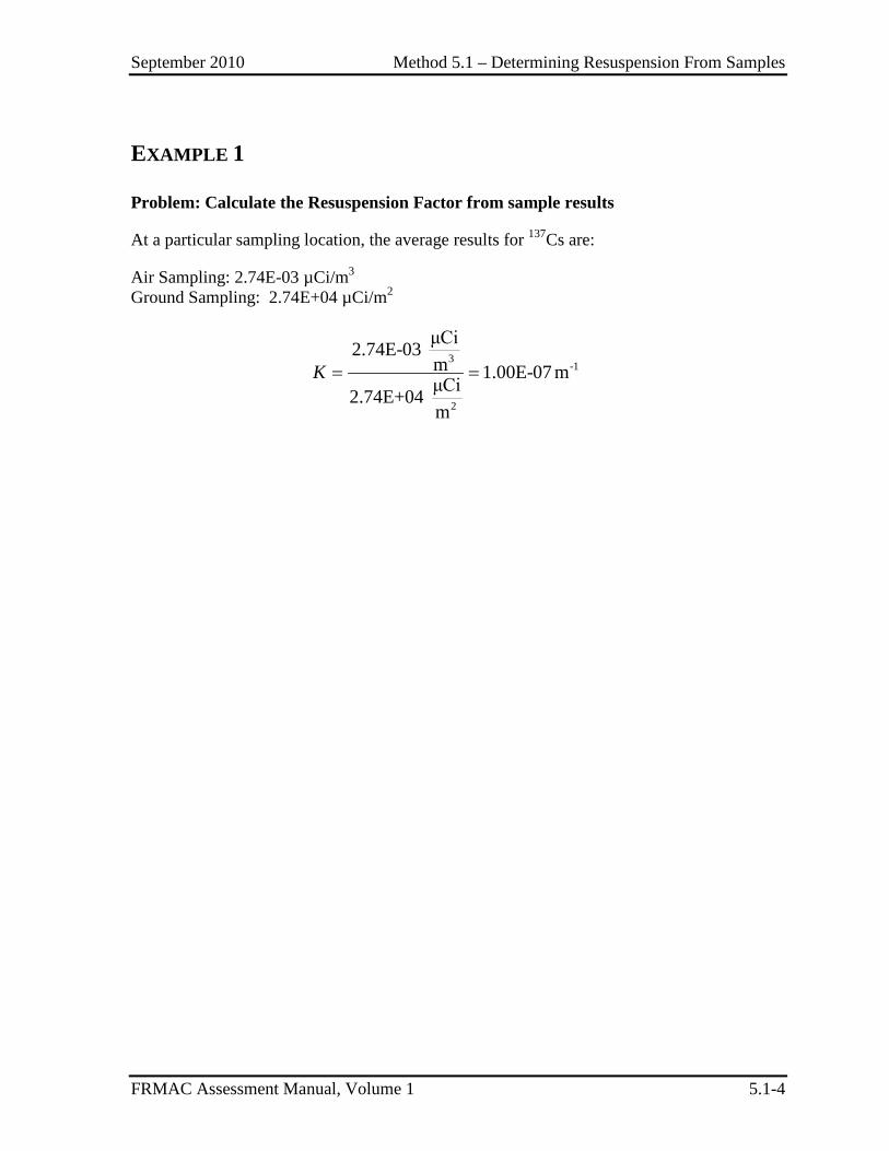
September 2010 Method 5.1 – Determining Resuspension From Samples
FRMAC Assessment Manual, Volume 1 5.1-4
EXAMPLE 1
Problem: Calculate the Resuspension Factor from sample results
At a particular sampling location, the average results for 137Cs are:
Air Sampling: 2.74E-03 µCi/m3 Ground Sampling: 2.74E+04 µCi/m2
3
-1
2
μCi2.74E-03 m 1.00E-07 mμCi2.74E+04 m
K = =
September 2010 Method 5.2 – Comparing Sample Results to Ingestion Pathway Thresholds
FRMAC Assessment Manual, Volume 1 5.2-1
METHOD 5.2 COMPARING SAMPLE RESULTS TO INGESTION PATHWAY THRESHOLDS
Application This method provides instructions on how to compare analytical sample results of food and fodder to DILs.
Discussion DILs are based on the level of radioactive material in food “as prepared for consumption.” The default assumption for this method is that food products are intended to be eaten in a fresh or “wet” condition.
Because many methods of sample analysis require drying the sample material it may be necessary to apply a dry-to-wet conversion factor to the sample results before a direct comparison may be made to the appropriate DIL. Assessment Scientists must determine when it is appropriate to apply the dry-to-wet conversion factor to sample results for comparison to the DIL.
Assumptions The FRMAC radiological assessment calculations use the default assumptions established by the FDA. The following default assumptions are used in this method:
• Food products are intended to be eaten in a fresh or “wet” condition. This does not apply to fodder that is to be fed to livestock in a dry form.
Inputs The following information is required to perform the methods described in this section:
Data – Sampling Results from food products/fodder in terms of dry mass (µCi/kgdry).
Constants – Mass Conversion Factor for the food product/fodder.
If incident-specific values have not been established, recommended default values for selected inputs are available in Appendix C. NOTE: Many of the terms in the methods are dependent on variables (e.g., time phase, target organ, PAG, etc.). When critical, these dependencies are shown as subscripts to the appropriate terms. (See Appendix B for the variable list.)
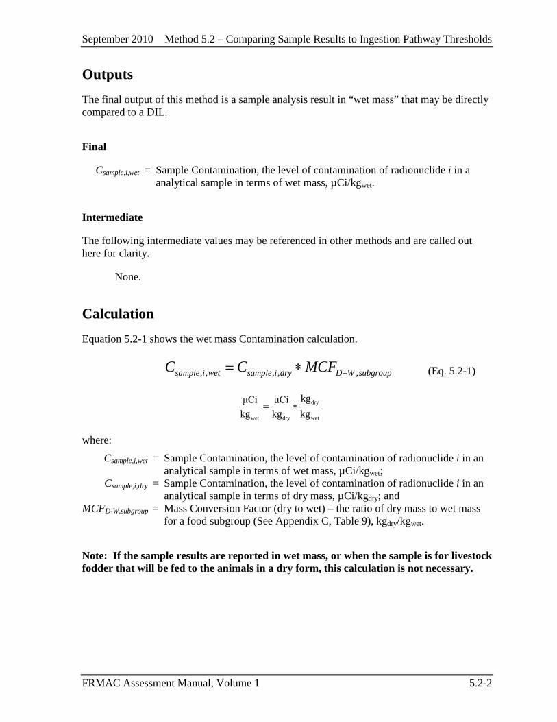
September 2010 Method 5.2 – Comparing Sample Results to Ingestion Pathway Thresholds
FRMAC Assessment Manual, Volume 1 5.2-2
Outputs The final output of this method is a sample analysis result in “wet mass” that may be directly compared to a DIL.
Final
Csample,i,wet = Sample Contamination, the level of contamination of radionuclide i in a analytical sample in terms of wet mass, µCi/kgwet.
Intermediate
The following intermediate values may be referenced in other methods and are called out here for clarity.
None.
Calculation Equation 5.2-1 shows the wet mass Contamination calculation.
, , , , ,sample i wet sample i dry D W subgroupC C MCF −= ∗ (Eq. 5.2-1)
dry
wet dry wet
kgμCi μCikg kg kg
= ∗
where:
Csample,i,wet = Sample Contamination, the level of contamination of radionuclide i in an analytical sample in terms of wet mass, µCi/kgwet;
Csample,i,dry = Sample Contamination, the level of contamination of radionuclide i in an analytical sample in terms of dry mass, µCi/kgdry; and
MCFD-W,subgroup = Mass Conversion Factor (dry to wet) – the ratio of dry mass to wet mass for a food subgroup (See Appendix C, Table 9), kgdry/kgwet.
Note: If the sample results are reported in wet mass, or when the sample is for livestock fodder that will be fed to the animals in a dry form, this calculation is not necessary.
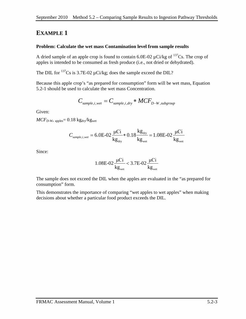
September 2010 Method 5.2 – Comparing Sample Results to Ingestion Pathway Thresholds
FRMAC Assessment Manual, Volume 1 5.2-3
EXAMPLE 1
Problem: Calculate the wet mass Contamination level from sample results
A dried sample of an apple crop is found to contain 6.0E-02 µCi/kg of 137Cs. The crop of apples is intended to be consumed as fresh produce (i.e., not dried or dehydrated).
The DIL for 137Cs is 3.7E-02 µCi/kg; does the sample exceed the DIL?
Because this apple crop’s “as prepared for consumption” form will be wet mass, Equation 5.2-1 should be used to calculate the wet mass Concentration.
, , , , ,sample i wet sample i dry D W subgroupC C MCF −= ∗
Given:
MCFD-W, apples= 0.18 kgdry/kgwet
dry, ,
dry wet wet
kgμCi μCi6.0E-02 0.18 1.08E-02kg kg kgsample i wetC = ∗ =
Since:
wet wet
μCi μCi1.08E-02 3.7E-02kg kg
<
The sample does not exceed the DIL when the apples are evaluated in the “as prepared for consumption” form.
This demonstrates the importance of comparing “wet apples to wet apples” when making decisions about whether a particular food product exceeds the DIL.
September 2010 Method 5.2 – Comparing Sample Results to Ingestion Pathway Thresholds
FRMAC Assessment Manual, Volume 1 5.2-4
This page intentionally left blank.
September 2010 Method 5.3 – Normalizing Samples
FRMAC Assessment Manual, Volume 1 5.3-1
METHOD 5.3 NORMALIZING SAMPLES
This method is reserved for future development.

September 2010 Method 5.3 – Normalizing Samples
FRMAC Assessment Manual, Volume 1 5.3-2
This page intentionally left blank.
September 2010 Method 5.4 – Determining MDA Requirements
FRMAC Assessment Manual, Volume 1 5.4-1
METHOD 5.4 DETERMINING MDA REQUIREMENTS
This method is reserved for future development.
September 2010 Method 5.4 – Determining MDA Requirements
FRMAC Assessment Manual, Volume 1 5.4-2
This page intentionally left blank.
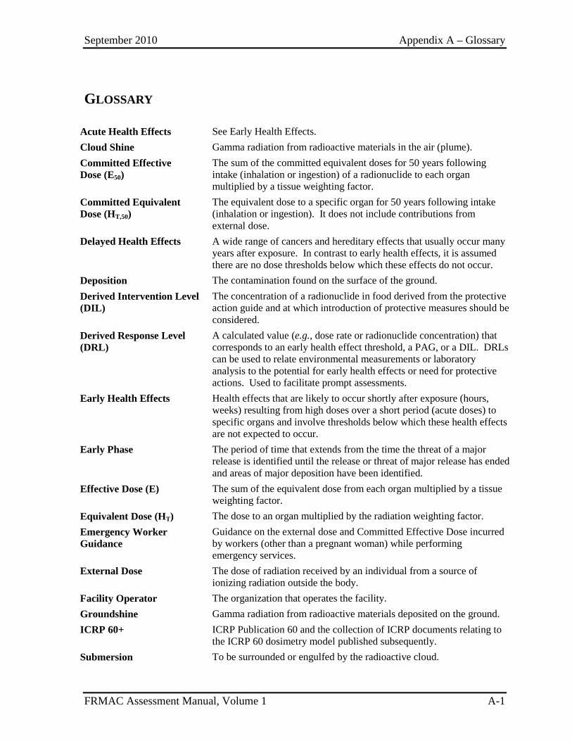
September 2010 Appendix A – Glossary
FRMAC Assessment Manual, Volume 1 A-1
GLOSSARY
Acute Health Effects See Early Health Effects. Cloud Shine Gamma radiation from radioactive materials in the air (plume). Committed Effective Dose (E50)
The sum of the committed equivalent doses for 50 years following intake (inhalation or ingestion) of a radionuclide to each organ multiplied by a tissue weighting factor.
Committed Equivalent Dose (HT,50)
The equivalent dose to a specific organ for 50 years following intake (inhalation or ingestion). It does not include contributions from external dose.
Delayed Health Effects A wide range of cancers and hereditary effects that usually occur many years after exposure. In contrast to early health effects, it is assumed there are no dose thresholds below which these effects do not occur.
Deposition The contamination found on the surface of the ground. Derived Intervention Level (DIL)
The concentration of a radionuclide in food derived from the protective action guide and at which introduction of protective measures should be considered.
Derived Response Level (DRL)
A calculated value (e.g., dose rate or radionuclide concentration) that corresponds to an early health effect threshold, a PAG, or a DIL. DRLs can be used to relate environmental measurements or laboratory analysis to the potential for early health effects or need for protective actions. Used to facilitate prompt assessments.
Early Health Effects Health effects that are likely to occur shortly after exposure (hours, weeks) resulting from high doses over a short period (acute doses) to specific organs and involve thresholds below which these health effects are not expected to occur.
Early Phase The period of time that extends from the time the threat of a major release is identified until the release or threat of major release has ended and areas of major deposition have been identified.
Effective Dose (E) The sum of the equivalent dose from each organ multiplied by a tissue weighting factor.
Equivalent Dose (HT) The dose to an organ multiplied by the radiation weighting factor. Emergency Worker Guidance
Guidance on the external dose and Committed Effective Dose incurred by workers (other than a pregnant woman) while performing emergency services.
External Dose The dose of radiation received by an individual from a source of ionizing radiation outside the body.
Facility Operator The organization that operates the facility. Groundshine Gamma radiation from radioactive materials deposited on the ground. ICRP 60+ ICRP Publication 60 and the collection of ICRP documents relating to
the ICRP 60 dosimetry model published subsequently. Submersion To be surrounded or engulfed by the radioactive cloud.
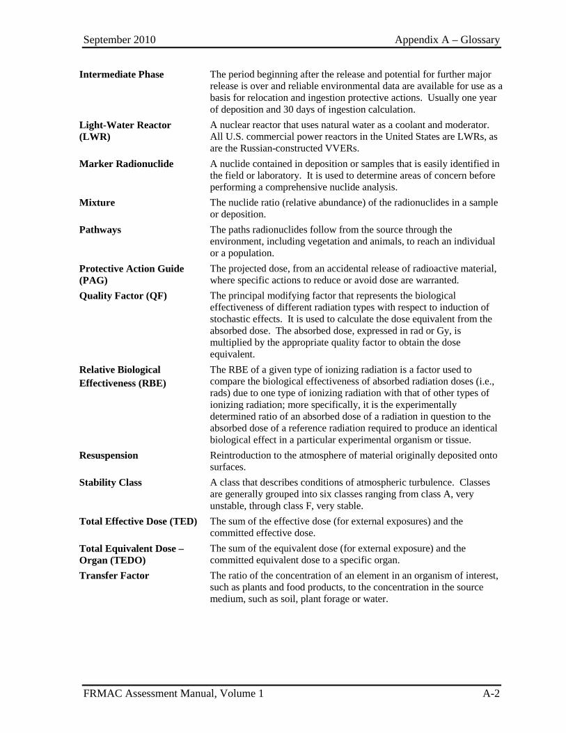
September 2010 Appendix A – Glossary
FRMAC Assessment Manual, Volume 1 A-2
Intermediate Phase The period beginning after the release and potential for further major release is over and reliable environmental data are available for use as a basis for relocation and ingestion protective actions. Usually one year of deposition and 30 days of ingestion calculation.
Light-Water Reactor (LWR)
A nuclear reactor that uses natural water as a coolant and moderator. All U.S. commercial power reactors in the United States are LWRs, as are the Russian-constructed VVERs.
Marker Radionuclide A nuclide contained in deposition or samples that is easily identified in the field or laboratory. It is used to determine areas of concern before performing a comprehensive nuclide analysis.
Mixture The nuclide ratio (relative abundance) of the radionuclides in a sample or deposition.
Pathways The paths radionuclides follow from the source through the environment, including vegetation and animals, to reach an individual or a population.
Protective Action Guide (PAG)
The projected dose, from an accidental release of radioactive material, where specific actions to reduce or avoid dose are warranted.
Quality Factor (QF) The principal modifying factor that represents the biological effectiveness of different radiation types with respect to induction of stochastic effects. It is used to calculate the dose equivalent from the absorbed dose. The absorbed dose, expressed in rad or Gy, is multiplied by the appropriate quality factor to obtain the dose equivalent.
Relative Biological Effectiveness (RBE)
The RBE of a given type of ionizing radiation is a factor used to compare the biological effectiveness of absorbed radiation doses (i.e., rads) due to one type of ionizing radiation with that of other types of ionizing radiation; more specifically, it is the experimentally determined ratio of an absorbed dose of a radiation in question to the absorbed dose of a reference radiation required to produce an identical biological effect in a particular experimental organism or tissue.
Resuspension Reintroduction to the atmosphere of material originally deposited onto surfaces.
Stability Class A class that describes conditions of atmospheric turbulence. Classes are generally grouped into six classes ranging from class A, very unstable, through class F, very stable.
Total Effective Dose (TED) The sum of the effective dose (for external exposures) and the committed effective dose.
Total Equivalent Dose – Organ (TEDO)
The sum of the equivalent dose (for external exposure) and the committed equivalent dose to a specific organ.
Transfer Factor The ratio of the concentration of an element in an organism of interest, such as plants and food products, to the concentration in the source medium, such as soil, plant forage or water.
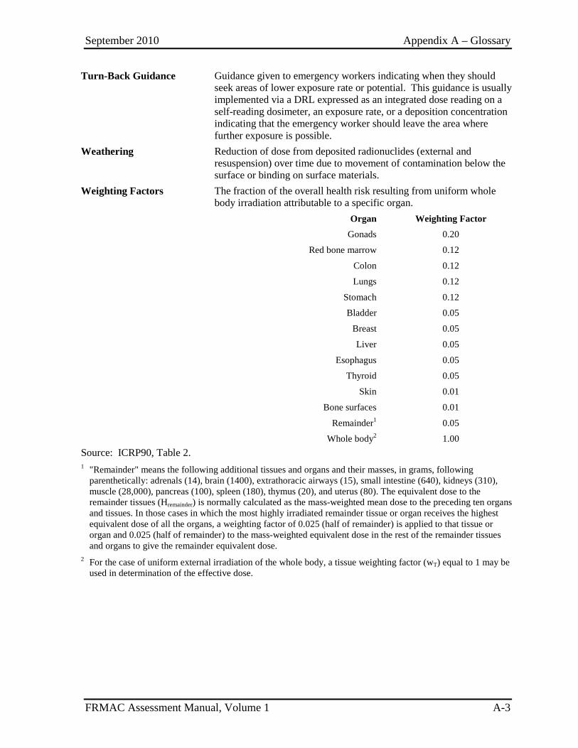
September 2010 Appendix A – Glossary
FRMAC Assessment Manual, Volume 1 A-3
Turn-Back Guidance Guidance given to emergency workers indicating when they should seek areas of lower exposure rate or potential. This guidance is usually implemented via a DRL expressed as an integrated dose reading on a self-reading dosimeter, an exposure rate, or a deposition concentration indicating that the emergency worker should leave the area where further exposure is possible.
Weathering Reduction of dose from deposited radionuclides (external and resuspension) over time due to movement of contamination below the surface or binding on surface materials.
Weighting Factors The fraction of the overall health risk resulting from uniform whole body irradiation attributable to a specific organ.
Organ Weighting Factor
Gonads 0.20
Red bone marrow 0.12
Colon 0.12
Lungs 0.12
Stomach 0.12
Bladder 0.05
Breast 0.05
Liver 0.05
Esophagus 0.05
Thyroid 0.05
Skin 0.01
Bone surfaces 0.01
Remainder1 0.05
Whole body2 1.00 Source: ICRP90, Table 2. 1 "Remainder" means the following additional tissues and organs and their masses, in grams, following
parenthetically: adrenals (14), brain (1400), extrathoracic airways (15), small intestine (640), kidneys (310), muscle (28,000), pancreas (100), spleen (180), thymus (20), and uterus (80). The equivalent dose to the remainder tissues (Hremainder) is normally calculated as the mass-weighted mean dose to the preceding ten organs and tissues. In those cases in which the most highly irradiated remainder tissue or organ receives the highest equivalent dose of all the organs, a weighting factor of 0.025 (half of remainder) is applied to that tissue or organ and 0.025 (half of remainder) to the mass-weighted equivalent dose in the rest of the remainder tissues and organs to give the remainder equivalent dose.
2 For the case of uniform external irradiation of the whole body, a tissue weighting factor (wT) equal to 1 may be used in determination of the effective dose.
September 2010 Appendix A – Glossary
FRMAC Assessment Manual, Volume 1 A-4
This page intentionally left blank.
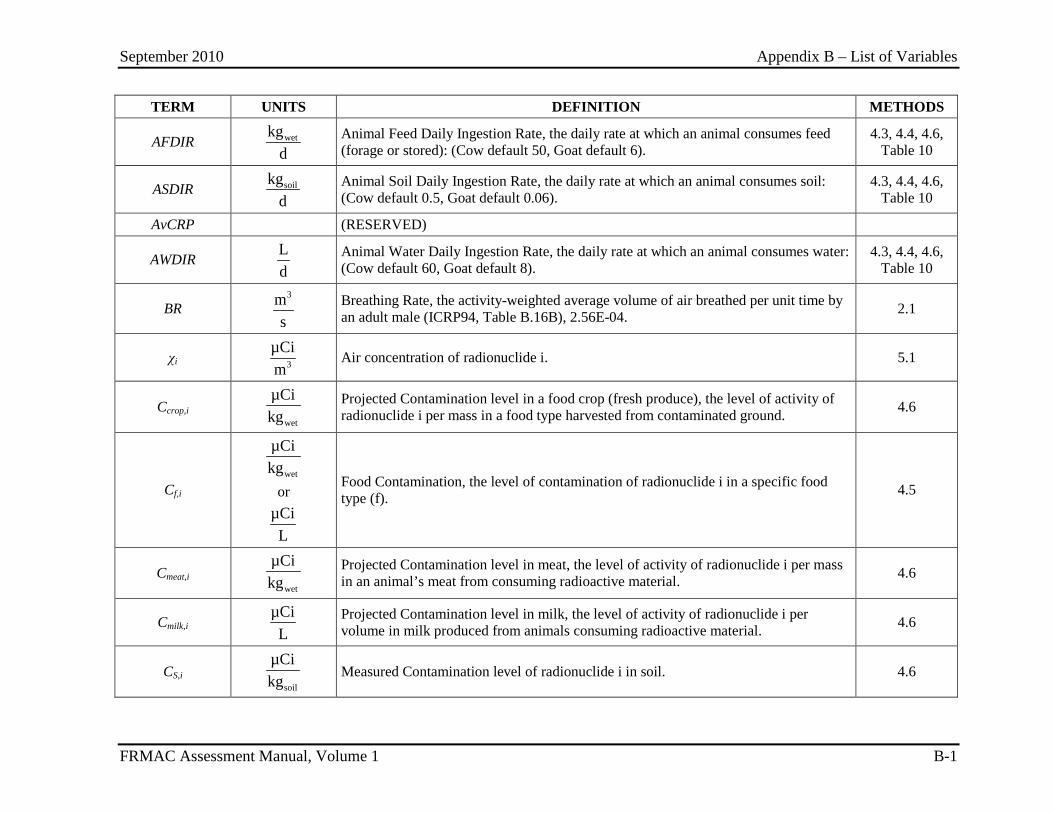
September 2010 Appendix B – List of Variables
FRMAC Assessment Manual, Volume 1 B-1
TERM UNITS DEFINITION METHODS
AFDIR wetkgd
Animal Feed Daily Ingestion Rate, the daily rate at which an animal consumes feed (forage or stored): (Cow default 50, Goat default 6).
4.3, 4.4, 4.6, Table 10
ASDIR soilkgd
Animal Soil Daily Ingestion Rate, the daily rate at which an animal consumes soil: (Cow default 0.5, Goat default 0.06).
4.3, 4.4, 4.6, Table 10
AvCRP (RESERVED)
AWDIR Ld
Animal Water Daily Ingestion Rate, the daily rate at which an animal consumes water: (Cow default 60, Goat default 8).
4.3, 4.4, 4.6, Table 10
BR 3m
s Breathing Rate, the activity-weighted average volume of air breathed per unit time by
an adult male (ICRP94, Table B.16B), 2.56E-04. 2.1
χi 3µCim
Air concentration of radionuclide i. 5.1
Ccrop,i wet
µCikg
Projected Contamination level in a food crop (fresh produce), the level of activity of radionuclide i per mass in a food type harvested from contaminated ground. 4.6
Cf,i wet
µCikg
or µCiL
Food Contamination, the level of contamination of radionuclide i in a specific food type (f). 4.5
Cmeat,i wet
µCikg
Projected Contamination level in meat, the level of activity of radionuclide i per mass in an animal’s meat from consuming radioactive material. 4.6
Cmilk,i µCiL
Projected Contamination level in milk, the level of activity of radionuclide i per volume in milk produced from animals consuming radioactive material. 4.6
CS,i soil
µCikg
Measured Contamination level of radionuclide i in soil. 4.6
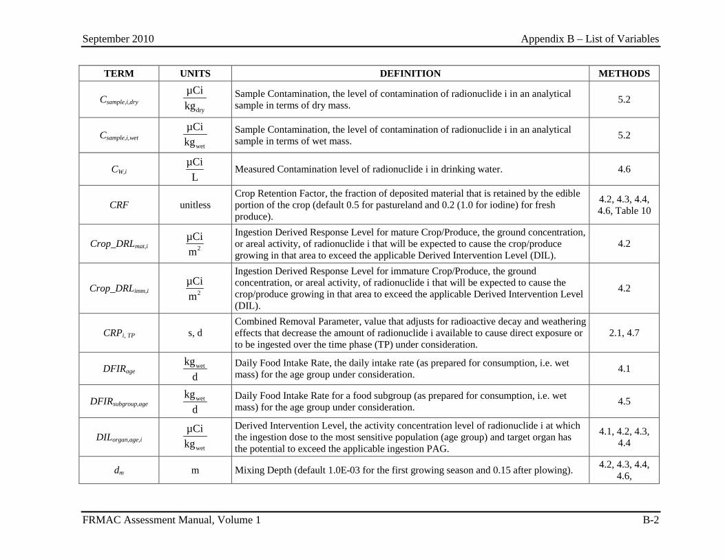
September 2010 Appendix B – List of Variables
FRMAC Assessment Manual, Volume 1 B-2
TERM UNITS DEFINITION METHODS
Csample,i,dry dry
µCikg
Sample Contamination, the level of contamination of radionuclide i in an analytical sample in terms of dry mass. 5.2
Csample,i,wet wet
µCikg
Sample Contamination, the level of contamination of radionuclide i in an analytical sample in terms of wet mass. 5.2
CW,i µCiL
Measured Contamination level of radionuclide i in drinking water. 4.6
CRF unitless Crop Retention Factor, the fraction of deposited material that is retained by the edible portion of the crop (default 0.5 for pastureland and 0.2 (1.0 for iodine) for fresh produce).
4.2, 4.3, 4.4, 4.6, Table 10
Crop_DRLmat,i 2µCim
Ingestion Derived Response Level for mature Crop/Produce, the ground concentration, or areal activity, of radionuclide i that will be expected to cause the crop/produce growing in that area to exceed the applicable Derived Intervention Level (DIL).
4.2
Crop_DRLimm,i 2µCim
Ingestion Derived Response Level for immature Crop/Produce, the ground concentration, or areal activity, of radionuclide i that will be expected to cause the crop/produce growing in that area to exceed the applicable Derived Intervention Level (DIL).
4.2
CRPi, TP s, d Combined Removal Parameter, value that adjusts for radioactive decay and weathering effects that decrease the amount of radionuclide i available to cause direct exposure or to be ingested over the time phase (TP) under consideration.
2.1, 4.7
DFIRage wetkgd
Daily Food Intake Rate, the daily intake rate (as prepared for consumption, i.e. wet mass) for the age group under consideration. 4.1
DFIRsubgroup,age wetkgd
Daily Food Intake Rate for a food subgroup (as prepared for consumption, i.e. wet mass) for the age group under consideration. 4.5
DILorgan,age,i wet
µCikg
Derived Intervention Level, the activity concentration level of radionuclide i at which the ingestion dose to the most sensitive population (age group) and target organ has the potential to exceed the applicable ingestion PAG.
4.1, 4.2, 4.3, 4.4
dm m Mixing Depth (default 1.0E-03 for the first growing season and 0.15 after plowing). 4.2, 4.3, 4.4, 4.6,

September 2010 Appendix B – List of Variables
FRMAC Assessment Manual, Volume 1 B-3
TERM UNITS DEFINITION METHODS
Dp_DRLα,tn α2
μCim
Deposition Alpha Derived Response Level, the areal alpha activity of the mixture, at time tn (time of measurement, prediction or evaluation), at which the dose from all radionuclides in a deposition mixture would result in a dose equal to the PAG for the time phase under consideration.
2.3
Dp_DRLβ-,tn β2
μCim
Deposition Beta Derived Response Level, the areal beta activity of the mixture, at time tn (time of measurement, prediction or evaluation), at which the dose from all radionuclides in a deposition mixture would result in a dose equal to the PAG for the time phase under consideration.
2.4
Dp_DRLDR, E, tn mrem
hr
Deposition Dose Rate Derived Response Level, the external dose rate, at time tn, at which the dose from all radionuclides in a deposition mixture would result in a dose equal to the PAG for the time phase under consideration.
2.2
Dp_DRLorgan,i,tn 2µCim
Deposition Derived Response Level, the areal activity (radioactivity per unit area) at time tn of radionuclide i, at which the dose to the organ of interest from all radionuclides in a deposition mixture would result in a dose equal to the PAG for the time phase under consideration.
2.1, 2.3, 2.4
Dp_DRLXR, E,tn mRhr
Deposition Exposure Rate Derived Response Level, the external exposure rate at time tn at which the dose from all radionuclides in a deposition mixture would result in a dose to the whole body (E) equal to the PAG for the time phase under consideration.
2.2, 2.5
Dpi 2µCim
Deposition of radionuclide i 5.1
Dpi,tn 2µCim
Deposition, the measured or predicted areal activity of radionuclide i per unit area of ground at time tn.
2.1, 2.5, 3.2, 4.6
Dpi (m) 2µCim
Deposition of the marker radionuclide. 2.1, 4.6
Dp_PPDDR,E,TP mrem Deposition Dose Rate Projected Public Dose, the projected dose to the whole body (E), over the time phase (TP) under consideration from a measured external dose rate. 2.5
Dp_PPDDp,E,TP mrem Deposition Projected Public Dose, the projected dose to the whole body (E), over the time phase (TP) under consideration from a deposition of radioactive material. 2.5
DRCFskin,i,TP (RESERVED)
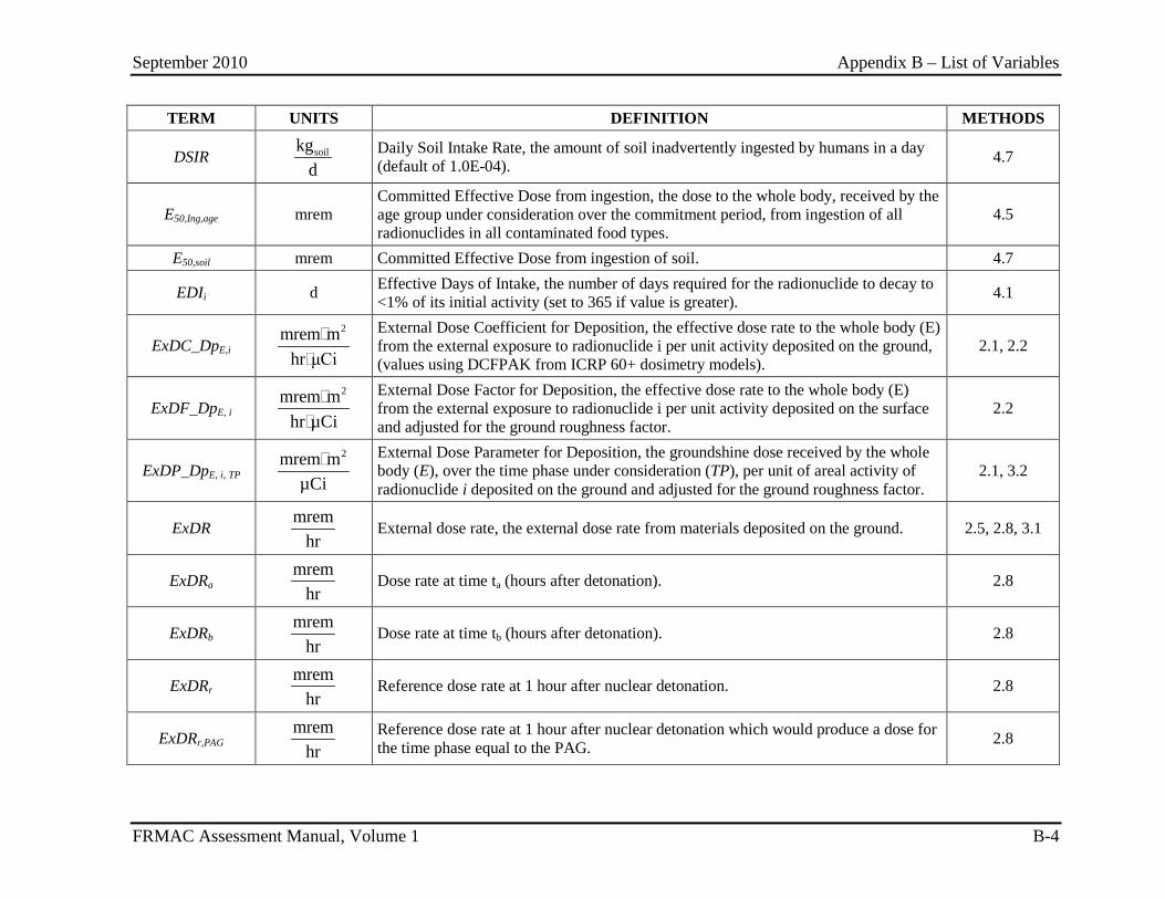
September 2010 Appendix B – List of Variables
FRMAC Assessment Manual, Volume 1 B-4
TERM UNITS DEFINITION METHODS
DSIR soilkgd
Daily Soil Intake Rate, the amount of soil inadvertently ingested by humans in a day (default of 1.0E-04). 4.7
E50,Ing,age mrem Committed Effective Dose from ingestion, the dose to the whole body, received by the age group under consideration over the commitment period, from ingestion of all radionuclides in all contaminated food types.
4.5
E50,soil mrem Committed Effective Dose from ingestion of soil. 4.7
EDIi d Effective Days of Intake, the number of days required for the radionuclide to decay to <1% of its initial activity (set to 365 if value is greater). 4.1
ExDC_DpE,i 2mrem m
hr μCi
External Dose Coefficient for Deposition, the effective dose rate to the whole body (E) from the external exposure to radionuclide i per unit activity deposited on the ground, (values using DCFPAK from ICRP 60+ dosimetry models).
2.1, 2.2
ExDF_DpE, i 2mrem m
hr µCi
External Dose Factor for Deposition, the effective dose rate to the whole body (E) from the external exposure to radionuclide i per unit activity deposited on the surface and adjusted for the ground roughness factor.
2.2
ExDP_DpE, i, TP 2mrem m
µCi
External Dose Parameter for Deposition, the groundshine dose received by the whole body (E), over the time phase under consideration (TP), per unit of areal activity of radionuclide i deposited on the ground and adjusted for the ground roughness factor.
2.1, 3.2
ExDR mrem
hr External dose rate, the external dose rate from materials deposited on the ground. 2.5, 2.8, 3.1
ExDRa mrem
hr Dose rate at time ta (hours after detonation). 2.8
ExDRb mrem
hr Dose rate at time tb (hours after detonation). 2.8
ExDRr mrem
hr Reference dose rate at 1 hour after nuclear detonation. 2.8
ExDRr,PAG mrem
hr
Reference dose rate at 1 hour after nuclear detonation which would produce a dose for the time phase equal to the PAG. 2.8
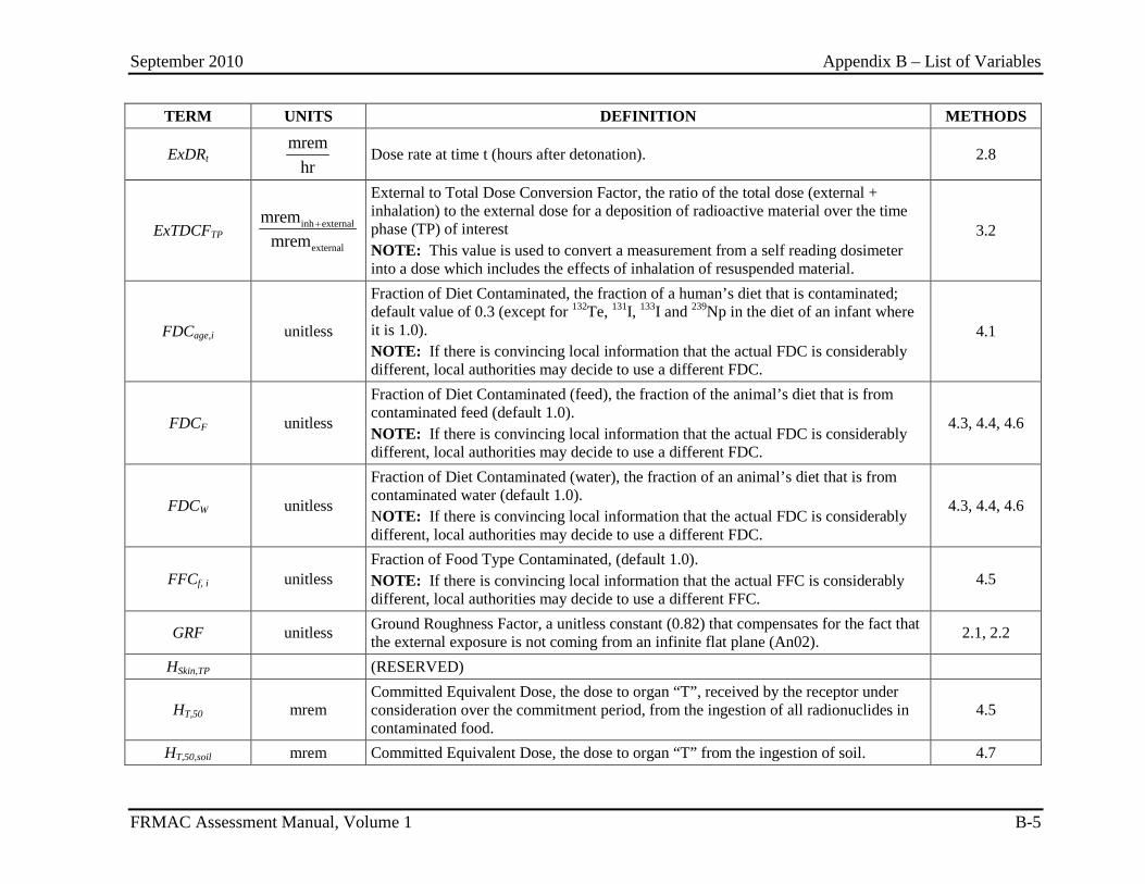
September 2010 Appendix B – List of Variables
FRMAC Assessment Manual, Volume 1 B-5
TERM UNITS DEFINITION METHODS
ExDRt mrem
hr Dose rate at time t (hours after detonation). 2.8
ExTDCFTP inh external
external
mremmrem
+
External to Total Dose Conversion Factor, the ratio of the total dose (external + inhalation) to the external dose for a deposition of radioactive material over the time phase (TP) of interest NOTE: This value is used to convert a measurement from a self reading dosimeter into a dose which includes the effects of inhalation of resuspended material.
3.2
FDCage,i unitless
Fraction of Diet Contaminated, the fraction of a human’s diet that is contaminated; default value of 0.3 (except for 132Te, 131I, 133I and 239Np in the diet of an infant where it is 1.0). NOTE: If there is convincing local information that the actual FDC is considerably different, local authorities may decide to use a different FDC.
4.1
FDCF unitless
Fraction of Diet Contaminated (feed), the fraction of the animal’s diet that is from contaminated feed (default 1.0). NOTE: If there is convincing local information that the actual FDC is considerably different, local authorities may decide to use a different FDC.
4.3, 4.4, 4.6
FDCW unitless
Fraction of Diet Contaminated (water), the fraction of an animal’s diet that is from contaminated water (default 1.0). NOTE: If there is convincing local information that the actual FDC is considerably different, local authorities may decide to use a different FDC.
4.3, 4.4, 4.6
FFCf, i unitless Fraction of Food Type Contaminated, (default 1.0). NOTE: If there is convincing local information that the actual FFC is considerably different, local authorities may decide to use a different FFC.
4.5
GRF unitless Ground Roughness Factor, a unitless constant (0.82) that compensates for the fact that the external exposure is not coming from an infinite flat plane (An02). 2.1, 2.2
HSkin,TP (RESERVED)
HT,50 mrem Committed Equivalent Dose, the dose to organ “T”, received by the receptor under consideration over the commitment period, from the ingestion of all radionuclides in contaminated food.
4.5
HT,50,soil mrem Committed Equivalent Dose, the dose to organ “T” from the ingestion of soil. 4.7
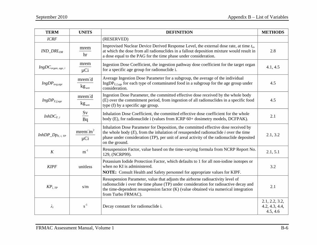
September 2010 Appendix B – List of Variables
FRMAC Assessment Manual, Volume 1 B-6
TERM UNITS DEFINITION METHODS ICRF (RESERVED)
IND_DRLDR mrem
hr
Improvised Nuclear Device Derived Response Level, the external dose rate, at time tn, at which the dose from all radionuclides in a fallout deposition mixture would result in a dose equal to the PAG for the time phase under consideration.
2.8
IngDCorgan, age, i mremµCi
Ingestion Dose Coefficient, the ingestion pathway dose coefficient for the target organ for a specific age group for radionuclide i. 4.1, 4.5
IngDPavg,age wet
mrem dkg
Average Ingestion Dose Parameter for a subgroup, the average of the individual IngDPE,f,age for each type of contaminated food in a subgroup for the age group under consideration.
4.5
IngDPE,f,age wet
mrem dkg
Ingestion Dose Parameter, the committed effective dose received by the whole body (E) over the commitment period, from ingestion of all radionuclides in a specific food type (f) by a specific age group.
4.5
InhDCE ,i SvBq
Inhalation Dose Coefficient, the committed effective dose coefficient for the whole body (E), for radionuclide i (values from ICRP 60+ dosimetry models, DCFPAK). 2.1
InhDP_DpE, i, TP 2mrem m
µCi
Inhalation Dose Parameter for Deposition, the committed effective dose received by the whole body (E), from the inhalation of resuspended radionuclide i over the time phase under consideration (TP), per unit of areal activity of the radionuclide deposited on the ground.
2.1, 3.2
K m-1 Resuspension Factor, value based on the time-varying formula from NCRP Report No. 129, (NCRP99). 2.1, 5.1
KIPF unitless Potassium Iodide Protection Factor, which defaults to 1 for all non-iodine isotopes or when no KI is administered. NOTE: Consult Health and Safety personnel for appropriate values for KIPF.
3.2
KPi, TP s/m
Resuspension Parameter, value that adjusts the airborne radioactivity level of radionuclide i over the time phase (TP) under consideration for radioactive decay and the time-dependent resuspension factor (K) (value obtained via numerical integration from Turbo FRMAC).
2.1
λi s-1 Decay constant for radionuclide i. 2.1, 2.2, 3.2, 4.2, 4.3, 4.4,
4.5, 4.6
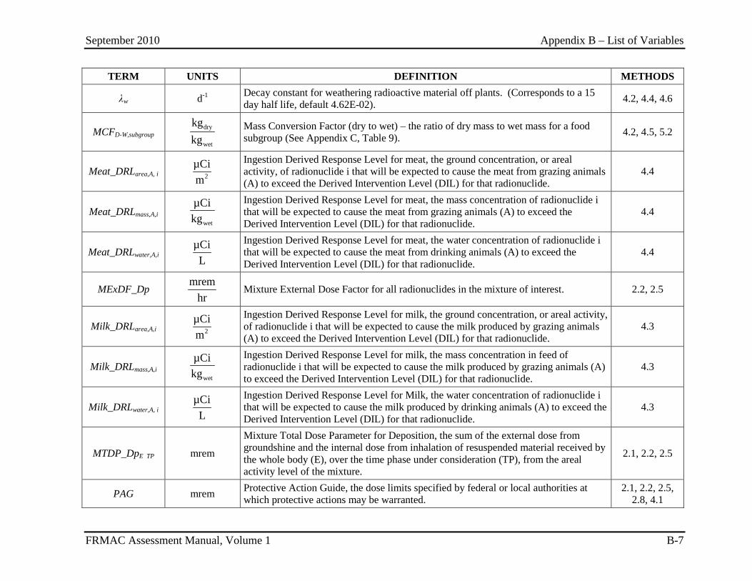
September 2010 Appendix B – List of Variables
FRMAC Assessment Manual, Volume 1 B-7
TERM UNITS DEFINITION METHODS
λw d-1 Decay constant for weathering radioactive material off plants. (Corresponds to a 15 day half life, default 4.62E-02). 4.2, 4.4, 4.6
MCFD-W,subgroup dry
wet
kgkg
Mass Conversion Factor (dry to wet) – the ratio of dry mass to wet mass for a food subgroup (See Appendix C, Table 9). 4.2, 4.5, 5.2
Meat_DRLarea,A, i 2µCim
Ingestion Derived Response Level for meat, the ground concentration, or areal activity, of radionuclide i that will be expected to cause the meat from grazing animals (A) to exceed the Derived Intervention Level (DIL) for that radionuclide.
4.4
Meat_DRLmass,A,i wet
µCikg
Ingestion Derived Response Level for meat, the mass concentration of radionuclide i that will be expected to cause the meat from grazing animals (A) to exceed the Derived Intervention Level (DIL) for that radionuclide.
4.4
Meat_DRLwater,A,i µCiL
Ingestion Derived Response Level for meat, the water concentration of radionuclide i that will be expected to cause the meat from drinking animals (A) to exceed the Derived Intervention Level (DIL) for that radionuclide.
4.4
MExDF_Dp mrem
hr Mixture External Dose Factor for all radionuclides in the mixture of interest. 2.2, 2.5
Milk_DRLarea,A,i 2µCim
Ingestion Derived Response Level for milk, the ground concentration, or areal activity, of radionuclide i that will be expected to cause the milk produced by grazing animals (A) to exceed the Derived Intervention Level (DIL) for that radionuclide.
4.3
Milk_DRLmass,A,i wet
µCikg
Ingestion Derived Response Level for milk, the mass concentration in feed of radionuclide i that will be expected to cause the milk produced by grazing animals (A) to exceed the Derived Intervention Level (DIL) for that radionuclide.
4.3
Milk_DRLwater,A, i µCiL
Ingestion Derived Response Level for Milk, the water concentration of radionuclide i that will be expected to cause the milk produced by drinking animals (A) to exceed the Derived Intervention Level (DIL) for that radionuclide.
4.3
MTDP_DpE TP mrem
Mixture Total Dose Parameter for Deposition, the sum of the external dose from groundshine and the internal dose from inhalation of resuspended material received by the whole body (E), over the time phase under consideration (TP), from the areal activity level of the mixture.
2.1, 2.2, 2.5
PAG mrem Protective Action Guide, the dose limits specified by federal or local authorities at which protective actions may be warranted.
2.1, 2.2, 2.5, 2.8, 4.1
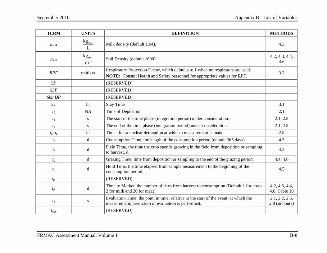
September 2010 Appendix B – List of Variables
FRMAC Assessment Manual, Volume 1 B-8
TERM UNITS DEFINITION METHODS
ρmilk wetkgL
Milk density (default 1.04). 4.3
ρsoil soil3
kgm
Soil Density (default 1600). 4.2, 4.3, 4.4, 4.6
RPF unitless Respiratory Protection Factor, which defaults to 1 when no respirators are used. NOTE: Consult Health and Safety personnel for appropriate values for RPF.
3.2
SF (RESERVED) SSF (RESERVED)
SkinDP (RESERVED) ST hr Stay Time 3.1 t0 NA Time of Deposition 2.1 t1 s The start of the time phase (integration period) under consideration. 2.1, 2.8 t2 s The end of the time phase (integration period) under consideration. 2.1, 2.8
ta, tb hr Time after a nuclear detonation at which a measurement is made. 2.8 tc d Consumption Time, the length of the consumption period (default 365 days). 4.5
tf d Field Time, the time the crop spends growing in the field from deposition or sampling to harvest, d; 4.2
tg d Grazing Time, time from deposition or sampling to the end of the grazing period. 4.4, 4.6
th d Hold Time, the time elapsed from sample measurement to the beginning of the consumption period. 4.5
tIn (RESERVED)
tm d Time to Market, the number of days from harvest to consumption (Default 1 for crops, 2 for milk and 20 for meat).
4.2, 4.3, 4.4, 4.6, Table 10
tn s Evaluation Time, the point in time, relative to the start of the event, at which the measurement, prediction or evaluation is performed.
2.1, 2.2, 2.5, 2.8 (in hours)
tOut (RESERVED)
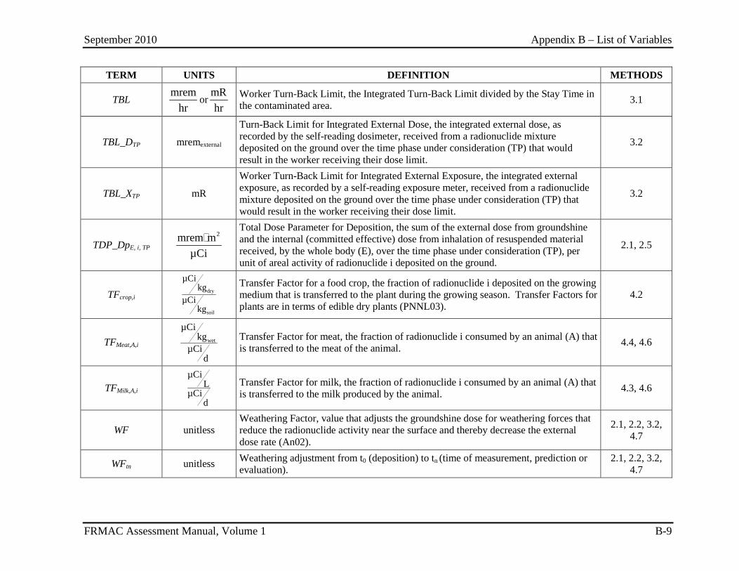
September 2010 Appendix B – List of Variables
FRMAC Assessment Manual, Volume 1 B-9
TERM UNITS DEFINITION METHODS
TBL mrem
hror
mRhr
Worker Turn-Back Limit, the Integrated Turn-Back Limit divided by the Stay Time in the contaminated area. 3.1
TBL_DTP mremexternal
Turn-Back Limit for Integrated External Dose, the integrated external dose, as recorded by the self-reading dosimeter, received from a radionuclide mixture deposited on the ground over the time phase under consideration (TP) that would result in the worker receiving their dose limit.
3.2
TBL_XTP mR
Worker Turn-Back Limit for Integrated External Exposure, the integrated external exposure, as recorded by a self-reading exposure meter, received from a radionuclide mixture deposited on the ground over the time phase under consideration (TP) that would result in the worker receiving their dose limit.
3.2
TDP_DpE, i, TP 2mrem m
µCi
Total Dose Parameter for Deposition, the sum of the external dose from groundshine and the internal (committed effective) dose from inhalation of resuspended material received, by the whole body (E), over the time phase under consideration (TP), per unit of areal activity of radionuclide i deposited on the ground.
2.1, 2.5
TFcrop,i dry
soil
µCikg
µCikg
Transfer Factor for a food crop, the fraction of radionuclide i deposited on the growing medium that is transferred to the plant during the growing season. Transfer Factors for plants are in terms of edible dry plants (PNNL03).
4.2
TFMeat,A,i wet
µCikg
µCid
Transfer Factor for meat, the fraction of radionuclide i consumed by an animal (A) that is transferred to the meat of the animal. 4.4, 4.6
TFMilk,A,i µCi
LµCi
d
Transfer Factor for milk, the fraction of radionuclide i consumed by an animal (A) that is transferred to the milk produced by the animal. 4.3, 4.6
WF unitless Weathering Factor, value that adjusts the groundshine dose for weathering forces that reduce the radionuclide activity near the surface and thereby decrease the external dose rate (An02).
2.1, 2.2, 3.2, 4.7
WFtn unitless Weathering adjustment from t0 (deposition) to tn (time of measurement, prediction or evaluation).
2.1, 2.2, 3.2, 4.7
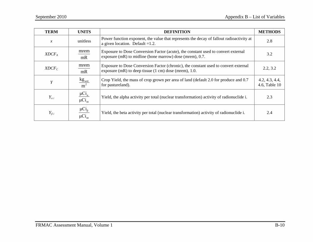
September 2010 Appendix B – List of Variables
FRMAC Assessment Manual, Volume 1 B-10
TERM UNITS DEFINITION METHODS
x unitless Power function exponent, the value that represents the decay of fallout radioactivity at a given location. Default =1.2. 2.8
XDCFA mremmR
Exposure to Dose Conversion Factor (acute), the constant used to convert external exposure (mR) to midline (bone marrow) dose (mrem), 0.7. 3.2
XDCFC mremmR
Exposure to Dose Conversion Factor (chronic), the constant used to convert external exposure (mR) to deep tissue (1 cm) dose (mrem), 1.0. 2.2, 3.2
Y wet2
kgm
Crop Yield, the mass of crop grown per area of land (default 2.0 for produce and 0.7 for pastureland).
4.2, 4.3, 4.4, 4.6, Table 10
Yα i α
nt
μCiμCi
Yield, the alpha activity per total (nuclear transformation) activity of radionuclide i. 2.3
Yβ i β
nt
μCiμCi
Yield, the beta activity per total (nuclear transformation) activity of radionuclide i. 2.4
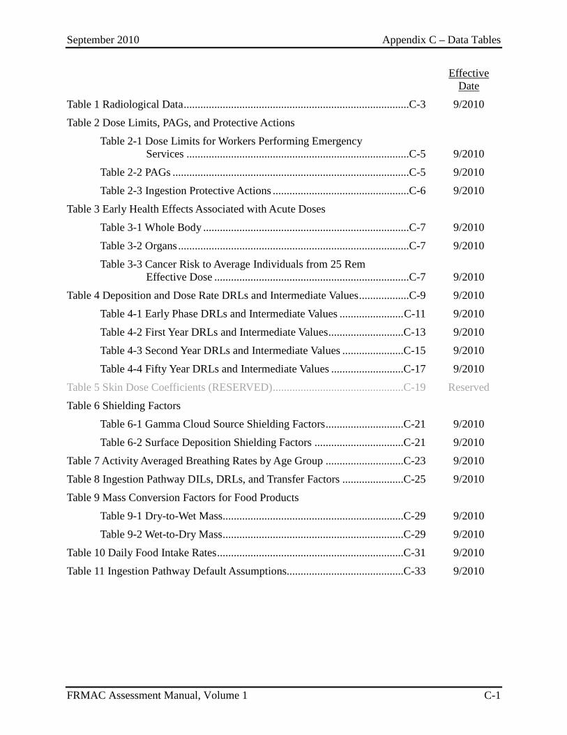
September 2010 Appendix C – Data Tables
FRMAC Assessment Manual, Volume 1 C-1
Effective
Date
Table 1 Radiological Data .................................................................................C-3 9/2010
Table 2 Dose Limits, PAGs, and Protective Actions
Table 2-1 Dose Limits for Workers Performing Emergency Services ................................................................................C-5 9/2010
Table 2-2 PAGs .....................................................................................C-5 9/2010
Table 2-3 Ingestion Protective Actions .................................................C-6 9/2010
Table 3 Early Health Effects Associated with Acute Doses
Table 3-1 Whole Body ..........................................................................C-7 9/2010
Table 3-2 Organs ...................................................................................C-7 9/2010
Table 3-3 Cancer Risk to Average Individuals from 25 Rem Effective Dose ......................................................................C-7 9/2010
Table 4 Deposition and Dose Rate DRLs and Intermediate Values ..................C-9 9/2010
Table 4-1 Early Phase DRLs and Intermediate Values ....................... C-11 9/2010
Table 4-2 First Year DRLs and Intermediate Values ...........................C-13 9/2010
Table 4-3 Second Year DRLs and Intermediate Values ......................C-15 9/2010
Table 4-4 Fifty Year DRLs and Intermediate Values ..........................C-17 9/2010
Table 5 Skin Dose Coefficients (RESERVED) ...............................................C-19 Reserved
Table 6 Shielding Factors
Table 6-1 Gamma Cloud Source Shielding Factors ............................C-21 9/2010
Table 6-2 Surface Deposition Shielding Factors ................................C-21 9/2010
Table 7 Activity Averaged Breathing Rates by Age Group ............................C-23 9/2010
Table 8 Ingestion Pathway DILs, DRLs, and Transfer Factors ......................C-25 9/2010
Table 9 Mass Conversion Factors for Food Products
Table 9-1 Dry-to-Wet Mass .................................................................C-29 9/2010
Table 9-2 Wet-to-Dry Mass .................................................................C-29 9/2010
Table 10 Daily Food Intake Rates ...................................................................C-31 9/2010
Table 11 Ingestion Pathway Default Assumptions..........................................C-33 9/2010
September 2010 Appendix C – Data Tables
FRMAC Assessment Manual, Volume 1 C-2
This page intentionally left blank.
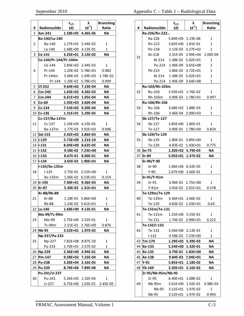
September 2010 Appendix C – Table 1 – Radiological Data
FRMAC Assessment Manual, Volume 1 C-3
# Radionuclide t1/2 (d)
λ (d-1)
Branching Ratio
# Radionuclide
t1/2 (d)
λ (d-1)
Branching Ratio
1 Am-241 1.58E+05 4.36E-06 NA
31
Ra-226/Rn-222…
2 Ba-140/La-140 Ra-226 5.84E+05 1.19E-06 1 Ba-140 1.27E+01 5.44E-02 1 Rn-222 3.82E+00 1.81E-01 1 La-140 1.68E+00 4.13E-01 1 Po-218 2.12E-03 3.27E+02 1
3 Ce-141 3.25E+01 2.13E-02 NA At-218 2.31E-05 2.99E+04 2.00E-04
4
Ce-144/Pr-144/Pr-144m Bi-214 1.38E-02 5.02E+01 1 Ce-144 2.84E+02 2.44E-03 1 Po-214 1.90E-09 3.65E+08 1 Pr-144 1.20E-02 5.78E+01 0.982 Pb-214 1.86E-02 3.72E+01 1 Pr-144m 5.00E-03 1.39E+02 1.78E-02 Bi-214 1.38E-02 5.02E+01 1 Pr-144 1.20E-02 5.78E+01 0.999 Po-214 1.90E-09 3.64E+08 1
5 Cf-252 9.64E+02 7.19E-04 NA 32
Ru-103/Rh-103m 6 Cm-242 1.63E+02 4.26E-03 NA Ru-103 3.93E+01 1.76E-02 1 7 Cm-244 6.61E+03 1.05E-04 NA Rh-103m 3.90E-02 1.78E+01 0.997 8 Co-60 1.93E+03 3.60E-04 NA
33 Ru-106/Rh-106
9 Cs-134 7.53E+02 9.20E-04 NA Ru-106 3.68E+02 1.88E-03 1 10 Cs-136 1.31E+01 5.29E-02 NA Rh-106 3.46E-04 2.00E+03 1
11 Cs-137/Ba-137m
34 Sb-127/Te-127
Cs-137 1.10E+04 6.33E-05 1 Sb-127 3.85E+00 1.80E-01 1 Ba-137m 1.77E-03 3.91E+02 0.946 Te-127 3.90E-01 1.78E+00 0.824
12 Gd-153 2.42E+02 2.86E-03 NA 35
Sb-129/Te-129 13 I-129 5.73E+09 1.21E-10 NA Sb-129 1.80E-01 3.85E+00 1 14 I-131 8.04E+00 8.62E-02 NA Te-129 4.83E-02 1.43E+01 0.775 15 I-132 9.58E-02 7.23E+00 NA 36 Se-75 1.20E+02 5.79E-03 NA 16 I-133 8.67E-01 8.00E-01 NA 37 Sr-89 5.05E+01 1.37E-02 NA 17 I-134 3.65E-02 1.90E+01 NA
38 Sr-90/Y-90
18 I-135/Xe-135m Sr-90 1.06E+04 6.52E-05 1 I-135 2.75E-01 2.52E+00 1 Y-90 2.67E+00 2.60E-01 1 Xe-135m 1.06E-02 6.53E+01 0.154
39 Sr-91/Y-91m
19 Ir-192 7.40E+01 9.36E-03 NA Sr-91 3.96E-01 1.75E+00 1 20 Kr-87 5.30E-02 1.31E+01 NA Y-91m 3.45E-02 2.01E+01 0.578
21 Kr-88/Rb-88
40 Te-129m/Te-129
Kr-88 1.18E-01 5.86E+00 1 Te-129m 3.36E+01 2.06E-02 1 Rb-88 1.24E-02 5.61E+01 1 Te-129 4.83E-02 1.43E+01 0.65
22 La-140 1.68E+00 4.13E-01 NA 41
Te-131m/Te-131
23 Mo-99/Tc-99m Te-131m 1.25E+00 5.55E-01 1 Mo-99 2.75E+00 2.52E-01 1 Te-131 1.74E-02 3.99E+01 0.222 Tc-99m 2.51E-01 2.76E+00 0.876
42 Te-132/I-132
24 Nb-95 3.52E+01 1.97E-02 NA Te-132 3.26E+00 2.13E-01 1
25 Np-237/Pa-233 I-132 9.58E-02 7.23E+00 1 Np-237 7.82E+08 8.87E-10 1 43 Tm-170 1.29E+02 5.39E-03 NA Pa-233 2.70E+01 2.57E-02 1 44 Xe-133 5.24E+00 1.32E-01 NA
26 Np-239 2.36E+00 2.94E-01 NA 45 Xe-135 3.79E-01 1.83E+00 NA 27 Pm-147 9.58E+02 7.23E-04 NA 46 Xe-138 9.84E-03 7.04E+01 NA 28 Pu-238 3.20E+04 2.16E-05 NA 47 Y-91 5.85E+01 1.18E-02 NA 29 Pu-239 8.79E+06 7.89E-08 NA 48 Yb-169 3.20E+01 2.16E-02 NA
30 Pu-241/U-237
49
Zr-95/Nb-95m/Nb-95 Pu-241 5.26E+03 1.32E-04 1 Zr-95 6.40E+01 1.08E-02 1 U-237 6.75E+00 1.03E-01 2.45E-05 Nb-95m 3.61E+00 1.92E-01 6.98E-03
Nb-95 3.52E+01 1.97E-02 1
Nb-95 3.52E+01 1.97E-02 0.993
September 2010 Appendix C – Table 1 – Radiological Data
FRMAC Assessment Manual, Volume 1 C-4
This page intentionally left blank.
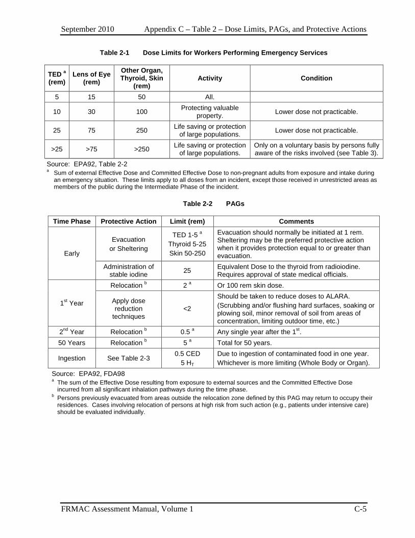
September 2010 Appendix C – Table 2 – Dose Limits, PAGs, and Protective Actions
FRMAC Assessment Manual, Volume 1 C-5
Table 2-1 Dose Limits for Workers Performing Emergency Services
TED a (rem)
Lens of Eye (rem)
Other Organ, Thyroid, Skin
(rem) Activity Condition
5 15 50 All.
10 30 100 Protecting valuable property. Lower dose not practicable.
25 75 250 Life saving or protection of large populations. Lower dose not practicable.
>25 >75 >250 Life saving or protection of large populations.
Only on a voluntary basis by persons fully aware of the risks involved (see Table 3).
Source: EPA92, Table 2-2 a Sum of external Effective Dose and Committed Effective Dose to non-pregnant adults from exposure and intake during
an emergency situation. These limits apply to all doses from an incident, except those received in unrestricted areas as members of the public during the Intermediate Phase of the incident.
Table 2-2 PAGs
Time Phase Protective Action Limit (rem) Comments
Early
Evacuation or Sheltering
TED 1-5 a Thyroid 5-25 Skin 50-250
Evacuation should normally be initiated at 1 rem. Sheltering may be the preferred protective action when it provides protection equal to or greater than evacuation.
Administration of stable iodine 25 Equivalent Dose to the thyroid from radioiodine.
Requires approval of state medical officials.
1st Year
Relocation b 2 a Or 100 rem skin dose.
Apply dose reduction
techniques <2
Should be taken to reduce doses to ALARA. (Scrubbing and/or flushing hard surfaces, soaking or plowing soil, minor removal of soil from areas of concentration, limiting outdoor time, etc.)
2nd Year Relocation b 0.5 a Any single year after the 1st. 50 Years Relocation b 5 a Total for 50 years.
Ingestion See Table 2-3 0.5 CED
5 HT Due to ingestion of contaminated food in one year. Whichever is more limiting (Whole Body or Organ).
Source: EPA92, FDA98 a The sum of the Effective Dose resulting from exposure to external sources and the Committed Effective Dose
incurred from all significant inhalation pathways during the time phase. b Persons previously evacuated from areas outside the relocation zone defined by this PAG may return to occupy their
residences. Cases involving relocation of persons at high risk from such action (e.g., patients under intensive care) should be evaluated individually.
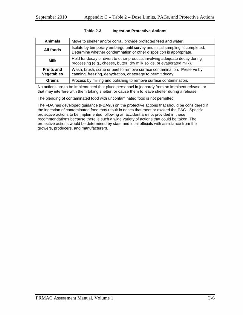
September 2010 Appendix C – Table 2 – Dose Limits, PAGs, and Protective Actions
FRMAC Assessment Manual, Volume 1 C-6
Table 2-3 Ingestion Protective Actions
Animals Move to shelter and/or corral, provide protected feed and water.
All foods Isolate by temporary embargo until survey and initial sampling is completed. Determine whether condemnation or other disposition is appropriate.
Milk Hold for decay or divert to other products involving adequate decay during processing (e.g., cheese, butter, dry milk solids, or evaporated milk).
Fruits and Vegetables
Wash, brush, scrub or peel to remove surface contamination. Preserve by canning, freezing, dehydration, or storage to permit decay.
Grains Process by milling and polishing to remove surface contamination. No actions are to be implemented that place personnel in jeopardy from an imminent release, or that may interfere with them taking shelter, or cause them to leave shelter during a release.
The blending of contaminated food with uncontaminated food is not permitted.
The FDA has developed guidance (FDA98) on the protective actions that should be considered if the ingestion of contaminated food may result in doses that meet or exceed the PAG. Specific protective actions to be implemented following an accident are not provided in these recommendations because there is such a wide variety of actions that could be taken. The protective actions would be determined by state and local officials with assistance from the growers, producers, and manufacturers.
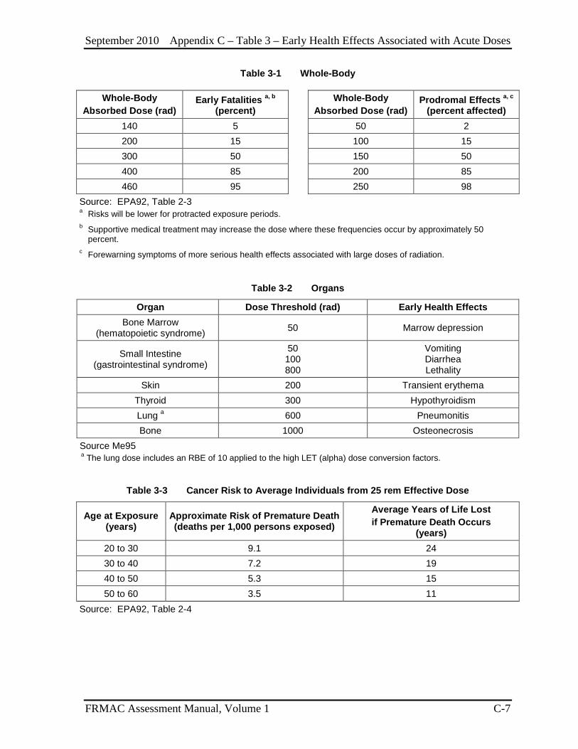
September 2010 Appendix C – Table 3 – Early Health Effects Associated with Acute Doses
FRMAC Assessment Manual, Volume 1 C-7
Table 3-1 Whole-Body
Whole-Body Absorbed Dose (rad)
Early Fatalities a, b (percent)
Whole-Body Absorbed Dose (rad)
Prodromal Effects a, c (percent affected)
140 5 50 2 200 15 100 15 300 50 150 50 400 85 200 85 460 95 250 98
Source: EPA92, Table 2-3 a Risks will be lower for protracted exposure periods. b Supportive medical treatment may increase the dose where these frequencies occur by approximately 50
percent. c Forewarning symptoms of more serious health effects associated with large doses of radiation.
Table 3-2 Organs
Organ Dose Threshold (rad) Early Health Effects Bone Marrow
(hematopoietic syndrome) 50 Marrow depression
Small Intestine (gastrointestinal syndrome)
50 100 800
Vomiting Diarrhea Lethality
Skin 200 Transient erythema Thyroid 300 Hypothyroidism Lung a 600 Pneumonitis Bone 1000 Osteonecrosis
Source Me95 a The lung dose includes an RBE of 10 applied to the high LET (alpha) dose conversion factors.
Table 3-3 Cancer Risk to Average Individuals from 25 rem Effective Dose
Age at Exposure (years)
Approximate Risk of Premature Death (deaths per 1,000 persons exposed)
Average Years of Life Lost if Premature Death Occurs
(years) 20 to 30 9.1 24 30 to 40 7.2 19 40 to 50 5.3 15 50 to 60 3.5 11
Source: EPA92, Table 2-4
September 2010 Appendix C – Table 3 – Early Health Effects Associated with Acute Doses
FRMAC Assessment Manual, Volume 1 C-8
This page intentionally left blank.
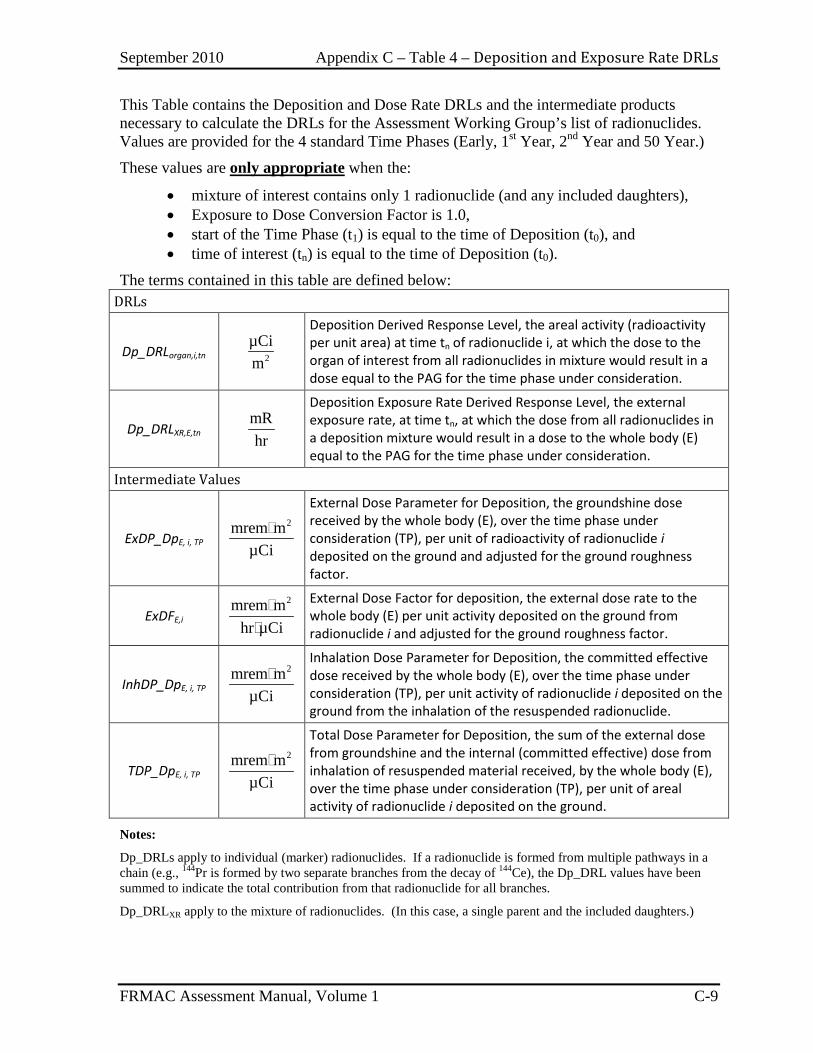
September 2010 Appendix C – Table 4 – Deposition and Exposure Rate DRLs
FRMAC Assessment Manual, Volume 1 C-9
This Table contains the Deposition and Dose Rate DRLs and the intermediate products necessary to calculate the DRLs for the Assessment Working Group’s list of radionuclides. Values are provided for the 4 standard Time Phases (Early, 1st Year, 2nd Year and 50 Year.)
These values are only appropriate when the:
• mixture of interest contains only 1 radionuclide (and any included daughters), • Exposure to Dose Conversion Factor is 1.0, • start of the Time Phase (t1) is equal to the time of Deposition (t0), and • time of interest (tn) is equal to the time of Deposition (t0).
The terms contained in this table are defined below: DRLs
Dp_DRLorgan,i,tn 2µCim
Deposition Derived Response Level, the areal activity (radioactivity per unit area) at time tn of radionuclide i, at which the dose to the organ of interest from all radionuclides in mixture would result in a dose equal to the PAG for the time phase under consideration.
Dp_DRLXR,E,tn mRhr
Deposition Exposure Rate Derived Response Level, the external exposure rate, at time tn, at which the dose from all radionuclides in a deposition mixture would result in a dose to the whole body (E) equal to the PAG for the time phase under consideration.
Intermediate Values
ExDP_DpE, i, TP 2mrem m
µCi
External Dose Parameter for Deposition, the groundshine dose received by the whole body (E), over the time phase under consideration (TP), per unit of radioactivity of radionuclide i deposited on the ground and adjusted for the ground roughness factor.
ExDFE,i 2mrem m
hr µCi
External Dose Factor for deposition, the external dose rate to the whole body (E) per unit activity deposited on the ground from radionuclide i and adjusted for the ground roughness factor.
InhDP_DpE, i, TP 2mrem m
µCi
Inhalation Dose Parameter for Deposition, the committed effective dose received by the whole body (E), over the time phase under consideration (TP), per unit activity of radionuclide i deposited on the ground from the inhalation of the resuspended radionuclide.
TDP_DpE, i, TP 2mrem m
µCi
Total Dose Parameter for Deposition, the sum of the external dose from groundshine and the internal (committed effective) dose from inhalation of resuspended material received, by the whole body (E), over the time phase under consideration (TP), per unit of areal activity of radionuclide i deposited on the ground.
Notes:
Dp_DRLs apply to individual (marker) radionuclides. If a radionuclide is formed from multiple pathways in a chain (e.g., 144Pr is formed by two separate branches from the decay of 144Ce), the Dp_DRL values have been summed to indicate the total contribution from that radionuclide for all branches.
Dp_DRLXR apply to the mixture of radionuclides. (In this case, a single parent and the included daughters.)
September 2010 Appendix C – Table 4 – Deposition and Exposure Rate DRLs
FRMAC Assessment Manual, Volume 1 C-10
This page intentionally left blank.
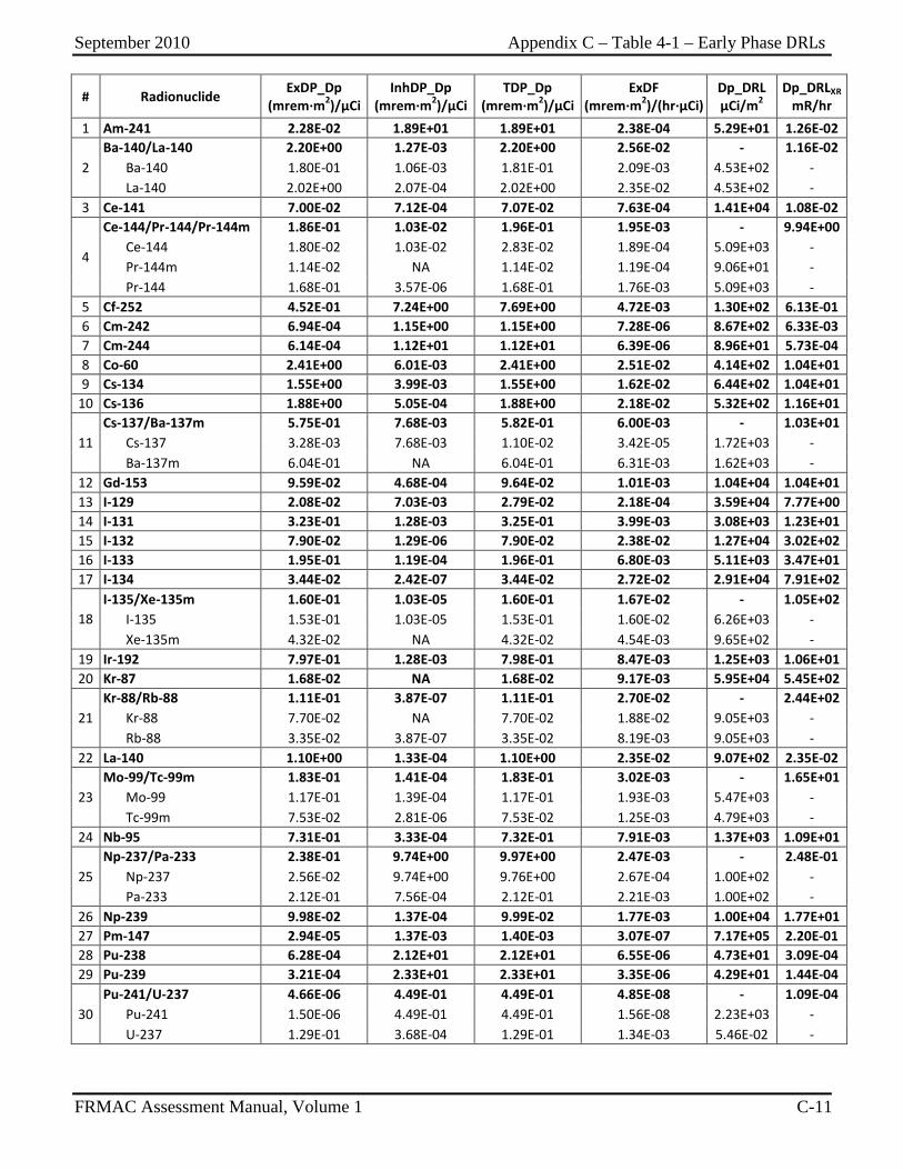
September 2010 Appendix C – Table 4-1 – Early Phase DRLs
FRMAC Assessment Manual, Volume 1 C-11
# Radionuclide ExDP_Dp (mrem∙m2)/µCi
InhDP_Dp (mrem∙m2)/µCi
TDP_Dp (mrem∙m2)/µCi
ExDF (mrem∙m2)/(hr∙µCi)
Dp_DRL µCi/m2
Dp_DRLXR mR/hr
1 Am-241 2.28E-02 1.89E+01 1.89E+01 2.38E-04 5.29E+01 1.26E-02
2 Ba-140/La-140 2.20E+00 1.27E-03 2.20E+00 2.56E-02 - 1.16E-02 Ba-140 1.80E-01 1.06E-03 1.81E-01 2.09E-03 4.53E+02 - La-140 2.02E+00 2.07E-04 2.02E+00 2.35E-02 4.53E+02 -
3 Ce-141 7.00E-02 7.12E-04 7.07E-02 7.63E-04 1.41E+04 1.08E-02
4
Ce-144/Pr-144/Pr-144m 1.86E-01 1.03E-02 1.96E-01 1.95E-03 - 9.94E+00 Ce-144 1.80E-02 1.03E-02 2.83E-02 1.89E-04 5.09E+03 - Pr-144m 1.14E-02 NA 1.14E-02 1.19E-04 9.06E+01 - Pr-144 1.68E-01 3.57E-06 1.68E-01 1.76E-03 5.09E+03 -
5 Cf-252 4.52E-01 7.24E+00 7.69E+00 4.72E-03 1.30E+02 6.13E-01 6 Cm-242 6.94E-04 1.15E+00 1.15E+00 7.28E-06 8.67E+02 6.33E-03 7 Cm-244 6.14E-04 1.12E+01 1.12E+01 6.39E-06 8.96E+01 5.73E-04 8 Co-60 2.41E+00 6.01E-03 2.41E+00 2.51E-02 4.14E+02 1.04E+01 9 Cs-134 1.55E+00 3.99E-03 1.55E+00 1.62E-02 6.44E+02 1.04E+01
10 Cs-136 1.88E+00 5.05E-04 1.88E+00 2.18E-02 5.32E+02 1.16E+01
11 Cs-137/Ba-137m 5.75E-01 7.68E-03 5.82E-01 6.00E-03 - 1.03E+01 Cs-137 3.28E-03 7.68E-03 1.10E-02 3.42E-05 1.72E+03 - Ba-137m 6.04E-01 NA 6.04E-01 6.31E-03 1.62E+03 -
12 Gd-153 9.59E-02 4.68E-04 9.64E-02 1.01E-03 1.04E+04 1.04E+01 13 I-129 2.08E-02 7.03E-03 2.79E-02 2.18E-04 3.59E+04 7.77E+00 14 I-131 3.23E-01 1.28E-03 3.25E-01 3.99E-03 3.08E+03 1.23E+01 15 I-132 7.90E-02 1.29E-06 7.90E-02 2.38E-02 1.27E+04 3.02E+02 16 I-133 1.95E-01 1.19E-04 1.96E-01 6.80E-03 5.11E+03 3.47E+01 17 I-134 3.44E-02 2.42E-07 3.44E-02 2.72E-02 2.91E+04 7.91E+02
18 I-135/Xe-135m 1.60E-01 1.03E-05 1.60E-01 1.67E-02 - 1.05E+02 I-135 1.53E-01 1.03E-05 1.53E-01 1.60E-02 6.26E+03 - Xe-135m 4.32E-02 NA 4.32E-02 4.54E-03 9.65E+02 -
19 Ir-192 7.97E-01 1.28E-03 7.98E-01 8.47E-03 1.25E+03 1.06E+01 20 Kr-87 1.68E-02 NA 1.68E-02 9.17E-03 5.95E+04 5.45E+02
21 Kr-88/Rb-88 1.11E-01 3.87E-07 1.11E-01 2.70E-02 - 2.44E+02 Kr-88 7.70E-02 NA 7.70E-02 1.88E-02 9.05E+03 - Rb-88 3.35E-02 3.87E-07 3.35E-02 8.19E-03 9.05E+03 -
22 La-140 1.10E+00 1.33E-04 1.10E+00 2.35E-02 9.07E+02 2.35E-02
23 Mo-99/Tc-99m 1.83E-01 1.41E-04 1.83E-01 3.02E-03 - 1.65E+01 Mo-99 1.17E-01 1.39E-04 1.17E-01 1.93E-03 5.47E+03 - Tc-99m 7.53E-02 2.81E-06 7.53E-02 1.25E-03 4.79E+03 -
24 Nb-95 7.31E-01 3.33E-04 7.32E-01 7.91E-03 1.37E+03 1.09E+01
25 Np-237/Pa-233 2.38E-01 9.74E+00 9.97E+00 2.47E-03 - 2.48E-01 Np-237 2.56E-02 9.74E+00 9.76E+00 2.67E-04 1.00E+02 - Pa-233 2.12E-01 7.56E-04 2.12E-01 2.21E-03 1.00E+02 -
26 Np-239 9.98E-02 1.37E-04 9.99E-02 1.77E-03 1.00E+04 1.77E+01 27 Pm-147 2.94E-05 1.37E-03 1.40E-03 3.07E-07 7.17E+05 2.20E-01 28 Pu-238 6.28E-04 2.12E+01 2.12E+01 6.55E-06 4.73E+01 3.09E-04 29 Pu-239 3.21E-04 2.33E+01 2.33E+01 3.35E-06 4.29E+01 1.44E-04
30 Pu-241/U-237 4.66E-06 4.49E-01 4.49E-01 4.85E-08 - 1.09E-04 Pu-241 1.50E-06 4.49E-01 4.49E-01 1.56E-08 2.23E+03 - U-237 1.29E-01 3.68E-04 1.29E-01 1.34E-03 5.46E-02 -
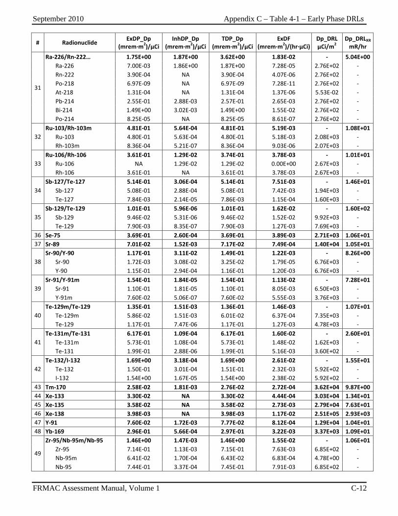
September 2010 Appendix C – Table 4-1 – Early Phase DRLs
FRMAC Assessment Manual, Volume 1 C-12
# Radionuclide ExDP_Dp (mrem∙m2)/µCi
InhDP_Dp (mrem∙m2)/µCi
TDP_Dp (mrem∙m2)/µCi
ExDF (mrem∙m2)/(hr∙µCi)
Dp_DRL µCi/m2
Dp_DRLXR mR/hr
31
Ra-226/Rn-222… 1.75E+00 1.87E+00 3.62E+00 1.83E-02 - 5.04E+00 Ra-226 7.00E-03 1.86E+00 1.87E+00 7.28E-05 2.76E+02 - Rn-222 3.90E-04 NA 3.90E-04 4.07E-06 2.76E+02 - Po-218 6.97E-09 NA 6.97E-09 7.28E-11 2.76E+02 - At-218 1.31E-04 NA 1.31E-04 1.37E-06 5.53E-02 - Pb-214 2.55E-01 2.88E-03 2.57E-01 2.65E-03 2.76E+02 - Bi-214 1.49E+00 3.02E-03 1.49E+00 1.55E-02 2.76E+02 - Po-214 8.25E-05 NA 8.25E-05 8.61E-07 2.76E+02 -
32 Ru-103/Rh-103m 4.81E-01 5.64E-04 4.81E-01 5.19E-03 - 1.08E+01 Ru-103 4.80E-01 5.63E-04 4.80E-01 5.18E-03 2.08E+03 - Rh-103m 8.36E-04 5.21E-07 8.36E-04 9.03E-06 2.07E+03 -
33 Ru-106/Rh-106 3.61E-01 1.29E-02 3.74E-01 3.78E-03 - 1.01E+01 Ru-106 NA 1.29E-02 1.29E-02 0.00E+00 2.67E+03 - Rh-106 3.61E-01 NA 3.61E-01 3.78E-03 2.67E+03 -
34 Sb-127/Te-127 5.14E-01 3.06E-04 5.14E-01 7.51E-03 - 1.46E+01 Sb-127 5.08E-01 2.88E-04 5.08E-01 7.42E-03 1.94E+03 - Te-127 7.84E-03 2.14E-05 7.86E-03 1.15E-04 1.60E+03 -
35 Sb-129/Te-129 1.01E-01 5.96E-06 1.01E-01 1.62E-02 - 1.60E+02 Sb-129 9.46E-02 5.31E-06 9.46E-02 1.52E-02 9.92E+03 - Te-129 7.90E-03 8.35E-07 7.90E-03 1.27E-03 7.69E+03 -
36 Se-75 3.69E-01 2.60E-04 3.69E-01 3.89E-03 2.71E+03 1.06E+01 37 Sr-89 7.01E-02 1.52E-03 7.17E-02 7.49E-04 1.40E+04 1.05E+01
38 Sr-90/Y-90 1.17E-01 3.11E-02 1.49E-01 1.22E-03 - 8.26E+00 Sr-90 1.72E-03 3.08E-02 3.25E-02 1.79E-05 6.76E+03 - Y-90 1.15E-01 2.94E-04 1.16E-01 1.20E-03 6.76E+03 -
39 Sr-91/Y-91m 1.54E-01 1.84E-05 1.54E-01 1.13E-02 - 7.28E+01 Sr-91 1.10E-01 1.81E-05 1.10E-01 8.05E-03 6.50E+03 - Y-91m 7.60E-02 5.06E-07 7.60E-02 5.55E-03 3.76E+03 -
40 Te-129m/Te-129 1.35E-01 1.51E-03 1.36E-01 1.46E-03 - 1.07E+01 Te-129m 5.86E-02 1.51E-03 6.01E-02 6.37E-04 7.35E+03 - Te-129 1.17E-01 7.47E-06 1.17E-01 1.27E-03 4.78E+03 -
41 Te-131m/Te-131 6.17E-01 1.09E-04 6.17E-01 1.60E-02 - 2.60E+01 Te-131m 5.73E-01 1.08E-04 5.73E-01 1.48E-02 1.62E+03 - Te-131 1.99E-01 2.88E-06 1.99E-01 5.16E-03 3.60E+02 -
42 Te-132/I-132 1.69E+00 3.18E-04 1.69E+00 2.61E-02 - 1.55E+01 Te-132 1.50E-01 3.01E-04 1.51E-01 2.32E-03 5.92E+02 - I-132 1.54E+00 1.67E-05 1.54E+00 2.38E-02 5.92E+02 -
43 Tm-170 2.58E-02 1.81E-03 2.76E-02 2.72E-04 3.62E+04 9.87E+00 44 Xe-133 3.30E-02 NA 3.30E-02 4.44E-04 3.03E+04 1.34E+01 45 Xe-135 3.58E-02 NA 3.58E-02 2.73E-03 2.79E+04 7.63E+01 46 Xe-138 3.98E-03 NA 3.98E-03 1.17E-02 2.51E+05 2.93E+03 47 Y-91 7.60E-02 1.72E-03 7.77E-02 8.12E-04 1.29E+04 1.04E+01 48 Yb-169 2.96E-01 5.66E-04 2.97E-01 3.22E-03 3.37E+03 1.09E+01
49
Zr-95/Nb-95m/Nb-95 1.46E+00 1.47E-03 1.46E+00 1.55E-02 - 1.06E+01 Zr-95 7.14E-01 1.13E-03 7.15E-01 7.63E-03 6.85E+02 - Nb-95m 6.41E-02 1.70E-04 6.43E-02 6.83E-04 4.78E+00 - Nb-95 7.44E-01 3.37E-04 7.45E-01 7.91E-03 6.85E+02 -
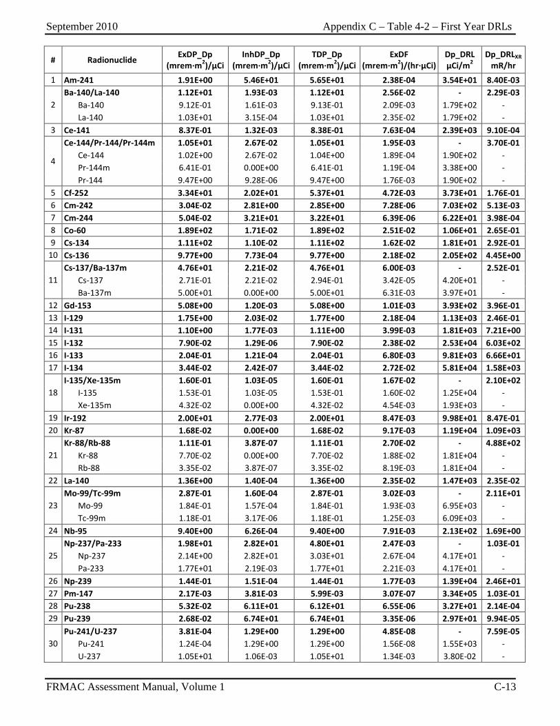
September 2010 Appendix C – Table 4-2 – First Year DRLs
FRMAC Assessment Manual, Volume 1 C-13
# Radionuclide ExDP_Dp (mrem∙m2)/µCi
InhDP_Dp (mrem∙m2)/µCi
TDP_Dp (mrem∙m2)/µCi
ExDF (mrem∙m2)/(hr∙µCi)
Dp_DRL µCi/m2
Dp_DRLXR mR/hr
1 Am-241 1.91E+00 5.46E+01 5.65E+01 2.38E-04 3.54E+01 8.40E-03
2 Ba-140/La-140 1.12E+01 1.93E-03 1.12E+01 2.56E-02 - 2.29E-03 Ba-140 9.12E-01 1.61E-03 9.13E-01 2.09E-03 1.79E+02 - La-140 1.03E+01 3.15E-04 1.03E+01 2.35E-02 1.79E+02 -
3 Ce-141 8.37E-01 1.32E-03 8.38E-01 7.63E-04 2.39E+03 9.10E-04
4
Ce-144/Pr-144/Pr-144m 1.05E+01 2.67E-02 1.05E+01 1.95E-03 - 3.70E-01 Ce-144 1.02E+00 2.67E-02 1.04E+00 1.89E-04 1.90E+02 - Pr-144m 6.41E-01 0.00E+00 6.41E-01 1.19E-04 3.38E+00 - Pr-144 9.47E+00 9.28E-06 9.47E+00 1.76E-03 1.90E+02 -
5 Cf-252 3.34E+01 2.02E+01 5.37E+01 4.72E-03 3.73E+01 1.76E-01 6 Cm-242 3.04E-02 2.81E+00 2.85E+00 7.28E-06 7.03E+02 5.13E-03 7 Cm-244 5.04E-02 3.21E+01 3.22E+01 6.39E-06 6.22E+01 3.98E-04 8 Co-60 1.89E+02 1.71E-02 1.89E+02 2.51E-02 1.06E+01 2.65E-01 9 Cs-134 1.11E+02 1.10E-02 1.11E+02 1.62E-02 1.81E+01 2.92E-01
10 Cs-136 9.77E+00 7.73E-04 9.77E+00 2.18E-02 2.05E+02 4.45E+00
11 Cs-137/Ba-137m 4.76E+01 2.21E-02 4.76E+01 6.00E-03 - 2.52E-01 Cs-137 2.71E-01 2.21E-02 2.94E-01 3.42E-05 4.20E+01 - Ba-137m 5.00E+01 0.00E+00 5.00E+01 6.31E-03 3.97E+01 -
12 Gd-153 5.08E+00 1.20E-03 5.08E+00 1.01E-03 3.93E+02 3.96E-01 13 I-129 1.75E+00 2.03E-02 1.77E+00 2.18E-04 1.13E+03 2.46E-01 14 I-131 1.10E+00 1.77E-03 1.11E+00 3.99E-03 1.81E+03 7.21E+00 15 I-132 7.90E-02 1.29E-06 7.90E-02 2.38E-02 2.53E+04 6.03E+02 16 I-133 2.04E-01 1.21E-04 2.04E-01 6.80E-03 9.81E+03 6.66E+01 17 I-134 3.44E-02 2.42E-07 3.44E-02 2.72E-02 5.81E+04 1.58E+03
18 I-135/Xe-135m 1.60E-01 1.03E-05 1.60E-01 1.67E-02 - 2.10E+02 I-135 1.53E-01 1.03E-05 1.53E-01 1.60E-02 1.25E+04 - Xe-135m 4.32E-02 0.00E+00 4.32E-02 4.54E-03 1.93E+03 -
19 Ir-192 2.00E+01 2.77E-03 2.00E+01 8.47E-03 9.98E+01 8.47E-01 20 Kr-87 1.68E-02 0.00E+00 1.68E-02 9.17E-03 1.19E+04 1.09E+03
21 Kr-88/Rb-88 1.11E-01 3.87E-07 1.11E-01 2.70E-02 - 4.88E+02 Kr-88 7.70E-02 0.00E+00 7.70E-02 1.88E-02 1.81E+04 - Rb-88 3.35E-02 3.87E-07 3.35E-02 8.19E-03 1.81E+04 -
22 La-140 1.36E+00 1.40E-04 1.36E+00 2.35E-02 1.47E+03 2.35E-02
23 Mo-99/Tc-99m 2.87E-01 1.60E-04 2.87E-01 3.02E-03 - 2.11E+01 Mo-99 1.84E-01 1.57E-04 1.84E-01 1.93E-03 6.95E+03 - Tc-99m 1.18E-01 3.17E-06 1.18E-01 1.25E-03 6.09E+03 -
24 Nb-95 9.40E+00 6.26E-04 9.40E+00 7.91E-03 2.13E+02 1.69E+00
25 Np-237/Pa-233 1.98E+01 2.82E+01 4.80E+01 2.47E-03 - 1.03E-01 Np-237 2.14E+00 2.82E+01 3.03E+01 2.67E-04 4.17E+01 - Pa-233 1.77E+01 2.19E-03 1.77E+01 2.21E-03 4.17E+01 -
26 Np-239 1.44E-01 1.51E-04 1.44E-01 1.77E-03 1.39E+04 2.46E+01 27 Pm-147 2.17E-03 3.81E-03 5.99E-03 3.07E-07 3.34E+05 1.03E-01 28 Pu-238 5.32E-02 6.11E+01 6.12E+01 6.55E-06 3.27E+01 2.14E-04 29 Pu-239 2.68E-02 6.74E+01 6.74E+01 3.35E-06 2.97E+01 9.94E-05
30 Pu-241/U-237 3.81E-04 1.29E+00 1.29E+00 4.85E-08 - 7.59E-05 Pu-241 1.24E-04 1.29E+00 1.29E+00 1.56E-08 1.55E+03 - U-237 1.05E+01 1.06E-03 1.05E+01 1.34E-03 3.80E-02 -
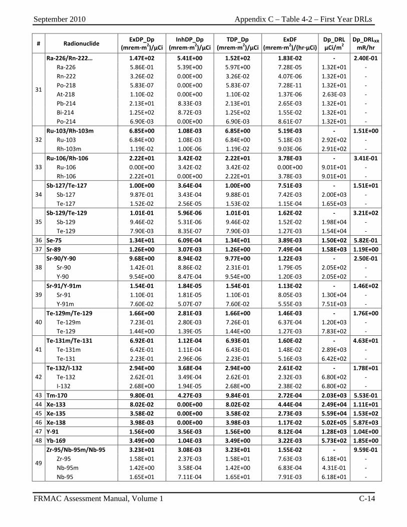
September 2010 Appendix C – Table 4-2 – First Year DRLs
FRMAC Assessment Manual, Volume 1 C-14
# Radionuclide ExDP_Dp (mrem∙m2)/µCi
InhDP_Dp (mrem∙m2)/µCi
TDP_Dp (mrem∙m2)/µCi
ExDF (mrem∙m2)/(hr∙µCi)
Dp_DRL µCi/m2
Dp_DRLXR mR/hr
31
Ra-226/Rn-222… 1.47E+02 5.41E+00 1.52E+02 1.83E-02 - 2.40E-01 Ra-226 5.86E-01 5.39E+00 5.97E+00 7.28E-05 1.32E+01 - Rn-222 3.26E-02 0.00E+00 3.26E-02 4.07E-06 1.32E+01 - Po-218 5.83E-07 0.00E+00 5.83E-07 7.28E-11 1.32E+01 - At-218 1.10E-02 0.00E+00 1.10E-02 1.37E-06 2.63E-03 - Pb-214 2.13E+01 8.33E-03 2.13E+01 2.65E-03 1.32E+01 - Bi-214 1.25E+02 8.72E-03 1.25E+02 1.55E-02 1.32E+01 - Po-214 6.90E-03 0.00E+00 6.90E-03 8.61E-07 1.32E+01 -
32 Ru-103/Rh-103m 6.85E+00 1.08E-03 6.85E+00 5.19E-03 - 1.51E+00 Ru-103 6.84E+00 1.08E-03 6.84E+00 5.18E-03 2.92E+02 - Rh-103m 1.19E-02 1.00E-06 1.19E-02 9.03E-06 2.91E+02 -
33 Ru-106/Rh-106 2.22E+01 3.42E-02 2.22E+01 3.78E-03 - 3.41E-01 Ru-106 0.00E+00 3.42E-02 3.42E-02 0.00E+00 9.01E+01 - Rh-106 2.22E+01 0.00E+00 2.22E+01 3.78E-03 9.01E+01 -
34 Sb-127/Te-127 1.00E+00 3.64E-04 1.00E+00 7.51E-03 - 1.51E+01 Sb-127 9.87E-01 3.43E-04 9.88E-01 7.42E-03 2.00E+03 - Te-127 1.52E-02 2.56E-05 1.53E-02 1.15E-04 1.65E+03 -
35 Sb-129/Te-129 1.01E-01 5.96E-06 1.01E-01 1.62E-02 - 3.21E+02 Sb-129 9.46E-02 5.31E-06 9.46E-02 1.52E-02 1.98E+04 - Te-129 7.90E-03 8.35E-07 7.90E-03 1.27E-03 1.54E+04 -
36 Se-75 1.34E+01 6.09E-04 1.34E+01 3.89E-03 1.50E+02 5.82E-01 37 Sr-89 1.26E+00 3.07E-03 1.26E+00 7.49E-04 1.58E+03 1.19E+00
38 Sr-90/Y-90 9.68E+00 8.94E-02 9.77E+00 1.22E-03 - 2.50E-01 Sr-90 1.42E-01 8.86E-02 2.31E-01 1.79E-05 2.05E+02 - Y-90 9.54E+00 8.47E-04 9.54E+00 1.20E-03 2.05E+02 -
39 Sr-91/Y-91m 1.54E-01 1.84E-05 1.54E-01 1.13E-02 - 1.46E+02 Sr-91 1.10E-01 1.81E-05 1.10E-01 8.05E-03 1.30E+04 - Y-91m 7.60E-02 5.07E-07 7.60E-02 5.55E-03 7.51E+03 -
40 Te-129m/Te-129 1.66E+00 2.81E-03 1.66E+00 1.46E-03 - 1.76E+00 Te-129m 7.23E-01 2.80E-03 7.26E-01 6.37E-04 1.20E+03 - Te-129 1.44E+00 1.39E-05 1.44E+00 1.27E-03 7.83E+02 -
41 Te-131m/Te-131 6.92E-01 1.12E-04 6.93E-01 1.60E-02 - 4.63E+01 Te-131m 6.42E-01 1.11E-04 6.43E-01 1.48E-02 2.89E+03 - Te-131 2.23E-01 2.96E-06 2.23E-01 5.16E-03 6.42E+02 -
42 Te-132/I-132 2.94E+00 3.68E-04 2.94E+00 2.61E-02 - 1.78E+01 Te-132 2.62E-01 3.49E-04 2.62E-01 2.32E-03 6.80E+02 - I-132 2.68E+00 1.94E-05 2.68E+00 2.38E-02 6.80E+02 -
43 Tm-170 9.80E-01 4.27E-03 9.84E-01 2.72E-04 2.03E+03 5.53E-01 44 Xe-133 8.02E-02 0.00E+00 8.02E-02 4.44E-04 2.49E+04 1.11E+01 45 Xe-135 3.58E-02 0.00E+00 3.58E-02 2.73E-03 5.59E+04 1.53E+02 46 Xe-138 3.98E-03 0.00E+00 3.98E-03 1.17E-02 5.02E+05 5.87E+03 47 Y-91 1.56E+00 3.56E-03 1.56E+00 8.12E-04 1.28E+03 1.04E+00 48 Yb-169 3.49E+00 1.04E-03 3.49E+00 3.22E-03 5.73E+02 1.85E+00
49
Zr-95/Nb-95m/Nb-95 3.23E+01 3.08E-03 3.23E+01 1.55E-02 - 9.59E-01 Zr-95 1.58E+01 2.37E-03 1.58E+01 7.63E-03 6.18E+01 - Nb-95m 1.42E+00 3.58E-04 1.42E+00 6.83E-04 4.31E-01 - Nb-95 1.65E+01 7.11E-04 1.65E+01 7.91E-03 6.18E+01 -
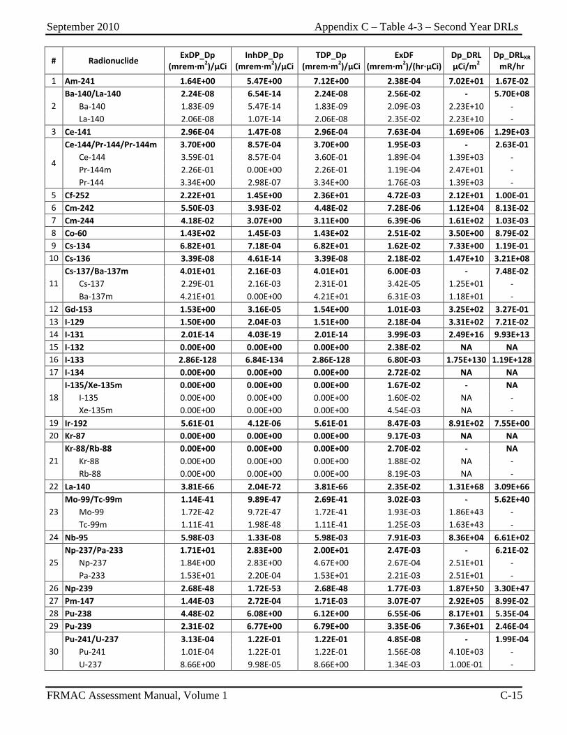
September 2010 Appendix C – Table 4-3 – Second Year DRLs
FRMAC Assessment Manual, Volume 1 C-15
# Radionuclide ExDP_Dp (mrem∙m2)/µCi
InhDP_Dp (mrem∙m2)/µCi
TDP_Dp (mrem∙m2)/µCi
ExDF (mrem∙m2)/(hr∙µCi)
Dp_DRL µCi/m2
Dp_DRLXR mR/hr
1 Am-241 1.64E+00 5.47E+00 7.12E+00 2.38E-04 7.02E+01 1.67E-02
2 Ba-140/La-140 2.24E-08 6.54E-14 2.24E-08 2.56E-02 - 5.70E+08 Ba-140 1.83E-09 5.47E-14 1.83E-09 2.09E-03 2.23E+10 - La-140 2.06E-08 1.07E-14 2.06E-08 2.35E-02 2.23E+10 -
3 Ce-141 2.96E-04 1.47E-08 2.96E-04 7.63E-04 1.69E+06 1.29E+03
4
Ce-144/Pr-144/Pr-144m 3.70E+00 8.57E-04 3.70E+00 1.95E-03 - 2.63E-01 Ce-144 3.59E-01 8.57E-04 3.60E-01 1.89E-04 1.39E+03 - Pr-144m 2.26E-01 0.00E+00 2.26E-01 1.19E-04 2.47E+01 - Pr-144 3.34E+00 2.98E-07 3.34E+00 1.76E-03 1.39E+03 -
5 Cf-252 2.22E+01 1.45E+00 2.36E+01 4.72E-03 2.12E+01 1.00E-01 6 Cm-242 5.50E-03 3.93E-02 4.48E-02 7.28E-06 1.12E+04 8.13E-02 7 Cm-244 4.18E-02 3.07E+00 3.11E+00 6.39E-06 1.61E+02 1.03E-03 8 Co-60 1.43E+02 1.45E-03 1.43E+02 2.51E-02 3.50E+00 8.79E-02 9 Cs-134 6.82E+01 7.18E-04 6.82E+01 1.62E-02 7.33E+00 1.19E-01
10 Cs-136 3.39E-08 4.61E-14 3.39E-08 2.18E-02 1.47E+10 3.21E+08
11 Cs-137/Ba-137m 4.01E+01 2.16E-03 4.01E+01 6.00E-03 - 7.48E-02 Cs-137 2.29E-01 2.16E-03 2.31E-01 3.42E-05 1.25E+01 - Ba-137m 4.21E+01 0.00E+00 4.21E+01 6.31E-03 1.18E+01 -
12 Gd-153 1.53E+00 3.16E-05 1.54E+00 1.01E-03 3.25E+02 3.27E-01 13 I-129 1.50E+00 2.04E-03 1.51E+00 2.18E-04 3.31E+02 7.21E-02 14 I-131 2.01E-14 4.03E-19 2.01E-14 3.99E-03 2.49E+16 9.93E+13 15 I-132 0.00E+00 0.00E+00 0.00E+00 2.38E-02 NA NA 16 I-133 2.86E-128 6.84E-134 2.86E-128 6.80E-03 1.75E+130 1.19E+128 17 I-134 0.00E+00 0.00E+00 0.00E+00 2.72E-02 NA NA
18 I-135/Xe-135m 0.00E+00 0.00E+00 0.00E+00 1.67E-02 - NA I-135 0.00E+00 0.00E+00 0.00E+00 1.60E-02 NA - Xe-135m 0.00E+00 0.00E+00 0.00E+00 4.54E-03 NA -
19 Ir-192 5.61E-01 4.12E-06 5.61E-01 8.47E-03 8.91E+02 7.55E+00 20 Kr-87 0.00E+00 0.00E+00 0.00E+00 9.17E-03 NA NA
21 Kr-88/Rb-88 0.00E+00 0.00E+00 0.00E+00 2.70E-02 - NA Kr-88 0.00E+00 0.00E+00 0.00E+00 1.88E-02 NA - Rb-88 0.00E+00 0.00E+00 0.00E+00 8.19E-03 NA -
22 La-140 3.81E-66 2.04E-72 3.81E-66 2.35E-02 1.31E+68 3.09E+66
23 Mo-99/Tc-99m 1.14E-41 9.89E-47 2.69E-41 3.02E-03 - 5.62E+40 Mo-99 1.72E-42 9.72E-47 1.72E-41 1.93E-03 1.86E+43 - Tc-99m 1.11E-41 1.98E-48 1.11E-41 1.25E-03 1.63E+43 -
24 Nb-95 5.98E-03 1.33E-08 5.98E-03 7.91E-03 8.36E+04 6.61E+02
25 Np-237/Pa-233 1.71E+01 2.83E+00 2.00E+01 2.47E-03 - 6.21E-02 Np-237 1.84E+00 2.83E+00 4.67E+00 2.67E-04 2.51E+01 - Pa-233 1.53E+01 2.20E-04 1.53E+01 2.21E-03 2.51E+01 -
26 Np-239 2.68E-48 1.72E-53 2.68E-48 1.77E-03 1.87E+50 3.30E+47 27 Pm-147 1.44E-03 2.72E-04 1.71E-03 3.07E-07 2.92E+05 8.99E-02 28 Pu-238 4.48E-02 6.08E+00 6.12E+00 6.55E-06 8.17E+01 5.35E-04 29 Pu-239 2.31E-02 6.77E+00 6.79E+00 3.35E-06 7.36E+01 2.46E-04
30 Pu-241/U-237 3.13E-04 1.22E-01 1.22E-01 4.85E-08 - 1.99E-04 Pu-241 1.01E-04 1.22E-01 1.22E-01 1.56E-08 4.10E+03 - U-237 8.66E+00 9.98E-05 8.66E+00 1.34E-03 1.00E-01 -
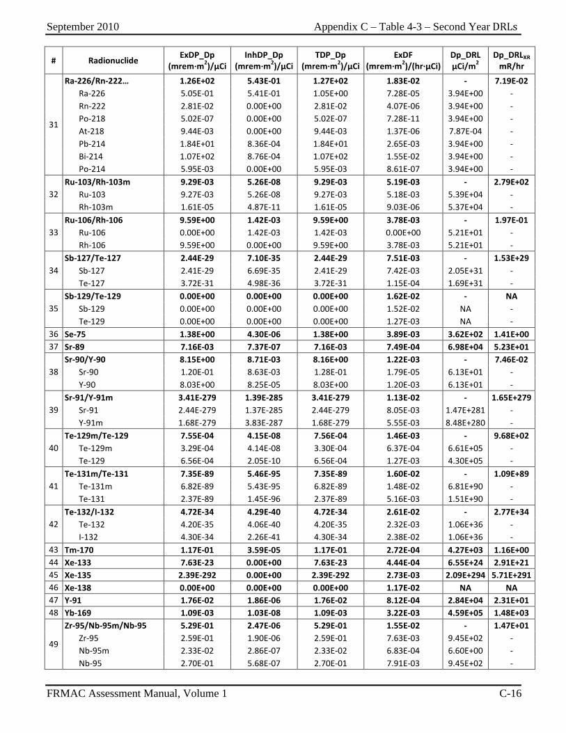
September 2010 Appendix C – Table 4-3 – Second Year DRLs
FRMAC Assessment Manual, Volume 1 C-16
# Radionuclide ExDP_Dp (mrem∙m2)/µCi
InhDP_Dp (mrem∙m2)/µCi
TDP_Dp (mrem∙m2)/µCi
ExDF (mrem∙m2)/(hr∙µCi)
Dp_DRL µCi/m2
Dp_DRLXR mR/hr
31
Ra-226/Rn-222… 1.26E+02 5.43E-01 1.27E+02 1.83E-02 - 7.19E-02 Ra-226 5.05E-01 5.41E-01 1.05E+00 7.28E-05 3.94E+00 - Rn-222 2.81E-02 0.00E+00 2.81E-02 4.07E-06 3.94E+00 - Po-218 5.02E-07 0.00E+00 5.02E-07 7.28E-11 3.94E+00 - At-218 9.44E-03 0.00E+00 9.44E-03 1.37E-06 7.87E-04 - Pb-214 1.84E+01 8.36E-04 1.84E+01 2.65E-03 3.94E+00 - Bi-214 1.07E+02 8.76E-04 1.07E+02 1.55E-02 3.94E+00 - Po-214 5.95E-03 0.00E+00 5.95E-03 8.61E-07 3.94E+00 -
32 Ru-103/Rh-103m 9.29E-03 5.26E-08 9.29E-03 5.19E-03 - 2.79E+02 Ru-103 9.27E-03 5.26E-08 9.27E-03 5.18E-03 5.39E+04 - Rh-103m 1.61E-05 4.87E-11 1.61E-05 9.03E-06 5.37E+04 -
33 Ru-106/Rh-106 9.59E+00 1.42E-03 9.59E+00 3.78E-03 - 1.97E-01 Ru-106 0.00E+00 1.42E-03 1.42E-03 0.00E+00 5.21E+01 - Rh-106 9.59E+00 0.00E+00 9.59E+00 3.78E-03 5.21E+01 -
34 Sb-127/Te-127 2.44E-29 7.10E-35 2.44E-29 7.51E-03 - 1.53E+29 Sb-127 2.41E-29 6.69E-35 2.41E-29 7.42E-03 2.05E+31 - Te-127 3.72E-31 4.98E-36 3.72E-31 1.15E-04 1.69E+31 -
35 Sb-129/Te-129 0.00E+00 0.00E+00 0.00E+00 1.62E-02 - NA Sb-129 0.00E+00 0.00E+00 0.00E+00 1.52E-02 NA - Te-129 0.00E+00 0.00E+00 0.00E+00 1.27E-03 NA -
36 Se-75 1.38E+00 4.30E-06 1.38E+00 3.89E-03 3.62E+02 1.41E+00 37 Sr-89 7.16E-03 7.37E-07 7.16E-03 7.49E-04 6.98E+04 5.23E+01
38 Sr-90/Y-90 8.15E+00 8.71E-03 8.16E+00 1.22E-03 - 7.46E-02 Sr-90 1.20E-01 8.63E-03 1.28E-01 1.79E-05 6.13E+01 - Y-90 8.03E+00 8.25E-05 8.03E+00 1.20E-03 6.13E+01 -
39 Sr-91/Y-91m 3.41E-279 1.39E-285 3.41E-279 1.13E-02 - 1.65E+279 Sr-91 2.44E-279 1.37E-285 2.44E-279 8.05E-03 1.47E+281 - Y-91m 1.68E-279 3.83E-287 1.68E-279 5.55E-03 8.48E+280 -
40 Te-129m/Te-129 7.55E-04 4.15E-08 7.56E-04 1.46E-03 - 9.68E+02 Te-129m 3.29E-04 4.14E-08 3.30E-04 6.37E-04 6.61E+05 - Te-129 6.56E-04 2.05E-10 6.56E-04 1.27E-03 4.30E+05 -
41 Te-131m/Te-131 7.35E-89 5.46E-95 7.35E-89 1.60E-02 - 1.09E+89 Te-131m 6.82E-89 5.43E-95 6.82E-89 1.48E-02 6.81E+90 - Te-131 2.37E-89 1.45E-96 2.37E-89 5.16E-03 1.51E+90 -
42 Te-132/I-132 4.72E-34 4.29E-40 4.72E-34 2.61E-02 - 2.77E+34 Te-132 4.20E-35 4.06E-40 4.20E-35 2.32E-03 1.06E+36 - I-132 4.30E-34 2.26E-41 4.30E-34 2.38E-02 1.06E+36 -
43 Tm-170 1.17E-01 3.59E-05 1.17E-01 2.72E-04 4.27E+03 1.16E+00 44 Xe-133 7.63E-23 0.00E+00 7.63E-23 4.44E-04 6.55E+24 2.91E+21 45 Xe-135 2.39E-292 0.00E+00 2.39E-292 2.73E-03 2.09E+294 5.71E+291 46 Xe-138 0.00E+00 0.00E+00 0.00E+00 1.17E-02 NA NA 47 Y-91 1.76E-02 1.86E-06 1.76E-02 8.12E-04 2.84E+04 2.31E+01 48 Yb-169 1.09E-03 1.03E-08 1.09E-03 3.22E-03 4.59E+05 1.48E+03
49
Zr-95/Nb-95m/Nb-95 5.29E-01 2.47E-06 5.29E-01 1.55E-02 - 1.47E+01 Zr-95 2.59E-01 1.90E-06 2.59E-01 7.63E-03 9.45E+02 - Nb-95m 2.33E-02 2.86E-07 2.33E-02 6.83E-04 6.60E+00 - Nb-95 2.70E-01 5.68E-07 2.70E-01 7.91E-03 9.45E+02 -
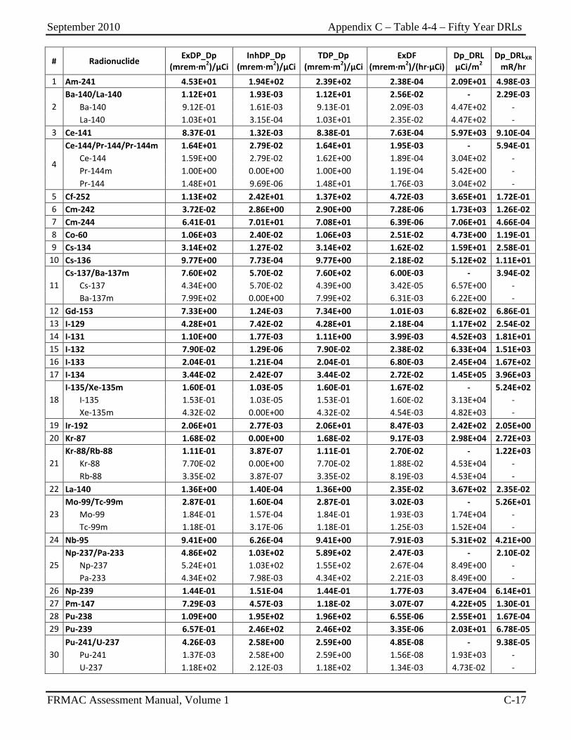
September 2010 Appendix C – Table 4-4 – Fifty Year DRLs
FRMAC Assessment Manual, Volume 1 C-17
# Radionuclide ExDP_Dp (mrem∙m2)/µCi
InhDP_Dp (mrem∙m2)/µCi
TDP_Dp (mrem∙m2)/µCi
ExDF (mrem∙m2)/(hr∙µCi)
Dp_DRL µCi/m2
Dp_DRLXR mR/hr
1 Am-241 4.53E+01 1.94E+02 2.39E+02 2.38E-04 2.09E+01 4.98E-03
2 Ba-140/La-140 1.12E+01 1.93E-03 1.12E+01 2.56E-02 - 2.29E-03 Ba-140 9.12E-01 1.61E-03 9.13E-01 2.09E-03 4.47E+02 - La-140 1.03E+01 3.15E-04 1.03E+01 2.35E-02 4.47E+02 -
3 Ce-141 8.37E-01 1.32E-03 8.38E-01 7.63E-04 5.97E+03 9.10E-04
4
Ce-144/Pr-144/Pr-144m 1.64E+01 2.79E-02 1.64E+01 1.95E-03 - 5.94E-01 Ce-144 1.59E+00 2.79E-02 1.62E+00 1.89E-04 3.04E+02 - Pr-144m 1.00E+00 0.00E+00 1.00E+00 1.19E-04 5.42E+00 - Pr-144 1.48E+01 9.69E-06 1.48E+01 1.76E-03 3.04E+02 -
5 Cf-252 1.13E+02 2.42E+01 1.37E+02 4.72E-03 3.65E+01 1.72E-01 6 Cm-242 3.72E-02 2.86E+00 2.90E+00 7.28E-06 1.73E+03 1.26E-02 7 Cm-244 6.41E-01 7.01E+01 7.08E+01 6.39E-06 7.06E+01 4.66E-04 8 Co-60 1.06E+03 2.40E-02 1.06E+03 2.51E-02 4.73E+00 1.19E-01 9 Cs-134 3.14E+02 1.27E-02 3.14E+02 1.62E-02 1.59E+01 2.58E-01
10 Cs-136 9.77E+00 7.73E-04 9.77E+00 2.18E-02 5.12E+02 1.11E+01
11 Cs-137/Ba-137m 7.60E+02 5.70E-02 7.60E+02 6.00E-03 - 3.94E-02 Cs-137 4.34E+00 5.70E-02 4.39E+00 3.42E-05 6.57E+00 - Ba-137m 7.99E+02 0.00E+00 7.99E+02 6.31E-03 6.22E+00 -
12 Gd-153 7.33E+00 1.24E-03 7.34E+00 1.01E-03 6.82E+02 6.86E-01 13 I-129 4.28E+01 7.42E-02 4.28E+01 2.18E-04 1.17E+02 2.54E-02 14 I-131 1.10E+00 1.77E-03 1.11E+00 3.99E-03 4.52E+03 1.81E+01 15 I-132 7.90E-02 1.29E-06 7.90E-02 2.38E-02 6.33E+04 1.51E+03 16 I-133 2.04E-01 1.21E-04 2.04E-01 6.80E-03 2.45E+04 1.67E+02 17 I-134 3.44E-02 2.42E-07 3.44E-02 2.72E-02 1.45E+05 3.96E+03
18 I-135/Xe-135m 1.60E-01 1.03E-05 1.60E-01 1.67E-02 - 5.24E+02 I-135 1.53E-01 1.03E-05 1.53E-01 1.60E-02 3.13E+04 - Xe-135m 4.32E-02 0.00E+00 4.32E-02 4.54E-03 4.82E+03 -
19 Ir-192 2.06E+01 2.77E-03 2.06E+01 8.47E-03 2.42E+02 2.05E+00 20 Kr-87 1.68E-02 0.00E+00 1.68E-02 9.17E-03 2.98E+04 2.72E+03
21 Kr-88/Rb-88 1.11E-01 3.87E-07 1.11E-01 2.70E-02 - 1.22E+03 Kr-88 7.70E-02 0.00E+00 7.70E-02 1.88E-02 4.53E+04 - Rb-88 3.35E-02 3.87E-07 3.35E-02 8.19E-03 4.53E+04 -
22 La-140 1.36E+00 1.40E-04 1.36E+00 2.35E-02 3.67E+02 2.35E-02
23 Mo-99/Tc-99m 2.87E-01 1.60E-04 2.87E-01 3.02E-03 - 5.26E+01 Mo-99 1.84E-01 1.57E-04 1.84E-01 1.93E-03 1.74E+04 - Tc-99m 1.18E-01 3.17E-06 1.18E-01 1.25E-03 1.52E+04 -
24 Nb-95 9.41E+00 6.26E-04 9.41E+00 7.91E-03 5.31E+02 4.21E+00
25 Np-237/Pa-233 4.86E+02 1.03E+02 5.89E+02 2.47E-03 - 2.10E-02 Np-237 5.24E+01 1.03E+02 1.55E+02 2.67E-04 8.49E+00 - Pa-233 4.34E+02 7.98E-03 4.34E+02 2.21E-03 8.49E+00 -
26 Np-239 1.44E-01 1.51E-04 1.44E-01 1.77E-03 3.47E+04 6.14E+01 27 Pm-147 7.29E-03 4.57E-03 1.18E-02 3.07E-07 4.22E+05 1.30E-01 28 Pu-238 1.09E+00 1.95E+02 1.96E+02 6.55E-06 2.55E+01 1.67E-04 29 Pu-239 6.57E-01 2.46E+02 2.46E+02 3.35E-06 2.03E+01 6.78E-05
30 Pu-241/U-237 4.26E-03 2.58E+00 2.59E+00 4.85E-08 - 9.38E-05 Pu-241 1.37E-03 2.58E+00 2.59E+00 1.56E-08 1.93E+03 - U-237 1.18E+02 2.12E-03 1.18E+02 1.34E-03 4.73E-02 -
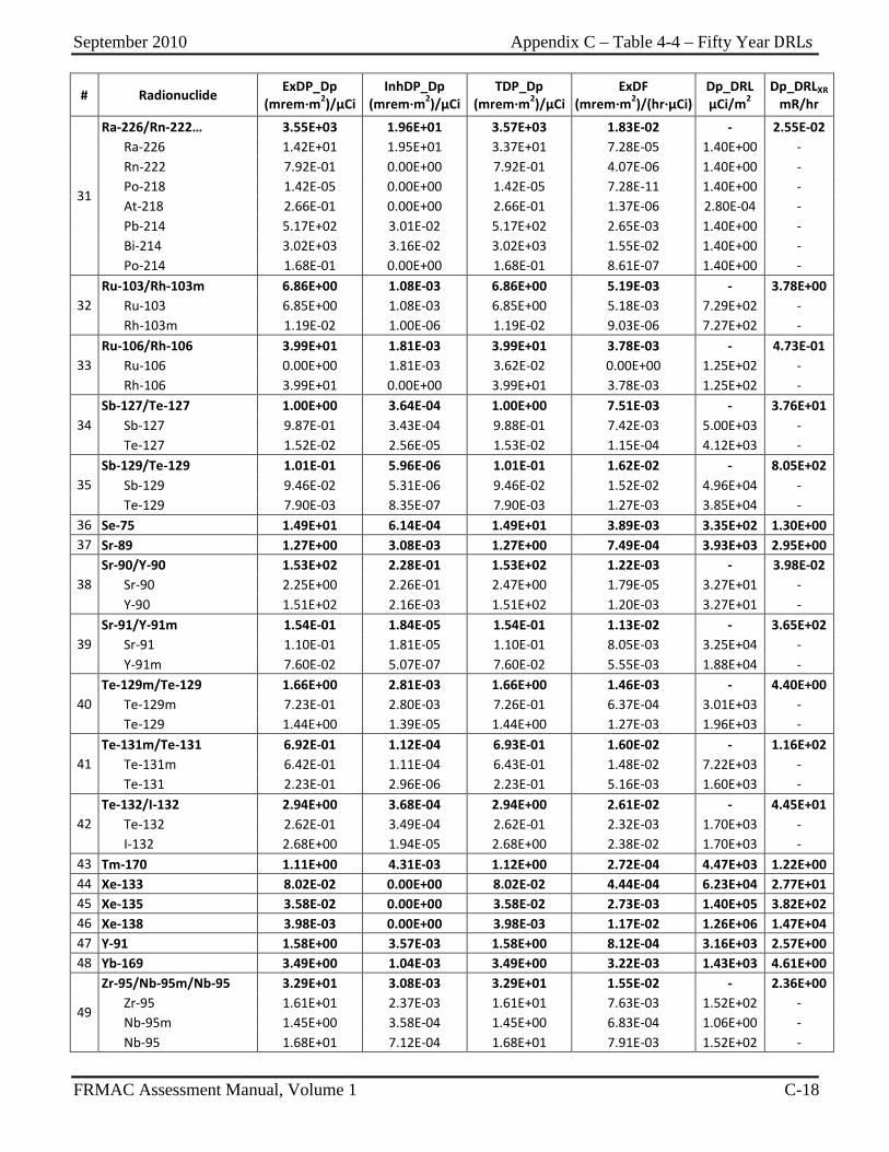
September 2010 Appendix C – Table 4-4 – Fifty Year DRLs
FRMAC Assessment Manual, Volume 1 C-18
# Radionuclide ExDP_Dp (mrem∙m2)/µCi
InhDP_Dp (mrem∙m2)/µCi
TDP_Dp (mrem∙m2)/µCi
ExDF (mrem∙m2)/(hr∙µCi)
Dp_DRL µCi/m2
Dp_DRLXR mR/hr
31
Ra-226/Rn-222… 3.55E+03 1.96E+01 3.57E+03 1.83E-02 - 2.55E-02 Ra-226 1.42E+01 1.95E+01 3.37E+01 7.28E-05 1.40E+00 - Rn-222 7.92E-01 0.00E+00 7.92E-01 4.07E-06 1.40E+00 - Po-218 1.42E-05 0.00E+00 1.42E-05 7.28E-11 1.40E+00 - At-218 2.66E-01 0.00E+00 2.66E-01 1.37E-06 2.80E-04 - Pb-214 5.17E+02 3.01E-02 5.17E+02 2.65E-03 1.40E+00 - Bi-214 3.02E+03 3.16E-02 3.02E+03 1.55E-02 1.40E+00 - Po-214 1.68E-01 0.00E+00 1.68E-01 8.61E-07 1.40E+00 -
32 Ru-103/Rh-103m 6.86E+00 1.08E-03 6.86E+00 5.19E-03 - 3.78E+00 Ru-103 6.85E+00 1.08E-03 6.85E+00 5.18E-03 7.29E+02 - Rh-103m 1.19E-02 1.00E-06 1.19E-02 9.03E-06 7.27E+02 -
33 Ru-106/Rh-106 3.99E+01 1.81E-03 3.99E+01 3.78E-03 - 4.73E-01 Ru-106 0.00E+00 1.81E-03 3.62E-02 0.00E+00 1.25E+02 - Rh-106 3.99E+01 0.00E+00 3.99E+01 3.78E-03 1.25E+02 -
34 Sb-127/Te-127 1.00E+00 3.64E-04 1.00E+00 7.51E-03 - 3.76E+01 Sb-127 9.87E-01 3.43E-04 9.88E-01 7.42E-03 5.00E+03 - Te-127 1.52E-02 2.56E-05 1.53E-02 1.15E-04 4.12E+03 -
35 Sb-129/Te-129 1.01E-01 5.96E-06 1.01E-01 1.62E-02 - 8.05E+02 Sb-129 9.46E-02 5.31E-06 9.46E-02 1.52E-02 4.96E+04 - Te-129 7.90E-03 8.35E-07 7.90E-03 1.27E-03 3.85E+04 -
36 Se-75 1.49E+01 6.14E-04 1.49E+01 3.89E-03 3.35E+02 1.30E+00 37 Sr-89 1.27E+00 3.08E-03 1.27E+00 7.49E-04 3.93E+03 2.95E+00
38 Sr-90/Y-90 1.53E+02 2.28E-01 1.53E+02 1.22E-03 - 3.98E-02 Sr-90 2.25E+00 2.26E-01 2.47E+00 1.79E-05 3.27E+01 - Y-90 1.51E+02 2.16E-03 1.51E+02 1.20E-03 3.27E+01 -
39 Sr-91/Y-91m 1.54E-01 1.84E-05 1.54E-01 1.13E-02 - 3.65E+02 Sr-91 1.10E-01 1.81E-05 1.10E-01 8.05E-03 3.25E+04 - Y-91m 7.60E-02 5.07E-07 7.60E-02 5.55E-03 1.88E+04 -
40 Te-129m/Te-129 1.66E+00 2.81E-03 1.66E+00 1.46E-03 - 4.40E+00 Te-129m 7.23E-01 2.80E-03 7.26E-01 6.37E-04 3.01E+03 - Te-129 1.44E+00 1.39E-05 1.44E+00 1.27E-03 1.96E+03 -
41 Te-131m/Te-131 6.92E-01 1.12E-04 6.93E-01 1.60E-02 - 1.16E+02 Te-131m 6.42E-01 1.11E-04 6.43E-01 1.48E-02 7.22E+03 - Te-131 2.23E-01 2.96E-06 2.23E-01 5.16E-03 1.60E+03 -
42 Te-132/I-132 2.94E+00 3.68E-04 2.94E+00 2.61E-02 - 4.45E+01 Te-132 2.62E-01 3.49E-04 2.62E-01 2.32E-03 1.70E+03 - I-132 2.68E+00 1.94E-05 2.68E+00 2.38E-02 1.70E+03 -
43 Tm-170 1.11E+00 4.31E-03 1.12E+00 2.72E-04 4.47E+03 1.22E+00 44 Xe-133 8.02E-02 0.00E+00 8.02E-02 4.44E-04 6.23E+04 2.77E+01 45 Xe-135 3.58E-02 0.00E+00 3.58E-02 2.73E-03 1.40E+05 3.82E+02 46 Xe-138 3.98E-03 0.00E+00 3.98E-03 1.17E-02 1.26E+06 1.47E+04 47 Y-91 1.58E+00 3.57E-03 1.58E+00 8.12E-04 3.16E+03 2.57E+00 48 Yb-169 3.49E+00 1.04E-03 3.49E+00 3.22E-03 1.43E+03 4.61E+00
49
Zr-95/Nb-95m/Nb-95 3.29E+01 3.08E-03 3.29E+01 1.55E-02 - 2.36E+00 Zr-95 1.61E+01 2.37E-03 1.61E+01 7.63E-03 1.52E+02 - Nb-95m 1.45E+00 3.58E-04 1.45E+00 6.83E-04 1.06E+00 - Nb-95 1.68E+01 7.12E-04 1.68E+01 7.91E-03 1.52E+02 -
September 2010 Appendix C – Table 5 – Skin Dose Coefficients
FRMAC Assessment Manual, Volume 1 C-19
This Table is RESERVED for the future inclusion of Skin Dose Data.
September 2010 Appendix C – Table 5 – Skin Dose Coefficients
FRMAC Assessment Manual, Volume 1 C-20
This page intentionally left blank.

September 2010 Appendix C – Table 6 – Shielding Factors
FRMAC Assessment Manual, Volume 1 C-21
Table 6-1 Gamma Cloud Source Shielding Factors
Structure or Location Shielding Factor a Outside 1.0 Vehicles 1.0
Wood frame house b (no basement) 0.9 Basement of wood frame house 0.6 Masonry house (no basement) 0.6 Basement of masonry house 0.4
Large office or industrial building 0.2
Source: EGG75 a Ratio of the interior dose to the exterior dose. b A wood frame house with brick or stone veneer is approximately equivalent to
a masonry house for shielding purposes.
Table 6-2 Surface Deposition Shielding Factors
Structure or Location Representative Shielding Factor a
Cars on fully contaminated road 0.5 Cars on fully decontaminated 50-foot road 0.25 Trains 0.4 One- and two-story wood-frame house (no basement) 0.4 b One- and two-story block and brick house (no basement) 0.2 b House basement, one or two walls fully exposed 0.1 b One story, less than two feet of basement, wall exposed 0.05 b Two stories, less than two feet of basement, wall exposed 0.03 b Three- or four-story structures, 5,000 to 10,000 square feet per floor First and second floors 0.05 b Basement 0.01 b Multi-story structures, greater than 10,000 square feet per floor Upper floors 0.01 b Basement 0.005 b
Source: EGG75 a Ratio of the interior dose to the exterior dose. b Away from doors and windows.

September 2010 Appendix C – Table 6 – Shielding Factors
FRMAC Assessment Manual, Volume 1 C-22
This page intentionally left blank.
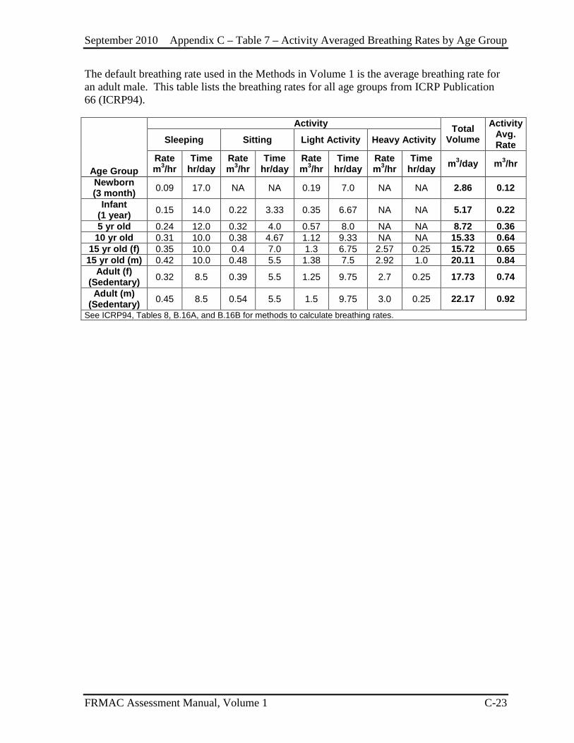
September 2010 Appendix C – Table 7 – Activity Averaged Breathing Rates by Age Group
FRMAC Assessment Manual, Volume 1 C-23
The default breathing rate used in the Methods in Volume 1 is the average breathing rate for an adult male. This table lists the breathing rates for all age groups from ICRP Publication 66 (ICRP94).
Age Group
Activity Total Volume
Activity Avg. Rate Sleeping Sitting Light Activity Heavy Activity
Rate m3/hr
Time hr/day
Rate m3/hr
Time hr/day
Rate m3/hr
Time hr/day
Rate m3/hr
Time hr/day m3/day m3/hr
Newborn (3 month) 0.09 17.0 NA NA 0.19 7.0 NA NA 2.86 0.12
Infant (1 year) 0.15 14.0 0.22 3.33 0.35 6.67 NA NA 5.17 0.22
5 yr old 0.24 12.0 0.32 4.0 0.57 8.0 NA NA 8.72 0.36 10 yr old 0.31 10.0 0.38 4.67 1.12 9.33 NA NA 15.33 0.64
15 yr old (f) 0.35 10.0 0.4 7.0 1.3 6.75 2.57 0.25 15.72 0.65 15 yr old (m) 0.42 10.0 0.48 5.5 1.38 7.5 2.92 1.0 20.11 0.84
Adult (f) (Sedentary) 0.32 8.5 0.39 5.5 1.25 9.75 2.7 0.25 17.73 0.74
Adult (m) (Sedentary) 0.45 8.5 0.54 5.5 1.5 9.75 3.0 0.25 22.17 0.92
See ICRP94, Tables 8, B.16A, and B.16B for methods to calculate breathing rates.
September 2010 Appendix C – Table 7 – Activity Averaged Breathing Rates by Age Group
FRMAC Assessment Manual, Volume 1 C-24
This page intentionally left blank.
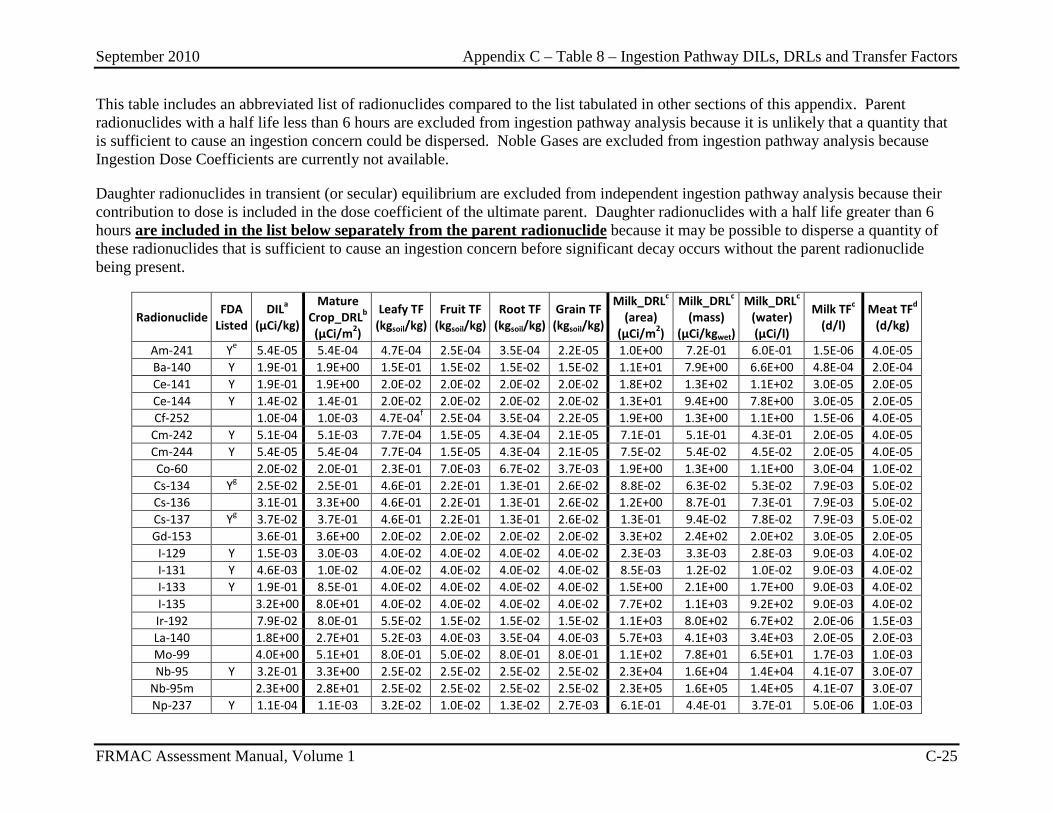
September 2010 Appendix C – Table 8 – Ingestion Pathway DILs, DRLs and Transfer Factors
FRMAC Assessment Manual, Volume 1 C-25
This table includes an abbreviated list of radionuclides compared to the list tabulated in other sections of this appendix. Parent radionuclides with a half life less than 6 hours are excluded from ingestion pathway analysis because it is unlikely that a quantity that is sufficient to cause an ingestion concern could be dispersed. Noble Gases are excluded from ingestion pathway analysis because Ingestion Dose Coefficients are currently not available.
Daughter radionuclides in transient (or secular) equilibrium are excluded from independent ingestion pathway analysis because their contribution to dose is included in the dose coefficient of the ultimate parent. Daughter radionuclides with a half life greater than 6 hours are included in the list below separately from the parent radionuclide because it may be possible to disperse a quantity of these radionuclides that is sufficient to cause an ingestion concern before significant decay occurs without the parent radionuclide being present.
Radionuclide FDA Listed
DILa (µCi/kg)
Mature Crop_DRLb (µCi/m2)
Leafy TF (kgsoil/kg)
Fruit TF (kgsoil/kg)
Root TF (kgsoil/kg)
Grain TF (kgsoil/kg)
Milk_DRLc (area)
(µCi/m2)
Milk_DRLc (mass)
(µCi/kgwet)
Milk_DRLc (water) (µCi/l)
Milk TFc (d/l)
Meat TFd (d/kg)
Am-241 Ye 5.4E-05 5.4E-04 4.7E-04 2.5E-04 3.5E-04 2.2E-05 1.0E+00 7.2E-01 6.0E-01 1.5E-06 4.0E-05 Ba-140 Y 1.9E-01 1.9E+00 1.5E-01 1.5E-02 1.5E-02 1.5E-02 1.1E+01 7.9E+00 6.6E+00 4.8E-04 2.0E-04 Ce-141 Y 1.9E-01 1.9E+00 2.0E-02 2.0E-02 2.0E-02 2.0E-02 1.8E+02 1.3E+02 1.1E+02 3.0E-05 2.0E-05 Ce-144 Y 1.4E-02 1.4E-01 2.0E-02 2.0E-02 2.0E-02 2.0E-02 1.3E+01 9.4E+00 7.8E+00 3.0E-05 2.0E-05 Cf-252 1.0E-04 1.0E-03 4.7E-04f 2.5E-04 3.5E-04 2.2E-05 1.9E+00 1.3E+00 1.1E+00 1.5E-06 4.0E-05
Cm-242 Y 5.1E-04 5.1E-03 7.7E-04 1.5E-05 4.3E-04 2.1E-05 7.1E-01 5.1E-01 4.3E-01 2.0E-05 4.0E-05 Cm-244 Y 5.4E-05 5.4E-04 7.7E-04 1.5E-05 4.3E-04 2.1E-05 7.5E-02 5.4E-02 4.5E-02 2.0E-05 4.0E-05 Co-60 2.0E-02 2.0E-01 2.3E-01 7.0E-03 6.7E-02 3.7E-03 1.9E+00 1.3E+00 1.1E+00 3.0E-04 1.0E-02 Cs-134 Yg 2.5E-02 2.5E-01 4.6E-01 2.2E-01 1.3E-01 2.6E-02 8.8E-02 6.3E-02 5.3E-02 7.9E-03 5.0E-02 Cs-136 3.1E-01 3.3E+00 4.6E-01 2.2E-01 1.3E-01 2.6E-02 1.2E+00 8.7E-01 7.3E-01 7.9E-03 5.0E-02 Cs-137 Yg 3.7E-02 3.7E-01 4.6E-01 2.2E-01 1.3E-01 2.6E-02 1.3E-01 9.4E-02 7.8E-02 7.9E-03 5.0E-02 Gd-153 3.6E-01 3.6E+00 2.0E-02 2.0E-02 2.0E-02 2.0E-02 3.3E+02 2.4E+02 2.0E+02 3.0E-05 2.0E-05
I-129 Y 1.5E-03 3.0E-03 4.0E-02 4.0E-02 4.0E-02 4.0E-02 2.3E-03 3.3E-03 2.8E-03 9.0E-03 4.0E-02 I-131 Y 4.6E-03 1.0E-02 4.0E-02 4.0E-02 4.0E-02 4.0E-02 8.5E-03 1.2E-02 1.0E-02 9.0E-03 4.0E-02 I-133 Y 1.9E-01 8.5E-01 4.0E-02 4.0E-02 4.0E-02 4.0E-02 1.5E+00 2.1E+00 1.7E+00 9.0E-03 4.0E-02 I-135 3.2E+00 8.0E+01 4.0E-02 4.0E-02 4.0E-02 4.0E-02 7.7E+02 1.1E+03 9.2E+02 9.0E-03 4.0E-02 Ir-192 7.9E-02 8.0E-01 5.5E-02 1.5E-02 1.5E-02 1.5E-02 1.1E+03 8.0E+02 6.7E+02 2.0E-06 1.5E-03 La-140 1.8E+00 2.7E+01 5.2E-03 4.0E-03 3.5E-04 4.0E-03 5.7E+03 4.1E+03 3.4E+03 2.0E-05 2.0E-03 Mo-99 4.0E+00 5.1E+01 8.0E-01 5.0E-02 8.0E-01 8.0E-01 1.1E+02 7.8E+01 6.5E+01 1.7E-03 1.0E-03 Nb-95 Y 3.2E-01 3.3E+00 2.5E-02 2.5E-02 2.5E-02 2.5E-02 2.3E+04 1.6E+04 1.4E+04 4.1E-07 3.0E-07
Nb-95m 2.3E+00 2.8E+01 2.5E-02 2.5E-02 2.5E-02 2.5E-02 2.3E+05 1.6E+05 1.4E+05 4.1E-07 3.0E-07 Np-237 Y 1.1E-04 1.1E-03 3.2E-02 1.0E-02 1.3E-02 2.7E-03 6.1E-01 4.4E-01 3.7E-01 5.0E-06 1.0E-03
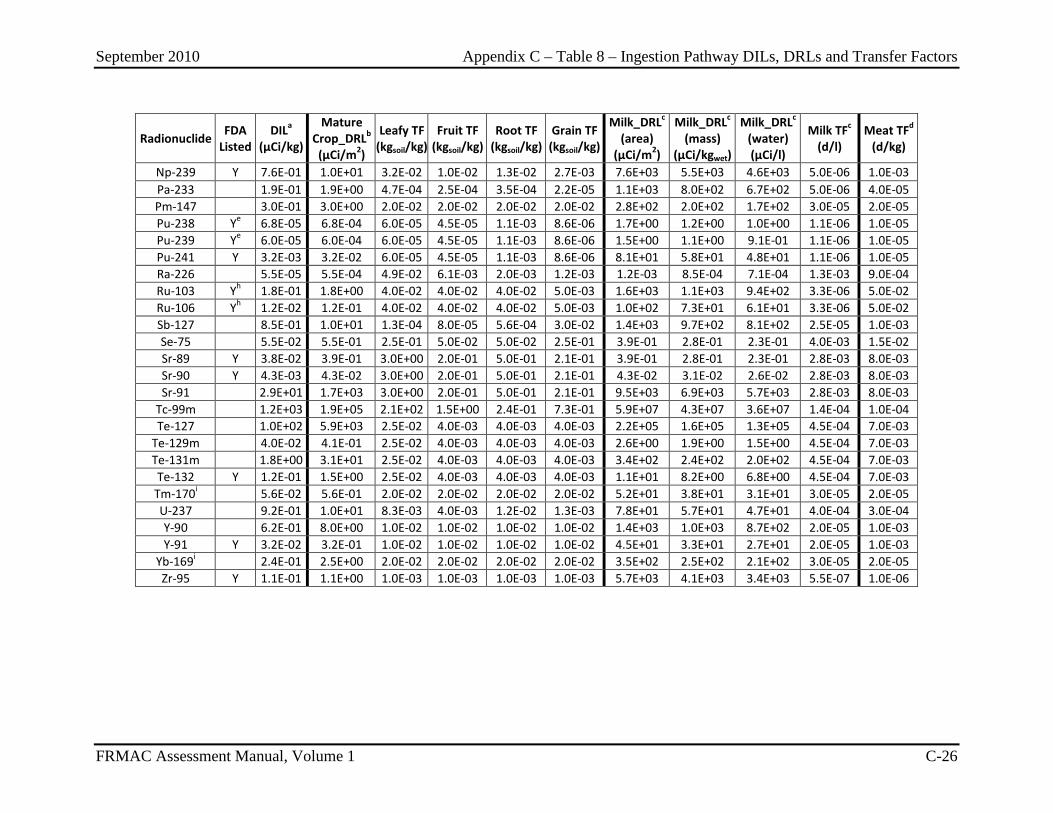
September 2010 Appendix C – Table 8 – Ingestion Pathway DILs, DRLs and Transfer Factors
FRMAC Assessment Manual, Volume 1 C-26
Radionuclide FDA Listed
DILa (µCi/kg)
Mature Crop_DRLb (µCi/m2)
Leafy TF (kgsoil/kg)
Fruit TF (kgsoil/kg)
Root TF (kgsoil/kg)
Grain TF (kgsoil/kg)
Milk_DRLc (area)
(µCi/m2)
Milk_DRLc (mass)
(µCi/kgwet)
Milk_DRLc (water) (µCi/l)
Milk TFc (d/l)
Meat TFd (d/kg)
Np-239 Y 7.6E-01 1.0E+01 3.2E-02 1.0E-02 1.3E-02 2.7E-03 7.6E+03 5.5E+03 4.6E+03 5.0E-06 1.0E-03 Pa-233 1.9E-01 1.9E+00 4.7E-04 2.5E-04 3.5E-04 2.2E-05 1.1E+03 8.0E+02 6.7E+02 5.0E-06 4.0E-05 Pm-147 3.0E-01 3.0E+00 2.0E-02 2.0E-02 2.0E-02 2.0E-02 2.8E+02 2.0E+02 1.7E+02 3.0E-05 2.0E-05 Pu-238 Ye 6.8E-05 6.8E-04 6.0E-05 4.5E-05 1.1E-03 8.6E-06 1.7E+00 1.2E+00 1.0E+00 1.1E-06 1.0E-05 Pu-239 Ye 6.0E-05 6.0E-04 6.0E-05 4.5E-05 1.1E-03 8.6E-06 1.5E+00 1.1E+00 9.1E-01 1.1E-06 1.0E-05 Pu-241 Y 3.2E-03 3.2E-02 6.0E-05 4.5E-05 1.1E-03 8.6E-06 8.1E+01 5.8E+01 4.8E+01 1.1E-06 1.0E-05 Ra-226 5.5E-05 5.5E-04 4.9E-02 6.1E-03 2.0E-03 1.2E-03 1.2E-03 8.5E-04 7.1E-04 1.3E-03 9.0E-04 Ru-103 Yh 1.8E-01 1.8E+00 4.0E-02 4.0E-02 4.0E-02 5.0E-03 1.6E+03 1.1E+03 9.4E+02 3.3E-06 5.0E-02 Ru-106 Yh 1.2E-02 1.2E-01 4.0E-02 4.0E-02 4.0E-02 5.0E-03 1.0E+02 7.3E+01 6.1E+01 3.3E-06 5.0E-02 Sb-127 8.5E-01 1.0E+01 1.3E-04 8.0E-05 5.6E-04 3.0E-02 1.4E+03 9.7E+02 8.1E+02 2.5E-05 1.0E-03 Se-75 5.5E-02 5.5E-01 2.5E-01 5.0E-02 5.0E-02 2.5E-01 3.9E-01 2.8E-01 2.3E-01 4.0E-03 1.5E-02 Sr-89 Y 3.8E-02 3.9E-01 3.0E+00 2.0E-01 5.0E-01 2.1E-01 3.9E-01 2.8E-01 2.3E-01 2.8E-03 8.0E-03 Sr-90 Y 4.3E-03 4.3E-02 3.0E+00 2.0E-01 5.0E-01 2.1E-01 4.3E-02 3.1E-02 2.6E-02 2.8E-03 8.0E-03 Sr-91 2.9E+01 1.7E+03 3.0E+00 2.0E-01 5.0E-01 2.1E-01 9.5E+03 6.9E+03 5.7E+03 2.8E-03 8.0E-03
Tc-99m 1.2E+03 1.9E+05 2.1E+02 1.5E+00 2.4E-01 7.3E-01 5.9E+07 4.3E+07 3.6E+07 1.4E-04 1.0E-04 Te-127 1.0E+02 5.9E+03 2.5E-02 4.0E-03 4.0E-03 4.0E-03 2.2E+05 1.6E+05 1.3E+05 4.5E-04 7.0E-03
Te-129m 4.0E-02 4.1E-01 2.5E-02 4.0E-03 4.0E-03 4.0E-03 2.6E+00 1.9E+00 1.5E+00 4.5E-04 7.0E-03 Te-131m 1.8E+00 3.1E+01 2.5E-02 4.0E-03 4.0E-03 4.0E-03 3.4E+02 2.4E+02 2.0E+02 4.5E-04 7.0E-03 Te-132 Y 1.2E-01 1.5E+00 2.5E-02 4.0E-03 4.0E-03 4.0E-03 1.1E+01 8.2E+00 6.8E+00 4.5E-04 7.0E-03
Tm-170i 5.6E-02 5.6E-01 2.0E-02 2.0E-02 2.0E-02 2.0E-02 5.2E+01 3.8E+01 3.1E+01 3.0E-05 2.0E-05 U-237 9.2E-01 1.0E+01 8.3E-03 4.0E-03 1.2E-02 1.3E-03 7.8E+01 5.7E+01 4.7E+01 4.0E-04 3.0E-04 Y-90 6.2E-01 8.0E+00 1.0E-02 1.0E-02 1.0E-02 1.0E-02 1.4E+03 1.0E+03 8.7E+02 2.0E-05 1.0E-03 Y-91 Y 3.2E-02 3.2E-01 1.0E-02 1.0E-02 1.0E-02 1.0E-02 4.5E+01 3.3E+01 2.7E+01 2.0E-05 1.0E-03
Yb-169i 2.4E-01 2.5E+00 2.0E-02 2.0E-02 2.0E-02 2.0E-02 3.5E+02 2.5E+02 2.1E+02 3.0E-05 2.0E-05 Zr-95 Y 1.1E-01 1.1E+00 1.0E-03 1.0E-03 1.0E-03 1.0E-03 5.7E+03 4.1E+03 3.4E+03 5.5E-07 1.0E-06
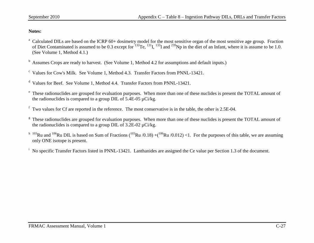
September 2010 Appendix C – Table 8 – Ingestion Pathway DILs, DRLs and Transfer Factors
FRMAC Assessment Manual, Volume 1 C-27
Notes:
a Calculated DILs are based on the ICRP 60+ dosimetry model for the most sensitive organ of the most sensitive age group. Fraction of Diet Contaminated is assumed to be 0.3 except for 132Te, 131I, 133I and 239Np in the diet of an Infant, where it is assume to be 1.0. (See Volume 1, Method 4.1.)
b Assumes Crops are ready to harvest. (See Volume 1, Method 4.2 for assumptions and default inputs.)
c Values for Cow's Milk. See Volume 1, Method 4.3. Transfer Factors from PNNL-13421.
d Values for Beef. See Volume 1, Method 4.4. Transfer Factors from PNNL-13421.
e These radionuclides are grouped for evaluation purposes. When more than one of these nuclides is present the TOTAL amount of the radionuclides is compared to a group DIL of 5.4E-05 µCi/kg.
f Two values for Cf are reported in the reference. The most conservative is in the table, the other is 2.5E-04.
g These radionuclides are grouped for evaluation purposes. When more than one of these nuclides is present the TOTAL amount of the radionuclides is compared to a group DIL of 3.2E-02 µCi/kg.
h 103Ru and 106Ru DIL is based on Sum of Fractions (103Ru /0.18) +(106Ru /0.012) <1. For the purposes of this table, we are assuming only ONE isotope is present.
i No specific Transfer Factors listed in PNNL-13421. Lanthanides are assigned the Ce value per Section 1.3 of the document.
September 2010 Appendix C – Table 8 – Ingestion Pathway DILs, DRLs and Transfer Factors
FRMAC Assessment Manual, Volume 1 C-28
This page intentionally left blank.
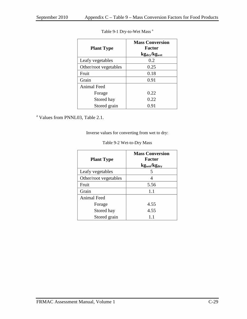
September 2010 Appendix C – Table 9 – Mass Conversion Factors for Food Products
FRMAC Assessment Manual, Volume 1 C-29
Table 9-1 Dry-to-Wet Mass a
Plant Type Mass Conversion
Factor kgdry/kgwet
Leafy vegetables 0.2 Other/root vegetables 0.25 Fruit 0.18 Grain 0.91 Animal Feed Forage 0.22 Stored hay 0.22 Stored grain 0.91
a Values from PNNL03, Table 2.1.
Inverse values for converting from wet to dry:
Table 9-2 Wet-to-Dry Mass
Plant Type Mass Conversion
Factor kgwet/kgdry
Leafy vegetables 5 Other/root vegetables 4 Fruit 5.56 Grain 1.1 Animal Feed Forage 4.55 Stored hay 4.55 Stored grain 1.1

September 2010 Appendix C – Table 9 – Mass Conversion Factors for Food Products
FRMAC Assessment Manual, Volume 1 C-30
This page intentionally left blank.
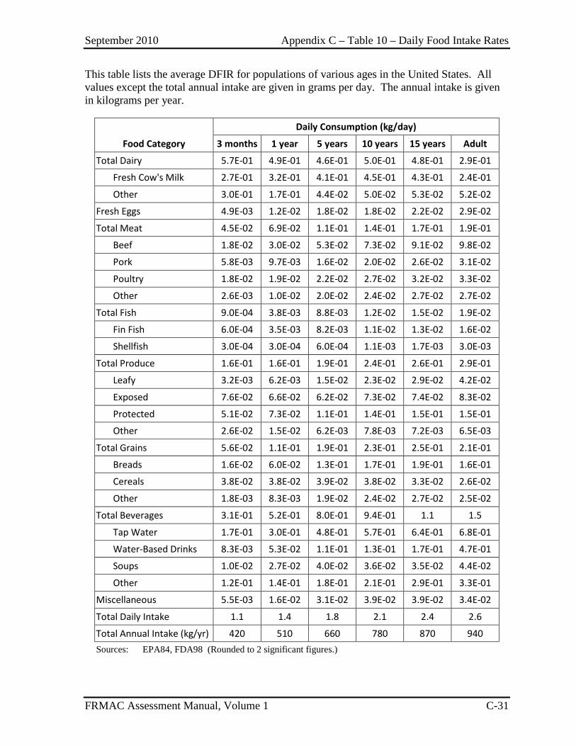
September 2010 Appendix C – Table 10 – Daily Food Intake Rates
FRMAC Assessment Manual, Volume 1 C-31
This table lists the average DFIR for populations of various ages in the United States. All values except the total annual intake are given in grams per day. The annual intake is given in kilograms per year.
Food Category
Daily Consumption (kg/day)
3 months 1 year 5 years 10 years 15 years Adult
Total Dairy 5.7E-01 4.9E-01 4.6E-01 5.0E-01 4.8E-01 2.9E-01
Fresh Cow's Milk 2.7E-01 3.2E-01 4.1E-01 4.5E-01 4.3E-01 2.4E-01
Other 3.0E-01 1.7E-01 4.4E-02 5.0E-02 5.3E-02 5.2E-02
Fresh Eggs 4.9E-03 1.2E-02 1.8E-02 1.8E-02 2.2E-02 2.9E-02
Total Meat 4.5E-02 6.9E-02 1.1E-01 1.4E-01 1.7E-01 1.9E-01
Beef 1.8E-02 3.0E-02 5.3E-02 7.3E-02 9.1E-02 9.8E-02
Pork 5.8E-03 9.7E-03 1.6E-02 2.0E-02 2.6E-02 3.1E-02
Poultry 1.8E-02 1.9E-02 2.2E-02 2.7E-02 3.2E-02 3.3E-02
Other 2.6E-03 1.0E-02 2.0E-02 2.4E-02 2.7E-02 2.7E-02
Total Fish 9.0E-04 3.8E-03 8.8E-03 1.2E-02 1.5E-02 1.9E-02
Fin Fish 6.0E-04 3.5E-03 8.2E-03 1.1E-02 1.3E-02 1.6E-02
Shellfish 3.0E-04 3.0E-04 6.0E-04 1.1E-03 1.7E-03 3.0E-03
Total Produce 1.6E-01 1.6E-01 1.9E-01 2.4E-01 2.6E-01 2.9E-01
Leafy 3.2E-03 6.2E-03 1.5E-02 2.3E-02 2.9E-02 4.2E-02
Exposed 7.6E-02 6.6E-02 6.2E-02 7.3E-02 7.4E-02 8.3E-02
Protected 5.1E-02 7.3E-02 1.1E-01 1.4E-01 1.5E-01 1.5E-01
Other 2.6E-02 1.5E-02 6.2E-03 7.8E-03 7.2E-03 6.5E-03
Total Grains 5.6E-02 1.1E-01 1.9E-01 2.3E-01 2.5E-01 2.1E-01
Breads 1.6E-02 6.0E-02 1.3E-01 1.7E-01 1.9E-01 1.6E-01
Cereals 3.8E-02 3.8E-02 3.9E-02 3.8E-02 3.3E-02 2.6E-02
Other 1.8E-03 8.3E-03 1.9E-02 2.4E-02 2.7E-02 2.5E-02
Total Beverages 3.1E-01 5.2E-01 8.0E-01 9.4E-01 1.1 1.5
Tap Water 1.7E-01 3.0E-01 4.8E-01 5.7E-01 6.4E-01 6.8E-01
Water-Based Drinks 8.3E-03 5.3E-02 1.1E-01 1.3E-01 1.7E-01 4.7E-01
Soups 1.0E-02 2.7E-02 4.0E-02 3.6E-02 3.5E-02 4.4E-02
Other 1.2E-01 1.4E-01 1.8E-01 2.1E-01 2.9E-01 3.3E-01
Miscellaneous 5.5E-03 1.6E-02 3.1E-02 3.9E-02 3.9E-02 3.4E-02
Total Daily Intake 1.1 1.4 1.8 2.1 2.4 2.6
Total Annual Intake (kg/yr) 420 510 660 780 870 940 Sources: EPA84, FDA98 (Rounded to 2 significant figures.)

September 2010 Appendix C – Table 10 – Daily Food Intake Rates
FRMAC Assessment Manual, Volume 1 C-32
This page intentionally left blank.

September 2010 Appendix C – Table 11 – Ingestion Pathway Default Assumptions
FRMAC Assessment Manual, Volume 1 C-33
The parameters in this table can vary depending on several environmental factors. The FRMAC Assessment Working Group has determined that these values are reasonable over a wide variety of conditions and should be used as the defaults for the methods in this Manual.
Parameter Description Value a
Animal Feed Daily Ingestion Rate (AFDIR)
Milk Cow 50 kg/d Beef Cattle 50 kg/d Goat 6 kg/d
Animal Soil Daily Ingestion Rate (ASDIR)
Milk Cow 0.5 kg/d b Beef Cattle 0.5 kg/d b Goat 0.06 kg/d b,c
Animal Water Daily Ingestion Rate (AWDIR)
Milk Cow 60 l/d Beef Cattle 50 l/d Goat 8 l/d
Crop Retention Factor (CRF)
Pastureland 0.5 d Pastureland, Iodines 1.0 Fresh produce, particulates 0.2 Fresh produce, Iodines 1.0 Crops planted AFTER deposition 0.0
Time to Market (tm)
Crop/Produce 1 d Milk 2 d Meat 20 d
Crop Yield (Y)
Produce 2.0 kg/m2 Pastureland 0.7 kg/m2
Crop Weathering Half life (t1/2)
15 d e
a All values from NRC77 unless otherwise indicated. b ANL01 c Goat value estimated based on ratio of Feed to Soil for Cows (100:1). d Ng77 (Appendix B, page 113) e NCRP07 (Page 165)
September 2010 Appendix C – Table 11 – Ingestion Pathway Default Assumptions
FRMAC Assessment Manual, Volume 1 C-34
This page intentionally left blank.
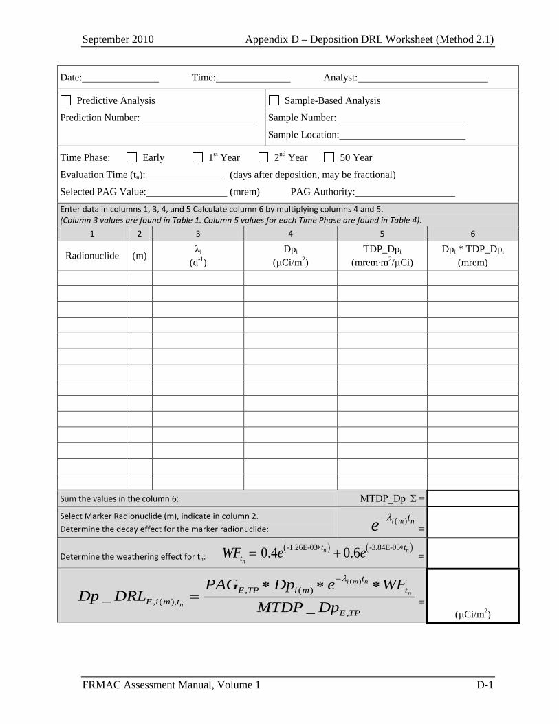
September 2010 Appendix D – Deposition DRL Worksheet (Method 2.1)
FRMAC Assessment Manual, Volume 1 D-1
Date: Time: Analyst:
Predictive Analysis
Prediction Number:
Sample-Based Analysis
Sample Number:
Sample Location:
Time Phase: Early 1st Year 2nd Year 50 Year
Evaluation Time (tn): (days after deposition, may be fractional)
Selected PAG Value: (mrem) PAG Authority:
Enter data in columns 1, 3, 4, and 5 Calculate column 6 by multiplying columns 4 and 5. (Column 3 values are found in Table 1. Column 5 values for each Time Phase are found in Table 4).
1 2 3 4 5 6
Radionuclide (m) λi
(d-1) Dpi
(µCi/m2) TDP_Dpi
(mrem·m2/µCi) Dpi * TDP_Dpi
(mrem)
Sum the values in the column 6: MTDP_Dp Σ =
Select Marker Radionuclide (m), indicate in column 2. Determine the decay effect for the marker radionuclide:
( )i m nte λ−=
Determine the weathering effect for tn: ( ) ( )-1.26E-03 -3.84E-050.4 0.6n n
n
t ttWF e e∗ ∗= + =
( ), ( )
, ( ),,
__
i m n
n
n
tE TP i m t
E i m tE TP
PAG Dp e WFDp DRL
MTDP Dp
λ−∗ ∗ ∗= =
(µCi/m2)

September 2010 Appendix D – Deposition Dose and Exposure Rate DRL Worksheet (Method 2.2)
FRMAC Assessment Manual, Volume 1 D-2
Date: Time: Analyst:
Predictive Analysis
Prediction Number:
Sample-Based Analysis
Sample Number:
Sample Location:
Time Phase: Early 1st Year 2nd Year 50 Year Evaluation Time (tn): (days after deposition, may be fractional)
Selected PAG Value: (mrem) PAG Authority: XDCF: (mrem/mR)
Enter data in columns 1, 2, 3, 5, and 7. Calculate column 4 by multiplying columns 2 and 3. Calculate column 8 by multiplying columns 2, 6, and 7. (Column 3 and 7 values for each Time Phase are found in Table 4. Column 5 values are found in Table 1.)
1 2 3 4 5 6 7 8
Radionuclide Dpi
(µCi/m2) TDP_Dpi
(mrem·m2/µCi) Dpi * TDP_Dpi
(mrem) λi
(d-1) i nte λ−
ExDFi
(mrem·m2/hr·µCi) Dpi * e-λt * ExDFi
(mrem/hr)
Sum values in column 4: MTDP_Dp = Sum the values in column 8: ∑=
Determine the weathering effect for tn: ( ) ( )-1.26E-03 -3.84E-050.4 0.6n n
n
t ttWF e e∗ ∗= + = Multiply WF by above ∑:
MExDF_Dpi =
,
,
__ E tn
E tn
DRXR
Dp DRLDp DRL
XDCF= =
(mR/hr) ,
,,
,
__
_n
E tn
E tDR E TP
E TP
MExDF DpDp DRL PAG
MTDP Dp= ∗ =
(mrem/hr)
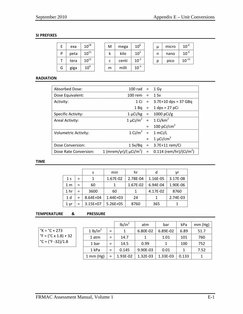
September 2010 Appendix E – Unit Conversions
FRMAC Assessment Manual, Volume 1 E-1
SI PREFIXES
E exa 1018 M mega 106 μ micro 10-6
P peta 1015 k kilo 103 n nano 10-9
T tera 1012 c centi 10-2 p pico 10-12
G giga 109 m milli 10-3
RADIATION
Absorbed Dose: 100 rad = 1 Gy Dose Equivalent: 100 rem = 1 Sv Activity: 1 Ci = 3.7E+10 dps = 37 GBq 1 Bq = 1 dps = 27 pCi Specific Activity: 1 µCi/kg = 1000 pCi/g Areal Activity: 1 µCi/m2 = 1 Ci/km2 = 100 pCi/cm2 Volumetric Activity: 1 Ci/m3 = 1 mCi/L = 1 µCi/cm3 Dose Conversion: 1 Sv/Bq = 3.7E+11 rem/Ci Dose Rate Conversion: 1 (mrem/yr)/( µCi/m2) = 0.114 (rem/hr)/(Ci/m2)
TIME
s min hr d yr 1 s = 1 1.67E-02 2.78E-04 1.16E-05 3.17E-08 1 m = 60 1 1.67E-02 6.94E-04 1.90E-06 1 hr = 3600 60 1 4.17E-02 8760 1 d = 8.64E+04 1.44E+03 24 1 2.74E-03 1 yr = 3.15E+07 5.26E+05 8760 365 1
TEMPERATURE & PRESSURE
lb/in2 atm bar kPa mm (Hg) °K = °C + 273 °F = (°C x 1.8) + 32 °C = (°F -32)/1.8
1 lb/in2 = 1 6.80E-02 6.89E-02 6.89 51.7 1 atm = 14.7 1 1.01 101 760 1 bar = 14.5 0.99 1 100 752
1 kPa = 0.145 9.90E-03 0.01 1 7.52 1 mm (Hg) = 1.93E-02 1.32E-03 1.33E-03 0.133 1
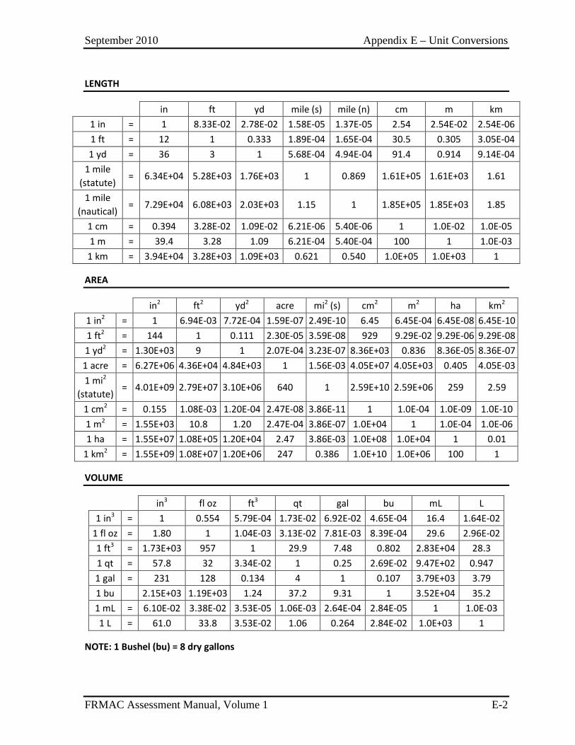
September 2010 Appendix E – Unit Conversions
FRMAC Assessment Manual, Volume 1 E-2
LENGTH
in ft yd mile (s) mile (n) cm m km 1 in = 1 8.33E-02 2.78E-02 1.58E-05 1.37E-05 2.54 2.54E-02 2.54E-06 1 ft = 12 1 0.333 1.89E-04 1.65E-04 30.5 0.305 3.05E-04 1 yd = 36 3 1 5.68E-04 4.94E-04 91.4 0.914 9.14E-04
1 mile (statute)
= 6.34E+04 5.28E+03 1.76E+03 1 0.869 1.61E+05 1.61E+03 1.61
1 mile (nautical)
= 7.29E+04 6.08E+03 2.03E+03 1.15 1 1.85E+05 1.85E+03 1.85
1 cm = 0.394 3.28E-02 1.09E-02 6.21E-06 5.40E-06 1 1.0E-02 1.0E-05 1 m = 39.4 3.28 1.09 6.21E-04 5.40E-04 100 1 1.0E-03
1 km = 3.94E+04 3.28E+03 1.09E+03 0.621 0.540 1.0E+05 1.0E+03 1
AREA
in2 ft2 yd2 acre mi2 (s) cm2 m2 ha km2 1 in2 = 1 6.94E-03 7.72E-04 1.59E-07 2.49E-10 6.45 6.45E-04 6.45E-08 6.45E-10 1 ft2 = 144 1 0.111 2.30E-05 3.59E-08 929 9.29E-02 9.29E-06 9.29E-08 1 yd2 = 1.30E+03 9 1 2.07E-04 3.23E-07 8.36E+03 0.836 8.36E-05 8.36E-07 1 acre = 6.27E+06 4.36E+04 4.84E+03 1 1.56E-03 4.05E+07 4.05E+03 0.405 4.05E-03 1 mi2
(statute) = 4.01E+09 2.79E+07 3.10E+06 640 1 2.59E+10 2.59E+06 259 2.59
1 cm2 = 0.155 1.08E-03 1.20E-04 2.47E-08 3.86E-11 1 1.0E-04 1.0E-09 1.0E-10 1 m2 = 1.55E+03 10.8 1.20 2.47E-04 3.86E-07 1.0E+04 1 1.0E-04 1.0E-06 1 ha = 1.55E+07 1.08E+05 1.20E+04 2.47 3.86E-03 1.0E+08 1.0E+04 1 0.01
1 km2 = 1.55E+09 1.08E+07 1.20E+06 247 0.386 1.0E+10 1.0E+06 100 1
VOLUME
in3 fl oz ft3 qt gal bu mL L 1 in3 = 1 0.554 5.79E-04 1.73E-02 6.92E-02 4.65E-04 16.4 1.64E-02
1 fl oz = 1.80 1 1.04E-03 3.13E-02 7.81E-03 8.39E-04 29.6 2.96E-02 1 ft3 = 1.73E+03 957 1 29.9 7.48 0.802 2.83E+04 28.3 1 qt = 57.8 32 3.34E-02 1 0.25 2.69E-02 9.47E+02 0.947 1 gal = 231 128 0.134 4 1 0.107 3.79E+03 3.79 1 bu 2.15E+03 1.19E+03 1.24 37.2 9.31 1 3.52E+04 35.2 1 mL = 6.10E-02 3.38E-02 3.53E-05 1.06E-03 2.64E-04 2.84E-05 1 1.0E-03 1 L = 61.0 33.8 3.53E-02 1.06 0.264 2.84E-02 1.0E+03 1
NOTE: 1 Bushel (bu) = 8 dry gallons
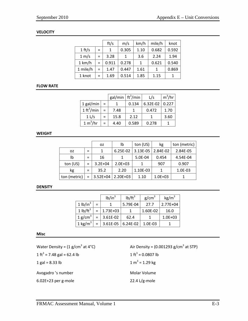
September 2010 Appendix E – Unit Conversions
FRMAC Assessment Manual, Volume 1 E-3
VELOCITY
ft/s m/s km/h mile/h knot 1 ft/s = 1 0.305 1.10 0.682 0.592 1 m/s = 3.28 1 3.6 2.24 1.94
1 km/h = 0.911 0.278 1 0.621 0.540 1 mile/h = 1.47 0.447 1.61 1 0.869 1 knot = 1.69 0.514 1.85 1.15 1
FLOW RATE
gal/min ft3/min L/s m3/hr 1 gal/min = 1 0.134 6.32E-02 0.227 1 ft3/min = 7.48 1 0.472 1.70
1 L/s = 15.8 2.12 1 3.60 1 m3/hr = 4.40 0.589 0.278 1
WEIGHT
oz lb ton (US) kg ton (metric) oz = 1 6.25E-02 3.13E-05 2.84E-02 2.84E-05 lb = 16 1 5.0E-04 0.454 4.54E-04
ton (US) = 3.2E+04 2.0E+03 1 907 0.907 kg = 35.2 2.20 1.10E-03 1 1.0E-03
ton (metric) = 3.52E+04 2.20E+03 1.10 1.0E+03 1
DENSITY
lb/in3 lb/ft3 g/cm3 kg/m3 1 lb/in3 = 1 5.79E-04 27.7 2.77E+04 1 lb/ft3 = 1.73E+03 1 1.60E-02 16.0 1 g/cm3 = 3.61E-02 62.4 1 1.0E+03 1 kg/m3 = 3.61E-05 6.24E-02 1.0E-03 1
Misc
Water Density = (1 g/cm3 at 4°C)
1 ft3 = 7.48 gal = 62.4 lb
1 gal = 8.33 lb
Air Density = (0.001293 g/cm3 at STP)
1 ft3 = 0.0807 lb
1 m3 = 1.29 kg
Avogadro ’s number
6.02E+23 per g-mole
Molar Volume
22.4 L/g-mole

September 2010 Appendix E – Unit Conversions
FRMAC Assessment Manual, Volume 1 E-4
This page intentionally left blank.
September 2010 Appendix F – Supplemental Information
FRMAC Assessment Manual, Volume 1 F-1
SUPPLEMENTS
Effective Date
Supplement 1: Decay and Ingrowth Calculation .................................... F.1-1 9/2010
Supplement 2: Calculation of Resuspension and Combined Removal Parameters ...................................................................... F.2-1 9/2010

September 2010 Appendix F – Supplemental Information
FRMAC Assessment Manual, Volume 1 F-2
This page intentionally left blank.

September 2010 Appendix F – Supplement 1 – Decay and In-growth Calculations
FRMAC Assessment Manual, Volume 1 F.1-1
SUPPLEMENT 1 – DECAY AND IN-GROWTH CALCULATIONS
The default assessment methods presented in this manual implement restrictive daughter inclusion rules and make the assumption that the radionuclide mixture is in transient/secular equilibrium. These assumptions simplify the calculation of each radionuclide’s activity in the mixture at the evaluation time (tn). Although these simplifying assumptions work well for many radionuclide chains, they are not ideal in all cases.
In order to model complex decay chains more completely, the Bateman equations (H. Bateman, “Solution of a System of Differential Equations Occurring in the Theory of Radioactive Transformations,” Proc. Cambridge Phil. Soc. IS, 423 (1910)) are used to determine the amount of a radionuclide present at the evaluation time (tn) based on the decay and in-growth of all radionuclides present in the mixture. A general overview of the calculations is presented below.
To perform this calculation, it is necessary to evaluate the production and decay of each radionuclide in the chain to determine the total amount of each radionuclide present at the evaluation time (tn). For example, in a 3-nuclide chain:
The activity of the parent radionuclide at tn is:
, ,0λ−= ∗ p n
n
tp t pA A e (Eq. 1)
The activity of its first generation daughter, including Branching Ratio (BrRd1), at tn is:
( )1
1 1 1
1
, ,0
λλ
λλ λ
−− −= ∗ ∗ ∗ −
d np n
n
tt
d t p d dd p
e eA A BrR (Eq. 2)
The activity of its second generation daughter, including Branching Ratio (BrRd2), at tn is:
( )
( )( ) ( )( ) ( )( )
2 1 1 2 2
1 2
1 2 1 2 1 2 1 2
, ,0
λ λλ
λ λ
λ λ λ λ λ λ λ λ λ λ λ λ
− −−
= ∗ ∗ ∗ ∗
∗ + +
− − − − − −
n
d n d np n
d t p d d d d
t tt
d p d p p d d d p d d d
A A BrR BrR
e e e (Eq. 3)
Because this second generation daughter (d2) is the first generation daughter of radionuclide d1, the activity of d2 at tn due to the initial amount of d1 can be determined from equation 3 as:
( )1 2
2 1 2 2
2 1
, ,0
λ λ
λλ λ
− − −= ∗ ∗ ∗ −
d n d n
n
t t
d t d d dd d
e eA A BrR (Eq. 4)
The activity of d2 as a parent at tn is:
2
2 2, ,0λ−= ∗ d n
n
td t dA A e (Eq. 5)
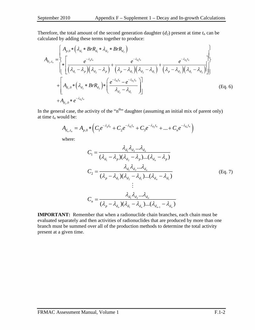
September 2010 Appendix F – Supplement 1 – Decay and In-growth Calculations
FRMAC Assessment Manual, Volume 1 F.1-2
Therefore, the total amount of the second generation daughter (d2) present at time tn can be calculated by adding these terms together to produce:
( )
( )( ) ( )( ) ( )( )
( )
1 1 2 2
1 22
1 2 1 2 1 2 1 2
1 2
1 2 2
2 1
2
2
,0
,
,0
,0
λ λλ
λ λ
λ
λ λ
λ λ λ λ λ λ λ λ λ λ λ λ
λλ λ
− −−
− −
−
∗ ∗ ∗ ∗ = ∗ + +
− − − − − − −
+ ∗ ∗ ∗ −
+ ∗
d n d np nn
d n d n
d n
p d d d d
t ttd t
d p d p p d d d p d d d
t t
d d dd d
td
A BrR BrR
A e e e
e eA BrR
A e
(Eq. 6)
In the general case, the activity of the “nth” daughter (assuming an initial mix of parent only) at time tn would be:
( )1 2
1 2
1 2
1 2
1 2 1 1
1 2
1 1
, ,0 1 2 3
1
2
where:
...
...( )( )...( )
...( )( )...( )
...( )( )...( )
λλ λλ
λ λ λλ λ λ λ λ λ
λ λ λλ λ λ λ λ λ
λ λ λλ λ λ λ λ λ
−
−− −−= ∗ + + + +
=− − −
=− − −
=− − −
d nd n d np n n
n n
n
n
n
n
n
n n n n
tt ttd t p n
d d d
d p d p d p
d d d
p d d d d d
d d dn
p d d d d d
A A C e C e C e C e
C
C
C
(Eq. 7)
IMPORTANT: Remember that when a radionuclide chain branches, each chain must be evaluated separately and then activities of radionuclides that are produced by more than one branch must be summed over all of the production methods to determine the total activity present at a given time.
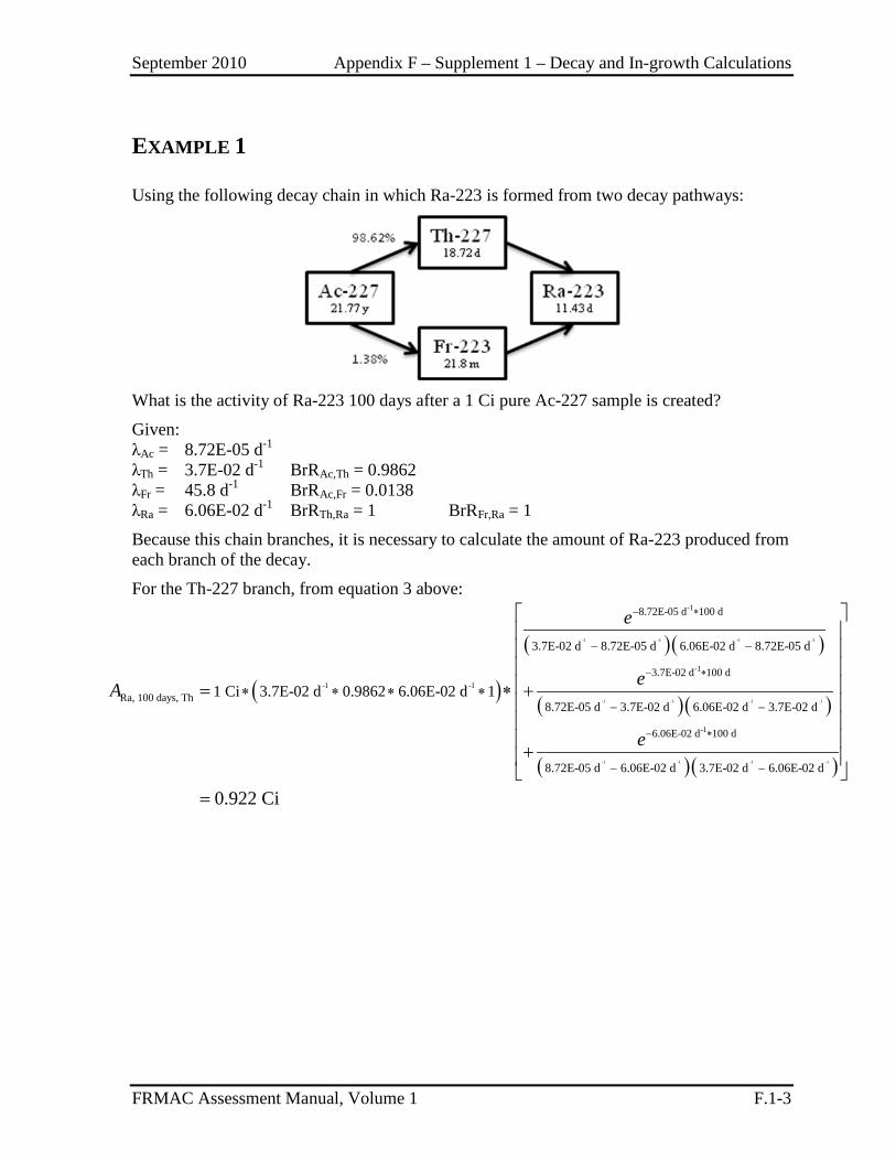
September 2010 Appendix F – Supplement 1 – Decay and In-growth Calculations
FRMAC Assessment Manual, Volume 1 F.1-3
EXAMPLE 1
Using the following decay chain in which Ra-223 is formed from two decay pathways:
What is the activity of Ra-223 100 days after a 1 Ci pure Ac-227 sample is created?
Given: λAc = 8.72E-05 d-1 λTh = 3.7E-02 d-1 BrRAc,Th = 0.9862 λFr = 45.8 d-1 BrRAc,Fr = 0.0138 λRa = 6.06E-02 d-1 BrRTh,Ra = 1 BrRFr,Ra = 1
Because this chain branches, it is necessary to calculate the amount of Ra-223 produced from each branch of the decay.
For the Th-227 branch, from equation 3 above:
( )
( )( )
( )( )
-1 -1 -1 -1
-1 -1 -1 -1
-1 -1
-1
-1
8.72E-05 d 100 d
3.7E-02 d 100 d
Ra, 100 days, Th
6.0
3.7E-02 d 8.72E-05 d 6.06E-02 d 8.72E-05 d
8.72E-05 d 3.7E-02 d 6.06E-02 d 3.7E-02 d1 Ci 3.7E-02 d 0.9862 6.06E-02 d 1
− ∗
− ∗
−
− −
− −∗ ∗ ∗ ∗= ∗ +
+
e
eA
e( )( )-1 -1 -1 -1
-16E-02 d 100 d
8.72E-05 d 6.06E-02 d 3.7E-02 d 6.06E-02 d
0.922 Ci
∗
− −
=
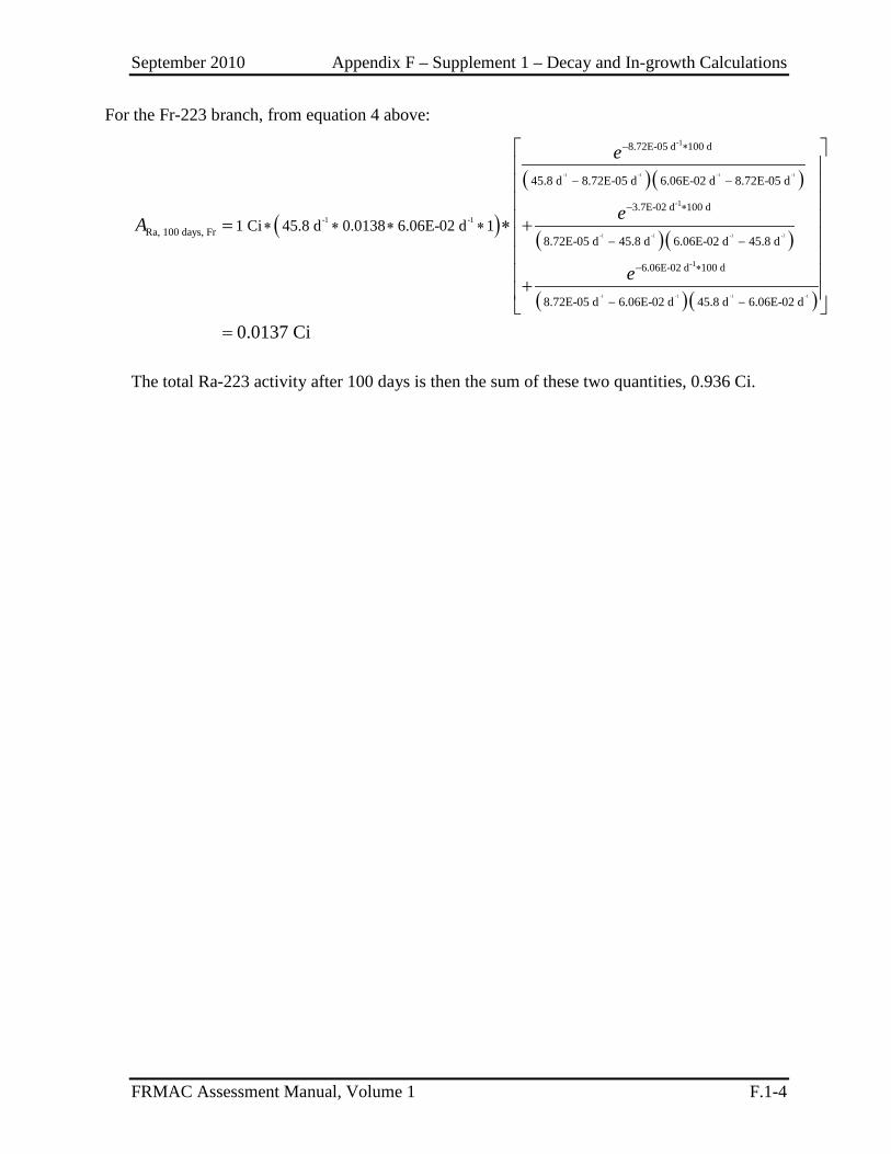
September 2010 Appendix F – Supplement 1 – Decay and In-growth Calculations
FRMAC Assessment Manual, Volume 1 F.1-4
For the Fr-223 branch, from equation 4 above:
( )
( )( )
( )( )
-1 -1 -1 -1
-1 -1 -1 -1
-1 -1
-1
-1
-1
8.72E-05 d 100 d
3.7E-02 d 100 d
Ra, 100 days, Fr
6.06E-02 d 10
45.8 d 8.72E-05 d 6.06E-02 d 8.72E-05 d
8.72E-05 d 45.8 d 6.06E-02 d 45.8 d1 Ci 45.8 d 0.0138 6.06E-02 d 1
− ∗
− ∗
− ∗
− −
− −∗ ∗ ∗ ∗= ∗ +
+
e
eA
e( )( )-1 -1 -1 -1
0 d
8.72E-05 d 6.06E-02 d 45.8 d 6.06E-02 d
0.0137 Ci
− −
=
The total Ra-223 activity after 100 days is then the sum of these two quantities, 0.936 Ci.
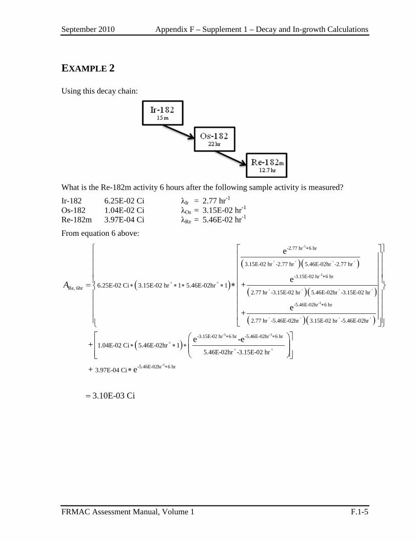
September 2010 Appendix F – Supplement 1 – Decay and In-growth Calculations
FRMAC Assessment Manual, Volume 1 F.1-5
EXAMPLE 2
Using this decay chain:
What is the Re-182m activity 6 hours after the following sample activity is measured?
Ir-182 6.25E-02 Ci λIr = 2.77 hr-1 Os-182 1.04E-02 Ci λOs = 3.15E-02 hr-1 Re-182m 3.97E-04 Ci λRe = 5.46E-02 hr-1
From equation 6 above:
( )
( )( )
( )( )
-1 -1 -1 -1
-1 -1 -1 -1
-1 -1
-1
-1
-1
-2.77 hr 6 hr
-3.15E-02 hr 6 hr
Re, 6hr
-5.46E-02hr 6
3.15E-02 hr -2.77 hr 5.46E-02hr -2.77 hr
2.77 hr -3.15E-02 hr 5.46E-02hr -3.15E-02 hr6.25E-02 Ci 3.15E-02 hr 1 5.46E-02hr 1
e
e+
e+
∗
∗
∗
∗ ∗ ∗ ∗= ∗A
( )( )
( )
-1 -1 -1 -1
-1
-1 -1
-1 -1
hr
-3.15E-02 hr 6 hr -5.46E-02hr 6 hr
2.77 hr -5.46E-02hr 3.15E-02 hr -5.46E-02hr
1.04E-02 Ci 5.46E-02hr 15.46E-02hr -3.15E-02 hr
e -e+∗ ∗
∗ ∗ ∗
-1-5.46E-02hr 6 hr3.97E-04 Ci+ e
3.10E-03 Ci
∗∗
=
September 2010 Appendix F – Supplement 1 – Decay and In-growth Calculations
FRMAC Assessment Manual, Volume 1 F.1-6
This page intentionally left blank.
September 2010 Appendix F – Supplement 2 – Calculation of KP and CRP
FRMAC Assessment Manual, Volume 1 F.2-1
SUPPLEMENT 2 – CALCULATION OF RESUSPENSION AND COMBINED REMOVAL PARAMETERS
Several assessment methods rely on the time-dependent integrated quantities which require complex math to calculate. In order to avoid lengthy diversions away from the health physics behind the methods (which would need to be repeated at several locations in the manual) the detailed derivations of these terms have been placed here.
This supplement addresses the calculation of the following quantities:
KPi, TP = Resuspension Parameter, value that adjusts the airborne radioactivity level of radionuclide i over the time phase (TP) under consideration for radioactive decay and the time-dependent resuspension factor (K) (value obtained numerically from Turbo FRMAC), s/m;
CRPi, TP = Combined Removal Parameter, value that adjusts for radioactive decay and weathering effects that decrease the amount of radionuclide i available to cause direct exposure or to be ingested over the time phase (TP) under consideration, s;
WF = Weathering Factor, value that adjusts the groundshine dose for weathering forces that reduce the radionuclide activity near the surface and thereby decrease the external dose rate, unitless;
NOTE: Weathering is used in this manual both as a contributor to the Combined Removal Parameter and as an independent factor. This Supplement treats Weathering as a contributor to the CRP. If a calculation involves weathering as an independent factor the section on Weathering may be performed as a stand-alone calculation.
Resuspension Parameter
The Resuspension Parameter (KP) adjusts the inhalation dose for radioactive decay (e-λt) and the time-dependent Resuspension Factor (K) over the time phase under consideration.
NOTE: This KP model is the default approach, but may not be appropriate for the environmental conditions existing in the area under investigation. An alternate KP model may be substituted, with approval from local authorities, if the alternate model can be shown to more accurately model the weathering in the area under investigation.
The KP integral below does not have an exact solution when K is in a time-dependent form (as in the standard approach used here). Therefore the integral cannot be solved analytically and must be solved using a software program that is capable of numerical integration.
2
1
-,
i
tt
i TPt
KP K e dtλ= ∗∫ (Eq. 1)
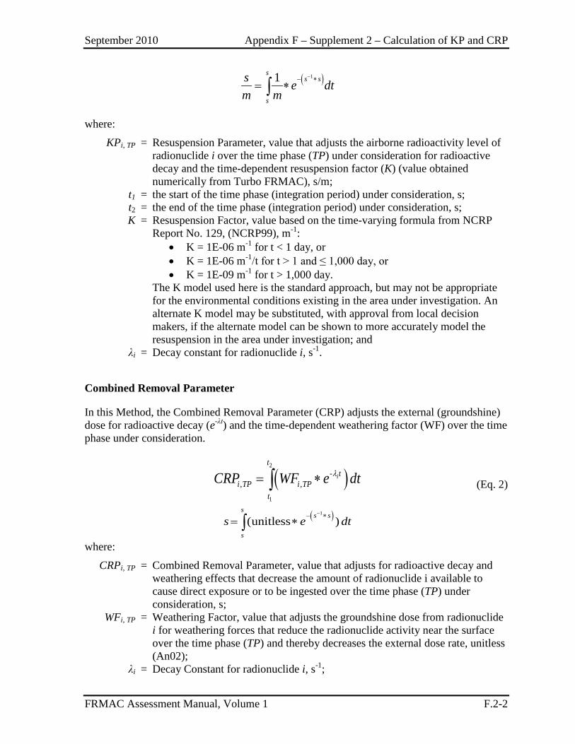
September 2010 Appendix F – Supplement 2 – Calculation of KP and CRP
FRMAC Assessment Manual, Volume 1 F.2-2
( )11ss s
s
s e dtm m
−− ∗= ∗∫
where:
KPi, TP = Resuspension Parameter, value that adjusts the airborne radioactivity level of radionuclide i over the time phase (TP) under consideration for radioactive decay and the time-dependent resuspension factor (K) (value obtained numerically from Turbo FRMAC), s/m;
t1 = the start of the time phase (integration period) under consideration, s; t2 = the end of the time phase (integration period) under consideration, s; K = Resuspension Factor, value based on the time-varying formula from NCRP
Report No. 129, (NCRP99), m-1: • K = 1E-06 m-1 for t < 1 day, or • K = 1E-06 m-1/t for t > 1 and ≤ 1,000 day, or • K = 1E-09 m-1 for t > 1,000 day.
The K model used here is the standard approach, but may not be appropriate for the environmental conditions existing in the area under investigation. An alternate K model may be substituted, with approval from local decision makers, if the alternate model can be shown to more accurately model the resuspension in the area under investigation; and
λi = Decay constant for radionuclide i, s-1.
Combined Removal Parameter
In this Method, the Combined Removal Parameter (CRP) adjusts the external (groundshine) dose for radioactive decay (e-λt) and the time-dependent weathering factor (WF) over the time phase under consideration.
( )2
1
-, ,
i
tt
i TP i TPt
CRP WF e dtλ= ∗∫ (Eq. 2)
( )1
(unitless )s
s s
s
s e dt−− ∗
= ∗∫
where:
CRPi, TP = Combined Removal Parameter, value that adjusts for radioactive decay and weathering effects that decrease the amount of radionuclide i available to cause direct exposure or to be ingested over the time phase (TP) under consideration, s;
WFi, TP = Weathering Factor, value that adjusts the groundshine dose from radionuclide i for weathering forces that reduce the radionuclide activity near the surface over the time phase (TP) and thereby decreases the external dose rate, unitless (An02);
λi = Decay Constant for radionuclide i, s-1;
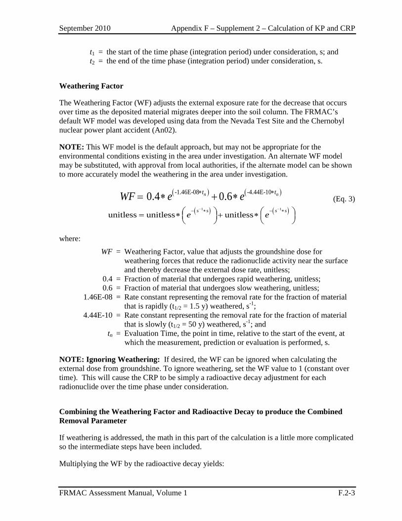
September 2010 Appendix F – Supplement 2 – Calculation of KP and CRP
FRMAC Assessment Manual, Volume 1 F.2-3
t1 = the start of the time phase (integration period) under consideration, s; and t2 = the end of the time phase (integration period) under consideration, s.
Weathering Factor
The Weathering Factor (WF) adjusts the external exposure rate for the decrease that occurs over time as the deposited material migrates deeper into the soil column. The FRMAC’s default WF model was developed using data from the Nevada Test Site and the Chernobyl nuclear power plant accident (An02).
NOTE: This WF model is the default approach, but may not be appropriate for the environmental conditions existing in the area under investigation. An alternate WF model may be substituted, with approval from local authorities, if the alternate model can be shown to more accurately model the weathering in the area under investigation.
( ) ( )-1.46E-08 -4.44E-100.4 0.6n nt tWF e e∗ ∗= ∗ + ∗ (Eq. 3)
( ) ( )1 1
unitless unitless unitlesss s s se e− −− ∗ − ∗ = ∗ + ∗
where:
WF = Weathering Factor, value that adjusts the groundshine dose for weathering forces that reduce the radionuclide activity near the surface and thereby decrease the external dose rate, unitless;
0.4 = Fraction of material that undergoes rapid weathering, unitless; 0.6 = Fraction of material that undergoes slow weathering, unitless; 1.46E-08 = Rate constant representing the removal rate for the fraction of material
that is rapidly (t1/2 = 1.5 y) weathered, s-1; 4.44E-10 = Rate constant representing the removal rate for the fraction of material
that is slowly (t1/2 = 50 y) weathered, s-1; and tn = Evaluation Time, the point in time, relative to the start of the event, at
which the measurement, prediction or evaluation is performed, s.
NOTE: Ignoring Weathering: If desired, the WF can be ignored when calculating the external dose from groundshine. To ignore weathering, set the WF value to 1 (constant over time). This will cause the CRP to be simply a radioactive decay adjustment for each radionuclide over the time phase under consideration.
Combining the Weathering Factor and Radioactive Decay to produce the Combined Removal Parameter
If weathering is addressed, the math in this part of the calculation is a little more complicated so the intermediate steps have been included.
Multiplying the WF by the radioactive decay yields:
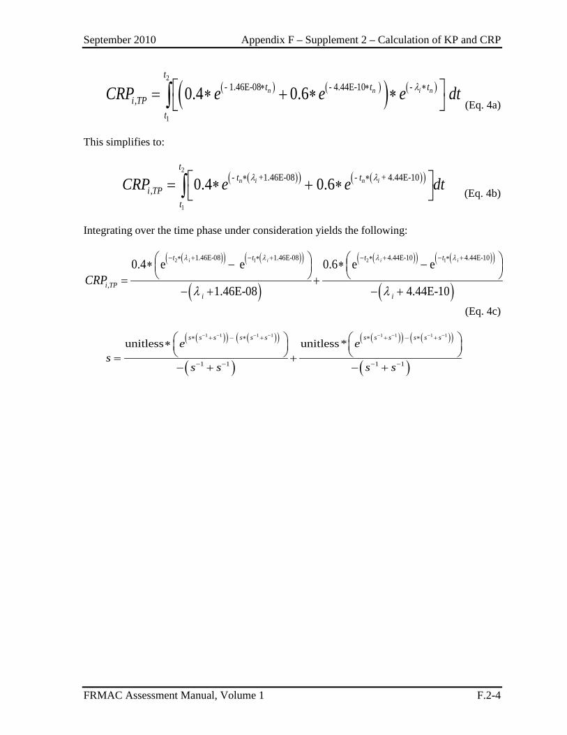
September 2010 Appendix F – Supplement 2 – Calculation of KP and CRP
FRMAC Assessment Manual, Volume 1 F.2-4
( ) ( )( ) ( )
2
1
- 1.46E-08 - 4.44E-10 - , 0.4 0.6n n i n
tt t t
i TPt
CRP e e e dtλ∗ ∗ ∗ = ∗ + ∗ ∗ ∫ (Eq. 4a)
This simplifies to:
( )( ) ( )( )
2
1
- +1.46E-08 - + 4.44E-10, 0.4 0.6n i n i
tt t
i TPt
CRP e e dtλ λ∗ ∗ = ∗ + ∗ ∫ (Eq. 4b)
Integrating over the time phase under consideration yields the following:
( )( ) ( )( )
( )
( )( ) ( )( )
( )
2 1 2 11.46E-08 1.46E-08 4.44E-10 4.44E-10
,
0.4 e e 0.6 e e
1.46E-08 4.44E-10
i i i it t t t
i TPi i
CRP
λ λ λ λ
λ λ
− ∗ + − ∗ + − ∗ + − ∗ + ∗ − ∗ − = +
− + − + (Eq. 4c)
( )( ) ( )( )
( )
( )( ) ( )( )
( )
1 1 1 1 1 1 1 1
1 1 1 1
unitless unitless*s s s s s s s s s s s s
e es
s s s s
− − − − − − − −∗ + − ∗ + ∗ + − ∗ +
− − − −
∗ = +− + − +
September 2010 Appendix G – References
FRMAC Assessment Manual, Volume 1 G-1
Reference Title 10 CFR 20 Standards for Protection Against Radiation, Code of Federal Regulations,
Title 10, Energy, Part 20. An02 Anspaugh, L. R., et al., “Movement of Radionuclides in Terrestrial
Exosystems by Physical Processes” in Health Physics, Vol. 82, pp. 670-679, April 2002.
ANL01 Yu, C., et al., User's Manual for RESRAD, ver. 6, Argonne National Laboratory, Argonne, IL, 2001.
DCFPAK Eckerman, K., et al., Dose Coefficient Factor Package, Oak Ridge National Laboratory, Oak Ridge, TN, 1996 - current version.
DHS08 Planning Guidance for Protection and Recovery Following Radiological Dispersal Device and Improvised Nuclear Device Incidents, U.S. Department of Homeland Security, Washington, DC, Federal Register, August 1, 2008.
DNA75 Place, W. M., Cobb, F. C., and Defferding, C. G., Palomares Summary Report, AD-A955702, U.S. Defense Nuclear Agency, Washington, DC, January 1975.
DOE01 Radiological Emergency Response Health and Safety Manual, DOE/NV/11718--440, U.S. Department of Energy, Washington, DC, May 2001.
DOE01a A Preliminary Review of the Flow and Characteristics of Recycled Uranium Throughout the DOE Complex 1952-1999, U.S. Department of Energy, Washington, DC, March 2001.
DOE01b Guide of Good Practices for Occupational Radiological Protection in Uranium Facilities, DOE-STD-1136-2000, rev. 2, U.S. Department of Energy, Washington, DC, March 2001.
DOE94 Recommended Values and Technical Bases for Airborne Release Fractions (ARFs), Airborne Release Rates (ARRs), and Respirable Fractions (RFs) at DOE Non-Reactor Nuclear Facilities, DOE-HDBK-3010-94, U.S. Department of Energy, Washington, DC, 1994.
DOE99 Final Programmatic Environmental Impact Statement for Alternative Strategies for the Long-Term Management and Use of Depleted Uranium Hexafluoride, DOE/EIS-0269, DOE-Office of Nuclear Facilities Management, Germantown, MD, April 1999.
EGG75 Burson, Z.G., Structural Shielding from Cloud and Fallout Gamma-Ray Sources for Assessing the Consequence of Reactor Accidents, EGG-1183-1670, EG&G, Las Vegas, NV, 1975.
EPA84 An Estimation of the Daily Average Food Intake by Age and Sex for Use in Assessing the Radionuclide Intake of Individuals in the General Population, EPA 520/1-84-021, U.S. Environmental Protection Agency, Washington, DC, 1984.
September 2010 Appendix G – References
FRMAC Assessment Manual, Volume 1 G-2
EPA88 Limiting Values of Radionuclide Intake and Air Concentration and Dose Conversion Factors for Inhalation, Submersion, and Ingestion, Federal Guidance Report No. 11, EPA 520/1-88-020, U.S. Environmental Protection Agency, Washington, DC, 1988.
EPA89 Evaluation of Skin and Ingestion Exposure Pathways, EPA 520/1-89-016, U.S. Environmental Protection Agency, Washington, DC, 1989.
EPA92 Manual of Protective Action Guides and Protective Actions for Nuclear Incidents, EPA 400-R-92-001, U.S. Environmental Protection Agency, Washington, DC, 1992.
EPA94a PAG Subcommittee Report on Implementation of EPA's Dose Limits for Emergency Workers, U.S. Environmental Protection Agency, Washington, DC, 1994.
EPA97a Exposure Factors Handbook, EPA/600/P-95-002Fa, U.S. Environmental Protection Agency, Washington, DC, August 1997.
EPA00 Guidance for the Data Quality Objectives Process, EPA G/5, EPA/600/R-96/05, U.S. Environmental Protection Agency, Washington, DC, August 2000.
FDA98 Accidental Radioactive Contamination of Human Foods and Animal Feeds: Recommendations for State and Local Agencies, U.S. Food and Drug Administration, Washington, DC, August 13, 1998.
Gl77 Glasstone, S. and Dolan, P.J. The Effects of Nuclear Weapons. U.S. Department of Defense and U.S. Department of Energy, 1977 (3rd edition).
Ho94 Homann, S.G., HOTSPOT Health Physics Codes for the PC, UCRL-MA-106315, Version 6.5, Lawrence Livermore National Laboratory, Livermore, CA, 1994.
IAEA93 Modeling of Weathering Decontamination and Activity Movement in Sewage System, International Atomic Energy Agency, Vienna, Austria, 1993.
ICRP77 Recommendations of the International Commission on Radiological Protection, ICRP Publication 26, International Commission on Radiological Protection, Ottawa, Ontario, Canada, 1977.
ICRP80 Limits for the Intake of Radionuclides by Worker, Annals of the ICRP, ICRP Publication 30, International Commission on Radiological Protection, Ottawa, Ontario, Canada, 1979-80.
ICRP90 1990 Recommendations of the International Commission on Radiological Protection, ICRP Publication 60, International Commission on Radiological Protection, Ottawa, Ontario, Canada, 1990.
ICRP94 Human Respiratory Tract Model for Radiological Protection, ICRP Publication 66, International Commission on Radiological Protection, Ottawa, Ontario, Canada, 1994.
September 2010 Appendix G – References
FRMAC Assessment Manual, Volume 1 G-3
Me95 Mettler, F. A. and Upton, A. C., Medical Effects of Ionizing Radiation, 2nd ed., W. B. Saunders & Co., Philadelphia, PA, 1995.
NCRP99 Recommended Screening Limits for Contaminated Surface Soil and Review of Factors Relevant to Site-Specific Studies, NCRP Report 129, National Council on Radiation Protection and Measurements, Bethesda, MD, 1999.
NCRP07 Cs-137 in the Environment: Radioecology and Approaches to Assessment and Management, NCRP Report No. 154, National Council on Radiation Protection and Measurements, Bethesda, MD, 2007.
Ng77 Ng, Y. C., Colsher, C. S., Quinn, D. J., and Thompson, S. E., Transfer Coefficients for the Prediction of the Dose to Man via the Forage-Cow-Milk Pathway from Radionuclides Released to the Biosphere, UCRL-51939, Lawrence Livermore National Laboratory, Livermore, California, 1977.
NRC01 Sjoreen, A. L., et al., RASCAL 3.0: Description of Models and Methods, NUREG-1741, U.S. Nuclear Regulatory Commission, Washington, DC, 2001.
NRC77 Calculation of Annual Doses to Man from Routine Releases of Reactor Effluent for the Purpose of Evaluating Compliance with 10 CFR Part 50, Appendix I, Regulatory Guide 1.109, U.S. Nuclear Regulatory Commission, Washington, DC, 1977.
NRC85 A Regulatory Analysis on Emergency Preparedness for Fuel Cycle and Other Radioactive Material Licensees, NUREG-1140, U.S. Nuclear Regulatory Commission, Washington, DC, June 1985.
NRC86 Assessment of the Public Health Impact from the Accidental Release of UF6 at the Sequoyah Falls Facility at Gore, Oklahoma, Vols. 1 and 2, NUREG-1189, U.S. Nuclear Regulatory Commission, Washington, DC, March 1986.
NRC86a Release of UF6 from a Ruptured Model 48Y Cylinder at Sequoyah Fuels Corporation Facility, Supplement 1, NUREG-1198, U.S. Nuclear Regulatory Commission, Washington, DC, August 1986.
NRC95 Soffer, L., et al., Accident Source Terms for Light-Water Nuclear Power Plants, NUREG-1465, U.S. Nuclear Regulatory Commission, Washington, DC, 1995.
NRC96 Response Technical Manual, Vol. 1, rev. 4, RTM96, NUREG/BR-0150, U.S. Nuclear Regulatory Commission, Washington, DC, 1996.
PNNL03 A Compendium of Transfer Factors for Agricultural and Animal Products, PNNL-13421, Pacific Northwest National Laboratory, Richland, WA, 2003.
Th00 Thompson, J. M., and Thompson, E. A., Savannah River Site Ingestion Pathway Methodology Manual for Airborne Radioactive Releases,
September 2010 Appendix G – References
FRMAC Assessment Manual, Volume 1 G-4
WSRC-TR-2000-00348, Rev. 0, Westinghouse Savannah River Company, Aiken, SC, September 2000.
Turbo FRMAC Fulton, J., et al.., Turbo FRMAC Assessment Software Package, Sandia National Laboratories, Albuquerque, NM, 2004 - current version.
WASH1400 Reactor Safety Study: An Assessment of Accident Risks in U.S. Commercial Nuclear Power Plants, NUREG-75/014 (WASH-1400), U.S. Nuclear Regulatory