Embed Size (px)
Citation preview
SILVER EAGLE MANUFACTURING COMPANY
FEDEX FREIGHT EAST
OPERATION PROCEDURES MAINTENANCE INSTRUCTIONS
PARTS LIST
Model: VAST20W Unit Number: D3833 – D3932 VIN: 889 - 938 and 953 - 1002 Part Number: 13091
5825 NE Skyport Way Portland, Oregon 97218 (800) 547-6792 FAX (503) 335-2171
Silver Eagle Fifth Wheel OPERATING INSTRUCTIONS Coupling 1. Make sure jaw is locked open and trailer is at proper height. 2. Back dolly slowly under trailer until jaw locks kingpin and handle moves into the fifth wheel.
Uncoupling 1. With vehicle at rest in a relaxed condition and landing gear down, (not being pushed together or pulled apart), pull fifth wheel handle outward and upward to lock the fifth wheel open. 2. Pull dolly slowly out from under the trailer.
Note If the handle will not pull outward when the vehicle is in a relaxed condition, use landing gear to raise trailer and unload the dolly fifth wheel.
Contact Silver Eagle Customer Service for video tape on coupling and uncoupling twin/double trailers.
Single Axle Converter Dolly REQUIRED MAINTENANCE
Refer to illustration, following, for part descriptions.
Refer to Parts Catalog for part numbers.
First 50 - 100 Miles
Consult wheel maintenance instructions. Check wheel nut torque. Recheck at every dismount.
Every 1,000 Miles
Check axle maintenance instructions. Check axle for oil levels and leaks.
First 5,000 miles or 30 days
1) Tighten the fifth wheel/leaf spring U-bolts to 375 lbs/ft torque. Tighten the axle seat bolts to 420 lbs./ft. torque.
2) Inspect springs for broken leaves and missing or broken spring keepers or keeper bolts.
3) Inspect drawbar eye assembly and tighten shank nut (Item 14)
as required. NOTE: Tighten shank nut until shock absorber bushings bulge almost to outer edge of shock housing. Be sure to reconnect the shank nut safety wire after tightening shank nut.
4) Tighten all other fasteners as required. Replace any worn,
stripped or missing fasteners with appropriate grade and strength.
5) Inspect all air lines and electrical cables for chafing, kinking,
leakage or damage. 6) Inspect fifth wheel table assembly for bent, worn, cracked or
excessively loose parts. Replace any cracked parts and worn or missing fasteners, readjust or tighten fasteners as necessary.
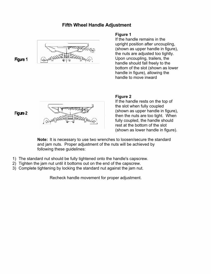
Fifth Wheel Handle Adjustment
Figure 1 If the handle remains in the upright position after uncoupling, (shown as upper handle in figure), the nuts are adjusted too tightly. Upon uncoupling, trailers, the handle should fall freely to the bottom of the slot (shown as lower handle in figure), allowing the handle to move inward Figure 2 If the handle rests on the top of the slot when fully coupled (shown as upper handle in figure), then the nuts are too tight. When fully coupled, the handle should rest at the bottom of the slot (shown as lower handle in figure).
Note: It is necessary to use two wrenches to loosen/secure the standard and jam nuts. Proper adjustment of the nuts will be achieved by following these guidelines:
1) The standard nut should be fully tightened onto the handle's capscrew. 2) Tighten the jam nut until it bottoms out on the end of the capscrew. 3) Complete tightening by locking the standard nut against the jam nut.
Recheck handle movement for proper adjustment.
Silver Eagle Fifth Wheel Maintenance
Silver Eagle Fifth Wheel Maintenance Jaw Removal (Item 12)
1. Make sure the jaw is closed. If not, it can be closed by pushing the trip block (9)
forward with a rod or bar. The jaw should be all the way across the center casting (the handle will be in). Caution: Keep your hands clear of the jaw, it is spring-loaded.
2. Using a pair of vise grips, clamp the trip lock rod in front of the guide hole on 5th wheel center casting (9) so as to prevent it from moving aft when jaw is removed.
3. When removing the guide bolt (19), applying an anti-seizing compound to the exposed threads often makes the removal process easier.
4. Remove the jaw spring (16) by pulling it through the push rod guide nut.
5. Pull the fifth wheel handle (18) all the way out such that the jaw (12) is fully retracted.
6. Disconnect the fifth wheel handle (18) from the lever (13) and the lever from the jaw/pushrod assy (9).
7. Remove the jaw/pushrod assy (12) from the 5th wheel table. 8. Lubricate and install the replacement jaw/pushrod assy (12) in the table making
sure the pointed tine on the jaw is to aft end of the dolly
9. Slide jaw/pushrod assy in place without spring. Align hole in jaw with mating hole in lever.
10. Apply loctite 242 medium strength thread adhesive or equivalent to cleaned threads of capscrew (17) and jam nut (11).
11. Thread capscrew (17) into jaw/pushrod assy (12) with two washers (14) between the capscrew head & the lever. Torque the jaw bolt to approximately 70 ft-lbs. The lever should have minimum clearance to allow free rotation against the jaw without binding through its full travel.
12. 13.
Tighten the jam nut (11) 1/6-1/4 turn – after contacting the jaw while ensuring the capscrew does not turn. Slide pushrod spring (16) on push rod of the jaw
14. While holding lever back far enough so the jaw pushrod protrudes into the guide nut, tighten the guide nut (19) securely
15. 16.
Remove the vise grips from the trip block rod (9) Test the table to ensure the jaw opens and closes properly, per drawing 86-033 A Fifth Wheel Handle Adjustment.
Jaw Spring Removal/ Reassembly (item 16)
Complete steps 1 through 4 of Jaw Removal.
Completes steps 13 through 17. Pull Handle Removal/ Reassembly (item 18)
Remove pull handle (18)
During Reassembly make sure the 2” jam nut (11) is jammed to the 2” standard nut (15) .
Test the table to ensure the jaw opens and closes properly.
Lever Removal/ Reassembly (item 13)
Complete step 1 & 6 of jaw removal
Install new lever (13)
Complete steps 10 thru 12 of jaw removal.
Test the table to ensure the jaw opens and closes properly per drawing 86-033 Rev B Fifth Wheel Handle Adjustment.
Trip block/ Trip block Spring Removal/ Reassembly
Complete steps 1 through 5
Remove the 3/8 bolt, 3/8 lock nut and the two 3/8 washers
Release the vise grips. Caution: The trip block is under spring
pressure Keep hands clear of it when releasing vise grips.
Remove the trip block (9) and the trip block spring (28) through the throat of the 5th wheel table. Caution: The jaw is under spring pressure. Use pliers or another suitable devise to remove old trip block and spring.
Install the new trip block and / or trip block spring in the throat of the
5th wheel table. Caution: The jaw is under spring pressure. Use pliers or another suitable devise to install new trip block and spring.
Push the trip block (9) as far forward as possible, with a rod or bar
and reinstall vise grips to the trip block rod of item (9) in front of 5th wheel center casting.
With anti-seize applied to the 3/8 bolt, reinstall the bolt, two washers
and lock nut making sure the trip block can freely move fore and aft when pushing on it with a rod or bar (leaving the lock nut 1/6”-3/32” from being fully tightened should work well).
Release the vise grips. Caution: The trip block is under spring pressure.
Keep hands clear of it when releasing vice grips.
Test the table to ensure the jaw opens and closes properly.
DRAWBAR EYE REMOVAL & INSTALLATION INSTRUCTIONS
1. Place dolly under a trailer. Set brakes on trailer and dolly. 2. Remove safety wire on 1283 nut. 3. Remove 1283 nut and 1193 washer. 4. Use forklift to hostler to pull against drawbar eye to remove it
from the shock housing. 5. Clean any debris from inside of shock absorber bushing
and lubricate. 6. Lubricate the shock absorber bushing with rubber lubricant
or soapy water and install into the shock housing. 7. Lubricate the shank of the new drawbar eye with rubber
lubricant or soapy water and install into the shock housing. NOTE: The shank of the drawbar eye will only be able to be pushed into the shock absorber bushings a little way by hand. There are two methods of pushing it in the final amount:
(1) Place the dolly under a trailer or up against a sold wall.
Set the brakes on the trailer and dolly. Use a forklift or hostler to push against the drawbar eye until it is seated on the shock absorber busing.
(2)Use a sledge hammer to hammer on the end of the drawbar eye until it is seated in the shock absorber bushing. 8. After the drawbar eye is in place, clean the threads on the shank.
Coat the threads with Never-SeeZ, pipe compound, or some other similar product.
9. Install the washer and thread the nut onto the shank. 10. Tighten the nut until the rubber shock absorber bushing bulge’s
toward the outer edge of the shock housing. NOTE: Shock absorber bushing may split if excessive tightening exists. By looking inside the threaded end of the shank, there should be two or three threads visible on the nut. 11. Install a safety wire on the nut to prevent it from backing off. 12. Periodically check on the tightness of the nut and adjust as necessary.
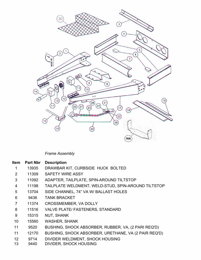
Frame Assembly
Item Part Nbr Description 1 13935 DRAWBAR KIT, CURBSIDE HUCK BOLTED 2 11309 SAFETY WIRE ASSY 3 11092 ADAPTER, TAILPLATE, SPIN-AROUND TILTSTOP 4 11198 TAILPLATE WELDMENT, WELD-STUD, SPIN-AROUND TILTSTOP 5 13704 SIDE CHANNEL, 74” VA W/ BALLAST HOLES 6 9436 TANK BRACKET 7 11374 CROSSMEMBER, VA DOLLY 8 11516 VALVE PLATE/ FASTENERS, STANDARD 9 15315 NUT, SHANK 10 15560 WASHER, SHANK 11 9520 BUSHING, SHOCK ABSORBER, RUBBER, VA, (2 PARI REQ'D) 11 12170 BUSHING, SHOCK ABSORBER, URETHANE, VA (2 PAIR REQ'D) 12 9714 DIVIDER WELDMENT, SHOCK HOUSING 13 9440 DIVIDER, SHOCK HOUSING
Item Part Nbr Description 14 1171 EYE & SHANK, ¼” SHANK, HRDN EYE 15 11011 SUPPORT LEG WELDMENT WITH FOOT 16 8808 RUBBER PAD, BOLT-ON, SUPPORT LEG 17 13936 DRAWBAR KIT, ROADSIDE HUCK BOLTED 18 11090 TILTSTOP, SPIN-AROUND
18A 13456 BALLAST HANGER W/FASTENERS 19 11151 BALLAST KIT, 20# 20 12710 SAFETY CHAIN ASSY, 1/2", RT U-BOLT, W/HOOK 21 1164 NUT, 5/8-11 UNC, METAL LOCK, HX, GR C, PLTD 22 7317 U-BOLT, KIT, RT, ZINC CHROMATE, SAFETY CHAIN 23 12570 CHAIN, 1/2", ZINC CHROMATE NS 7655 U-BOLT KIT, RT, SAFETY CHAIN 24 1172 WASHER, 5/8, FLAT, F436, HRND, PLTD 25 12021 HOOK, 5-TON, W/SAFETY LATCH 26 7318 PAINT PROTECTOR, SAFETY CHAIN 27 1183 LINK, LOCKING, 1/2, GR 8 28 5882 HANDLE ASSY, HINGED, UNDER DWB 30 10732 DRAWBAR BASKET/ FASTENERS NC 11711 FLAP HANGER SET, BETTS B67NT NC 7716 FLAP, 24 X 27 45 DEG, LH ANTI-SAIL BLK NC 7717 FLAP, 24 X 27 45 DEG, RH ANTI-SAIL BLK
All 100 units were included in campaign 01-TS2 14171 Tiltstop Campaign Kits Non-Hinged were installed on these units. 14171 Included Tiltstop Gussets - Roadside and Curbside.
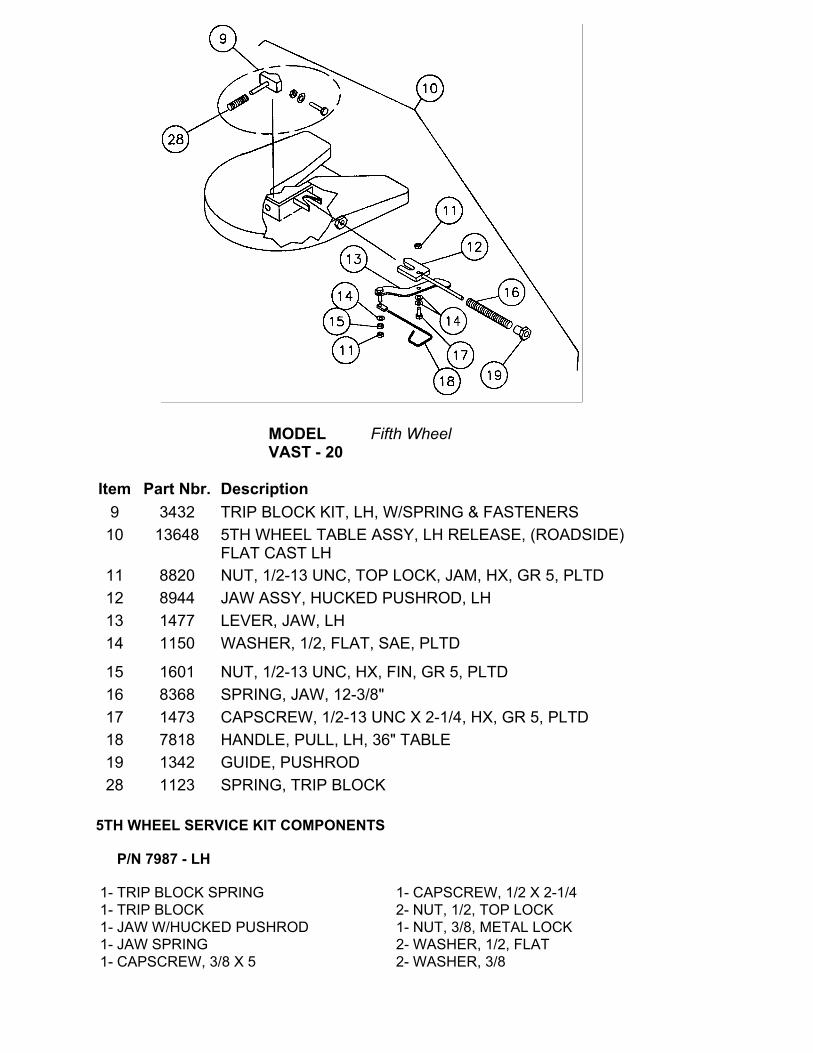
MODEL
VAST - 20 Fifth Wheel
Item Part Nbr. Description
9 3432 TRIP BLOCK KIT, LH, W/SPRING & FASTENERS 10 13648
5TH WHEEL TABLE ASSY, LH RELEASE, (ROADSIDE) FLAT CAST LH
11 8820 NUT, 1/2-13 UNC, TOP LOCK, JAM, HX, GR 5, PLTD 12 8944 JAW ASSY, HUCKED PUSHROD, LH 13 1477 LEVER, JAW, LH 14 1150 WASHER, 1/2, FLAT, SAE, PLTD
15 1601 NUT, 1/2-13 UNC, HX, FIN, GR 5, PLTD 16 8368 SPRING, JAW, 12-3/8" 17 1473 CAPSCREW, 1/2-13 UNC X 2-1/4, HX, GR 5, PLTD 18 7818 HANDLE, PULL, LH, 36" TABLE 19 1342 GUIDE, PUSHROD 28 1123 SPRING, TRIP BLOCK
5TH WHEEL SERVICE KIT COMPONENTS
P/N 7987 - LH
1- TRIP BLOCK SPRING 1- CAPSCREW, 1/2 X 2-1/4 1- TRIP BLOCK 2- NUT, 1/2, TOP LOCK 1- JAW W/HUCKED PUSHROD 1- NUT, 3/8, METAL LOCK 1- JAW SPRING 2- WASHER, 1/2, FLAT 1- CAPSCREW, 3/8 X 5 2- WASHER, 3/8
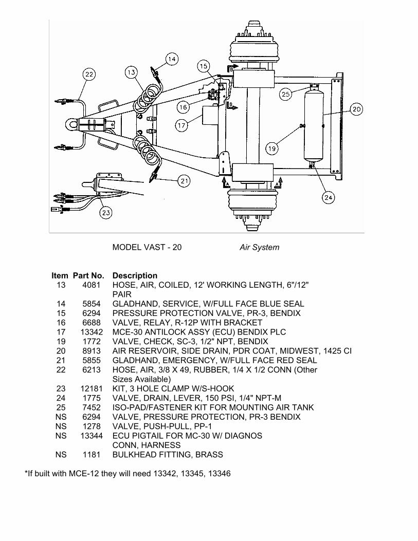
MODEL VAST - 20 Air System
Item
Part No.
Description
13 4081 HOSE, AIR, COILED, 12' WORKING LENGTH, 6"/12" PAIR
14 5854 GLADHAND, SERVICE, W/FULL FACE BLUE SEAL 15 6294 PRESSURE PROTECTION VALVE, PR-3, BENDIX 16 6688 VALVE, RELAY, R-12P WITH BRACKET 17 13342 MCE-30 ANTILOCK ASSY (ECU) BENDIX PLC 19 1772 VALVE, CHECK, SC-3, 1/2" NPT, BENDIX 20 8913 AIR RESERVOIR, SIDE DRAIN, PDR COAT, MIDWEST, 1425 CI 21 5855 GLADHAND, EMERGENCY, W/FULL FACE RED SEAL 22 6213 HOSE, AIR, 3/8 X 49, RUBBER, 1/4 X 1/2 CONN (Other
Sizes Available) 23 12181 KIT, 3 HOLE CLAMP W/S-HOOK 24 1775 VALVE, DRAIN, LEVER, 150 PSI, 1/4" NPT-M 25 7452 ISO-PAD/FASTENER KIT FOR MOUNTING AIR TANK NS 6294 VALVE, PRESSURE PROTECTION, PR-3 BENDIX NS 1278 VALVE, PUSH-PULL, PP-1 NS 13344 ECU PIGTAIL FOR MC-30 W/ DIAGNOS
CONN, HARNESS NS 1181 BULKHEAD FITTING, BRASS
*If built with MCE-12 they will need 13342, 13345, 13346
16
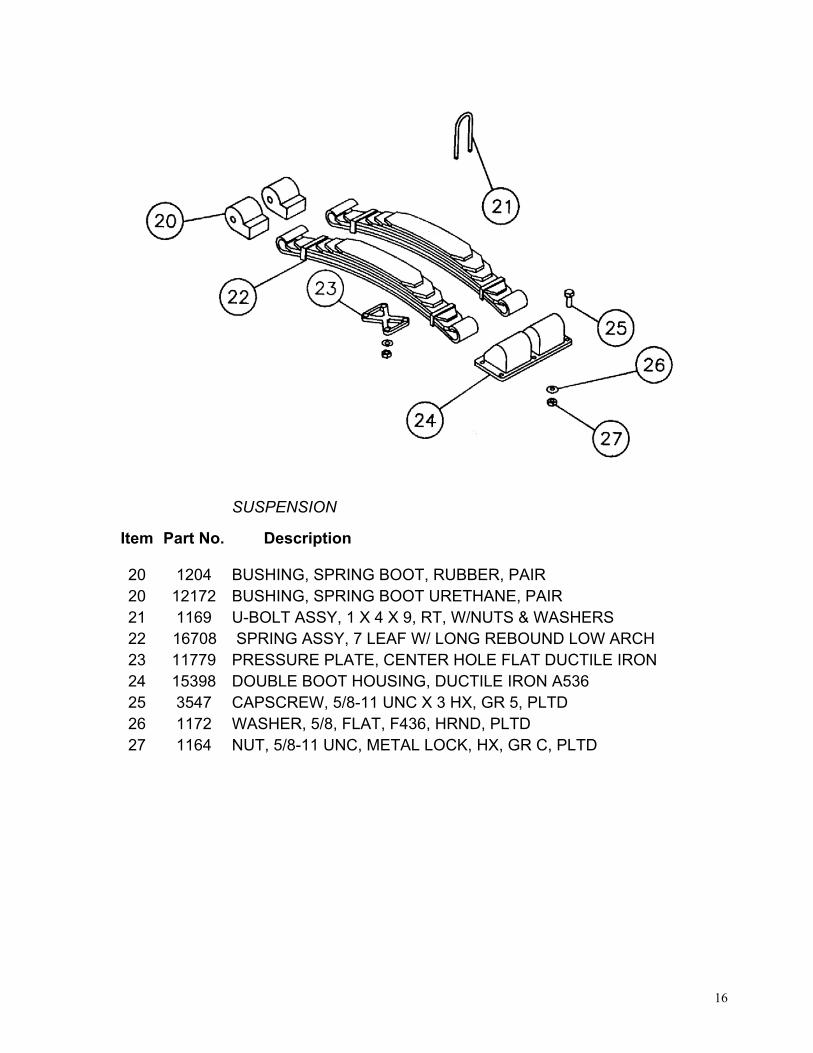
SUSPENSION
Item Part No. Description
20 1204 BUSHING, SPRING BOOT, RUBBER, PAIR 20 12172 BUSHING, SPRING BOOT URETHANE, PAIR 21 1169 U-BOLT ASSY, 1 X 4 X 9, RT, W/NUTS & WASHERS 22 16708 SPRING ASSY, 7 LEAF W/ LONG REBOUND LOW ARCH 23 11779 PRESSURE PLATE, CENTER HOLE FLAT DUCTILE IRON 24 15398 DOUBLE BOOT HOUSING, DUCTILE IRON A536 25 3547 CAPSCREW, 5/8-11 UNC X 3 HX, GR 5, PLTD 26 1172 WASHER, 5/8, FLAT, F436, HRND, PLTD 27 1164 NUT, 5/8-11 UNC, METAL LOCK, HX, GR C, PLTD
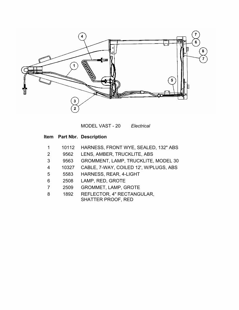
MODEL VAST - 20 Electrical
Item Part Nbr. Description
1 10112 HARNESS, FRONT WYE, SEALED, 132" ABS 2 9562 LENS, AMBER, TRUCKLITE, ABS 3 9563 GROMMENT, LAMP, TRUCKLITE, MODEL 30 4 10327 CABLE, 7-WAY, COILED 12', W/PLUGS, ABS 5 5583 HARNESS, REAR, 4-LIGHT 6 2508 LAMP, RED, GROTE 7 2509 GROMMET, LAMP, GROTE 8 1892 REFLECTOR, 4" RECTANGULAR,
SHATTER PROOF, RED