Embed Size (px)
Citation preview
FEM Barriers For Crash-Development:A New Modelling Approach
Bernhard Fellner (Magna Steyr), Bernd Fachbach (Mag na Steyr), Thomas Jost (vif), Thomas Heubrandtner (vif), Chris tian Ruff (vif)
Date: 30.08.2007 Author: Bernhard Fellner, R&D Crash & Safety 1
Abstract:Titel: FEM barriers for crash development – a new mo delling approachAuthor: Bernhard FellnerCo Authors: Thomas Jost, Thomas Heubrandtner, Christ ian Ruff, Bernd FachbachCompany: MAGNA STEYR Fahrzeugtechnik AG & Co KGKeywords: Design Optimisation / Safety
Abstract:Crash barriers with a defined stiffness and deforma tion behaviour are used to simulate the kinetic ene rgy and
energy absorption of a collision partner during an accident in vehicle safety development. Almost all actually used barriers are made of alumi nium honeycomb material in different layers and in different
stiffness. The deformation behaviour is made up by global and local effects like energy absorption, deformation and failure of the honeycomb, the glue and the covering blades. Behaviour strongly depends on the impacting structure and its surfaces.
A project of MAGNA STEYR together with our partners (VIF – The Virtual Vehicle Competence Centre / Dynamore / ESI) deals with the aim of an overall val idated numerical barrier model. High validation lab el on global and local deformation modes and effects as w ell as numerical stability and low computing costs are aimed. First focus has been laid on the IIHS side i mpact barrier. Benchmarks as well as several princi pal testing series have been carried out to analyse the regularity of global and local effects. Also many previously carried out full vehicle crashes from di fferent development projects have been analysed. Crashed barriers have been cut into sections to loo k at the local effects and their statistical behavi our. Various numerical studies have shown that the typic ally used solid elements are not any more accurate to local deformation behaviour. New modelling approach es have been tried, specifically a beam model shows significant improvement on reproduction of local de formation modes as well as global behaviour althoug h validation work is still going on.
When the work on the IIHS side impact barrier is fi nished the same modelling approach will be also used on the other barrier models used in safety dev elopment.
Date: 30.08.2007 Author: Bernhard Fellner, R&D Crash & Safety 2
Contents:
• Motivation:– Vehicle Development General – Conventional Barrier Performance
• Barrier Model Concepts:– Honeycomb Behaviour– Different Approaches for a Barrier Model – Testing / Validation
• Conclusion• Acknowledgements• References
Date: 30.08.2007 Author: Bernhard Fellner, R&D Crash & Safety 3
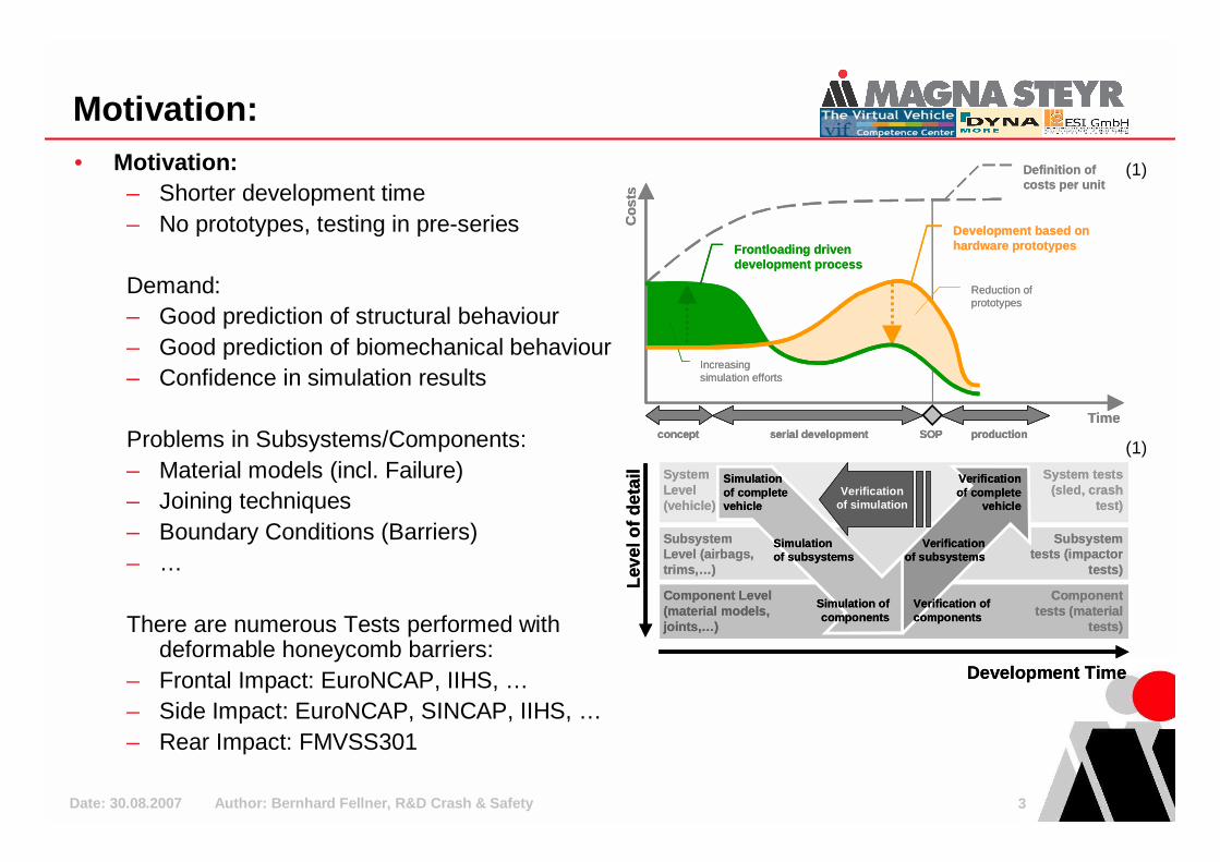
Motivation:• Motivation:
– Shorter development time– No prototypes, testing in pre-series
Demand:– Good prediction of structural behaviour– Good prediction of biomechanical behaviour– Confidence in simulation results
Problems in Subsystems/Components:– Material models (incl. Failure)– Joining techniques– Boundary Conditions (Barriers)– …
There are numerous Tests performed with deformable honeycomb barriers:
– Frontal Impact: EuroNCAP, IIHS, …– Side Impact: EuroNCAP, SINCAP, IIHS, …– Rear Impact: FMVSS301
productionconcept serial development SOP productionconcept serial development SOP productionconcept serial development SOP
Definition ofcosts per unitDefinition ofcosts per unit
Increasing simulation effortsIncreasing simulation efforts
Reduction ofprototypesReduction ofprototypes
Co
sts
Time
Co
sts
Time
Frontloading drivendevelopment processFrontloading drivendevelopment process
Development based on hardware prototypesDevelopment based on hardware prototypes
System Level (vehicle)
Subsystem Level (airbags, trims,…)
Component Level (material models, joints,…)
System Level (vehicle)
Subsystem Level (airbags, trims,…)
Component Level (material models, joints,…)
System tests (sled, crash
test)
Subsystem tests (impactor
tests)
Component tests (material
tests)
System tests (sled, crash
test)
Subsystem tests (impactor
tests)
Component tests (material
tests)
Verificationof simulationVerification
of simulation
Leve
l of d
etai
l
Development Time
Leve
l of d
etai
l
Development Time
Verificationof complete
vehicle
Verification of components
Verificationof subsystems
Verificationof complete
vehicle
Verification of components
Verificationof subsystems
Simulation of complete vehicle
Simulation of subsystems
Simulation ofcomponents
Simulation of complete vehicle
Simulation of subsystems
Simulation ofcomponents
(1)
(1)
Date: 30.08.2007 Author: Bernhard Fellner, R&D Crash & Safety 4
Motivation:
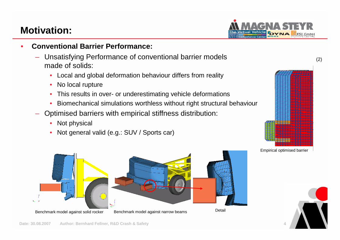
• Conventional Barrier Performance:– Unsatisfying Performance of conventional barrier models
made of solids:• Local and global deformation behaviour differs from reality• No local rupture
• This results in over- or underestimating vehicle deformations• Biomechanical simulations worthless without right structural behaviour
– Optimised barriers with empirical stiffness distribution:• Not physical• Not general valid (e.g.: SUV / Sports car)
Benchmark model against solid rocker Benchmark model against narrow beams Detail
(2)
Empirical optimised barrier

Date: 30.08.2007 Author: Bernhard Fellner, R&D Crash & Safety 5
Barrier Model Concepts:
• Deformation Analysis:– Honeycomb material shows typical deformation
modes:• Crushing in localized bands at a constant load level
in T-Direction
• Sliding of the deformed bands in LW-Plane• Folding bands in LW-Direction• Local rupture at a low force level
T-Direction:
LW-Direction:
(3)
(4)
Date: 30.08.2007 Author: Bernhard Fellner, R&D Crash & Safety 6
Barrier Model Concepts:
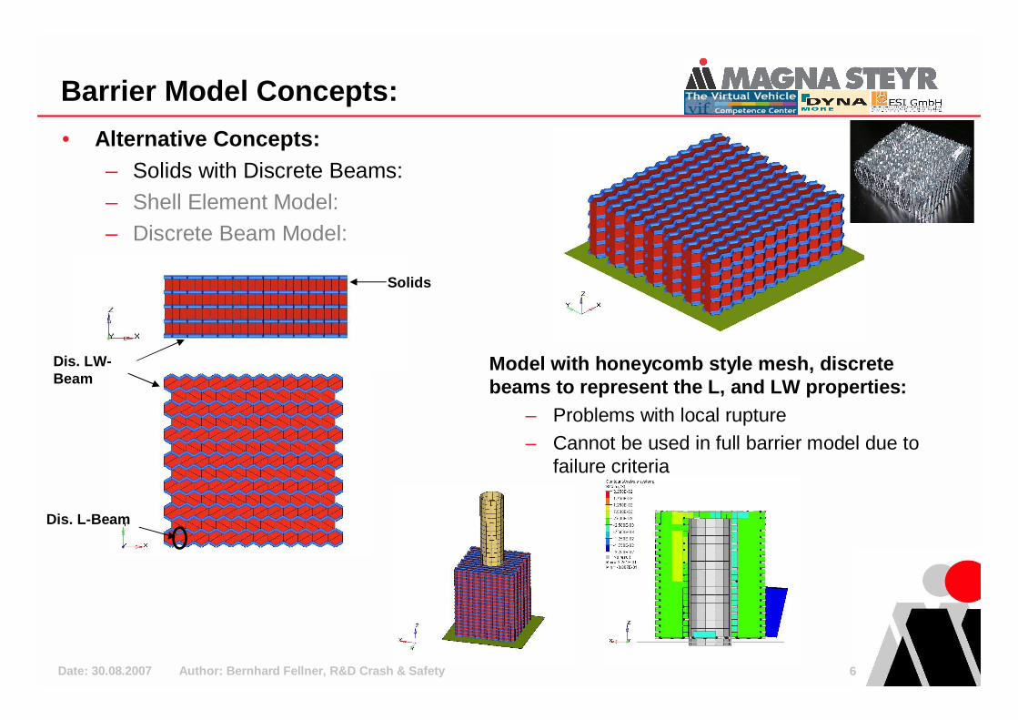
• Alternative Concepts:– Solids with Discrete Beams:– Shell Element Model:– Discrete Beam Model:
Dis. LW-Beam
Solids
Dis. L-Beam
Model with honeycomb style mesh, discrete beams to represent the L, and LW properties:
– Problems with local rupture– Cannot be used in full barrier model due to
failure criteria
Date: 30.08.2007 Author: Bernhard Fellner, R&D Crash & Safety 7
Barrier Model Concepts:
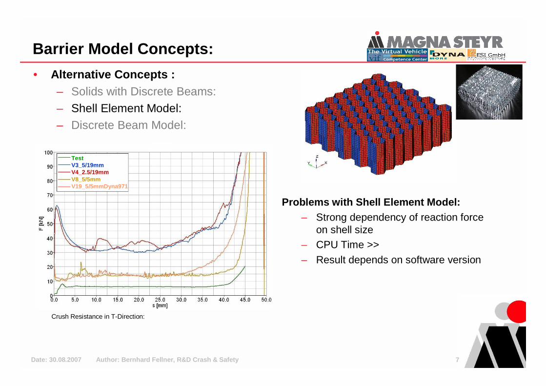
• Alternative Concepts :– Solids with Discrete Beams:– Shell Element Model:– Discrete Beam Model:
Problems with Shell Element Model:– Strong dependency of reaction force
on shell size– CPU Time >>
– Result depends on software version
Crush Resistance in T-Direction:
TestV3_5/19mmV4_2.5/19mmV8_5/5mmV19_5/5mmDyna971
TestV3_5/19mmV4_2.5/19mmV8_5/5mmV19_5/5mmDyna971
Date: 30.08.2007 Author: Bernhard Fellner, R&D Crash & Safety 8
Barrier Model Concepts:
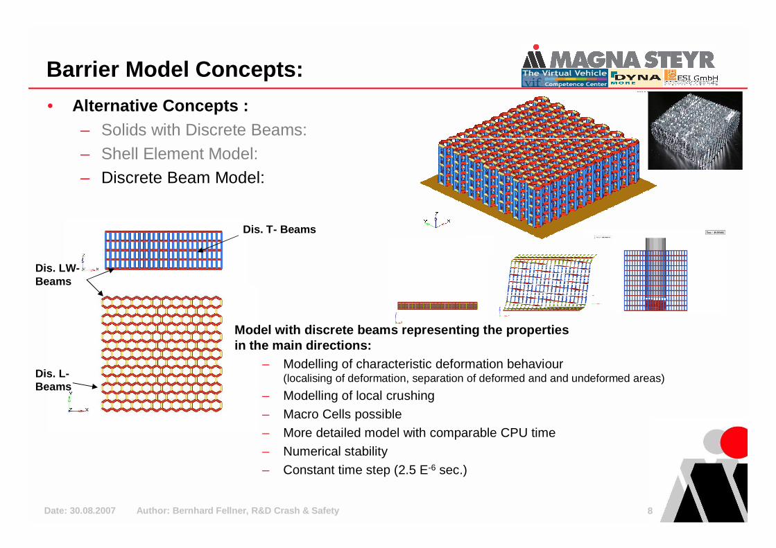
• Alternative Concepts :– Solids with Discrete Beams:– Shell Element Model:– Discrete Beam Model:
Dis. T- Beams
Dis. LW-Beams
Dis. L-Beams
Model with discrete beams representing the properti es in the main directions:
– Modelling of characteristic deformation behaviour(localising of deformation, separation of deformed and and undeformed areas)
– Modelling of local crushing
– Macro Cells possible
– More detailed model with comparable CPU time
– Numerical stability
– Constant time step (2.5 E-6 sec.)
Date: 30.08.2007 Author: Bernhard Fellner, R&D Crash & Safety 9
Barrier Model Concepts:
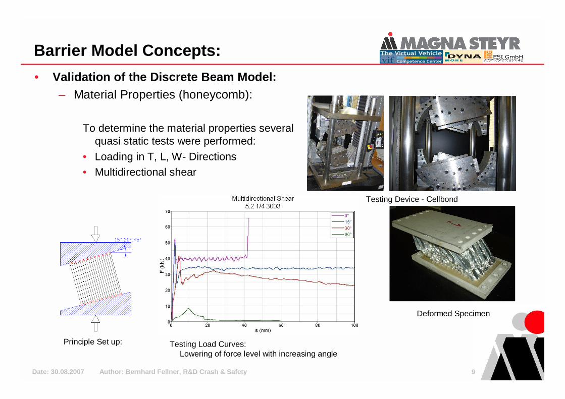
• Validation of the Discrete Beam Model:– Material Properties (honeycomb):
To determine the material properties several quasi static tests were performed:
• Loading in T, L, W- Directions• Multidirectional shear
Testing Device - Cellbond
Principle Set up: Testing Load Curves:Lowering of force level with increasing angle
Deformed Specimen
Date: 30.08.2007 Author: Bernhard Fellner, R&D Crash & Safety 10
Barrier Model Concepts:
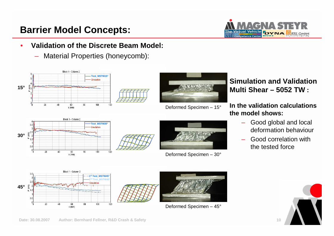
• Validation of the Discrete Beam Model:– Material Properties (honeycomb):
15°
30°
45°
Deformed Specimen – 15°
Deformed Specimen – 30°
Deformed Specimen – 45°
Simulation and Validation Multi Shear – 5052 TW :
In the validation calculations the model shows:
– Good global and local deformation behaviour
– Good correlation with the tested force
Test_MSTW15°
Test_MSTW30°
1st Test_MSTW45°2nd Test_MSTW45°

Date: 30.08.2007 Author: Bernhard Fellner, R&D Crash & Safety 11
Barrier Model Concepts:
• Validation of the Discrete Beam Model:– Component Testing (honeycomb, glue and cladding):
Test Setup Main Block Specimen Bumper Specimen
For the next step in validation, specimens with cladding were cut out of the bumper and the main block:
– Impact with different punch forms (spherical, cylindrical, rectangular)
Output:– Force levels for honeycomb deformation– Glue failure– Cladding deformation / rupture
Date: 30.08.2007 Author: Bernhard Fellner, R&D Crash & Safety 12
Barrier Model Concepts:
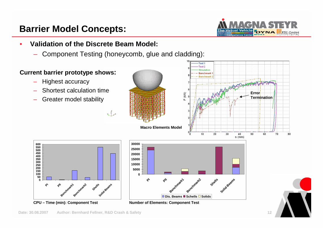
• Validation of the Discrete Beam Model:– Component Testing (honeycomb, glue and cladding):
Current barrier prototype shows :– Highest accuracy
– Shortest calculation time– Greater model stability
Number of Elements: Component TestCPU – Time (min): Component Test
050
100150200250300350400450500550600
PI
PIIBen
chm
ark1
Benchm
ark2
Shells
Solid-B
eam
s
0
5000
10000
15000
20000
25000
30000
PI
PIIBen
chm
ark1
Bench
mark2
Shells
Solid-
Beams
Dis. Beams Schells Solids
Macro Elements Model
Error Termination
Date: 30.08.2007 Author: Bernhard Fellner, R&D Crash & Safety 13
Barrier Model Concepts:
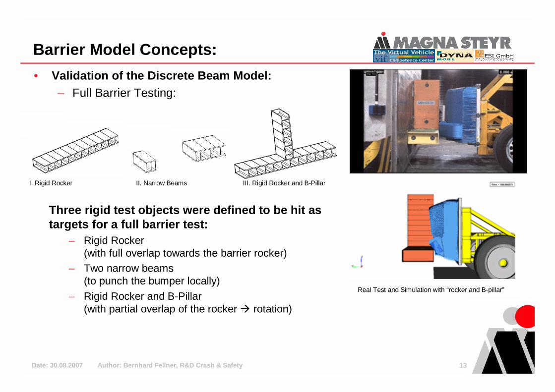
• Validation of the Discrete Beam Model:– Full Barrier Testing:
Three rigid test objects were defined to be hit as targets for a full barrier test:
– Rigid Rocker (with full overlap towards the barrier rocker)
– Two narrow beams (to punch the bumper locally)
– Rigid Rocker and B-Pillar (with partial overlap of the rocker � rotation)
I. Rigid Rocker II. Narrow Beams III. Rigid Rocker and B-Pillar
Real Test and Simulation with “rocker and B-pillar”
Date: 30.08.2007 Author: Bernhard Fellner, R&D Crash & Safety 14
Barrier Model Concepts:
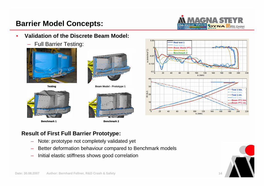
• Validation of the Discrete Beam Model:– Full Barrier Testing:
Benchmark 1Benchmark 1 Benchmark 2Benchmark 2
Beam Model - Prototype 1TestingTesting
Result of First Full Barrier Prototype:– Note: prototype not completely validated yet– Better deformation behaviour compared to Benchmark models– Initial elastic stiffness shows good correlation
Real test 1Real test 2Beam Model PT1Benchmark 1Benchmark 2
Test 1 kin.Test 2 kin.Test 1 int.Test 2 int.Beam PT1 kin.Beam PT1 int.
Date: 30.08.2007 Author: Bernhard Fellner, R&D Crash & Safety 15
Barrier Model Concepts:
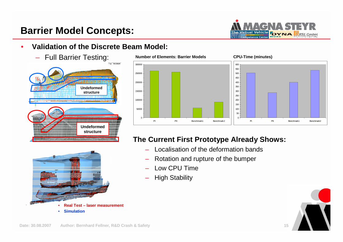
• Validation of the Discrete Beam Model:– Full Barrier Testing:
Undeformedstructure
Undeformedstructure
• Real Test – laser measurement• Simulation
Number of Elements: Barrier Models
0
50000
100000
150000
200000
250000
300000
PI PII Benchmark1 Benchmark20
50
100
150
200
250
300
350
400
450
500
550
600
PI PII Benchmark1 Benchmark2
CPU-Time (minutes)
The Current First Prototype Already Shows:– Localisation of the deformation bands– Rotation and rupture of the bumper– Low CPU Time
– High Stability

Date: 30.08.2007 Author: Bernhard Fellner, R&D Crash & Safety 16
Conclusion:
This new modelling method presented shows:– Simulated deformation modes are as seen in the
tests– Principle tests have been validated
� barrier is based on physical properties– No non physical tuning out of experience
required– Low CPU time at a higher resolution– Constant time step– Good correlation in subsystem and full barrier
tests – Method is valid for any honeycomb material
(e.g. ODB-front)
Date: 30.08.2007 Author: Bernhard Fellner, R&D Crash & Safety 17
Conclusion:
• Next Steps / Current Projects:– Build up of fully validated IIHS Barrier– ODB Front Barrier development– Further projects on spotweld(5) and material failure;
riveting, gluing, fuel system failure…
• Contact:Bernhard FellnerR&D Crash & Safety, Magna Steyr Graz
+43 676 8240 [email protected]
Date: 30.08.2007 Author: Bernhard Fellner, R&D Crash & Safety 18
References:
• Journals/Magazines:(3) Tomasz Wierzbicki, “Crushing Analysis of Metal Honeycombs.”, Int. J. Impact Engineering, Vol. 1, No. 2 (1983), P. 157-174(4) Qing Zhou, Robert R. Mayer, “Characterization of Aluminium Honeycomb Material Failure in Large Deformation Compression,
Shear, and Tearing.”, Journal of Engineering Materials and Technology, Vol. 124 (October 2002), P. 412-420
• Thesis(2) Andreas Klotz, “Untersuchung von empirischen Ansätzen zur FEM-Modellierung von Crash Barrieren”, FH Joanneum, Graz,
2007
• Conference Papers:(1) Arno Eichberger, “A NOVEL VIRTUAL DEVELOPMENT PROCESS FOR SIDE IMPACT AT MAGNA STEYR BASED ON
NUMERICAL SIMULATIONS VERIFIED BY COMPONENT TESTING”, EUROSIM, 2007
(5) Thomas Heubrandtner, “Advanced Spot Welds for Crash Simulations“, European HTC, 2007