Embed Size (px)
Citation preview


Attachment 5
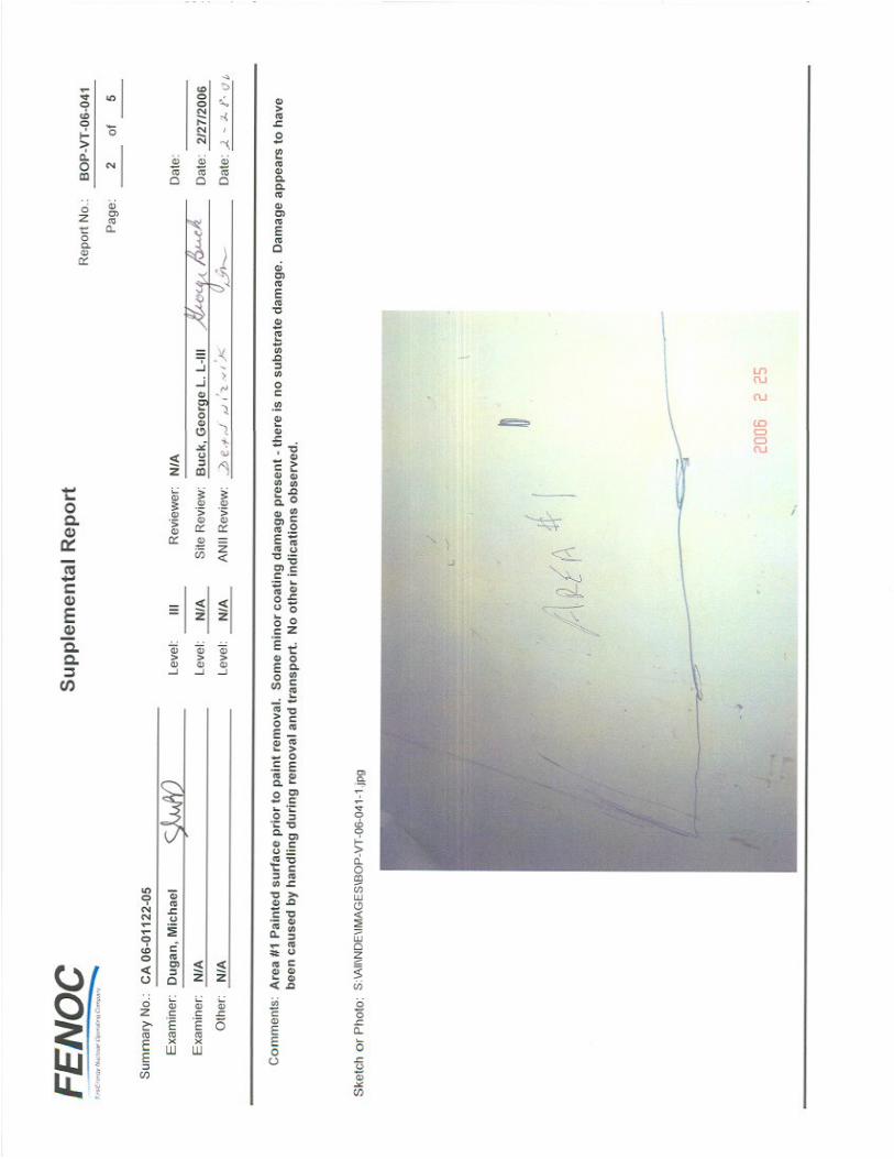
NDE VT Reports
(7 pages)


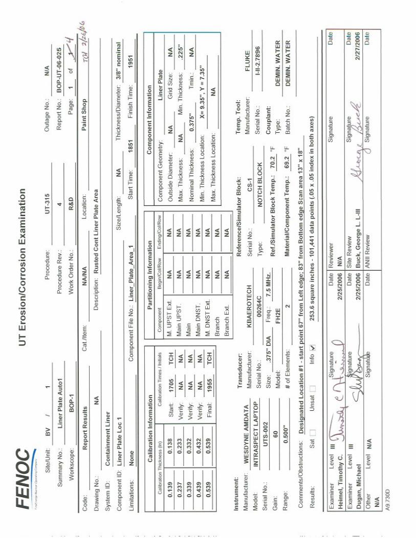
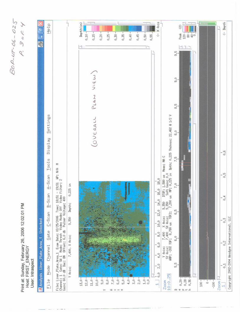
Attachment 6
NDE UT Reports
(19 pages)


Attachment 7
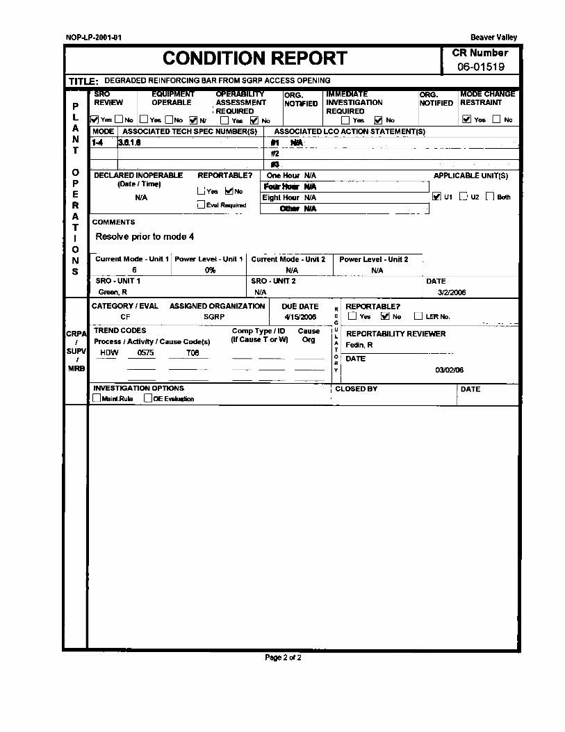
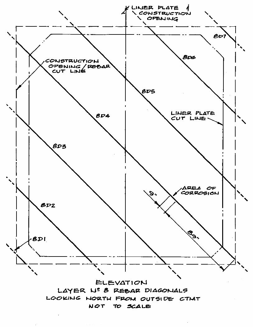
CR 06-01519 – Degraded Reinforcing Bar from SGRP Access Opening
(6 pages)


Attachment 8
Beta Labs Report M06074
(78 pages)

BETA LaboratoryISO 9001 Registered
METALLURGICAL LABORATORY
LAB NO.: M06074 WORK TRACKING NO.: 14878 PAGE 1 OF 78PLANT & UNIT: BEAVER VALLEY #1 PART: CONTAINMENT MATERIALS DATE: 3/9/2006
MATERIAL ANALYSIS REPORT
6670 Beta Dr., Mayfield Village, OH 44143, Tel: (440) 604-9843, Fax: (440) 604-9800, e-mail: [email protected]
CONTACT: D. WEAKLAND
ISSUED BY: D. KLESCH
TELEPHONE EXTENSION: 8824/ 9864 MAIL STOP: A-BETA
REVIEWED BY (SIGNATURE ON FILE): J. BLOUGH
REPORT ISSUED TO:B. SIKORSKI D. WEAKLAND
SAMPLE DESCRIPTION: Two (2) sample pieces of steel removed from the containment shell liner and assorted sample pieces of the associated concrete shell from Beaver Valley #1 Unit were forwarded for evaluation of external (OD, concrete side) corrosion distress of the steel liner seen visually during disassembly work in the 1R17 Outage, see Figures 1-3.
The steel liner sample pieces had been pre-labeled “A” and “B” and were marked with a grid pattern, as-received, designations that were retained strictly for tracking purposes in the Lab. The concrete samples, seen in Figure 4, were labeled #1 (“Large”) and #2 (“Small”). The #1 sample (bag label only partly legible) was identified from “against the liner”; the #2 sample was from ~12” outside of the inner rebar layer.
NOTE: Plant personnel later confirmed that the steel liner sample marked “A” corresponds to Area 1; the sample marked “B” to the Area 2, in the Plant images provided.
SUMMARY: External “rust” corrosion of undetermined activity or vintage is confirmed on the steel liner. The “rust” corrosion is attributed to oxidation of the plain or mild steel, where oxygen and water would be required simultaneously; chlorides (Cl) could aggravate the corrosion if also present at the same time.
ATTRIBUTE #SAMPLES DESCRIPTION TOTAL FOUND
LINER OD SURFACE COLD-WORK 15 3 TRACES SEEN IN “B” Q10-#1 AND “B” Q10-#4 AND WELD AREA
LINER OD SURFACE PITS 15 5 SOME WITH UNDERCUT AND END-GRAIN IN WORST AREAS
LINER OD CORROSION PRODUCT 15 15 “DEPOSIT/ SCALE” RESIDUES REMAINED ON ALL SAMPLES EXAMINED
LINER ID SURFACE PITS 15 0 NONE IDENTIFIED AS SUCH
LINER ID SURFACE COLD-WORK 15 15 ABUNDANT, ATTRIBUTED TO SURFACE CLEANING PROCESSES
LINER MICROSTRUCTURE 15 15 FERRITE-PEARLITE AND STRINGERS, AS-ROLLED
LINER CORROSION PRODUCTS IN-SITU 7 NA UP TO 2.3% CA, 1.8% SI, 0.7% S; CL NOT DETECTED
LINER COMPOSITION 3 NA NOMINALLY 0.19% C, 0.76% MN, SI KILLED STEEL
LINER HARDNESS 3 NA RANGE 71.3-76.5 HRBLINER TYPICAL WALL THICKNESS 15 NA ~3/8” (0.375”) NOMINAL; ~25/64” (0.390”) MAXIMUM MEASURED
LINER MINIMUM WALL THICKNESS 15 NA ~5/32” (0.156”) LOCATED AT A PIT IN “B” Q10-#5
STUD WELD 1 1 FULL CONTACT FUSION
LINER WELD 1 1 CLEAN AND SOUND, MULTI-PASS FROM BOTH SIDES
SEM-EDS ANALYSIS
AS-RECEIVED WASHED IN DE-IONIZED WATER
BULK LINER OD SURFACE, CALCIUM 3 3 UP TO 26.4% UP TO 5.9% IN BROWN SURFACE
BULK LINER OD SURFACE, SILICON 3 3 UP TO 3.7% UP TO 1.4% IN BROWN SURFACE
BULK LINER OD SURFACE, SULFUR 3 3 UP TO 2.9% 0.2 % IN BROWN SURFACE
BULK LINER OD SURFACE, CHLORINE 3 2 UP TO 0.3% NOT DETECTED
CONCRETE CALCIUM 3 3 20.2-38.5% CONCRETE SILICON 3 3 13.6-33.8% CONCRETE SULFUR 3 3 0.3-0.4% CONCRETE NEXT TO LINER, 3 1 0.1% FOUND BY EDS, PH 10.62, CL NOT DETECTED BY ICCONCRETE AWAY FROM LINER 1 1 10.67 PH, 0.56 PPM CL BY ION CHROMATOGRAPHY (IC)

BETA LaboratoryISO 9001 Registered
METALLURGICAL LABORATORY
LAB NO.: M06074 WORK TRACKING NO.: 14878 PAGE 2 OF 78PLANT & UNIT: BEAVER VALLEY #1 PART: CONTAINMENT MATERIALS DATE: 3/9/2006
MATERIAL ANALYSIS REPORT
6670 Beta Dr., Mayfield Village, OH 44143, Tel: (440) 604-9843, Fax: (440) 604-9800, e-mail: [email protected]
BACKGROUND: Plant personnel reported that the liner distress was seen when the liner plate was exposed by the removal of the concrete containment building shell to facilitate 1R17 Outage Work. Site Engineering identified the containment liner as a steel vapor barrier attached by “Nelson-Studs” to the reinforced concrete shell. The concrete was removed by high-pressure water-blasting. Filtered river water was used for the “hydro-demolition.” No test results for chlorides on the water used during this work were reported, and chloride content of river water is not normally measured at the Plant. A filtered river water sample was taken by Plant personnel approximately two weeks after the hydro-demolition for analysis. The reported results were: 1) pH-7.54, 2), Chloride 50 ppm, and 3) Sulfate 68 ppm.
Plant personnel provided the following data concerning the liner plate and weld materials from material test reports in the BVPS site fabrication records. The liner plate material was ASTM A516 Grade 60 steel. The liner manufacturer’s drawing identifies the welding procedures used to make the welds in the liner. Vertical welds were done with the shielded metal arc (SMAW) welding process with E-7018 electrodes.”
TESTS PERFORMED: Visual examinations, chemical analysis via vacuum spectrometry, standardless SEM-EDS, hardness, microstructures, and pH and ion chromatography in the Beta Water Lab.
TEST RESULTS: Concrete, visual examinations found the heterogeneous sample pieces seen in Figures 5 and 6. The smaller sample was more irregular, reportedly having been recovered from ~12” from the inner rebar layer. The larger sample was removed by site engineering personnel. One surface of this piece was identified by Plant personnel as being in contact with the OD of the steel liner plate, and the opposite end was in contact with the first layer of reinforcing bar. The “flat” surface of this larger piece, reported to have been against the liner at the time of removal, was relatively smooth, except for spherical appearing voids. The estimated void size was approximately 1/16”-1/8” Ø, see Figure 7.
It should be noted that, reportedly, the larger concrete sample had to be foam-cleaned to allow its release from the Plant. Site personnel contacted the manufacturer of the “Syntech Touch-it-up Aerosol,” the cleaning agent used, regarding the chemical contents of the product. The manufacturer provided a typical analysis that reported a “Total Halogens 38 ppm, as Cl” and “Total Sulfur 2 ppm. The MSDS form for the cleaner listed its chemical constituents as 2 butoxy ethanol; sodium metasilicate; octylphenol polyethoxylate; trisodium phosphate, and hydrocarbon propellant.)
Studs, visual examinations found “headed-studs”, approximately 5/8”Ø X 6¼” long, had been stud-welded to the external (OD) surfaces of the containment liner; all appeared to be in good condition. One stud (1) had been removed from the sample “B” section prior to receipt at Beta. Other stud-welded pieces of round steel bar-stock, approximately 3/8”Ø X 12” long, were noted.
Steel Liner, sample grid patterns that were marked in white (as-received) on the OD were numbered as Quadrants (“Q”); #1-12 for sample “A” and #1-16 for sample “B”, strictly for tracking purposes in the Lab. Visual examinations, see Figures 8 and 9, found that the external (OD, toward the concrete) surface conditions varied from locally rough and irregular with obvious pits to smooth and apparently unaffected.
The sample “B” section also contained a vertical weld joining two (2) sections of the liner; the corrosion of the external surfaces extended across (and included) this weld. Chemical analysis of a sample piece of each steel liner section, one (1) from “A” and two (2) from two (2) from “B” (one on each side of the weld), found similar compositions, nominally 0.19% C, 0.76% Mn and 0.26% Si, see Table 2 for all of the results.
Hardness tests of sample pieces from each of the three (3) steel liner sections included found similar values in the range of 71.3-76.5 HRB, see Table 3 for comparisons. Sample “A” was sectioned to extract selected areas (Quadrant #11) for additional study, see Figures 10 and 11. Sample “B” was sectioned to extract selected areas (mainly Quadrant #10) for additional study, see Figures 12 and 13.
BETA LaboratoryISO 9001 Registered
METALLURGICAL LABORATORY
LAB NO.: M06074 WORK TRACKING NO.: 14878 PAGE 3 OF 78PLANT & UNIT: BEAVER VALLEY #1 PART: CONTAINMENT MATERIALS DATE: 3/9/2006
MATERIAL ANALYSIS REPORT
6670 Beta Dr., Mayfield Village, OH 44143, Tel: (440) 604-9843, Fax: (440) 604-9800, e-mail: [email protected]
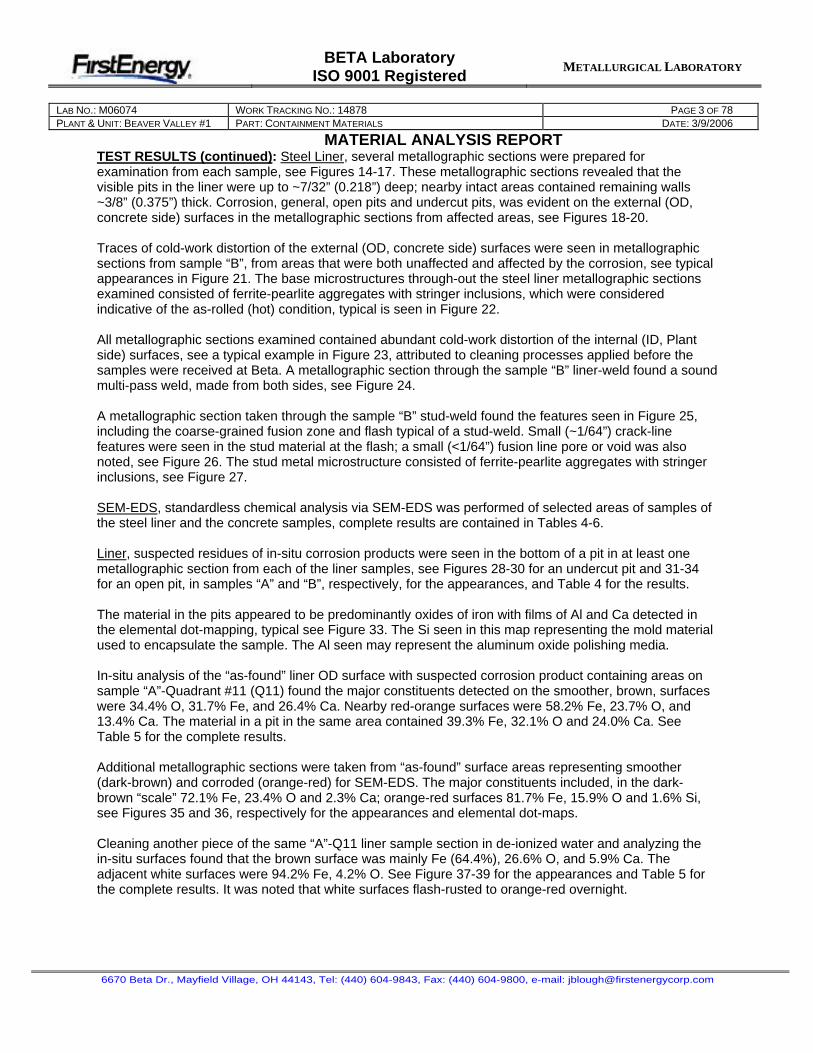
TEST RESULTS (continued): Steel Liner, several metallographic sections were prepared for examination from each sample, see Figures 14-17. These metallographic sections revealed that the visible pits in the liner were up to ~7/32” (0.218”) deep; nearby intact areas contained remaining walls ~3/8” (0.375”) thick. Corrosion, general, open pits and undercut pits, was evident on the external (OD, concrete side) surfaces in the metallographic sections from affected areas, see Figures 18-20.
Traces of cold-work distortion of the external (OD, concrete side) surfaces were seen in metallographic sections from sample “B”, from areas that were both unaffected and affected by the corrosion, see typical appearances in Figure 21. The base microstructures through-out the steel liner metallographic sections examined consisted of ferrite-pearlite aggregates with stringer inclusions, which were considered indicative of the as-rolled (hot) condition, typical is seen in Figure 22.
All metallographic sections examined contained abundant cold-work distortion of the internal (ID, Plant side) surfaces, see a typical example in Figure 23, attributed to cleaning processes applied before the samples were received at Beta. A metallographic section through the sample “B” liner-weld found a sound multi-pass weld, made from both sides, see Figure 24.
A metallographic section taken through the sample “B” stud-weld found the features seen in Figure 25, including the coarse-grained fusion zone and flash typical of a stud-weld. Small (~1/64”) crack-line features were seen in the stud material at the flash; a small (<1/64”) fusion line pore or void was also noted, see Figure 26. The stud metal microstructure consisted of ferrite-pearlite aggregates with stringer inclusions, see Figure 27.
SEM-EDS, standardless chemical analysis via SEM-EDS was performed of selected areas of samples of the steel liner and the concrete samples, complete results are contained in Tables 4-6.
Liner, suspected residues of in-situ corrosion products were seen in the bottom of a pit in at least one metallographic section from each of the liner samples, see Figures 28-30 for an undercut pit and 31-34 for an open pit, in samples “A” and “B”, respectively, for the appearances, and Table 4 for the results.
The material in the pits appeared to be predominantly oxides of iron with films of Al and Ca detected in the elemental dot-mapping, typical see Figure 33. The Si seen in this map representing the mold material used to encapsulate the sample. The Al seen may represent the aluminum oxide polishing media.
In-situ analysis of the “as-found” liner OD surface with suspected corrosion product containing areas on sample “A”-Quadrant #11 (Q11) found the major constituents detected on the smoother, brown, surfaces were 34.4% O, 31.7% Fe, and 26.4% Ca. Nearby red-orange surfaces were 58.2% Fe, 23.7% O, and 13.4% Ca. The material in a pit in the same area contained 39.3% Fe, 32.1% O and 24.0% Ca. See Table 5 for the complete results.
Additional metallographic sections were taken from “as-found” surface areas representing smoother (dark-brown) and corroded (orange-red) for SEM-EDS. The major constituents included, in the dark-brown “scale” 72.1% Fe, 23.4% O and 2.3% Ca; orange-red surfaces 81.7% Fe, 15.9% O and 1.6% Si, see Figures 35 and 36, respectively for the appearances and elemental dot-maps.
Cleaning another piece of the same “A”-Q11 liner sample section in de-ionized water and analyzing the in-situ surfaces found that the brown surface was mainly Fe (64.4%), 26.6% O, and 5.9% Ca. The adjacent white surfaces were 94.2% Fe, 4.2% O. See Figure 37-39 for the appearances and Table 5 for the complete results. It was noted that white surfaces flash-rusted to orange-red overnight.

BETA LaboratoryISO 9001 Registered
METALLURGICAL LABORATORY
LAB NO.: M06074 WORK TRACKING NO.: 14878 PAGE 4 OF 78PLANT & UNIT: BEAVER VALLEY #1 PART: CONTAINMENT MATERIALS DATE: 3/9/2006
MATERIAL ANALYSIS REPORT
6670 Beta Dr., Mayfield Village, OH 44143, Tel: (440) 604-9843, Fax: (440) 604-9800, e-mail: [email protected]
TEST RESULTS (continued): Concrete, the results of chemical analysis of selected surfaces via standardless SEM-EDS of the concrete sample pieces are seen in Figures 40-47; although various species were identified, Cl was not detected in any of the elemental dot-mapping, see Figures 41 and 42 for the #1 (“Large Piece”) sample examined and Figures 45 and 47 for the #2 (“Small Piece”). “Spot” analyses found 0.1% Cl in the #1 “flat” (“special”) sample that had reportedly been foam-cleaned with “Syntech Touch-it-up Aerosol” at the Plant to allow its release, among the compositions listed in Table 6.
Beta Water-Lab, samples from (large piece #1 and small piece #2) pieces of the concrete were crushed, sieved and leached with de-ionized water for pH and ion chromatography analysis, see Attachment #2 for the Beta Water Lab Report, the pH was 10.63-10.67; the % water soluble was 2.58-2.59% and the chloride content was none detected in the “large piece #1 flat surface” and 0.56 ppm in “small piece #2”.
CONCLUSIONS: External (OD, concrete side) “rust” corrosion of the steel liner, occurring via general wastage and pitting, was confirmed in the localized areas seen visually. The pits were up to ~7/32” deep, leaving a minimum wall of ~5/32” in the deepest pit studied. The nominal wall was approximately 3/8” thick; the thickest remaining wall measured was an estimated 25/64” (0.390”).
It was apparent that the liner corrosion in Area 2 must have occurred after the weld was made, since the visible pattern of surface distress continued from one side to the other and included the weld itself. No preferential corrosion of the weld or the heat-affected zones (HAZ) was identified.
The liner samples appeared to represent a mild or plain carbon-manganese (C-Mn), silicon (Si) killed (de-oxidized) steel “as-rolled”, closely resembling A516-90, Grade 60; since this was almost certainly rolled hot, the surface cold-work distortion seen is probably not from original plate manufacture. The weld in sample “B” (Area 2) had been made with multiple passes from both sides; the weld metal was clean an sound in the section examined. It appears that lower carbon, higher manganese and silicon filler metals, such as E7018, had been used in this welding.
The stud-weld sample section examined contained the flash and heat affected zones considered typical for the process. Small (<1/64”) crack-like indications were seen in the stud sample near the flash. One small (<1/64”) pore or void was seen at or near the fusion line.
The Water Lab concrete analyses found trace amounts of water-soluble chlorides, 0.56 parts per million (ppm), in the small piece (#2) away from the liner, the water extracted “leachate” tested had a pH 10.63-10.67, see Attachment #2 for the particular details of this work.
All of the surviving sample remains will be retained for a minimum of ninety days (90 days) for possible review or consultation, after which they will be discarded, unless otherwise requested.
DISCUSSION: Although it can be said with certainty that the simultaneous presence of oxygen and water are required for the “rusting” of steel, producing hydrated oxides, the exact cause of this condition in this instance, its vintage or current state of activity, could not be determined with any certainty at this time by metallurgical analysis alone. Chlorides could aggravate the corrosion if also present at the same time.
Attempts to characterize the surface oxides seen in areas that appeared relatively unaffected, either semi-quantitatively via SEM-EDS or morphologically, as either “rust”, representing corrosion products, or mill-scale, appear inconclusive at this time. By definition, mill-scale*, is the “heavy oxide layer formed during hot fabrication or heat treatment of metals.” Since the original surface conditions of the liner, or how mill-scale might behave in the in-situ environment over time, are not known, further evaluation here is precluded by the complexity, lack of data, and time constraints.
* American Society for Metals, “Glossary of Metallurgical Terms and Engineering Tables.” ©1979, p. 48.
BETA LaboratoryISO 9001 Registered
METALLURGICAL LABORATORY
LAB NO.: M06074 WORK TRACKING NO.: 14878 PAGE 5 OF 78PLANT & UNIT: BEAVER VALLEY #1 PART: CONTAINMENT MATERIALS DATE: 3/9/2006
MATERIAL ANALYSIS REPORT
6670 Beta Dr., Mayfield Village, OH 44143, Tel: (440) 604-9843, Fax: (440) 604-9800, e-mail: [email protected]
TABLE OF CONTENTS
ITEM PAGE DESCRIPTION
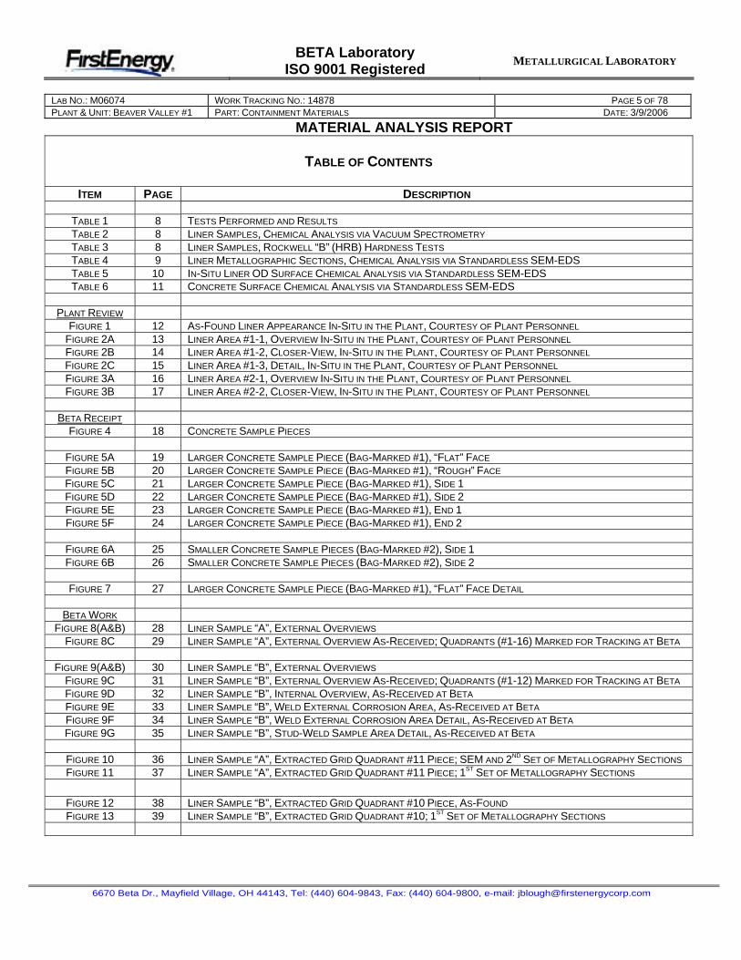
TABLE 1 8 TESTS PERFORMED AND RESULTS
TABLE 2 8 LINER SAMPLES, CHEMICAL ANALYSIS VIA VACUUM SPECTROMETRY
TABLE 3 8 LINER SAMPLES, ROCKWELL “B” (HRB) HARDNESS TESTS
TABLE 4 9 LINER METALLOGRAPHIC SECTIONS, CHEMICAL ANALYSIS VIA STANDARDLESS SEM-EDSTABLE 5 10 IN-SITU LINER OD SURFACE CHEMICAL ANALYSIS VIA STANDARDLESS SEM-EDS TABLE 6 11 CONCRETE SURFACE CHEMICAL ANALYSIS VIA STANDARDLESS SEM-EDS
PLANT REVIEW
FIGURE 1 12 AS-FOUND LINER APPEARANCE IN-SITU IN THE PLANT, COURTESY OF PLANT PERSONNEL
FIGURE 2A 13 LINER AREA #1-1, OVERVIEW IN-SITU IN THE PLANT, COURTESY OF PLANT PERSONNEL
FIGURE 2B 14 LINER AREA #1-2, CLOSER-VIEW, IN-SITU IN THE PLANT, COURTESY OF PLANT PERSONNEL
FIGURE 2C 15 LINER AREA #1-3, DETAIL, IN-SITU IN THE PLANT, COURTESY OF PLANT PERSONNEL
FIGURE 3A 16 LINER AREA #2-1, OVERVIEW IN-SITU IN THE PLANT, COURTESY OF PLANT PERSONNEL
FIGURE 3B 17 LINER AREA #2-2, CLOSER-VIEW, IN-SITU IN THE PLANT, COURTESY OF PLANT PERSONNEL
BETA RECEIPT
FIGURE 4 18 CONCRETE SAMPLE PIECES
FIGURE 5A 19 LARGER CONCRETE SAMPLE PIECE (BAG-MARKED #1), “FLAT” FACE
FIGURE 5B 20 LARGER CONCRETE SAMPLE PIECE (BAG-MARKED #1), “ROUGH” FACE
FIGURE 5C 21 LARGER CONCRETE SAMPLE PIECE (BAG-MARKED #1), SIDE 1FIGURE 5D 22 LARGER CONCRETE SAMPLE PIECE (BAG-MARKED #1), SIDE 2FIGURE 5E 23 LARGER CONCRETE SAMPLE PIECE (BAG-MARKED #1), END 1FIGURE 5F 24 LARGER CONCRETE SAMPLE PIECE (BAG-MARKED #1), END 2
FIGURE 6A 25 SMALLER CONCRETE SAMPLE PIECES (BAG-MARKED #2), SIDE 1FIGURE 6B 26 SMALLER CONCRETE SAMPLE PIECES (BAG-MARKED #2), SIDE 2
FIGURE 7 27 LARGER CONCRETE SAMPLE PIECE (BAG-MARKED #1), “FLAT” FACE DETAIL
BETA WORK
FIGURE 8(A&B) 28 LINER SAMPLE “A”, EXTERNAL OVERVIEWS
FIGURE 8C 29 LINER SAMPLE “A”, EXTERNAL OVERVIEW AS-RECEIVED; QUADRANTS (#1-16) MARKED FOR TRACKING AT BETA
FIGURE 9(A&B) 30 LINER SAMPLE “B”, EXTERNAL OVERVIEWS
FIGURE 9C 31 LINER SAMPLE “B”, EXTERNAL OVERVIEW AS-RECEIVED; QUADRANTS (#1-12) MARKED FOR TRACKING AT BETA
FIGURE 9D 32 LINER SAMPLE “B”, INTERNAL OVERVIEW, AS-RECEIVED AT BETA
FIGURE 9E 33 LINER SAMPLE “B”, WELD EXTERNAL CORROSION AREA, AS-RECEIVED AT BETA
FIGURE 9F 34 LINER SAMPLE “B”, WELD EXTERNAL CORROSION AREA DETAIL, AS-RECEIVED AT BETA
FIGURE 9G 35 LINER SAMPLE “B”, STUD-WELD SAMPLE AREA DETAIL, AS-RECEIVED AT BETA
FIGURE 10 36 LINER SAMPLE “A”, EXTRACTED GRID QUADRANT #11 PIECE; SEM AND 2ND SET OF METALLOGRAPHY SECTIONS
FIGURE 11 37 LINER SAMPLE “A”, EXTRACTED GRID QUADRANT #11 PIECE; 1ST SET OF METALLOGRAPHY SECTIONS
FIGURE 12 38 LINER SAMPLE “B”, EXTRACTED GRID QUADRANT #10 PIECE, AS-FOUND
FIGURE 13 39 LINER SAMPLE “B”, EXTRACTED GRID QUADRANT #10; 1ST SET OF METALLOGRAPHY SECTIONS
BETA LaboratoryISO 9001 Registered
METALLURGICAL LABORATORY
LAB NO.: M06074 WORK TRACKING NO.: 14878 PAGE 6 OF 78PLANT & UNIT: BEAVER VALLEY #1 PART: CONTAINMENT MATERIALS DATE: 3/9/2006
MATERIAL ANALYSIS REPORT
6670 Beta Dr., Mayfield Village, OH 44143, Tel: (440) 604-9843, Fax: (440) 604-9800, e-mail: [email protected]
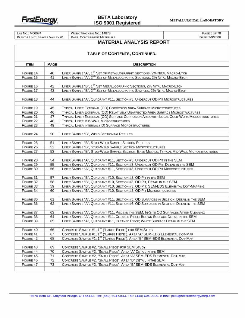
TABLE OF CONTENTS, CONTINUED.
ITEM PAGE DESCRIPTION
FIGURE 14 40 LINER SAMPLE “A”, 1ST SET OF METALLOGRAPHIC SECTIONS, 2% NITAL MACRO-ETCH
FIGURE 15 41 LINER SAMPLE “A”, 2ND SET OF METALLOGRAPHIC SECTIONS, 2% NITAL MACRO-ETCH
FIGURE 16 42 LINER SAMPLE “B”, 1ST SET METALLOGRAPHIC SECTIONS, 2% NITAL MACRO-ETCH
FIGURE 17 43 LINER SAMPLE “B”, 2ND SET OF METALLOGRAPHIC SAMPLES, 2% NITAL MACRO-ETCH
FIGURE 18 44 LINER SAMPLE “A”, QUADRANT #11, SECTION #3, UNDERCUT OD PIT MICROSTRUCTURES
FIGURE 19 45 TYPICAL LINER EXTERNAL (OD) CORROSION AREA SURFACE MICROSTRUCTURES
FIGURE 20 46 TYPICAL LINER EXTERNAL (OD) RELATIVELY UNAFFECTED AREA SURFACE MICROSTRUCTURES
FIGURE 21 47 TYPICAL LINER EXTERNAL (OD) SURFACE CORROSION AREA WITH LOCAL COLD-WORK MICROSTRUCTURES
FIGURE 22 48 TYPICAL LINER MID-WALL MICROSTRUCTURES
FIGURE 23 49 TYPICAL LINER INTERNAL (ID) SURFACE MICROSTRUCTURES
FIGURE 24 50 LINER SAMPLE “B”, WELD SECTIONING RESULTS
FIGURE 25 51 LINER SAMPLE “B”, STUD-WELD SAMPLE SECTION RESULTS
FIGURE 26 52 LINER SAMPLE “B”, STUD-WELD SAMPLE SECTION MICROSTRUCTURES
FIGURE 27 53 LINER SAMPLE “B”, STUD-WELD SAMPLE SECTION, BASE METALS; TYPICAL MID-WALL MICROSTRUCTURES
FIGURE 28 54 LINER SAMPLE “A”, QUADRANT #11, SECTION #3, UNDERCUT OD PIT IN THE SEM FIGURE 29 55 LINER SAMPLE “A”, QUADRANT #11, SECTION #3, UNDERCUT OD PIT, DETAIL IN THE SEMFIGURE 30 56 LINER SAMPLE “A”, QUADRANT #11, SECTION #3, UNDERCUT OD PIT MICROSTRUCTURES
FIGURE 31 57 LINER SAMPLE “B”, QUADRANT #10, SECTION #3, OD PIT IN THE SEMFIGURE 32 58 LINER SAMPLE “B”, QUADRANT #10, SECTION #3, OD PIT, DETAIL IN THE SEMFIGURE 33 59 LINER SAMPLE “B”, QUADRANT #10, SECTION #3, OD PIT; SEM-EDS ELEMENTAL DOT-MAPPING
FIGURE 34 60 LINER SAMPLE “B”, QUADRANT #10, SECTION #3, OD PIT MICROSTRUCTURES
FIGURE 35 61 LINER SAMPLE “A”, QUADRANT #11, SECTION #5; OD SURFACES IN SECTION, DETAIL IN THE SEM FIGURE 36 62 LINER SAMPLE “A”, QUADRANT #11, SECTION #6; OD SURFACES IN SECTION, DETAIL IN THE SEM
FIGURE 37 63 LINER SAMPLE “A”, QUADRANT #11, PIECE IN THE SEM; IN-SITU OD SURFACES AFTER CLEANING
FIGURE 38 64 LINER SAMPLE “A”, QUADRANT #11, CLEANED PIECE; BROWN SURFACE DETAIL IN THE SEMFIGURE 39 65 LINER SAMPLE “A”, QUADRANT #11, CLEANED PIECE; WHITE SURFACE DETAIL IN THE SEM
FIGURE 40 66 CONCRETE SAMPLE #1, 1ST (“LARGE PIECE”) FOR SEM STUDY
FIGURE 41 67 CONCRETE SAMPLE #1, 1ST (“LARGE PIECE”), AREA “A” SEM-EDS ELEMENTAL DOT-MAP
FIGURE 42 68 CONCRETE SAMPLE #1, 1ST (“LARGE PIECE”), AREA “B” SEM-EDS ELEMENTAL DOT-MAP
FIGURE 43 69 CONCRETE SAMPLE #2, “SMALL PIECE” FOR SEM STUDY
FIGURE 44 70 CONCRETE SAMPLE #2, “SMALL PIECE”, AREA “A” DETAIL IN THE SEMFIGURE 45 71 CONCRETE SAMPLE #2, “SMALL PIECE”, AREA “A” SEM-EDS ELEMENTAL DOT-MAP
FIGURE 46 72 CONCRETE SAMPLE #2, “SMALL PIECE”, AREA “B” DETAIL IN THE SEMFIGURE 47 73 CONCRETE SAMPLE #2, “SMALL PIECE”, AREA “B” SEM-EDS ELEMENTAL DOT-MAP
BETA LaboratoryISO 9001 Registered
METALLURGICAL LABORATORY
LAB NO.: M06074 WORK TRACKING NO.: 14878 PAGE 7 OF 78PLANT & UNIT: BEAVER VALLEY #1 PART: CONTAINMENT MATERIALS DATE: 3/9/2006
MATERIAL ANALYSIS REPORT
6670 Beta Dr., Mayfield Village, OH 44143, Tel: (440) 604-9843, Fax: (440) 604-9800, e-mail: [email protected]
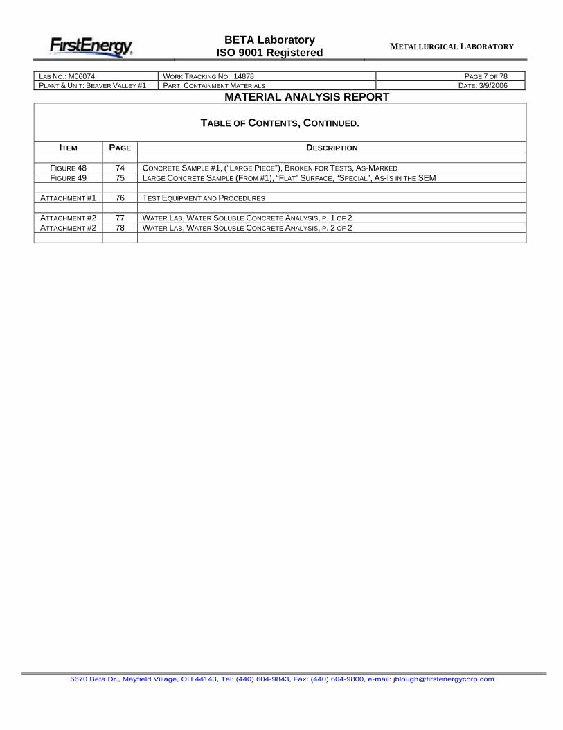
TABLE OF CONTENTS, CONTINUED.
ITEM PAGE DESCRIPTION
FIGURE 48 74 CONCRETE SAMPLE #1, (“LARGE PIECE”), BROKEN FOR TESTS, AS-MARKED
FIGURE 49 75 LARGE CONCRETE SAMPLE (FROM #1), “FLAT” SURFACE, “SPECIAL”, AS-IS IN THE SEM
ATTACHMENT #1 76 TEST EQUIPMENT AND PROCEDURES
ATTACHMENT #2 77 WATER LAB, WATER SOLUBLE CONCRETE ANALYSIS, P. 1 OF 2ATTACHMENT #2 78 WATER LAB, WATER SOLUBLE CONCRETE ANALYSIS, P. 2 OF 2