Embed Size (px)
Citation preview

FHIT - Quick reference guide
May 28, 2002
1
CONTENTS 2
Contents
1 Front-end Hybrid Industrial Tester (FHIT) 31.1 Purposes . . . . . . . . . . . . . . . . . . . . . . . . . . . . . . . . 31.2 FHIT systems . . . . . . . . . . . . . . . . . . . . . . . . . . . . . 31.3 Transition boards . . . . . . . . . . . . . . . . . . . . . . . . . . . 51.4 Component layout and LED code . . . . . . . . . . . . . . . . . . 6
2 FHIT Software (FHITS) 92.1 Introduction . . . . . . . . . . . . . . . . . . . . . . . . . . . . . . 92.2 General description of subtests and other features . . . . . . . . . 9
2.2.1 Connectivity Test . . . . . . . . . . . . . . . . . . . . . . 92.2.2 Electrical Test . . . . . . . . . . . . . . . . . . . . . . . . 92.2.3 Functional Test . . . . . . . . . . . . . . . . . . . . . . . . 102.2.4 FHITS features . . . . . . . . . . . . . . . . . . . . . . . . 11
2.3 FHITS performances . . . . . . . . . . . . . . . . . . . . . . . . . 11
3 Industrial Test procedure 11
4 Installation 114.1 Hardware identification . . . . . . . . . . . . . . . . . . . . . . . 11
4.1.1 FHIT type . . . . . . . . . . . . . . . . . . . . . . . . . . 124.1.2 Power supply control . . . . . . . . . . . . . . . . . . . . . 12
4.2 Hardware installation . . . . . . . . . . . . . . . . . . . . . . . . 134.3 Software installation (mono- and dual-FHIT) . . . . . . . . . . . 14
4.3.1 FHITS configuration file . . . . . . . . . . . . . . . . . . . 154.4 easy-FHIT . . . . . . . . . . . . . . . . . . . . . . . . . . . . . . . 154.5 Installation summary . . . . . . . . . . . . . . . . . . . . . . . . . 16
4.5.1 mono- and dual-FHIT . . . . . . . . . . . . . . . . . . . . 164.5.2 easy-FHIT . . . . . . . . . . . . . . . . . . . . . . . . . . 17
5 Problems 175.1 Troubleshooting . . . . . . . . . . . . . . . . . . . . . . . . . . . . 175.2 Known bugs . . . . . . . . . . . . . . . . . . . . . . . . . . . . . . 17
6 FHIT working group 17
7 Dictionary 19
8 Appendix 208.1 Serial language to FHIT . . . . . . . . . . . . . . . . . . . . . . . 218.2 CMS label for hybrids . . . . . . . . . . . . . . . . . . . . . . . . 24

1 FRONT-END HYBRID INDUSTRIAL TESTER (FHIT) 3
1 Front-end Hybrid Industrial Tester (FHIT)
1.1 Purposes
The FHIT aims at testing the Front-End Hybrids (FEH) for CMS tracker inthe industry (hybrid manufacturers) and after micro bonding of pitch adapter(CERN). It is a performant application specific device able to carry out threedifferent and complementary tests, a connectivity test (CT), an electrical test(ET) and a functional test(FT), with a low cost relative to old or generic indus-trial tester which are not able to perform easily every test. FHIT is a compactmachine performing automatically and quickly these three tests. The FHITsetup can be used at different stages in the production chain
• as soon as possible, to detect connectivity or electrical problems (open orshort circuits, wrong bondings, ...),
• as late as possible before module assembly, to check that no failure ap-peared during handling (broken lines, ...).
FHIT is an industrial tester but it will also be useful for a quick hybrid testbefore starting deeper and longer tests in a laboratory. So, FHIT will serve bothas an industrial tester and as a fast laboratory tester.
1.2 FHIT systems
Three types of FHIT are available according to specific requirements. They are
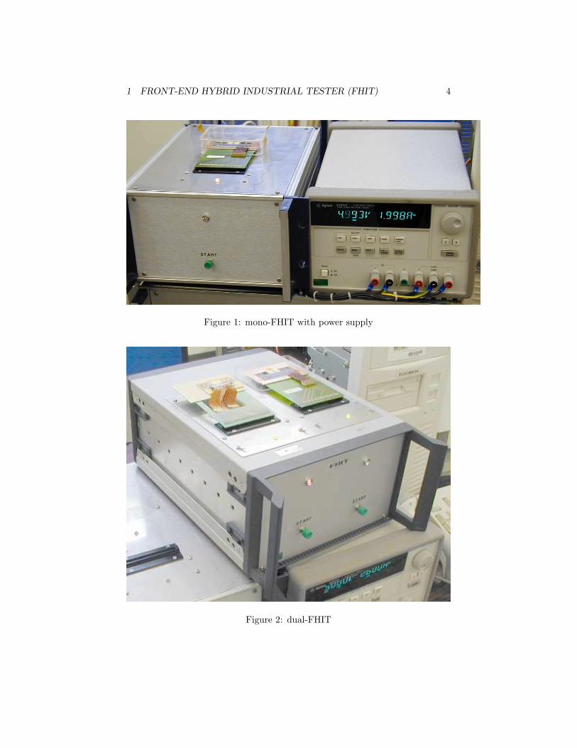
• the mono-FHIT (Figure 1) : this setup is recommended for laboratorypurposes, when a full industrial test (CT, ET and FT) is required, butwhen matters of timing are not critical (few FEH to be tested). Themono-FHIT setup, automatically driven via a specific software, can hostonly one FEH.
• the dual-FHIT (Figure 2) : this setup is recommended for industrieswhich produce or handle a lot of FEH. The dual-FHIT facility is a mergingof two mono-FHIT which gives the possibility to perform consecutive testswithout any deadtime. The dual-FHIT setup is also automatically drivenvia a specific software and can host two FEHs.
• the easy-FHIT : this setup is recommended for laboratories which areworking on developing and debugging the hybrid and which do not needany functional test of FEH. The easy-FHIT setup is an expert user FHIT,with a lot of debugging possibilities and is driven by messages sent by userthrough an hyperterminal. It can host one FEH and performs only CTand ET, as it is not provided with an ARC board.
Both mono- and dual-FHIT can also be run as an easy-FHIT, through an hy-perterminal.
1 FRONT-END HYBRID INDUSTRIAL TESTER (FHIT) 4
Figure 1: mono-FHIT with power supply
Figure 2: dual-FHIT

1 FRONT-END HYBRID INDUSTRIAL TESTER (FHIT) 5
Setup type hosted hybrids ARC board inside performed tests modeeasy-FHIT 1 no CT, ET terminalmono-FHIT 1 yes CT, ET, FT FHITSdual-FHIT 2 yes CT, ET, FT FHITS
Table 1: Setup types and features
Figure 3: Some transition boards (FEHC)
1.3 Transition boards
The FEH are connected to FHIT via a PCB transition board. Every type oftransition boards (TOB/TECbottom, TOB/TECtop, TIBbottom, TIBtop, ...)can be plugged. These transition boards can also serve as hybrid carriers(FEHC), as they are transition boards from the fragile NAIS connector on thehybrid to the robust male SAMTEC connector of FHIT. Some of the availabletransition boards are displayed in Figure 3. These transition boards also allowcooling of the FEH. Furthermore, for a more safety, the FHIT Tool number 1(Figure 5) should be used to easily unplug the hybrid from FHIT. For moreinformation about transition boards, please refer to the FHIT detailed guide[2].
1 FRONT-END HYBRID INDUSTRIAL TESTER (FHIT) 6
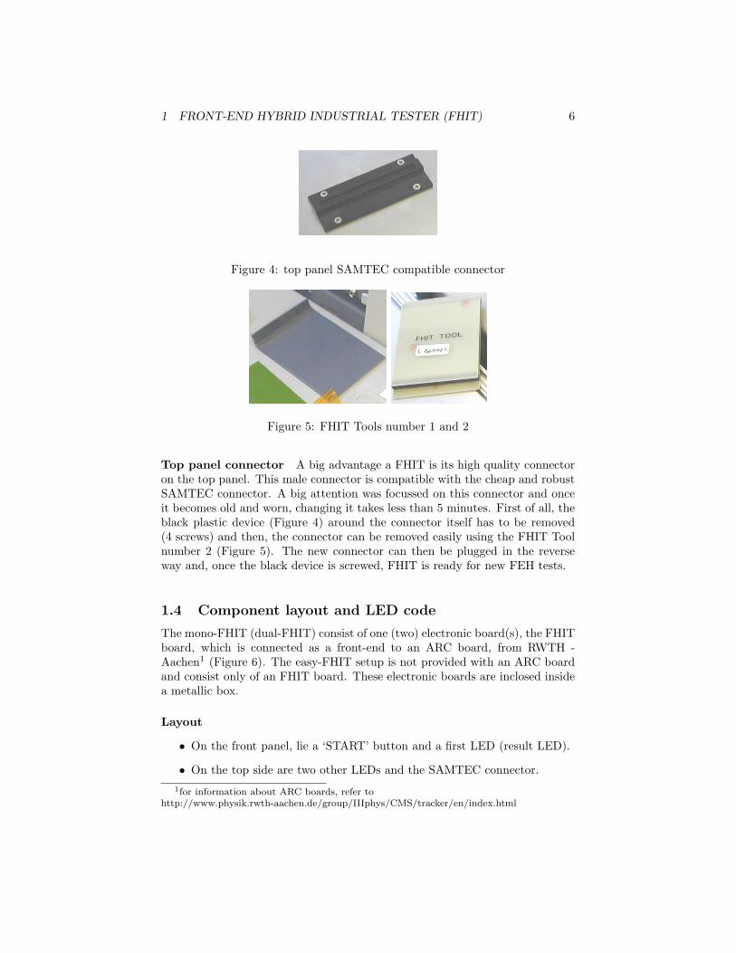
Figure 4: top panel SAMTEC compatible connector
Figure 5: FHIT Tools number 1 and 2
Top panel connector A big advantage a FHIT is its high quality connectoron the top panel. This male connector is compatible with the cheap and robustSAMTEC connector. A big attention was focussed on this connector and onceit becomes old and worn, changing it takes less than 5 minutes. First of all, theblack plastic device (Figure 4) around the connector itself has to be removed(4 screws) and then, the connector can be removed easily using the FHIT Toolnumber 2 (Figure 5). The new connector can then be plugged in the reverseway and, once the black device is screwed, FHIT is ready for new FEH tests.
1.4 Component layout and LED code
The mono-FHIT (dual-FHIT) consist of one (two) electronic board(s), the FHITboard, which is connected as a front-end to an ARC board, from RWTH -Aachen1 (Figure 6). The easy-FHIT setup is not provided with an ARC boardand consist only of an FHIT board. These electronic boards are inclosed insidea metallic box.
Layout
• On the front panel, lie a ‘START’ button and a first LED (result LED).
• On the top side are two other LEDs and the SAMTEC connector.1for information about ARC boards, refer to
http://www.physik.rwth-aachen.de/group/IIIphys/CMS/tracker/en/index.html

1 FRONT-END HYBRID INDUSTRIAL TESTER (FHIT) 7
Figure 6: FHIT (top) and ARC (bottom) boards - inside the FHIT box

1 FRONT-END HYBRID INDUSTRIAL TESTER (FHIT) 8
Figure 7: FHIT top, front and rear panels
LED Function Color MeaningFront IT Result Green Grade A hybrid
Blinking green Grade B hybridOrange Grade C hybrid (if defined)Blinking orange Grade D hybrid (if defined)Red Bad hybridBlinking red Test failed (fatal error)OFF Hybrid ID performed
Top Info Green Hybrid (un)plugging allowedOrange Waiting for information; FEH (un)plugging allowedRed FEH powered ON : unplugging NOT allowed
All Blinking red FHIT powered ON with FEH connected
Table 2: LED color code
• On the back side lie the RS232 connector, the power supply input, themode switch2 and the reset button.
The industrial test global result will be displayed on the front panel LED whereasthe other LED indicates whether it is possible to plug or unplug the hybrid. Themeaning of LED colors is provided in Table 2.The result LED (front panel) provides user with information about industrialtest result (hybrid grade3 or fatal error). When the top LEDs are Green orOrange, user is authorized to plug or unplug the hybrid. On the other hand,when it is red, hybrid is powered and the FEH should not be removed. WhenFHIT is powered ON, no hybrid is supposed to be plugged. Otherwise, LED willblink Red and a power OFF followed by hybrid unplugging will be necessarybefore proper power ON. Indeed, the FHIT self check makes sure that supplieshave the correct values. If it is not the case, no hybrid should be powered ON,
2to run or program FHIT3refer to [1] for information about hybrid grades
2 FHIT SOFTWARE (FHITS) 9
as it could be dangerous for it. This explains why no FEH should be pluggedduring FHIT self check (after FHIT power on or after a press on the RESETbutton).
2 FHIT Software (FHITS)
2.1 Introduction
The following section is only for mono- and dual-FHIT. The Industrial Testconsists in three subtests :
• the Connectivity Test (CT): searches for short or open circuits, bad con-nections, ...
• the Electrical Test (ET): checks supplies, access to registers, current con-sumption, performs a DCU calibration, ...
• the Functional Test (FT): tests chip functionalities, measures pedestal,noise, response to a calibration pulse, ...
To perform these tests, the Industrial Tester Software (FHITS) has been writtenwith LabVIEW 6.0 for Windows 98. FHITS will work as an interface gatheringinformation from subtests and as a controller (power supply remote controller,scanner driver, local file generator, ...). The FHITS software is the same formono- and dual-FHIT. The user simply has to change one parameter4 in theconfiguration file to choose between mono- or dual-FHIT (see section 4.3.1 formore details on the configuration file).
2.2 General description of subtests and other features
2.2.1 Connectivity Test
This is the first part of the IT. It consists in a passive test, without power supplyconnected. Each pin of the FEH connector is tested in order to find open orshort circuit. Connectivity test is performed 10 times if everything is OK. Thislasts less than 5 seconds.
2.2.2 Electrical Test
This test is the second part of IT. It includes tests of power supply currents andvoltages; test of access to I2C chips, including DCU, PLL, MUX and APV’s.During the electrical test, a DCU calibration and linearity check are also per-formed. Both connectivity and electrical tests allow finding most of errors onFEH. Electrical test is performed with different hybrid supply values (nominal,maximal and minimal voltages).
4** FHIT type::1** is for mono-FHIT and ** FHIT type::2** is for dual-FHIT

2 FHIT SOFTWARE (FHITS) 10
Figure 8: FHITS screenshot
2.2.3 Functional Test
This is the last part of IT. The hybrid is now controlled by the ARC board. Thealgorithms of the functional test5 are performed in C++ and applied thanks toa LabVIEW interface (standard dll call). The functional test includes :
• ARC board self test
• APV I2C access test
• APV data output test
• MUX response test
• Pedestal and noise tests
• Calibration pulse test
During the functional test, access and full functionality of chips present on thehybrid are tested, as well as output quality through the pedestal, noise andcalibration tests that give information on the bad channels6. Full details aboutthese tests are given in the detailed guide [2].
5functional test is a part of ARCS software from RWTH Aachen6refer to [1] for further information about bad channel definition
3 INDUSTRIAL TEST PROCEDURE 11
2.2.4 FHITS features
FHITS
• can remotely control the power supply (if available, hardware dependent)
• manages the dialog between computer and FHIT
• drives the barcode scanner
• gathers information from CT, ET and FT
• computes the hybrid grade
• creates a log file which could become a database stored XML file.
2.3 FHITS performances
FHITS was developed with
• TOB/TEC bottom, TIB top and a TOB/TEC top hybrids provided witha DCU2 and 4 APVs
• a ISA board connection to ARC
• mono-FHIT and dual-FHIT setups
The global industrial test duration is always less than 100 seconds. This timeis needed in order to perform CT, ET and FT with a 1000 data acquisition perAPV and a calibration pulse test.
3 Industrial Test procedure
Performing an industrial test is easy. Once FHITS has started without any hy-brid on FHIT, the user has to plug an hybrid and to scan its barcode. After lessthan two minutes FHIT will give the hybrid grade. As soon as an industrial testhas ended, the user can plug and scan a new hybrid or quit FHITS by clickingthe END button. Some features are set in the configuration file (ITS init.cfg),which has to be in the c:\FHIT folder. More information about FHITS is givenin the detailed guide [2].
4 Installation
This section will give only the steps to quickly install a FHIT setup.
4.1 Hardware identification
First of all, the user have to identify the available hardware, so that the setupprocedure will be correctly described.
4 INSTALLATION 12
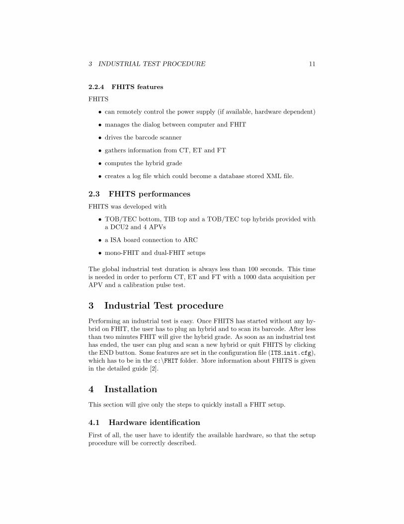
Figure 9: mono-FHIT rear panel (with flat wire)
4.1.1 FHIT type
There are three different type of FHIT : easy-FHIT, mono-FHIT and dual-FHIT.
dual-FHIT has two connectors on the top panel (Figure 2).
mono-FHIT has only one connector (Figure 1).
easy-FHIT has one connector on the top panel and flat wire7 going out fromrear panel.
4.1.2 Power supply control
There are three way to control the power supply.
• GPIBUS remote control
• serial remote control
• manual control
Remote control is safer for the hardware as it prevents from doing manuallysomething wrong. For a remote control, two things are needed :
• An Agilent HP313x power supply7See Figure 9
4 INSTALLATION 13
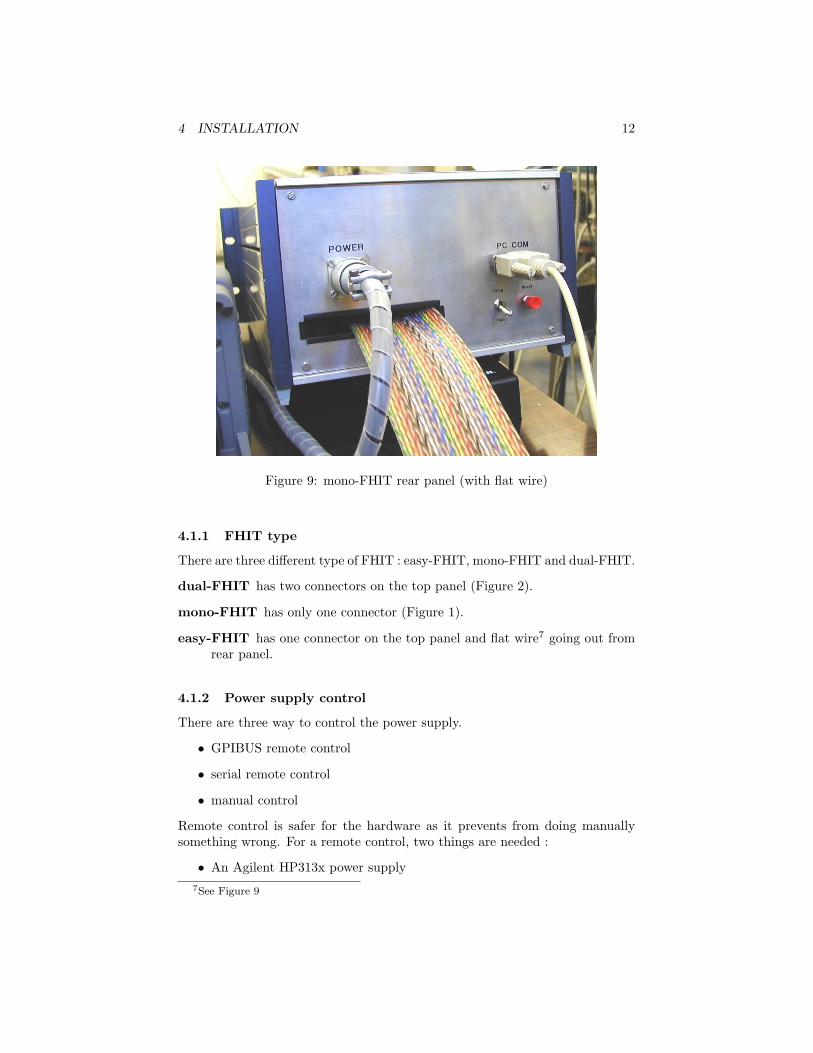
FHIT Scanner PS control FHIT A FHIT B Needed boardmono COM1 GPIBUS COM 2 - GPIBUSdual COM 5 COM 6 GPIBUS + COM extmono COM 2 COM 5 - COM extdual COM 5 COM 6 COM extmono manual COM 2 - -easy COM 2 - -dual COM 5 COM 6 COM ext
Table 3: Connection table
• Either a GPIBUS controller board (not provided) or a free COM port(serial extension board can be provided)
4.2 Hardware installation
Power supply The needed voltages are +5V, +12V, -5V. Check that everyGND are tied altogether. Power supply output is supposed to be gathered inthe rounded connector (Figure 9). For remote control (Agilent HP313x powersupply only), the input (serial or GPIBUS, depending on your system) has alsoto be connected to computer via the proper wire. Be careful that no fuse ispresent on FHIT, this is therefore the current limitation of the power supplywhich avoids electronics to get to much current.
Barcode scanner The barcode scanner used for FHIT is a serial one (Dat-alogic Gryphon D200) and has to be plugged on COM 1, according to Table3.
FHIT Make sure that the mode switch is in RUN position and that the fol-lowing wires are plugged :
• power supply (rear panel; rounded connector)
• communication wire(s) (back side; to PC COM) ; refer to Table 3 for moreinformation
• flat wire (back side; to PC ISA board; mono- and dual-FHIT only)
To know how to connect your FHIT and power supply remote control wires,refer to Table 3. If it is needed to change the configuration, using differentCOM ports than in Table 3, the configuration file can be changed.
Serial port extension board (if needed) This plug-and-play board has tobe inserted into a free PCI slot. Please have a look in the board documentationfor more information.

4 INSTALLATION 14
Figure 10: ITSetup.zip download
4.3 Software installation (mono- and dual-FHIT)
Industrial Tester Software Installation The FHITS installation is easy.The first thing is to download the installation files from
http://www.fynu.ucl.ac.be/themes/he/cms/activities/tracker/hybrids.html.
Just click on the ‘[zip]’ link in the ‘FHITS executable’ section and the downloadof ‘FHITSsetup.zip’ will begin.
The zip file has been created from WinZIP. Once the download is completed,unzip the file into a temporary folder and run the ‘Setup.exe’ executable file.This will install first FHITS itself and then the LabVIEW Run-Time Engine intothe chosen folders. Take care that the LabVIEW Run-Time Engine is needed.Once the setup is completed, the FHITS is ready to run.
mono-FHIT and dual-FHIT After downloading and unzipping the instal-lation files, run ‘setup.exe’. This will install both the Industrial Tester Software(FHITS) and the LabVIEW Run-Time Engine (which is needed) into the chosenfolders. Once this installation has been completed, the user still has to createthe folder C:\FHIT and to copy and paste ITS init.cfg into this folder. Af-ter these steps, check the parameters from the configuration file (Section 4.3.1)
4 INSTALLATION 15
and then run ‘IndustrialTest.exe’. The industrial test will start as explained insection 3.
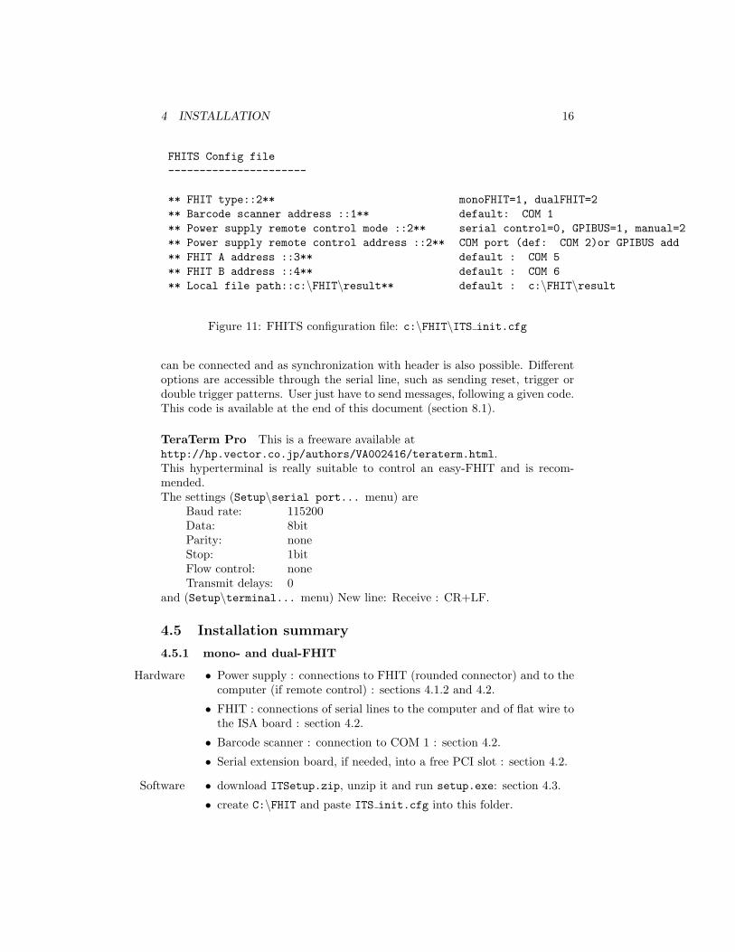
4.3.1 FHITS configuration file
This file contains some features that could be changed when needed. For in-stance, the different COM ports can be changed there, as well as the powersupply control mode or the log file path. An example of this configuration fileis shown in Figure 11.
• FHIT type::2 defines whether a mono-FHIT or a dual-FHIT has to becontrolled by FHITS.
mono-FHIT FHIT type::1dual-FHIT FHIT type::2
• Barcode scanner address ::1 defines the COM port for the serial bar-code scanner. In this case 1 means COM 1.
• Power supply remote control mode ::2 defines the power supply con-trol mode.serial remote control ...control mode ::0GPIBUS remote control ...control mode ::1manual control ...control mode ::2
• Power supply remote control address ::2 defines the COM port orGPIBUS address for power supply remote control.
• FHIT A address ::3 defines the COM port for FHIT A. FHIT A corre-sponds to the FHIT inside a mono-FHIT or to the left-hand FHIT insidea dual-FHIT.
• FHIT B address ::4 defines the COM port for the right-hand FHIT in-side a dual-FHIT.
• Local file path::c:\FHIT\result defines the path to store the log filecreated at the end of an industrial test.
4.4 easy-FHIT
This FHIT setup is an expert user FHIT, able to perform different debug oper-ations. It can not perform a full industrial test as it is not able to perform thefunctional test. So there is no need to install FHITS for an easy-FHIT as it won’tbe able to use it. The only thing is to use a basic terminal (as TeraTerm Profor instance) to read what FHIT is writing on the serial line8. The easy-FHITsetup allows easy access to signal through an oscilloscope as probe connections
8COM settings: Baud rate: 115200; data: 8bit; Parity: none; Stop: 1bit; Flow control:none
4 INSTALLATION 16
FHITS Config file----------------------
** FHIT type::2** monoFHIT=1, dualFHIT=2** Barcode scanner address ::1** default: COM 1** Power supply remote control mode ::2** serial control=0, GPIBUS=1, manual=2** Power supply remote control address ::2** COM port (def: COM 2)or GPIBUS add** FHIT A address ::3** default : COM 5** FHIT B address ::4** default : COM 6** Local file path::c:\FHIT\result** default : c:\FHIT\result
Figure 11: FHITS configuration file: c:\FHIT\ITS init.cfg
can be connected and as synchronization with header is also possible. Differentoptions are accessible through the serial line, such as sending reset, trigger ordouble trigger patterns. User just have to send messages, following a given code.This code is available at the end of this document (section 8.1).
TeraTerm Pro This is a freeware available athttp://hp.vector.co.jp/authors/VA002416/teraterm.html.This hyperterminal is really suitable to control an easy-FHIT and is recom-mended.The settings (Setup\serial port... menu) are
Baud rate: 115200Data: 8bitParity: noneStop: 1bitFlow control: noneTransmit delays: 0
and (Setup\terminal... menu) New line: Receive : CR+LF.
4.5 Installation summary
4.5.1 mono- and dual-FHIT
Hardware • Power supply : connections to FHIT (rounded connector) and to thecomputer (if remote control) : sections 4.1.2 and 4.2.
• FHIT : connections of serial lines to the computer and of flat wire tothe ISA board : section 4.2.
• Barcode scanner : connection to COM 1 : section 4.2.
• Serial extension board, if needed, into a free PCI slot : section 4.2.
Software • download ITSetup.zip, unzip it and run setup.exe: section 4.3.
• create C:\FHIT and paste ITS init.cfg into this folder.

5 PROBLEMS 17
• check the configuration file parameters : section 4.3.1.
• run IndustrialTest.exe
4.5.2 easy-FHIT
Hardware same procedure as for mono- and dual-FHIT
Software download TeraTermPro software, configure and run it : section 4.4.
5 Problems
5.1 Troubleshooting
1. If FHIT serial connection is bad, no industrial test will be performed. Justafter power on, FHITS proceeds in an automatic check of this connectionby sending a message through the serial line and by listening to FHITresponse. If wires are not plugged or if real COM port is not the same asthe COM port from configuration file, no access to FHIT will be possiblefrom computer and FHITS will automatically stops, after complaining.
2. If the configuration file ITS init.cfg is not found, FHITS won’t properlywork. This file has to lie in the c:\FHIT folder.
5.2 Known bugs
No bug has been discovered yet.
6 FHIT working group
FHIT project is carried by UCL (Louvain-la-Neuve).
• Luc Bonnet, [email protected]
• Vincent Lemaitre, [email protected]
• Xavier Rouby, [email protected]
This work is performed in collaboration with RWTH (Aachen) and IReS (Stras-bourg).
• Definition of CT and ET:
– Jean-Daniel Berst, [email protected]
– Ulrich Goerlach, [email protected]
• Functional test, ARC board use:
– Markus Axer, [email protected]

6 FHIT WORKING GROUP 18
– Franz Beissel, [email protected]
– Torsten Franke, [email protected]
– Joachim Mnich, [email protected]
For information or comments, contact Vincent Lemaitre : [email protected]

7 DICTIONARY 19
7 Dictionary
dual-FHIT : Two hybrid FHIT
CR : Carriage Return character
CT : Connectivity Test, first part of IT
ET : Electrical Test, second part of IT
easy-FHIT : mono-FHIT without ARC board (CT & ET only)
FE : Front-End (ARC-FE or FHIT)
FEH : Front-End Hybrid
FEHC : FEH Carrier, ie, the transition board
FHIT : Front-End Hybrid Industrial Tester
FT : Functional Test, third part of IT
IT : Industrial Test (CT, ET, FT)
FHITS : FHIT Software
mono-FHIT : One hybrid FHIT
PS : Power Supply
UCL : Universite Catholique de Louvain

8 APPENDIX 20
8 Appendix
This appendix gathers :
• the bibliography
• the code for serial messages sent to FHIT (easy-FHIT setup)
• the standard labelsuser by the CMS collaboration for FEH barcode.
References
[1] L. Demaria,M. Meschini, F. Hartman, G. Dirkes: Procedures for ModuleTest - Draft 1, 18p (26/02/02)
[2] FHIT group: FHIT detailed guide

REFERENCES 21
8.1 Serial language to FHIT
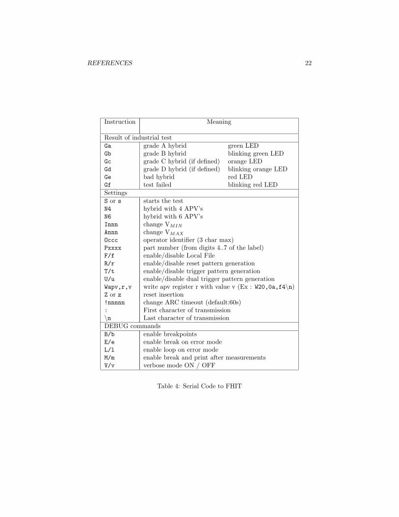
FHIT and the computer communicate via the serial line. FHITS simply readswhat FHIT is sending through the line, whatever it sends. In turn, FHITS cansend well-defined messages to FHIT in the same way, but these messages mustfollow a given code. This code is written here. This code won’t be useful foruser, unless an easy-FHIT is used.
Before the beginning of the industrial test, the hybrid has to be identified (byscanning it). This will provide FHIT with some information about the hybrid(TIB or TOB), the FEHC board (TOP or BOTTOM) and the number of APV’son the hybrid. All the information needed is sent to FHIT with different char-acters, defined in Table 4. Please note that this language is case sensitive. Thestring always begins with the ‘:’ character and ends with ‘\n’ character. Inbetween lie the different instructions9.
At the end of the industrial test, another message will be sent to FHIT, givingit the final result of the test from four different values10 : Grade A, Grade B,Bad Hybrid or Test Failed. Here is the sent character.
“A” Grade A: if hybrid has less than 0.2% bad channels
“B” Grade B: if hybrid has less than 0.5% bad channels
“E” Bad Hybrid: if more than 0.5% bad channels or any of MUX/PLL/DCUor APV25 fails
“F” Test Failed: if a fatal error occurred during the test
The characters “C” and “D” are free so they can be used if more hybrid gradesare necessary in the future.
The summary of the code (and the corresponding Front LED color11 whenmeaningful) is available in the Table 4.
Important things :
• every message must start with the : character and finish with \n12.
• sending : remove every other character written after the last CR. So anymistake in the message can be corrected by rewriting the whole messagebefore pressing CR.
• CT and ET can start after having plug an hybrid (top panel LED isOrange) by sending the message :Pxxxx\n, where xxxx has to be replaceby the correct part number relative to the FEH.
9example : ‘:P1664s\n’ sends the part number 1664 and starts the industrial test10the hybrid grade definition is provided by [1], p1011for further details on the LED color, please have a look at Table 212With TeraTerm Pro, the \n is generated by a CR (press Enter)
REFERENCES 22
Instruction Meaning
Result of industrial testGa grade A hybrid green LEDGb grade B hybrid blinking green LEDGc grade C hybrid (if defined) orange LEDGd grade D hybrid (if defined) blinking orange LEDGe bad hybrid red LEDGf test failed blinking red LEDSettingsS or s starts the testN4 hybrid with 4 APV’sN6 hybrid with 6 APV’sInnn change VMIN
Annn change VMAX
Occc operator identifier (3 char max)Pxxxx part number (from digits 4..7 of the label)F/f enable/disable Local FileR/r enable/disable reset pattern generationT/t enable/disable trigger pattern generationU/u enable/disable dual trigger pattern generationWapv,r,v write apv register r with value v (Ex : W20,0a,f4\n)Z or z reset insertion!nnnnn change ARC timeout (default:60s): First character of transmission\n Last character of transmissionDEBUG commandsB/b enable breakpointsE/e enable break on error modeL/l enable loop on error modeM/m enable break and print after measurementsV/v verbose mode ON / OFF
Table 4: Serial Code to FHIT

REFERENCES 23
• after the end of ET, FHIT is waiting to the hybrid grade to display on itsfront LED (result LED). So, user has to send either a grade message (as:Ga\n) or press the Start button
REFERENCES 24
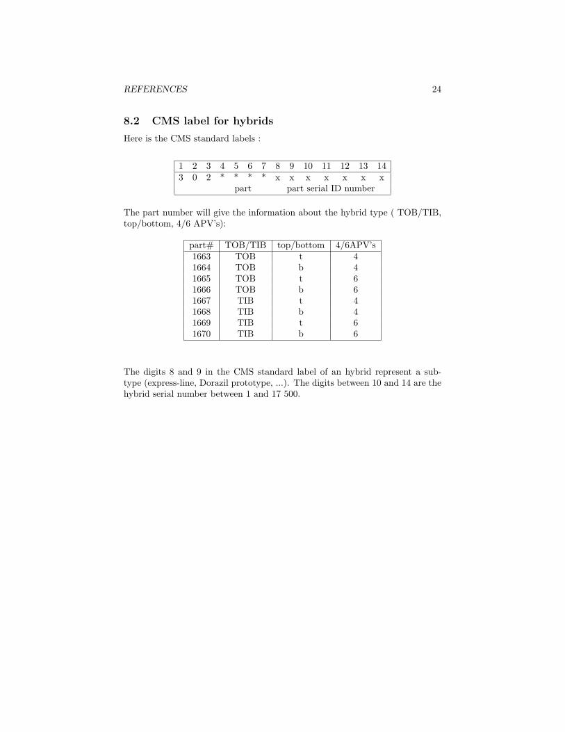
8.2 CMS label for hybrids
Here is the CMS standard labels :
1 2 3 4 5 6 7 8 9 10 11 12 13 143 0 2 * * * * x x x x x x x
part part serial ID number
The part number will give the information about the hybrid type ( TOB/TIB,top/bottom, 4/6 APV’s):
part# TOB/TIB top/bottom 4/6APV’s1663 TOB t 41664 TOB b 41665 TOB t 61666 TOB b 61667 TIB t 41668 TIB b 41669 TIB t 61670 TIB b 6
The digits 8 and 9 in the CMS standard label of an hybrid represent a sub-type (express-line, Dorazil prototype, ...). The digits between 10 and 14 are thehybrid serial number between 1 and 17 500.


![CCNP BCMSN Quick Reference Sheets - Lagout Quick Reference... · CCNP BCMSN Quick Reference Sheets Exam 642-812 ... [ 4 ] CCNP BCMSN Quick Reference Sheets. ... switch would be used](https://img.pdfslide.net/doc/110x75/5a7a6ec87f8b9a05538dccf5/ccnp-bcmsn-quick-reference-sheets-lagout-quick-referenceccnp-bcmsn-quick-reference.jpg)