Embed Size (px)
Citation preview
102 Wright Brothers AveLivermore, CA 94551www.ariatech.com
Phone (925) 447-7500Fax (925) [email protected]
Fiber Optic Product CatalogResources DS-BS-1 01/24/2018
164
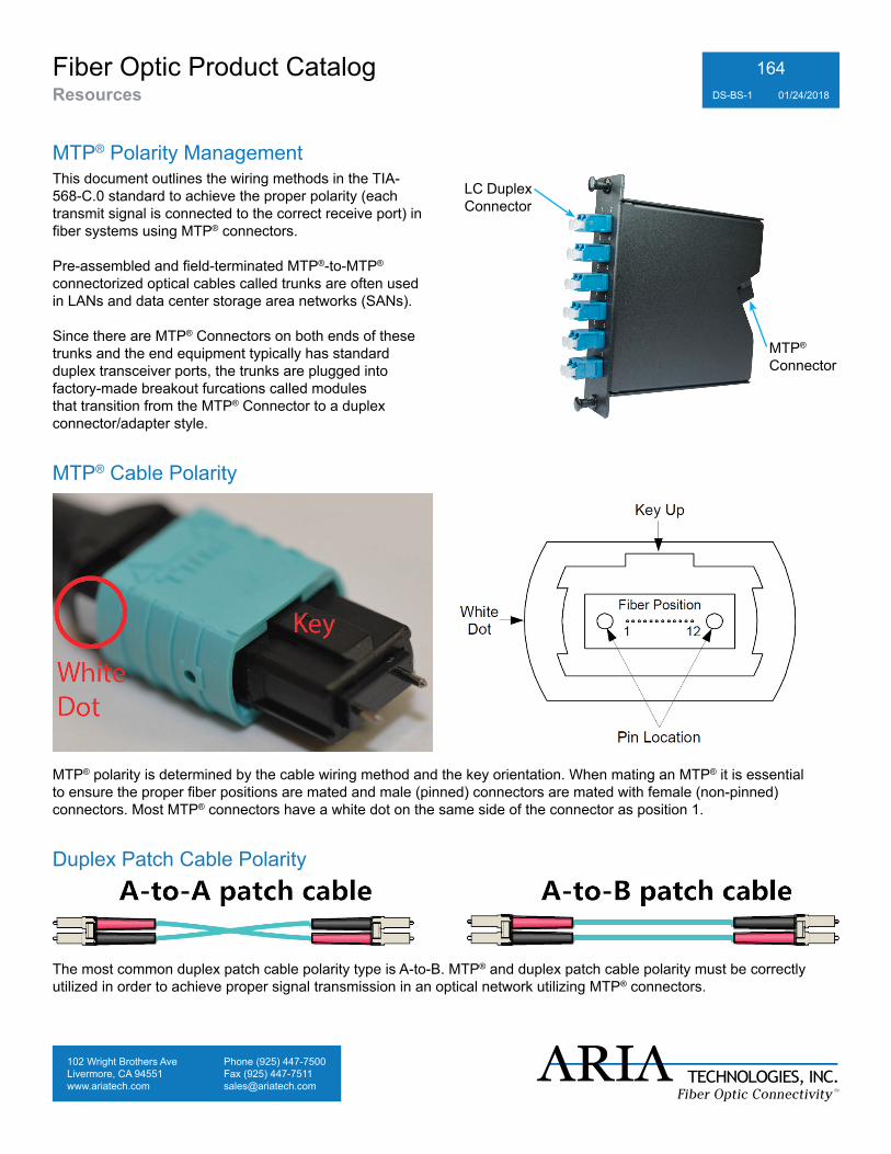
MTP® Polarity ManagementLC DuplexConnector
MTP® Connector
This document outlines the wiring methods in the TIA-568-C.0 standard to achieve the proper polarity (each transmit signal is connected to the correct receive port) in fiber systems using MTP® connectors.
Pre-assembled and field-terminated MTP®-to-MTP® connectorized optical cables called trunks are often used in LANs and data center storage area networks (SANs).
Since there are MTP® Connectors on both ends of these trunks and the end equipment typically has standard duplex transceiver ports, the trunks are plugged into factory-made breakout furcations called modules that transition from the MTP® Connector to a duplex connector/adapter style.
Duplex Patch Cable Polarity
The most common duplex patch cable polarity type is A-to-B. MTP® and duplex patch cable polarity must be correctly utilized in order to achieve proper signal transmission in an optical network utilizing MTP® connectors.
MTP® Cable Polarity
MTP® polarity is determined by the cable wiring method and the key orientation. When mating an MTP® it is essential to ensure the proper fiber positions are mated and male (pinned) connectors are mated with female (non-pinned) connectors. Most MTP® connectors have a white dot on the same side of the connector as position 1.
102 Wright Brothers AveLivermore, CA 94551www.ariatech.com
Phone (925) 447-7500Fax (925) [email protected]
Fiber Optic Product CatalogResources DS-BS-1 01/24/2018
165
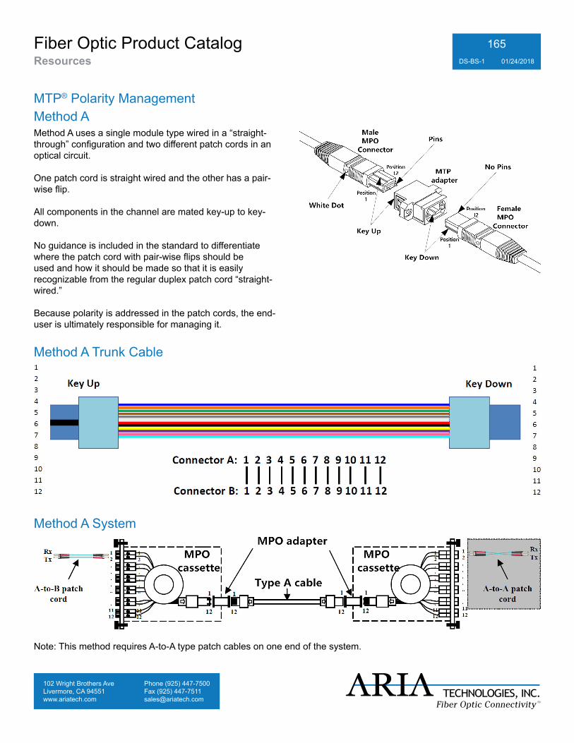
Method AMethod A uses a single module type wired in a “straight-through” configuration and two different patch cords in an optical circuit.
One patch cord is straight wired and the other has a pair-wise flip.
All components in the channel are mated key-up to key-down.
No guidance is included in the standard to differentiate where the patch cord with pair-wise flips should be used and how it should be made so that it is easily recognizable from the regular duplex patch cord “straight-wired.”
Because polarity is addressed in the patch cords, the end-user is ultimately responsible for managing it.
MTP® Polarity Management
Method A Trunk Cable
Method A System
Note: This method requires A-to-A type patch cables on one end of the system.
102 Wright Brothers AveLivermore, CA 94551www.ariatech.com
Phone (925) 447-7500Fax (925) [email protected]
Fiber Optic Product CatalogResources DS-BS-1 01/24/2018
166
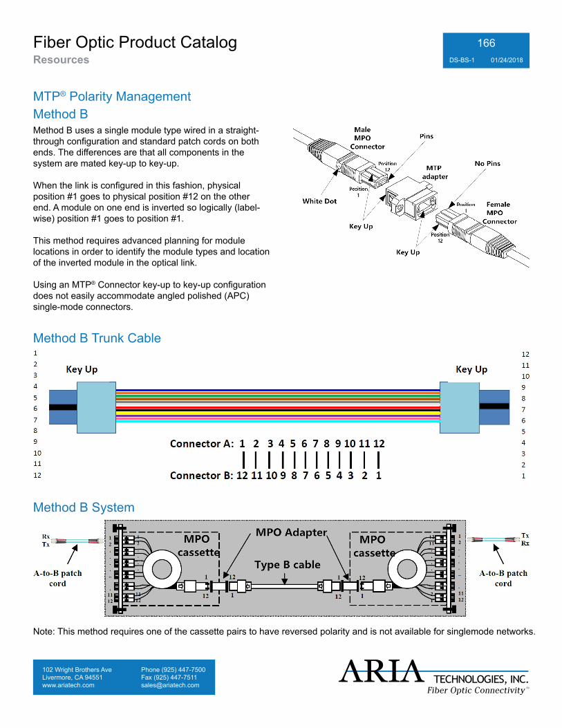
Method BMethod B uses a single module type wired in a straight-through configuration and standard patch cords on both ends. The differences are that all components in the system are mated key-up to key-up.
When the link is configured in this fashion, physical position #1 goes to physical position #12 on the other end. A module on one end is inverted so logically (label-wise) position #1 goes to position #1.
This method requires advanced planning for module locations in order to identify the module types and location of the inverted module in the optical link.
Using an MTP® Connector key-up to key-up configuration does not easily accommodate angled polished (APC) single-mode connectors.
MTP® Polarity Management
Method B Trunk Cable
Method B System
Note: This method requires one of the cassette pairs to have reversed polarity and is not available for singlemode networks.
102 Wright Brothers AveLivermore, CA 94551www.ariatech.com
Phone (925) 447-7500Fax (925) [email protected]
Fiber Optic Product CatalogResources DS-BS-1 01/24/2018
167
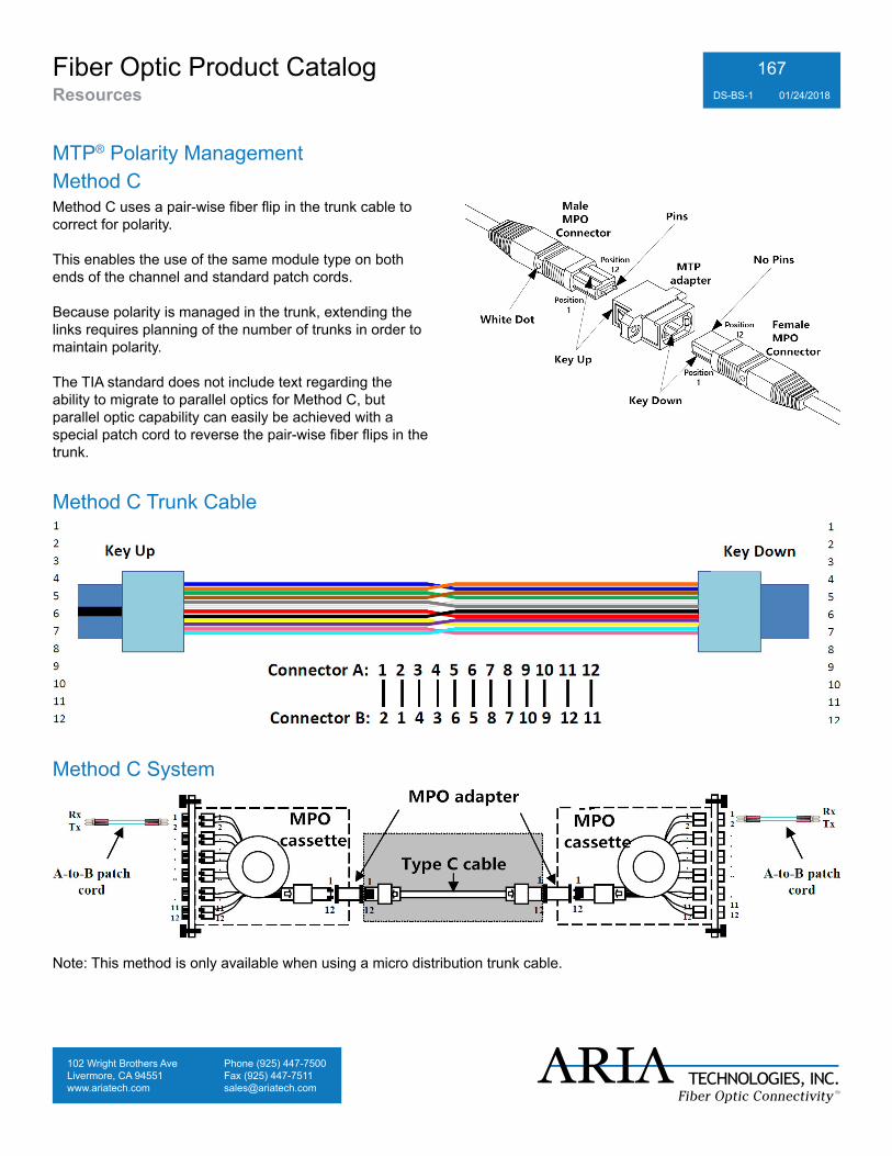
Method CMethod C uses a pair-wise fiber flip in the trunk cable to correct for polarity.
This enables the use of the same module type on both ends of the channel and standard patch cords.
Because polarity is managed in the trunk, extending the links requires planning of the number of trunks in order to maintain polarity.
The TIA standard does not include text regarding the ability to migrate to parallel optics for Method C, but parallel optic capability can easily be achieved with a special patch cord to reverse the pair-wise fiber flips in the trunk.
MTP® Polarity Management
Method C Trunk Cable
Method C System
Note: This method is only available when using a micro distribution trunk cable.