Embed Size (px)
Citation preview
R-FPMI-03
A-09/07
-1500e
x
COUPLINGSAND ADAPTORS
SAINT-GOBAIN PAM21, avenue Camille Cavallier - BP 129 - 54705 PONT-A-MOUSSONCEDEX - France
Tel. : +33 (0)3 83 80 67 89 - Fax International Department : +33 (0)3 83 80 07 04 - Fax Marketing Department : +33 (0)3 83 80 07 17www.pamline.fr
Edition0
9-2007
C0.0/1
COUPLINGS AND ADAPTORS
The couplings, adaptors and sleeves from SAINT-GOBAIN CANALISATION are designed :
- To connect valve equipments to pipes or tubes,• In order to make easier the installation of new valves and to replace old ones when maintaining networks.• When installing valves in new networks located in cluttered subsoils or when installing valves in chambers, in water treatmentplants.
- To connect two pipes or two tubes to each other.
- To repair damage to pipes or tubes and so reduce the water losses.
- To make easier the installation and the dismantling of valve equipments.• When installing double-flanged valves, in order to make easier further dismantling for their maintenance outside the trench or thevalve chamber.
The networks are frequently composed of pipes or tubes of different materials : grey iron, ductile iron, steel, fibre cement, PVC, PE.The range of couplings, adaptors and sleeves from SAINT-GOBAIN CANALISATION has the right answer to most of the connectionand repair needs, whether with products designed for multi materials or whether with dedicated products.
Of low weight and dimensions and very easy to install, the couplings, adaptors and sleeves from SAINT-GOBAIN CANALISATION aredivided into several generic families :
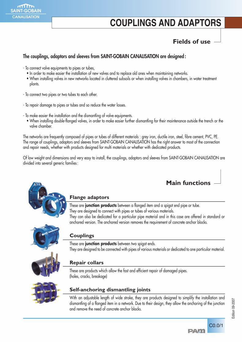
Flange adaptors
These are junction products between a flanged item and a spigot end pipe or tube.They are designed to connect with pipes or tubes of various materials.They can also be dedicated for a particular pipe material and in this case are offered in standard oranchored version. The anchored version removes the requirement of concrete anchor blocks.
Couplings
These are junction products between two spigot ends.They are designed to be connected with pipes of various materials or dedicated to one particular material.
Repair collars
These are products which allow the fast and efficient repair of damaged pipes.(holes, cracks, breakage)
Self-anchoring dismantling joints
With an adjustable length of wide stroke, they are products designed to simplify the installation anddismantling of a flanged item in a network. Due to their design, they allow the anchoring of the junctionand remove the need of concrete anchor blocks.
Fields of use
Main functions
Edition0
9-2007
COUPLINGS AND ADAPTORS
C0.0/2
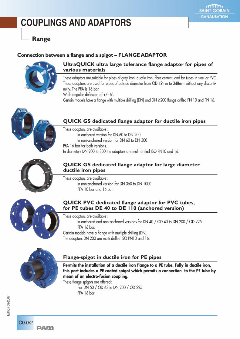
Connection between a flange and a spigot – FLANGEADAPTOR
Range
UltraQUICK ultra large tolerance flange adaptor for pipes ofvarious materials
These adaptors are suitable for pipes of grey iron, ductile iron, fibre-cement, and for tubes in steel or PVC.These adaptors are used for pipes of outside diameter from OD 49mm to 348mm without any disconti-nuity. The PFA is 16 bar.Wide angular deflexion of +/- 6°.Certain models have a flange with multiple drilling (DN) and DN ≥200 flange drilled PN 10 and PN 16.
QUICK GS dedicated flange adaptor for ductile iron pipes
These adaptors are available :In anchored version for DN 60 to DN 200In non-anchored version for DN 60 to DN 300
PFA 16 bar for both versions.In diameters DN 200 to 300 the adaptors are multi drilled ISO PN10 and 16.
QUICK GS dedicated flange adaptor for large diameterductile iron pipes
These adaptors are available :In non-anchored version for DN 350 to DN 1000PFA 10 bar and 16 bar.
QUICK PVC dedicated flange adaptor for PVC tubes,for PE tubes DE 40 to DE 110 (anchored version)
These adaptors are available :In anchored and non-anchored versions for DN 40 / OD 40 to DN 200 / OD 225PFA 16 bar.
Certain models have a flange with multiple drilling (DN).The adaptors DN 200 are multi drilled ISO PN10 and 16.
Flange-spigot in ductile iron for PE pipes
Permits the installation of a ductile iron flange to a PE tube. Fully in ductile iron,this part includes a PE coated spigot which permits a connection to the PE tube bymean of an electro-fusion coupling.These flange-spigots are offered :
For DN 50 / OD 63 to DN 200 / OD 225PFA 16 bar
Edition0
9-2007
ROBINETS-VANNES EURO 20
Diagrams, drawings and propositions of assembly are not contractual
COUPLINGS AND ADAPTORS
C0.0/3
Range
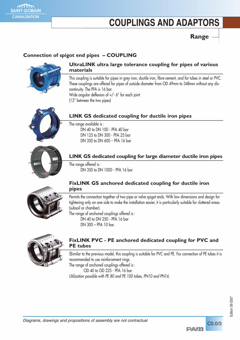
Connection of spigot end pipes – COUPLING
UltraLINK ultra large tolerance coupling for pipes of variousmaterials
This coupling is suitable for pipes in grey iron, ductile iron, fibre-cement, and for tubes in steel or PVC.These couplings are offered for pipes of outside diameter from OD 49mm to 348mm without any dis-continuity. The PFA is 16 bar.Wide angular deflexion of +/- 6° for each joint(12° between the two pipes)
LINK GS dedicated coupling for ductile iron pipes
The range available is :DN 40 to DN 100 - PFA 40 barDN 125 to DN 300 - PFA 25 barDN 350 to DN 600 – PFA 16 bar
LINK GS dedicated coupling for large diameter ductile iron pipes
The range offered is :DN 350 to DN 1000 - PFA 16 bar
FixLINK GS anchored dedicated coupling for ductile ironpipes
Permits the connection together of two pipe or valve spigot ends. With low dimensions and design fortightening only on one side to make the installation easier, it is particularly suitable for cluttered areas(subsoil or chamber).The range of anchored couplings offered is :
DN 40 to DN 250 - PFA 16 barDN 300 – PFA 10 bar.
FixLINK PVC - PE anchored dedicated coupling for PVC andPE tubes
Similar to the previous model, this coupling is suitable for PVC and PE. For connection of PE tubes it isrecommended to use reinforcement rings.The range of anchored couplings offered is :
OD 40 to OD 225 - PFA 16 bar.Utilization possible with PE 80 and PE 100 tubes, PN10 and PN16.
Edition0
9-2007
COUPLINGS AND ADAPTORS
C0.0/4
Range
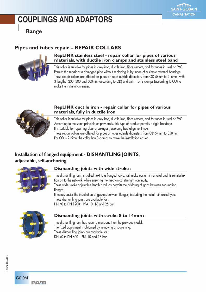
Pipes and tubes repair – REPAIR COLLARSRepLINK stainless steel - repair collar for pipes of variousmaterials, with ductile iron clamps and stainless steel band
This collar is suitable for pipes in grey iron, ductile iron, fibre-cement, and for tubes in steel or PVC.Permits the repair of a damaged pipe without replacing it, by mean of a simple external bandage.These repair collars are offered for pipes or tubes outside diameters from OD 48mm to 516mm, with3 lengths : 200, 300 and 500mm (according to OD) and with 1 or 2 clamps (according to OD) tomake the installation easier.
RepLINK ductile iron - repair collar for pipes of variousmaterials, fully in ductile iron
This collar is suitable for pipes in grey iron, ductile iron, fibre-cement, and for tubes in steel or PVC.According to the same principle as previously, this type of product permits a rigid bandage.It is suitable for repairing clear breakages , avoiding bad alignment risks.These repair collars are offered for pipes or tubes outside diameters from OD 54mm to 358mm.For OD > 215mm the collar has 3 clamps to make the installation easier.
Installation of flanged equipment - DISMANTLING JOINTS,adjustable, self-anchoring
Dismantling joints with wide stroke :
This dismantling joint, installed next to a flanged valve, will make easier its removal and its reinstalla-tion on to the network, while ensuring the mechanical strength continuity.These wide stroke adjustable length products permits the bridging of gaps between two matingflanges.It makes easier the installation of gaskets between flanges, including the metal reinforced type.These dismantling joints are available for :DN 40 to DN 1200 – PFA 10, 16 and 25 bar.
Dismantling joints with stroke 8 to 14mm:
This dismantling joint has lower dimensions than the previous model.The fixed adjustment is obtained by removing a space ring.These dismantling joints are available for :DN 40 to DN 600 – PFA 10 and 16 bar.
The couplings, adaptors and sleeves from SAINT-GOBAIN CANALISATION are internally and externally fusion bonded powder coa-ted, with a minimum thickness of 250microns, in the same manner as for EURO 20 gate valves.
This coating achieves an excellent protection against stresses from soils or carried waters and protects the products from shocks whilehandling before and during installation.
The couplings, adaptors and sleeves from SAINT-GOBAIN CANALISATION are mainly intended for the potable water conveyancemarket.All of their components in contact with the potable water are in accordance with the European regulations and standards (KTW, WRC,DGS approvals).
Edition0
9-2007
COUPLINGS AND ADAPTORS
C0.0/5
Coating
Suitability for potable water
C1.1/1
Edition0
9-2007
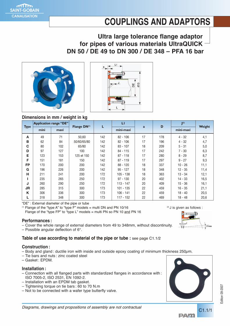
COUPLINGS AND ADAPTORSUltra large tolerance flange adaptor
for pipes of various materials UltraQUICKDN 50 / DE 49 to DN 300 / DE 348 – PFA 16 bar
Performances :– Cover the whole range of external diameters from 49 to 348mm, without discontinuity.– Possible angular deflection of 6°.
Table of use according to material of the pipe or tube : see page C1.1/2Construction :– Body and gland : ductile iron with inside and outside epoxy coating of minimum thickness 250µm.– Tie bars and nuts : zinc coated steel– Gasket : EPDM.
Installation :– Connection with all flanged parts with standardized flanges in accordance with :ISO 7005-2, ISO 2531, EN 1092-2.
– Installation with an EPDM tab gasket.– Tightening torque on tie bars : 60 to 70 N.m– Not to be connected with a wafer type butterfly valve.
Dimensions in mm / weight in kg
Diagrams, drawings and propositions of assembly are not contractual
“DE” : External diameter of the pipe or tube(1) Flange of the “type A” to “type F” models = multi DN and PN 10/16 (2) J is given as follows :Flange of the “type FP” to “type L” models = multi PN so PN 10 and PN 16
A 49 71 50,60 142 82 - 106 17 178 4 - 32 4,1B 62 84 50/60/65/80 142 82 - 106 17 196 4 - 32 4,7C 80 102 65/80 142 83 - 107 18 209 5 - 31 5,0D 97 127 100 142 84 - 115 17 242 7 - 30 6,3E 123 153 125 et 150 142 87 - 118 17 280 8 - 29 8,7F 151 181 150 142 87 - 119 17 297 9 - 27 9,3
FP 170 200 200 142 88 - 120 18 337 10 - 26 11,1G 196 226 200 142 95 - 127 18 348 12 - 35 11,4H 211 241 200 172 105 - 138 18 363 13 - 34 12,1I 235 265 250 172 97 - 130 20 402 14 - 33 16,5J 260 290 250 172 113 - 147 20 409 15 - 36 16,1
JR 285 315 300 173 101 - 135 22 459 16 - 35 21,1K 306 336 300 173 106 - 141 22 459 18 - 40 20,5L 318 348 300 173 117 - 152 22 469 18 - 48 20,6
TypeApplication range “DE” L1
miniD
maxi mini-maxi mini-maxi
J(2)WeightFlange DN(1) L a
Edition0
9-2007
COUPLINGS AND ADAPTORS
C1.1/2
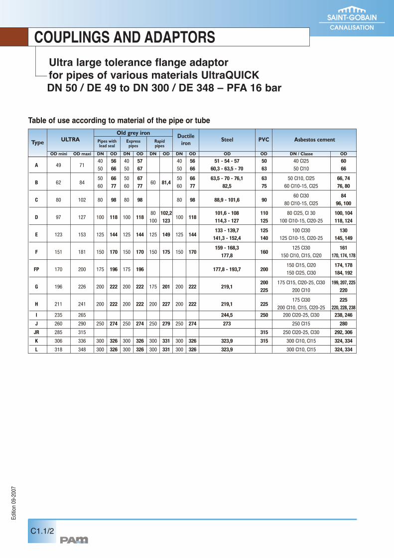
Ultra large tolerance flange adaptorfor pipes of various materials UltraQUICKDN 50 / DE 49 to DN 300 / DE 348 – PFA 16 bar
Table of use according to material of the pipe or tube
ULTRAOld grey iron
OD mini OD maxi DN / Classe ODODODDN
PVC Asbestos cement
40 56 40 57 40 56 51 - 54 - 57 50 40 Cl25 60A 49 71
50 66 50 67 50 66 60,3 - 63,5 - 70 63 50 Cl10 66
50 66 50 67 50 66 63,5 - 70 - 76,1 63 50 Cl10, Cl25 66, 74B 62 84
60 77 60 7760 81,4
60 77 82,5 75 60 Cl10-15, Cl25 76, 80
60 Cl30 84C 80 102 80 98 80 98 80 98 88,9 - 101,6 90
80 Cl10-15, Cl25 96, 100
80 102,2 101,6 - 108 110 80 Cl25, Cl 30 100, 104D 97 127 100 118 100 118
100 123100 118
114,3 - 127 125 100 Cl10-15, Cl20-25 118, 124
133 - 139,7 125 100 Cl30 130E 123 153 125 144 125 144 125 149 125 144
141,3 - 152,4 140 125 Cl10-15, Cl20-25 145, 149
159 - 168,3 125 Cl30 161F 151 181 150 170 150 170 150 175 150 170
177,8160
150 Cl10, Cl15, Cl20 170, 174, 178
150 Cl15, Cl20 174, 178FP 170 200 175 196 175 196 177,8 - 193,7 200
150 Cl25, Cl30 184, 192
200 175 Cl15, Cl20-25, Cl30 199, 207, 225G 196 226 200 222 200 222 175 201 200 222 219,1
225 200 Cl10 220
175 Cl30 225H 211 241 200 222 200 222 200 227 200 222 219,1 225
200 Cl10, Cl15, Cl20-25 220, 228, 238I 235 265 244,5 250 200 Cl20-25, Cl30 238, 246
J 260 290 250 274 250 274 250 279 250 274 273 250 Cl15 280
JR 285 315 315 250 Cl20-25, Cl30 292, 306
K 306 336 300 326 300 326 300 331 300 326 323,9 315 300 Cl10, Cl15 324, 334
L 318 348 300 326 300 326 300 331 300 326 323,9 300 Cl10, Cl15 324, 334
OD
SteelDuctileironRapid
pipesExpresspipes
Pipes withlead seal
ODDNODDNODDN
Type
C1.2/1
COUPLINGS AND ADAPTORS
FlangeDN
mm
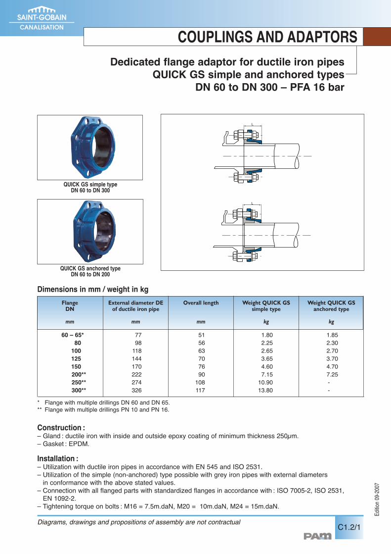
60 – 65* 77 51 1.80 1.8580 98 56 2.25 2.30100 118 63 2.65 2.70125 144 70 3.65 3.70150 170 76 4.60 4.70200** 222 90 7.15 7.25250** 274 108 10.90 -300** 326 117 13.80 -
Dedicated flange adaptor for ductile iron pipesQUICK GS simple and anchored types
DN 60 to DN 300 – PFA 16 bar
Construction :– Gland : ductile iron with inside and outside epoxy coating of minimum thickness 250µm.– Gasket : EPDM.
Installation :– Utilization with ductile iron pipes in accordance with EN 545 and ISO 2531.– Utilization of the simple (non-anchored) type possible with grey iron pipes with external diametersin conformance with the above stated values.
– Connection with all flanged parts with standardized flanges in accordance with : ISO 7005-2, ISO 2531,EN 1092-2.
– Tightening torque on bolts : M16 = 7.5m.daN, M20 = 10m.daN, M24 = 15m.daN.
Dimensions in mm / weight in kgExternal diameter DEof ductile iron pipe
mm
Overall length
mm
Weight QUICK GSsimple type
kg
Weight QUICK GSanchored type
kg
QUICK GS simple typeDN 60 to DN 300
QUICK GS anchored typeDN 60 to DN 200
* Flange with multiple drillings DN 60 and DN 65.** Flange with multiple drillings PN 10 and PN 16.
Diagrams, drawings and propositions of assembly are not contractual
Edition0
9-2007
COUPLINGS AND ADAPTORS
C1.2/2 Diagrams, drawings and propositions of assembly are not contractual
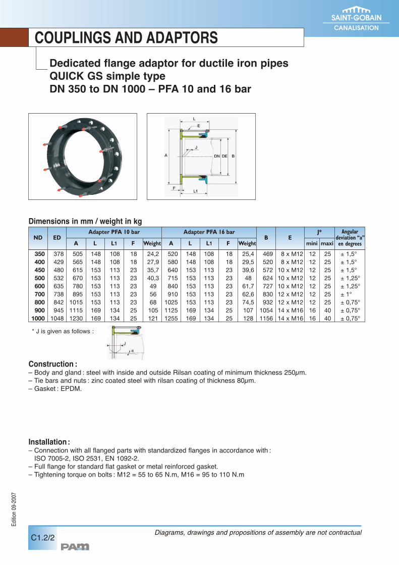
Construction :– Body and gland : steel with inside and outside Rilsan coating of minimum thickness 250µm.– Tie bars and nuts : zinc coated steel with rilsan coating of thickness 80µm.– Gasket : EPDM.
Installation:– Connection with all flanged parts with standardized flanges in accordance with :ISO 7005-2, ISO 2531, EN 1092-2.
– Full flange for standard flat gasket or metal reinforced gasket.– Tightening torque on bolts : M12 = 55 to 65 N.m, M16 = 95 to 110 N.m
Dedicated flange adaptor for ductile iron pipesQUICK GS simple typeDN 350 to DN 1000 – PFA 10 and 16 bar
Edition0
9-2007
Dimensions in mm / weight in kgND ED
Adapter PFA 10 bar Adapter PFA 16 barB E
J* Angulardeviation “a”en degreesA L L1 F Weight A L L1 F mini maxiWeight
350 378 505 148 108 18 24,2 520 148 108 18 25,4 469 8 x M12 12 25 ± 1,5°400 429 565 148 108 18 27,9 580 148 108 18 29,5 520 8 x M12 12 25 ± 1,5°450 480 615 153 113 23 35,7 640 153 113 23 39,6 572 10 x M12 12 25 ± 1,5°500 532 670 153 113 23 40,3 715 153 113 23 48 624 10 x M12 12 25 ± 1,25°600 635 780 153 113 23 49 840 153 113 23 61,7 727 10 x M12 12 25 ± 1,25°700 738 895 153 113 23 56 910 153 113 23 62,6 830 12 x M12 12 25 ± 1°800 842 1015 153 113 23 68 1025 153 113 23 74,5 932 12 x M12 12 25 ± 0,75°900 945 1115 169 134 25 105 1125 169 134 25 107 1054 14 x M16 16 40 ± 0,75°
1000 1048 1230 169 134 25 121 1255 169 134 25 128 1156 14 x M16 16 40 ± 0,75°
* J is given as follows :
C1.3/1
FlangeDN
mm
40 40 50 1.2 1.340 and 50* 50 52 1.5 1.6
50 63 54 1.8 1.960 and 65* 63 54 2.0 2.160 and 65* 75 58 2.3 2.4
80 90 62 2.6 2.8100 110 68 3.2 3.4125 125 73 4.1 4.3125 140 76 4.1 4.3150 160 82 5.4 5.7200** 200 91 7.9 8.2200** 225 93 7.3 7.7
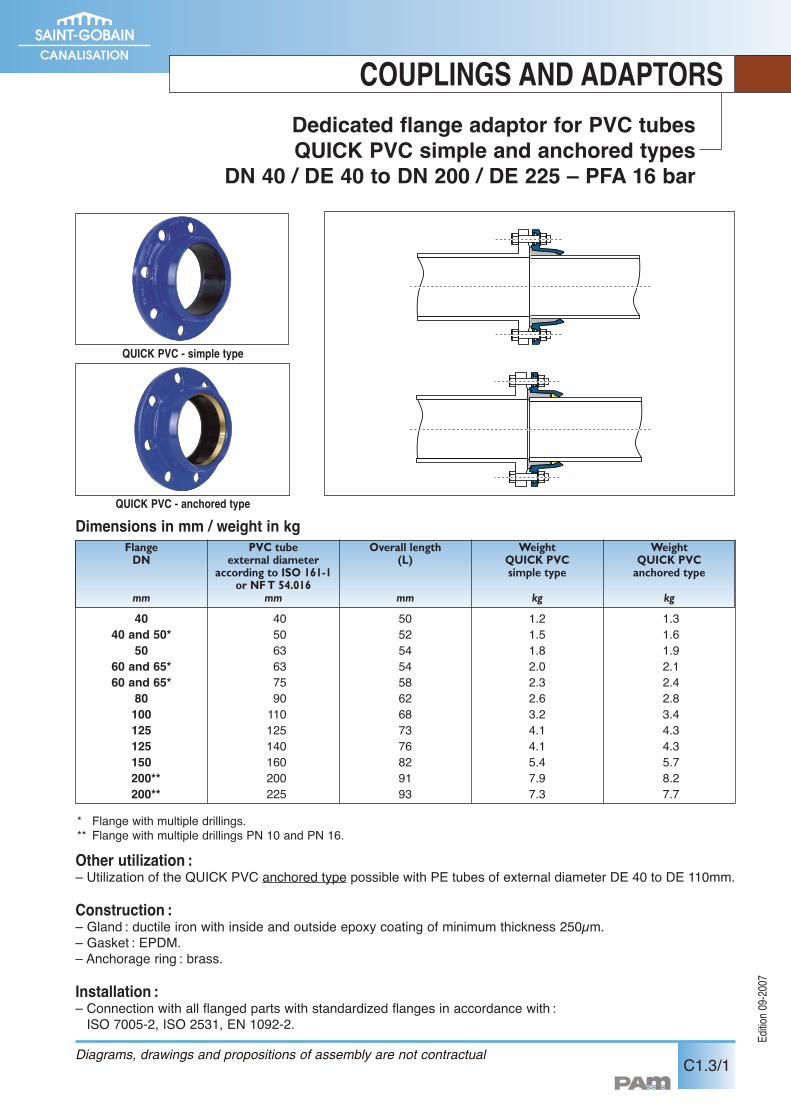
Dedicated flange adaptor for PVC tubesQUICK PVC simple and anchored types
DN 40 / DE 40 to DN 200 / DE 225 – PFA 16 bar
COUPLINGS AND ADAPTORS
Other utilization :– Utilization of the QUICK PVC anchored type possible with PE tubes of external diameter DE 40 to DE 110mm.
Construction :– Gland : ductile iron with inside and outside epoxy coating of minimum thickness 250µm.– Gasket : EPDM.– Anchorage ring : brass.
Installation :– Connection with all flanged parts with standardized flanges in accordance with :ISO 7005-2, ISO 2531, EN 1092-2.
Dimensions in mm / weight in kgPVC tube
external diameteraccording to ISO 161-1
or NFT 54.016mm
Overall length(L)
mm
WeightQUICK PVCsimple type
kg
WeightQUICK PVCanchored type
kg
QUICK PVC - simple type
QUICK PVC - anchored type
* Flange with multiple drillings.** Flange with multiple drillings PN 10 and PN 16.
Diagrams, drawings and propositions of assembly are not contractual
Edition0
9-2007
Edition0
9-2007
C1.4/1
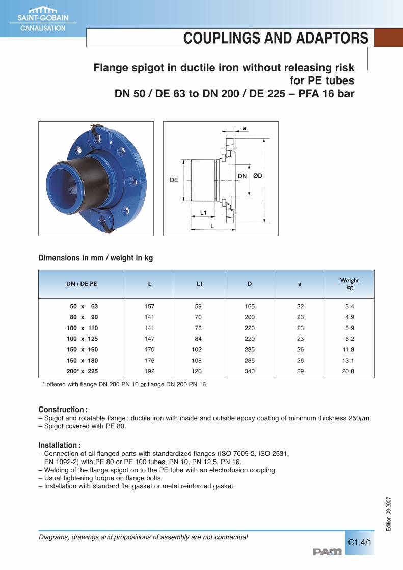
Flange spigot in ductile iron without releasing riskfor PE tubes
DN 50 / DE 63 to DN 200 / DE 225 – PFA 16 bar
COUPLINGS AND ADAPTORS
Construction :– Spigot and rotatable flange : ductile iron with inside and outside epoxy coating of minimum thickness 250µm.– Spigot covered with PE 80.
Installation :– Connection of all flanged parts with standardized flanges (ISO 7005-2, ISO 2531,EN 1092-2) with PE 80 or PE 100 tubes, PN 10, PN 12.5, PN 16.
– Welding of the flange spigot on to the PE tube with an electrofusion coupling.– Usual tightening torque on flange bolts.– Installation with standard flat gasket or metal reinforced gasket.
DN / DE PE
50 x 6380 x 90100 x 110100 x 125150 x 160150 x 180200* x 225
157141141147170176192
59707884102108120
22232323262629
165200220220285285340
3.44.95.96.211.813.120.8
L L1 D a Weightkg
Dimensions in mm / weight in kg
Diagrams, drawings and propositions of assembly are not contractual
* offered with flange DN 200 PN 10 or flange DN 200 PN 16
Edition0
9-2007
C2.1/1
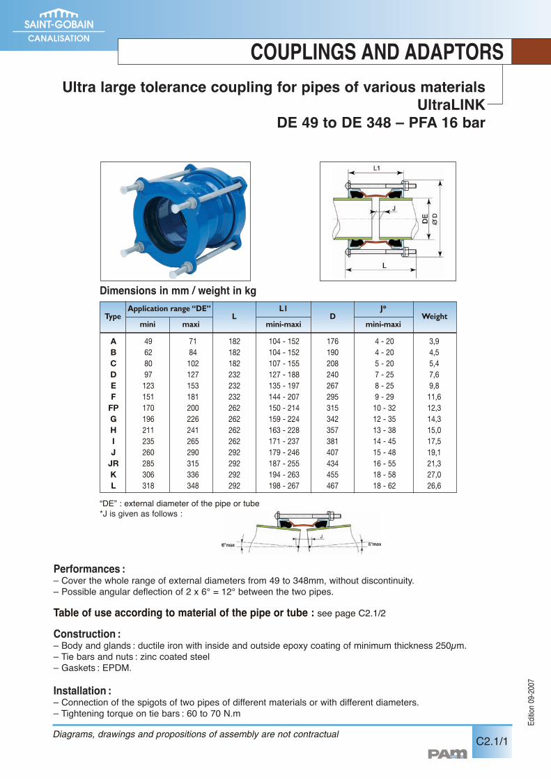
Performances :– Cover the whole range of external diameters from 49 to 348mm, without discontinuity.– Possible angular deflection of 2 x 6° = 12° between the two pipes.
Table of use according to material of the pipe or tube : see page C2.1/2Construction :– Body and glands : ductile iron with inside and outside epoxy coating of minimum thickness 250µm.– Tie bars and nuts : zinc coated steel– Gaskets : EPDM.
Installation :– Connection of the spigots of two pipes of different materials or with different diameters.– Tightening torque on tie bars : 60 to 70 N.m
COUPLINGS AND ADAPTORSUltra large tolerance coupling for pipes of various materials
UltraLINKDE 49 to DE 348 – PFA 16 bar
Diagrams, drawings and propositions of assembly are not contractual
Dimensions in mm / weight in kg
A 49 71 182 104 - 152 176 4 - 20 3,9B 62 84 182 104 - 152 190 4 - 20 4,5C 80 102 182 107 - 155 208 5 - 20 5,4D 97 127 232 127 - 188 240 7 - 25 7,6E 123 153 232 135 - 197 267 8 - 25 9,8F 151 181 232 144 - 207 295 9 - 29 11,6
FP 170 200 262 150 - 214 315 10 - 32 12,3G 196 226 262 159 - 224 342 12 - 35 14,3H 211 241 262 163 - 228 357 13 - 38 15,0I 235 265 262 171 - 237 381 14 - 45 17,5J 260 290 292 179 - 246 407 15 - 48 19,1
JR 285 315 292 187 - 255 434 16 - 55 21,3K 306 336 292 194 - 263 455 18 - 58 27,0L 318 348 292 198 - 267 467 18 - 62 26,6
TypeApplication range “DE” L1
mini maxi mini-maxi mini-maxi
J*WeightL D
“DE” : external diameter of the pipe or tube*J is given as follows :
Edition0
9-2007
COUPLINGS AND ADAPTORS
C2.1/2
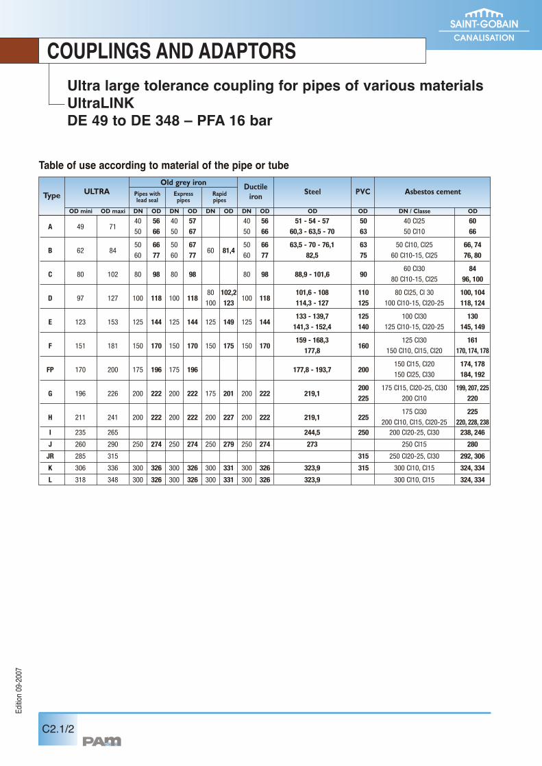
Ultra large tolerance coupling for pipes of various materialsUltraLINKDE 49 to DE 348 – PFA 16 bar
Table of use according to material of the pipe or tube
ULTRAOld grey iron
OD mini OD maxi DN / Classe ODODODDN
PVC Asbestos cement
40 56 40 57 40 56 51 - 54 - 57 50 40 Cl25 60A 49 71
50 66 50 67 50 66 60,3 - 63,5 - 70 63 50 Cl10 66
50 66 50 67 50 66 63,5 - 70 - 76,1 63 50 Cl10, Cl25 66, 74B 62 84
60 77 60 7760 81,4
60 77 82,5 75 60 Cl10-15, Cl25 76, 80
60 Cl30 84C 80 102 80 98 80 98 80 98 88,9 - 101,6 90
80 Cl10-15, Cl25 96, 100
80 102,2 101,6 - 108 110 80 Cl25, Cl 30 100, 104D 97 127 100 118 100 118
100 123100 118
114,3 - 127 125 100 Cl10-15, Cl20-25 118, 124
133 - 139,7 125 100 Cl30 130E 123 153 125 144 125 144 125 149 125 144
141,3 - 152,4 140 125 Cl10-15, Cl20-25 145, 149
159 - 168,3 125 Cl30 161F 151 181 150 170 150 170 150 175 150 170
177,8160
150 Cl10, Cl15, Cl20 170, 174, 178
150 Cl15, Cl20 174, 178FP 170 200 175 196 175 196 177,8 - 193,7 200
150 Cl25, Cl30 184, 192
200 175 Cl15, Cl20-25, Cl30 199, 207, 225G 196 226 200 222 200 222 175 201 200 222 219,1
225 200 Cl10 220
175 Cl30 225H 211 241 200 222 200 222 200 227 200 222 219,1 225
200 Cl10, Cl15, Cl20-25 220, 228, 238I 235 265 244,5 250 200 Cl20-25, Cl30 238, 246
J 260 290 250 274 250 274 250 279 250 274 273 250 Cl15 280
JR 285 315 315 250 Cl20-25, Cl30 292, 306
K 306 336 300 326 300 326 300 331 300 326 323,9 315 300 Cl10, Cl15 324, 334
L 318 348 300 326 300 326 300 331 300 326 323,9 300 Cl10, Cl15 324, 334
OD
SteelDuctileironRapid
pipesExpresspipes
Pipes withlead seal
ODDNODDNODDN
Type
Edition0
9-2007
C2.2/1
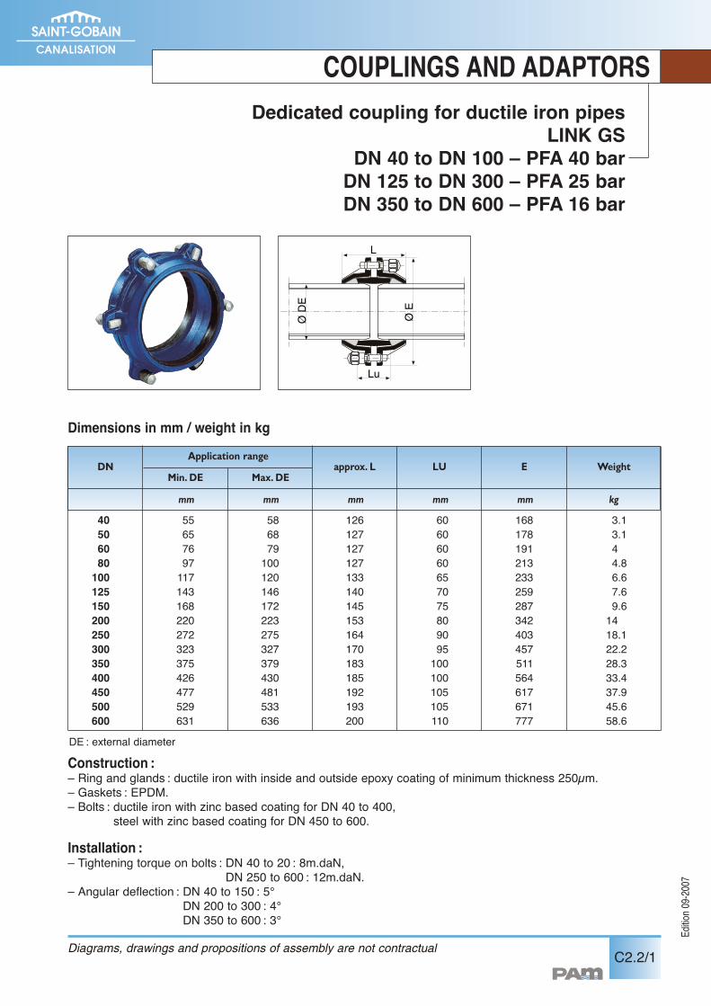
Dedicated coupling for ductile iron pipesLINK GS
DN 40 to DN 100 – PFA 40 barDN 125 to DN 300 – PFA 25 barDN 350 to DN 600 – PFA 16 bar
COUPLINGS AND ADAPTORS
Construction :– Ring and glands : ductile iron with inside and outside epoxy coating of minimum thickness 250µm.– Gaskets : EPDM.– Bolts : ductile iron with zinc based coating for DN 40 to 400,
steel with zinc based coating for DN 450 to 600.
Installation :– Tightening torque on bolts : DN 40 to 20 : 8m.daN,
DN 250 to 600 : 12m.daN.– Angular deflection : DN 40 to 150 : 5°
DN 200 to 300 : 4°DN 350 to 600 : 3°
Dimensions in mm / weight in kgØ
E
ØD
E
Lu
L
approx. L WeightLU EDNApplication range
Min. DE Max. DE
40 55 58 126 60 168 3.150 65 68 127 60 178 3.160 76 79 127 60 191 480 97 100 127 60 213 4.8100 117 120 133 65 233 6.6125 143 146 140 70 259 7.6150 168 172 145 75 287 9.6200 220 223 153 80 342 14250 272 275 164 90 403 18.1300 323 327 170 95 457 22.2350 375 379 183 100 511 28.3400 426 430 185 100 564 33.4450 477 481 192 105 617 37.9500 529 533 193 105 671 45.6600 631 636 200 110 777 58.6
mm mm mm mm mm kg
Diagrams, drawings and propositions of assembly are not contractual
DE : external diameter
COUPLINGS AND ADAPTORS
C2.2/2 Diagrams, drawings and propositions of assembly are not contractual
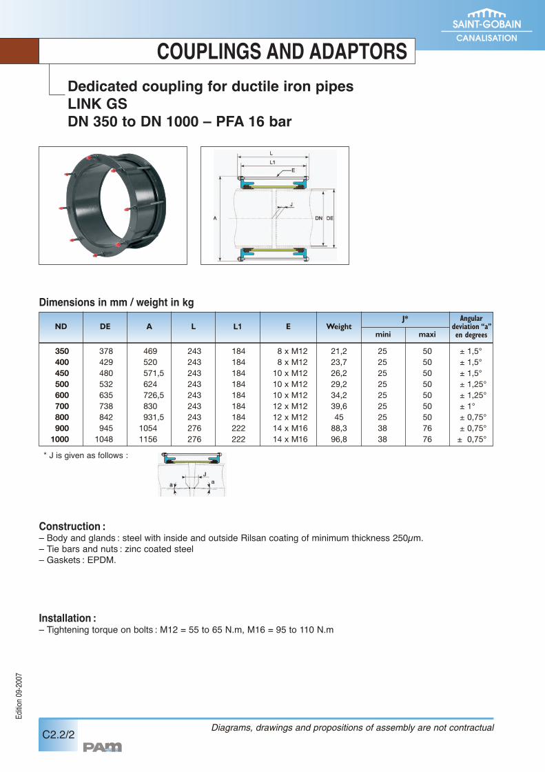
Construction :– Body and glands : steel with inside and outside Rilsan coating of minimum thickness 250µm.– Tie bars and nuts : zinc coated steel– Gaskets : EPDM.
Installation :– Tightening torque on bolts : M12 = 55 to 65 N.m, M16 = 95 to 110 N.m
Dedicated coupling for ductile iron pipesLINK GSDN 350 to DN 1000 – PFA 16 bar
Edition0
9-2007
Dimensions in mm / weight in kg
* J is given as follows :
350 378 469 243 184 8 x M12 21,2 25 50 ± 1,5°400 429 520 243 184 8 x M12 23,7 25 50 ± 1,5°450 480 571,5 243 184 10 x M12 26,2 25 50 ± 1,5°500 532 624 243 184 10 x M12 29,2 25 50 ± 1,25°600 635 726,5 243 184 10 x M12 34,2 25 50 ± 1,25°700 738 830 243 184 12 x M12 39,6 25 50 ± 1°800 842 931,5 243 184 12 x M12 45 25 50 ± 0,75°900 945 1054 276 222 14 x M16 88,3 38 76 ± 0,75°
1000 1048 1156 276 222 14 x M16 96,8 38 76 ± 0,75°
ND DE A L L1 Emini
J*
maxi
Angulardeviation “a”en degrees
Weight
Edition0
9-2007
C2.3/1
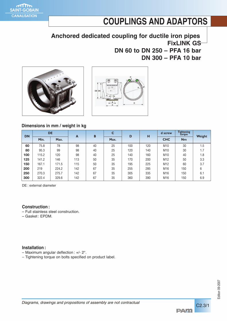
Construction :– Full stainless steel construction.– Gasket : EPDM.
Installation :– Maximum angular deflection : +/- 2°.– Tightening torque on bolts specified on product label.
COUPLINGS AND ADAPTORSAnchored dedicated coupling for ductile iron pipes
FixLINK GSDN 60 to DN 250 – PFA 16 bar
DN 300 – PFA 10 bar
Diagrams, drawings and propositions of assembly are not contractual
60 75.8 78 98 40 25 100 120 M10 30 1.580 95.3 99 98 40 25 120 140 M10 30 1.7
100 115.2 120 98 40 25 140 160 M10 40 1.8125 141.2 146 113 50 35 170 200 M12 50 3.3150 167.1 171.5 115 50 35 195 225 M12 60 3.7200 219 224.2 142 67 35 255 285 M16 150 6250 270.3 275.7 142 67 35 305 335 M16 150 6.1300 322.4 329.6 142 67 35 360 390 M16 150 6.9
DNDE C
DMin.
HMax. Max. NmCHC
d screw Tighteningtorque
WeightA B
Dimensions in mm / weight in kg
DE : external diameter
Edition0
9-2007
C2.4/1
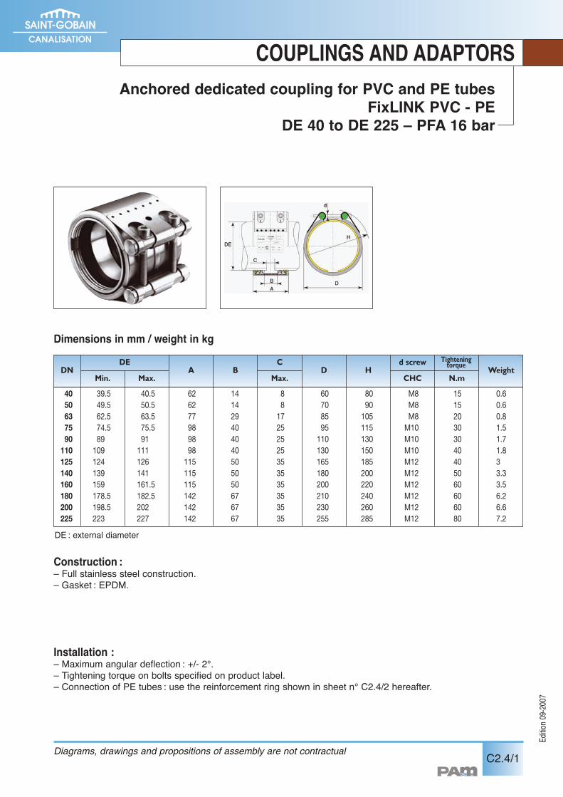
Anchored dedicated coupling for PVC and PE tubesFixLINK PVC - PE
DE 40 to DE 225 – PFA 16 bar
COUPLINGS AND ADAPTORS
Construction :– Full stainless steel construction.– Gasket : EPDM.
Installation :– Maximum angular deflection : +/- 2°.– Tightening torque on bolts specified on product label.– Connection of PE tubes : use the reinforcement ring shown in sheet n° C2.4/2 hereafter.
Dimensions in mm / weight in kg
Diagrams, drawings and propositions of assembly are not contractual
40 39.5 40.5 62 14 8 60 80 M8 15 0.650 49.5 50.5 62 14 8 70 90 M8 15 0.663 62.5 63.5 77 29 17 85 105 M8 20 0.875 74.5 75.5 98 40 25 95 115 M10 30 1.590 89 91 98 40 25 110 130 M10 30 1.7
110 109 111 98 40 25 130 150 M10 40 1.8125 124 126 115 50 35 165 185 M12 40 3140 139 141 115 50 35 180 200 M12 50 3.3160 159 161.5 115 50 35 200 220 M12 60 3.5180 178.5 182.5 142 67 35 210 240 M12 60 6.2200 198.5 202 142 67 35 230 260 M12 60 6.6225 223 227 142 67 35 255 285 M12 80 7.2
DNDE C
DMin.
HMax. Max. N.mCHC
d screw Tighteningtorque
WeightA B
DE : external diameter
COUPLINGS AND ADAPTORS
C2.4/2 Diagrams, drawings and propositions of assembly are not contractual
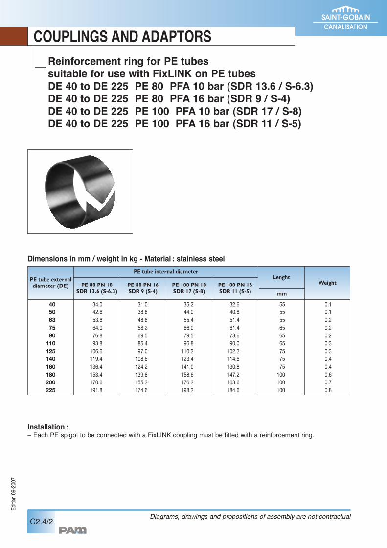
Installation :– Each PE spigot to be connected with a FixLINK coupling must be fitted with a reinforcement ring.
Reinforcement ring for PE tubessuitable for use with FixLINK on PE tubesDE 40 to DE 225 PE 80 PFA 10 bar (SDR 13.6 / S-6.3)DE 40 to DE 225 PE 80 PFA 16 bar (SDR 9 / S-4)DE 40 to DE 225 PE 100 PFA 10 bar (SDR 17 / S-8)DE 40 to DE 225 PE 100 PFA 16 bar (SDR 11 / S-5)
Edition0
9-2007
Dimensions in mm / weight in kg - Material : stainless steel
40 34.0 31.0 35.2 32.6 55 0.150 42.6 38.8 44.0 40.8 55 0.163 53.6 48.8 55.4 51.4 55 0.275 64.0 58.2 66.0 61.4 65 0.290 76.8 69.5 79.5 73.6 65 0.2
110 93.8 85.4 96.8 90.0 65 0.3125 106.6 97.0 110.2 102.2 75 0.3140 119.4 108.6 123.4 114.6 75 0.4160 136.4 124.2 141.0 130.8 75 0.4180 153.4 139.8 158.6 147.2 100 0.6200 170.6 155.2 176.2 163.6 100 0.7225 191.8 174.6 198.2 184.6 100 0.8
PE tube externaldiameter (DE)
PE tube internal diameter
PE 80 PN 10SDR 13.6 (S-6.3)
PE 80 PN 16SDR 9 (S-4)
PE 100 PN 10SDR 17 (S-8)
PE 100 PN 16SDR 11 (S-5)
Lenght
mm
Weight
Edition0
9-2007
C3.1/1
COUPLINGS AND ADAPTORS
2622.5201715.513.512.510.59.5986.565.54.543.532.52.5
323130292826252322.521.52020191716.5161513.513121110.59.598.58
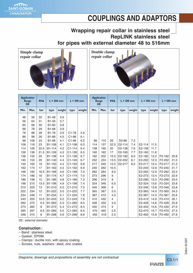
Wrapping repair collar in stainless steelRepLINK stainless steel
for pipes with external diameter 48 to 516mm
Construction :– Band : stainless steel.– Gasket : EPDM.– Clamps : ductile iron, with epoxy coating.– Screws, nuts, washers : steel, zinc coated.
ApplicationRangeDE
L = 200 mm L = 300 mmPFA
Min. Max. bar type weight type weight
48566068788898108114126138140150162168174186198210222234243260273285298
566468788898108118126138150153162174182186198210223234246255272285297310
B1-48B1-56B1-60B1-68B1-78B1-88B1-98B1-108B1-114B1-126B1-138B1-140B1-150B1-162B1-168B1-174B1-186B1-198B1-210B1-222B1-234B1-243B1-260B1-273B1-285B1-298
3.63.73.83.83.94.04.14.14.24.34.44.44.44.54.64.74.84.95.05.05.15.25.35.45.55.6
C1-78C1-88C1-98C1-108C1-114C1-126C1-138C1-140C1-150C1-162C1-168C1-174C1-186C1-198C1-210C1-222C1-234C1-243C1-260C1-273C1-285C1-298
5.96.16.26.36.46.56.76.76.86.97.07.07.37.47.57.77.87.98.08.38.48.6
ApplicationRangeDE
L = 200 mm L = 300 mmPFA
Min. Max. bar type weight type weight
88114138160182202217240262273296324346365387410428450470492
110137160182202224240262284296319346368387410432450474492516
D2-88D2-114D2-138D2-160D2-182D2-202D2-217
7.27.47.67.78.08.18.2
E2-114E2-138E2-160E2-182E2-202E2-217E2-240E2-262E2-273E2-296E2-324E2-346E2-365E2-387E2-410E2-428E2-450E2-470E2-492
11.511.711.812.212.312.412.812.913.413.313.613.814.014.314.614.815.615.715.8
L = 500 mm
type weight
F2-182F2-202F2-217F2-240F2-262F2-273F2-296F2-324F2-346F2-365F2-387F2-410F2-428F2-450F2-470F2-492
20.821.021.221.722.322.623.023.823.824.325.626.125.827.027.327.8
Simple clamprepair collar
Double clamprepair collar
Diagrams, drawings and propositions of assembly are not contractual
DE : external diameter
Edition0
9-2007
COUPLINGS AND ADAPTORS
C3.1/2 Diagrams, drawings and propositions of assembly are not contractual
Lead seal
Iron
Grey Ductile
EXPRESS
PVC-U Steel
DE Type DE Type
DN
40506080100125150175200250300350400450
56667798118144170196222274326378429480
57677798118144170196222274326378429480
48.3545760.3707376.188.9108114.3133139.7141.3159168.3177.8193.7219.1244.5273323.9355.6406.4
B1-48 / B1-56B1-60 / B1-68B1-68 / B1-78B1-88 / B1-98
B1-114B1-138B1-162
B1-186 / B1-198B1-210 / B1-222B1-260 / B1-273
E2-324E2-365E2-410E2-470
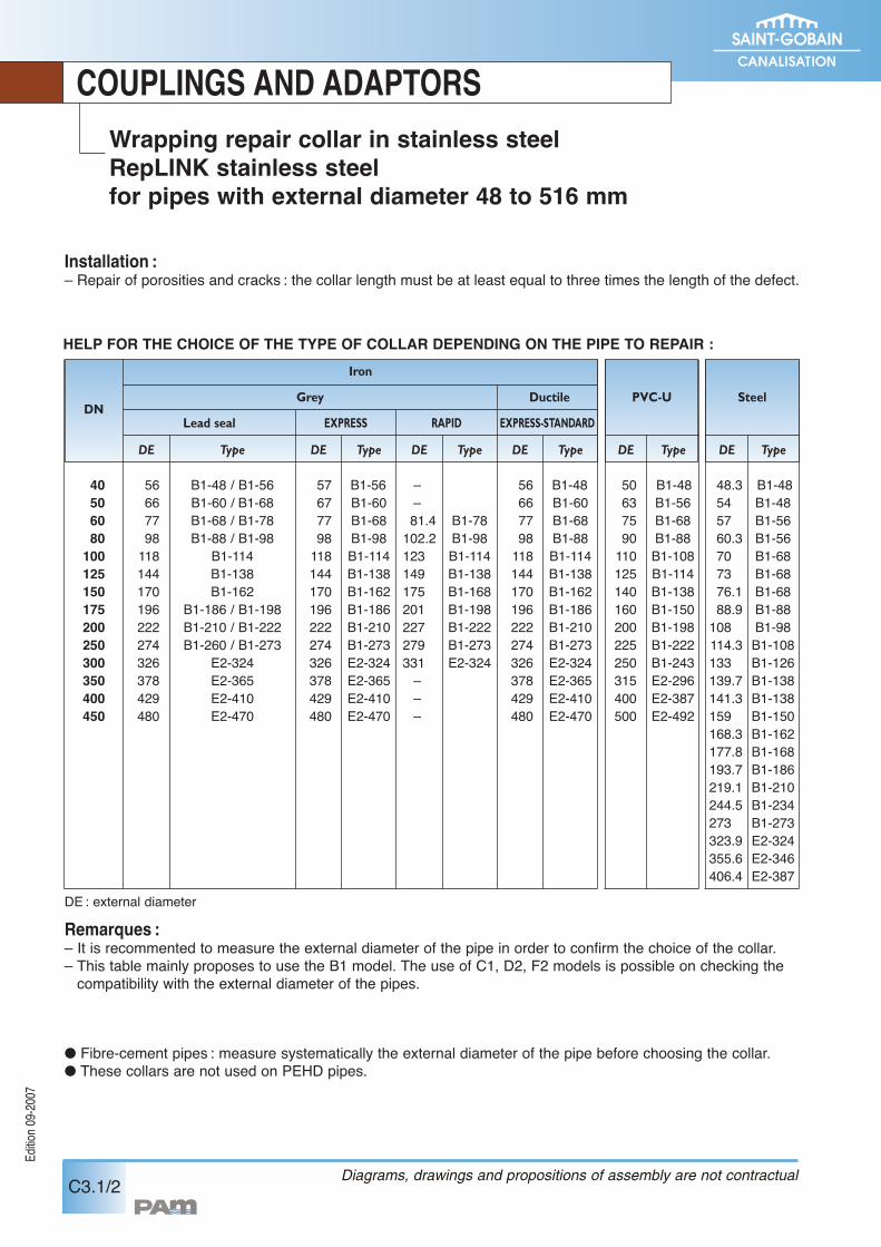
Installation :– Repair of porosities and cracks : the collar length must be at least equal to three times the length of the defect.
HELP FOR THE CHOICE OF THE TYPE OF COLLAR DEPENDING ON THE PIPE TO REPAIR :
Remarques :– It is recommented to measure the external diameter of the pipe in order to confirm the choice of the collar.– This table mainly proposes to use the B1 model. The use of C1, D2, F2 models is possible on checking thecompatibility with the external diameter of the pipes.
� Fibre-cement pipes : measure systematically the external diameter of the pipe before choosing the collar.� These collars are not used on PEHD pipes.
B1-56B1-60B1-68B1-98B1-114B1-138B1-162B1-186B1-210B1-273E2-324E2-365E2-410E2-470
DE Type
––81.4102.2123149175201227279331–––
B1-78B1-98B1-114B1-138B1-168B1-198B1-222B1-273E2-324
DE Type
56667798118144170196222274326378429480
B1-48B1-60B1-68B1-88B1-114B1-138B1-162B1-186B1-210B1-273E2-324E2-365E2-410E2-470
DE Type
50637590110125140160200225250315400500
B1-48B1-56B1-68B1-88B1-108B1-114B1-138B1-150B1-198B1-222B1-243E2-296E2-387E2-492
DE Type
B1-48B1-48B1-56B1-56B1-68B1-68B1-68B1-88B1-98B1-108B1-126B1-138B1-138B1-150B1-162B1-168B1-186B1-210B1-234B1-273E2-324E2-346E2-387
RAPID EXPRESS-STANDARD
Wrapping repair collar in stainless steelRepLINK stainless steelfor pipes with external diameter 48 to 516 mm
DE : external diameter
Edition0
9-2007
C3.2/1
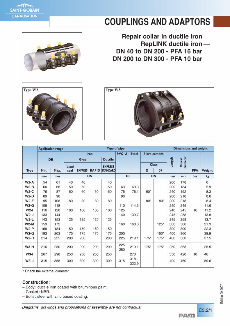
Repair collar in ductile ironRepLINK ductile iron
DN 40 to DN 200 - PFA 16 barDN 200 to DN 300 - PFA 10 bar
COUPLINGS AND ADAPTORS
W2-A 54 61 40 40 40 200 178 6W2-B 60 68 50 50 50 63 60.3 200 184 5.9W2-C 76 87 60 60 60 60 75 76.1 60* 240 192 8.3W2-D 89 98 90 200 218 8.6W2-F 95 108 80 80 80 80 80* 80* 200 218 8.4W2-G 108 118 110 114.3 240 245 11.6W2-I 116 128 100 100 100 100 125 240 245 16 11.2W2-J 133 144 140 139.7 245 258 13.8W2-L 142 153 125 125 125 125 245 258 13.7W2-M 159 172 160 168.3 125* 300 300 21.3W2-P 168 184 150 150 150 150 300 300 22.3W2-Q 193 203 175 175 175 175 200 150* 400 360 39.9W2-R 214 225 200 200 200 225 219.1 175* 175* 400 360 37.5
W3-H 216 250 200 200 200 200 225 219.1 175* 175* 250 365 25.5250W3-I 267 298 250 250 250 250 273 350 420 10 46W3-J 315 358 300 300 300 300 315 318 400 460 59.6323.9
Construction :– Body : ductile iron coated with bituminous paint.– Gasket : NBR.– Bolts : steel with zinc based coating.
Type W2 Type W3
Application range
Leadseal
Iron
Grey Ductile
EXPRESS RAPIDEXPRESSSTANDARD
PVC-U Steel Fibre-cement
25 30 PFA Weight
Overall
diam
eter
Type
DN DNDE
Class
Min. Max.LengthDE
Type of pipe
mm mm mm mm bar kg
* Check the external diameter.
Dimensions and weight
Diagrams, drawings and propositions of assembly are not contractual
Edition0
9-2007
C4.1/1
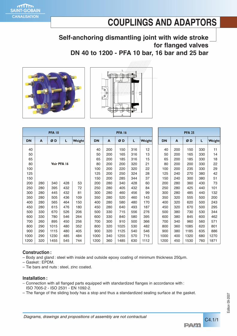
COUPLINGS AND ADAPTORSSelf-anchoring dismantling joint with wide stroke
for flanged valvesDN 40 to 1200 - PFA 10 bar, 16 bar and 25 bar
L
flD
DN
A
Construction :– Body and gland : steel with inside and outside epoxy coating of minimum thickness 250µm.– Gasket : EPDM.– Tie bars and nuts : steel, zinc coated.
Installation :– Connection with all flanged parts equipped with standardized flanges in accordance with :ISO 7005-2 - ISO 2531 - EN 1092-2.
– The flange of the sliding body has a stop and thus a standardized sealing surface at the gasket.
Diagrams, drawings and propositions of assembly are not contractual
PFA 10
DN A Ø D L Weight
4050658010012515020025030035040045050060070080090010001200
3403954455055656156707808951015111512301455
428432432436464476526546450480480485545
537281109150180206264256352405484744
280280280280280280330330260290290290320
Voir PFA 16
PFA 16
DN A Ø D L Weight
4050658010012515020025030035040045050060070080090010001200
1501651852002202502853404054605205806407158409101025112512551485
316316316320320324344428432456460480493556580500530540570630
121315212228376084991431701872763953664825467151112
200200200200200200200280280280280280280330330300320320340360
PFA 25
DN A Ø D L Weight
4050658010012515020025030035040045050060070080090010001200
1501651852002352703003604254855556206707308459601085118513201530
330330330330330380380430440440500500500530600560620635680760
111418222942517310113220024329534446257180188612701871
200200200200200240240280280280320320320380380340360380400450
Edition0
9-2007
C4.2/1
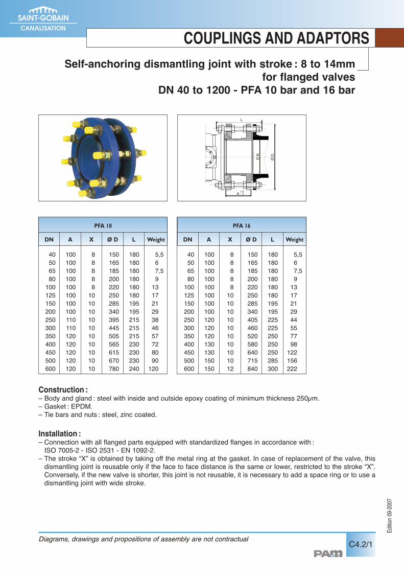
COUPLINGS AND ADAPTORSSelf-anchoring dismantling joint with stroke : 8 to 14mm
for flanged valvesDN 40 to 1200 - PFA 10 bar and 16 bar
������
�
����
�������� ��
��������
����
���
����
�������
�
����
L
Ø D
D N
A+ 0- x
PFA 10
DN A Ø D L Weight
40506580100125150200250300350400450500600
150165185200220250285340395445505565615670780
180180180180180180195195215215215230230230240
5,567,5913172129384657728090120
100100100100100100100100110110120120120120120
X
8888810101010101010101010
PFA 16
DN A Ø D L Weight
40506580100125150200250300350400450500600
150165185200220250285340405460520580640715840
180180180180180180195195225225250250250285300
5,567,591317212944557798122156222
100100100100100100100100120120120130130150150
X
8888810101010101010101012
Construction :– Body and gland : steel with inside and outside epoxy coating of minimum thickness 250µm.– Gasket : EPDM.– Tie bars and nuts : steel, zinc coated.
Installation :– Connection with all flanged parts equipped with standardized flanges in accordance with :ISO 7005-2 - ISO 2531 - EN 1092-2.
– The stroke “X” is obtained by taking off the metal ring at the gasket. In case of replacement of the valve, thisdismantling joint is reusable only if the face to face distance is the same or lower, restricted to the stroke “X”.Conversely, if the new valve is shorter, this joint is not reusable, it is necessary to add a space ring or to use adismantling joint with wide stroke.
Diagrams, drawings and propositions of assembly are not contractual