Embed Size (px)
Citation preview

Open JoistTM
Floor Trusses
FIELD INSTALLATION
GUIDE
Read carefully before installing Open Joist
This guide is a supplement to an engineered Floor Framing Plan created for a specific job. Details included in the Floor
Framing Plan take precedence over any other general Open Joist framing details contained in this guide.
IMPORTANT: Deviation from the engineered Floor Framing
Plan supplied for a specific job will result in material shortages, job delays and possible unsafe installations! Do not deviate from the plan without contacting your
Open Joist representative.
This guide is also available in Spanish.Esta guía también esta disponible en Español.
For more information, view our website on Open Joist at http://www.openjoist.com
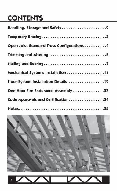
CONTENTSHandling, Storage and Safety . . . . . . . . . . . . . . . . . . . .2
Temporary Bracing . . . . . . . . . . . . . . . . . . . . . . . . . . . . .3
Open Joist Standard Truss Configurations . . . . . . . . . .4
Trimming and Altering . . . . . . . . . . . . . . . . . . . . . . . . . .5
Nailing and Bearing . . . . . . . . . . . . . . . . . . . . . . . . . . . .7
Mechanical Systems Installation . . . . . . . . . . . . . . . . .11
Floor System Installation Details . . . . . . . . . . . . . . . .12
One Hour Fire Endurance Assembly . . . . . . . . . . . . . .33
Code Approvals and Certification . . . . . . . . . . . . . . . .34
Notes . . . . . . . . . . . . . . . . . . . . . . . . . . . . . . . . . . . . . .35
1
HANDLING, STORAGE AND SAFETY
Handle Open Joist trusses upright and by the bottom chord. Handle trusses carefully to avoid damaging them.
Store trusses out of mud and water.
Open Joist floor trusses stored outdoors should be covered forprotection from weather.
In the interest of safety, bundles of Open Joist should remain bandeduntil ready for use. Care should be exercised when cutting bands on bundles.
Avoid excessive flat-wise bending of Open Joist trusses. Only useOpen Joist floor trusses for their intended purposes. Do not use trusses for ramps, ladders, etc.
Open Joist trusses are designed for floor framing and may onlybe used for roof framing if the roof pitch is 1/2 on 12 or less and trusses have been adequately sized.
Distribute piles of building materials (gypsum board, plywood, concreteblocks, etc.) in small bundles and over bearing supports. Do not overload Open Joist members. Do not stack materials on trusses that have not been properly supported, braced or sheathed to provide lateral support.
Do not walk on floor trusses that have not been properly supportedand braced.
For any questions about the correct use of Open Joist floor trusses,call Open Joist Technical Services at 800-584-5191.
2
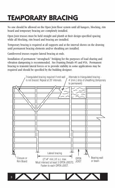
TEMPORARY BRACINGNo one should be allowed on the Open Joist floor system until all hangers, blocking, rim board and temporary bracing are completely installed.
Open Joist trusses must be held straight and plumb at their design-specified spacingwhile all blocking, rim board and bracing are installed.
Temporary bracing is required at all supports and at the interval shown on the drawinguntil permanent bracing elements and/or sheathing are installed.
Cantilevered trusses require lateral bracing at ends.
Installation of permanent “strongback” bridging for the purposes of load sharing andvibration dampening is recommended. See Framing Details #5 and #5A. Permanent bracing to transmit lateral forces or to provide stability in some applications may be required and should be specified by the building designer.
3
Closure or Rim Board
Lateral bracing
(2”x4” min.) 8’ o.c. max.Must intersect at least 3 OPEN JOISTS.
Fasten to each OPEN JOIST.
OPEN JOIST
Bearing wall or beam
Triangulated bracing required if end wall is not braced. Repeat at 20’ intervals.
Alternate to triangulated bracing - 4’ (min.) strip of sheathing (temporaryto permanent)
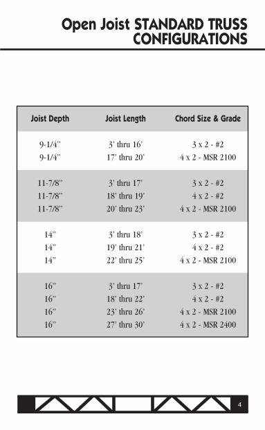
Open Joist STANDARD TRUSS CONFIGURATIONS
Joist Depth Joist Length Chord Size & Grade
9-1/4” 3’ thru 16’ 3 x 2 - #2
9-1/4” 17’ thru 20’ 4 x 2 - MSR 2100
11-7/8” 3’ thru 17’ 3 x 2 - #2
11-7/8” 18’ thru 19’ 4 x 2 - #2
11-7/8” 20’ thru 23’ 4 x 2 - MSR 2100
14” 3’ thru 18’ 3 x 2 - #2
14” 19’ thru 21’ 4 x 2 - #2
14” 22’ thru 25’ 4 x 2 - MSR 2100
16” 3’ thru 17’ 3 x 2 - #2
16” 18’ thru 22’ 4 x 2 - #2
16” 23’ thru 26’ 4 x 2 - MSR 2100
16” 27’ thru 30’ 4 x 2 - MSR 2400
4
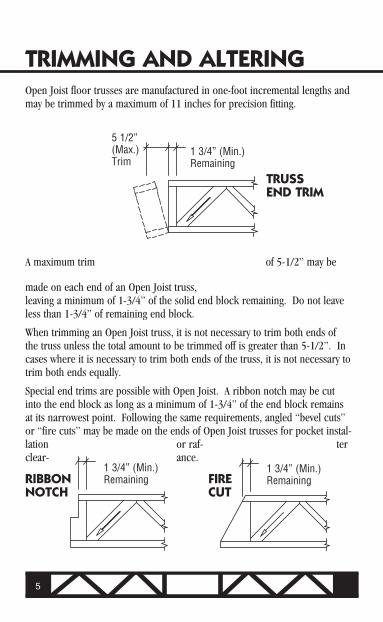
TRIMMING AND ALTERINGOpen Joist floor trusses are manufactured in one-foot incremental lengths and may be trimmed by a maximum of 11 inches for precision fitting.
A maximum trim of 5-1/2” may be
made on each end of an Open Joist truss,leaving a minimum of 1-3/4” of the solid end block remaining. Do not leave less than 1-3/4” of remaining end block.
When trimming an Open Joist truss, it is not necessary to trim both ends of the truss unless the total amount to be trimmed off is greater than 5-1/2”. In cases where it is necessary to trim both ends of the truss, it is not necessary to trim both ends equally.
Special end trims are possible with Open Joist. A ribbon notch may be cut into the end block as long as a minimum of 1-3/4” of the end block remains at its narrowest point. Following the same requirements, angled “bevel cuts” or “fire cuts” may be made on the ends of Open Joist trusses for pocket instal-lation or raf- ter clear- ance.
5
TRUSSEND TRIM
RIBBONNOTCH
FIRECUT
1 3/4” (Min.)Remaining
5 1/2” (Max.)Trim
1 3/4” (Min.)Remaining
1 3/4” (Min.)Remaining

THESE CONDITIONS ARE NOT PERMITTED
DETAIL NO. 18
6
Only the end blocks of Open Joist trusses may be cut according to the guide-lines stated. Top and bottom truss chords and truss webs may not be cut, drilled or notched. Altering these elements will alter the trusses’ structural integrity and may result in dangerous conditions. Cutting, drilling or notching chords and webs (other than normal end block trims as previously stated) without prior approval from Open Joist Engineering will result in the assumption of liability for floor system defects and responsibility for repair of such defects by the mechanic who performs unauthorized cutting or altering. Care should be taken during truss layout to allow for adequate mechanical clearances so that there will be no need to cut or notch trusses. Mechanicals subcontractors should be made aware of these cautions. If trusses have been cut, altered or installed incorrectly, contact Open Joist Engineering immediately at 800-584-5191.
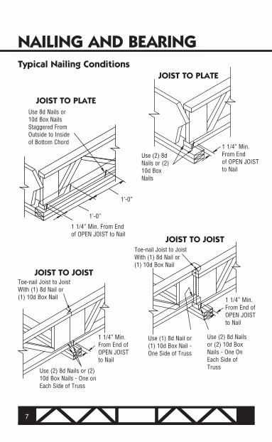
NAILING AND BEARINGTypical Nailing Conditions
7
JOIST TO JOIST
JOIST TO PLATE
Use 8d Nails or 10d Box Nails Staggered FromOutside to Inside of Bottom Chord
1 1/4” Min. From Endof OPEN JOIST to Nail
1’-0”
1’-0”
1 1/4” Min. From Endof OPEN JOIST to Nail
Toe-nail Joist to Joist With (1) 8d Nail or (1) 10d Box Nail
Use (2) 8d Nails or (2) 10d Box Nails - One on Each Side of Truss
1 1/4” Min. From End of OPEN JOIST to Nail
Use (1) 8d Nail or (1) 10d Box Nail - One Side of Truss
Use (2) 8d Nails or (2) 10d Box Nails - One On Each Side of Truss
JOIST TO JOIST
1 1/4” Min. From End of OPEN JOIST to Nail
Toe-nail Joist to Joist With (1) 8d Nail or (1) 10d Box Nail
JOIST TO PLATE
Use (2) 8d Nails or (2)10d Box Nails

RIM TO JOIST
RIM TO JOIST
Attach Rim Board to Side of OPEN JOIST With 8d Nails at 4” o.c. Into Top and Bottom Chords
8
Attach Rim Board to End of OPEN JOIST With (1) 8d Nail at Each Flange and (1) 8d Nail Centered at End Block
Nailing NotesCaution: When fastening Open Joist trusses, care should be taken to avoid splittingwooden truss members.
Hangers: Follow hanger manufacturers’ nailing instructions when installing Open Joisttrusses with hangers.
Gussets: Open Joist engineered drawings will specify nailing schedules for attachmentof gussets to trusses for cantilever and point load situations.
Strongback Bracing: When fastening 2X bracing perpendicular to and through OPENJOIST trusses, use the following attachments. When fastening to a vertical web or block, use (2) 3” nails fastened to the vertical member only. When fastening to a diagonal web, use (1) 3” nail into the web and (1) 3” nail into the bottom truss chord (see details 5 and 5A). Strongback bracing should be nailed in place before decking/sheathing is installed.
Decking/Sheathing: Follow APA recommendations for fastening sheathing to the top chordof Open Joist floor trusses and rim members.
Screws: Wood screws of sufficient strength may be substituted for nails when fasteningOpen Joist floor trusses.
Adhesives: Engineered drawings will specify adhesive requirements where needed forattachment of gussets, etc. Using adhesives in addition to fasteners when installing decking/sheathing will improve floor system performance.
NAILING AND BEARING CONTINUED
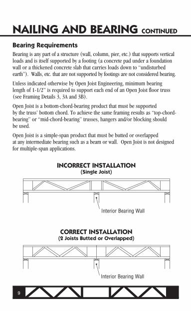
Bearing RequirementsBearing is any part of a structure (wall, column, pier, etc.) that supports verticalloads and is itself supported by a footing (a concrete pad under a foundation wall or a thickened concrete slab that carries loads down to “undisturbed earth”). Walls, etc. that are not supported by footings are not considered bearing.
Unless indicated otherwise by Open Joist Engineering, minimum bearinglength of 1-1/2” is required to support each end of an Open Joist floor truss (see Framing Details 3, 3A and 3B).
Open Joist is a bottom-chord-bearing product that must be supportedby the truss’ bottom chord. To achieve the same framing results as “top-chord-bearing” or “mid-chord-bearing” trusses, hangers and/or blocking should be used.
Open Joist is a simple-span product that must be butted or overlappedat any intermediate bearing such as a beam or wall. Open Joist is not designed for multiple-span applications.
9
INCORRECT INSTALLATION(Single Joist)
CORRECT INSTALLATION(2 Joists Butted or Overlapped)
Interior Bearing Wall
Interior Bearing Wall
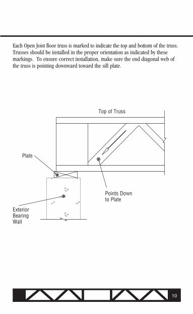
Each Open Joist floor truss is marked to indicate the top and bottom of the truss. Trusses should be installed in the proper orientation as indicated by these markings. To ensure correct installation, make sure the end diagonal web of the truss is pointing downward toward the sill plate.
Points Downto Plate
Plate
Top of Truss
ExteriorBearing Wall
10

Plumbing, electrical and HVAC systems can be installed around and through the open web area of Open Joist floor trusses as long as the truss chords and webs are not cut, notched or altered.
Cutting or notching chords and webs (other than normal end block trims)without prior approval from Open Joist Engineering will result in the assumption of liability for floor system defects and responsibility for the repair of such defects by the mechanic who performs the unauthorized cutting or altering. Care should be taken dur-ing truss layout to allow for adequate mechanical clearances so there will be no need to cut or notch trusses. Mechanicals sub-contractors should be made aware of these cautions.
Detail #17 below shows typical through-web clearances for mechanicals. In addition,Open Joist floor trusses feature a rectangular chase opening (size varies by truss size) located at the center of the truss.
MECHANICAL SYSTEMS INSTALLATION
11
MECHANICAL SERVICE CLEARANCE
DETAIL NO. 17
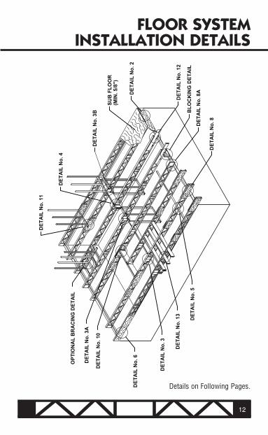
FLOOR SYSTEMINSTALLATION DETAILS
12
Details on Following Pages.
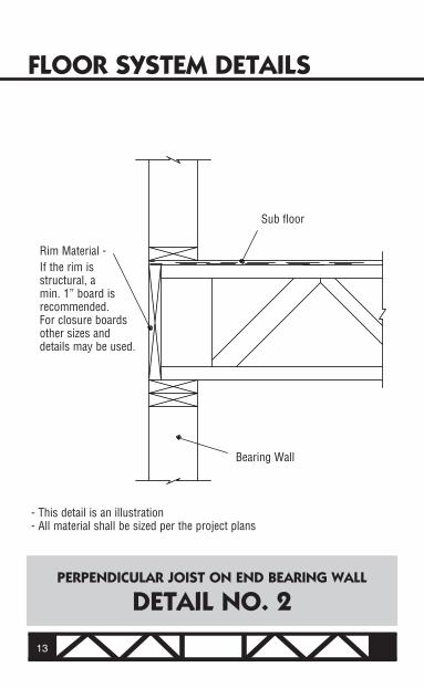
FLOOR SYSTEM DETAILS
Sub floor
Bearing Wall
PERPENDICULAR JOIST ON END BEARING WALL
DETAIL NO. 2
13
Rim Material -If the rim is structural, a min. 1” board is recommended. For closure boards other sizes and details may be used.
- This detail is an illustration- All material shall be sized per the project plans

Min. 1 3/4”
Min. 1 3/4”
Min. 1 1/2” Bearing
Bearing Wallor Beam (3” Min.)
END-TO-END ON INTERIOR BEARING
DETAIL NO. 3
14
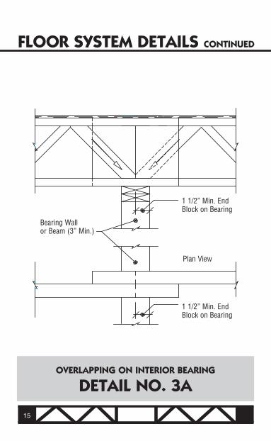
FLOOR SYSTEM DETAILS CONTINUED
OVERLAPPING ON INTERIOR BEARING
DETAIL NO. 3A
Bearing Wallor Beam (3” Min.)
1 1/2” Min. End Block on Bearing
Plan View
1 1/2” Min. End Block on Bearing
15
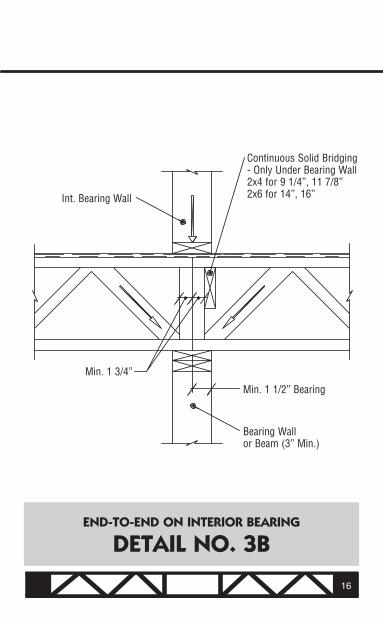
END-TO-END ON INTERIOR BEARING
DETAIL NO. 3B
Bearing Wallor Beam (3” Min.)
Min. 1 3/4”
Int. Bearing Wall
Min. 1 1/2” Bearing
Continuous Solid Bridging - Only Under Bearing Wall 2x4 for 9 1/4”, 11 7/8” 2x6 for 14”, 16”
16

FLOOR SYSTEM DETAILS CONTINUED
JOIST TO WOOD BEAM WITH APPROPRIATE HANGER
DETAIL NO. 4
Engineered or ConventionalWood Beam
Hanger
17

RECOMMENDED CONTINUOUS STRONGBACK BRIDGING
DETAIL NO. 5
Continuous Strongback Bridging Recommended Every 7’-0” Nailed asIndicated With (2) 3” Nails.
Framer is Advised to Install and Nail All Strongbacks Before Installation of the Sub Floor.
9 1/4” Joists - 2x4 Strongback11 7/8” Joists - 2x4 Strongback14” Joists - 2x6 Strongback16” Joists - 2x6 Strongback
18

FLOOR SYSTEM DETAILS CONTINUED
RECOMMENDED CONTINUOUS STRONGBACK BRIDGING (ALTERNATE)
DETAIL NO. 5A
Continuous Strongback Bridging Recommended Every 7’-0” Nailed as Indicated With (2) 3” Nails.
2x Block
Plan View
Framer is Advised to Install and Nail All Blocks and Strongbacks Before Installation of the Sub Floor.
9 1/4” Joists - 2x4 Strongback11 7/8” Joists - 2x4 Strongback14” Joists - 2x6 Strongback16” Joists - 2x6 Strongback
19
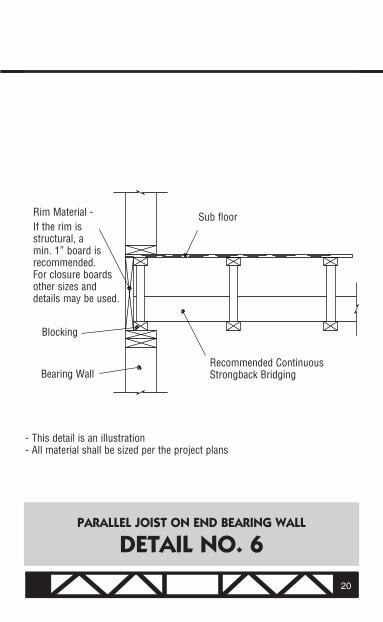
PARALLEL JOIST ON END BEARING WALL
DETAIL NO. 6
Rim Material -If the rim is structural, a min. 1” board is recommended. For closure boards other sizes and details may be used.
Blocking
Bearing Wall
Sub floor
Recommended Continuous Strongback Bridging
20
- This detail is an illustration- All material shall be sized per the project plans
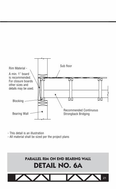
PARALLEL RIM ON END BEARING WALL
DETAIL NO. 6A
Rim Material -
A min. 1” board is recommended. For closure boards other sizes and details may be used.
Blocking
Bearing Wall
Sub floor
Recommended Continuous Strongback Bridging
- This detail is an illustration- All material shall be sized per the project plans
21

FLOOR SYSTEM DETAILS CONTINUED
E*
Engineering required. Engineered job drawings will specify gusset size and location and fastening.E*
CANTILEVERED SUPPORTING LOAD BEARING WALL
DETAIL NO. 8
22
Cantilever Sill Plate
Load Bearing Wall
OSB or Plywood Gusset Glued and Nailed to Top and Bottom Chords With Nails at Specified Spacing
Exterior Bearing Wallor Beam

SHORT CANTILEVER WITHOUT REINFORCEMENTSUPPORTING LOAD BEARING WALL
DETAIL NO. 8A
Varies According to Framing Members and Loads
Sill PlateMasonry Foundation Bearing Wall
Load Bearing Wall
Engineering required. Engineered job drawings will specify gusset size and location and fastening.E*
23
E*
FLOOR SYSTEM DETAILS CONTINUED
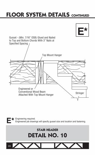
STAIR HEADER
DETAIL NO. 10
Engineering required. Engineered job drawings will specify gusset size and location and fastening.E*
E*Gusset - (Min. 7/16” OSB) Glued and Nailed to Top and Bottom Chords With 3” Nails at Specified Spacing
Top Mount Hanger
Engineered orConventional Wood BeamAttached With Top Mount Hanger
Stringer
24
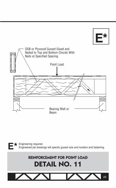
REINFORCEMENT FOR POINT LOAD
DETAIL NO. 11
Engineering required. Engineered job drawings will specify gusset size and location and fastening.E*
E*
25
OSB or Plywood Gusset Glued and Nailed to Top and Bottom Chords With Nails at Specified Spacing
Point Load
Bearing Wall or Beam
FLOOR SYSTEM DETAILS CONTINUED
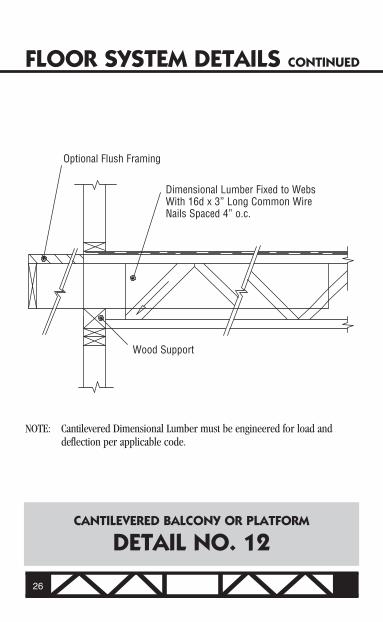
CANTILEVERED BALCONY OR PLATFORM
DETAIL NO. 12
26
NOTE: Cantilevered Dimensional Lumber must be engineered for load and deflection per applicable code.
Wood Support
Optional Flush Framing
Dimensional Lumber Fixed to Webs With 16d x 3” Long Common Wire Nails Spaced 4” o.c.

SOLID LUMBER CANTILEVERPERPENDICULAR TO Open Joist
DETAIL NO. 13 27
NOTE: Cantilevered Dimensional Lumber must be engineered for load and deflection per applicable code.
Support Nailed to Joist
DimensionalLumber
FLOOR SYSTEM DETAILS CONTINUED
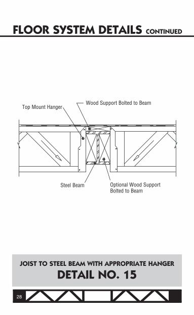
JOIST TO STEEL BEAM WITH APPROPRIATE HANGER
DETAIL NO. 15
28
Top Mount HangerWood Support Bolted to Beam
Optional Wood SupportBolted to Beam
Steel Beam

TYPICAL FIRE SEPARATION WALL
DETAIL NO. 16
29
Air Space or Fire-Rated Drywall According to Local Code
Masonry Wall
Continuous Solid Bridging 2x4 for 9 1/4”, 11 7/8”2x6 for 14”, 16”
Bearing Wall

FLOOR SYSTEM DETAILS CONTINUED
NON-BEARING WALL PARALLEL WITH JOISTS
OPTIONAL BRACING DETAIL
30
Non-Bearing Wall
Recommended Continuous Strongback Bridging
2x4 at StudLocation Top Block - Nailed to Sub floor Bottom Block - Nailed to the Bottom of the Top Chord (Nailed Together)
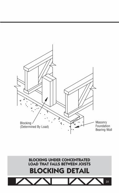
BLOCKING UNDER CONCENTRATED LOAD THAT FALLS BETWEEN JOISTS
BLOCKING DETAIL
MasonryFoundation Bearing Wall
Blocking(Determined By Load)
31

FLOOR SYSTEM DETAILS CONTINUED
BLOCKING UNDER CONCENTRATED LOAD ON PARALLEL END WALL
BLOCKING DETAIL
Cut OPEN JOIST Truss
2x Block Applied to End of Joist
MasonryFoundation Bearing Wall
Blocking(Determined By Load)
2x Block Applied to End of Joist
32
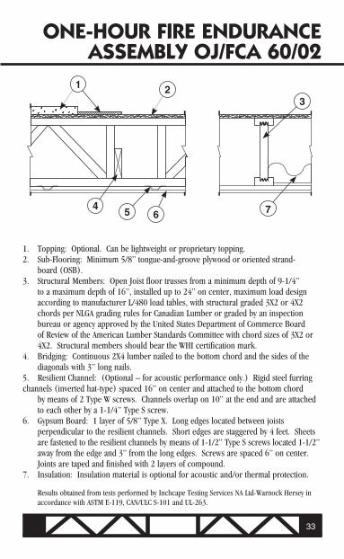
ONE-HOUR FIRE ENDURANCEASSEMBLY OJ/FCA 60/02
45 6
3
7
1 2
1. Topping: Optional. Can be lightweight or proprietary topping.2. Sub-Flooring: Minimum 5/8” tongue-and-groove plywood or oriented strand- board (OSB).3. Structural Members: Open Joist floor trusses from a minimum depth of 9-1/4” to a maximum depth of 16”, installed up to 24” on center, maximum load design according to manufacturer L/480 load tables, with structural graded 3X2 or 4X2 chords per NLGA grading rules for Canadian Lumber or graded by an inspection bureau or agency approved by the United States Department of Commerce Board of Review of the American Lumber Standards Committee with chord sizes of 3X2 or 4X2. Structural members should bear the WHI certification mark.4. Bridging: Continuous 2X4 lumber nailed to the bottom chord and the sides of the diagonals with 3” long nails.5. Resilient Channel: (Optional – for acoustic performance only.) Rigid steel furring channels (inverted hat-type) spaced 16” on center and attached to the bottom chord by means of 2 Type W screws. Channels overlap on 10” at the end and are attached to each other by a 1-1/4” Type S screw.6. Gypsum Board: 1 layer of 5/8” Type X. Long edges located between joists perpendicular to the resilient channels. Short edges are staggered by 4 feet. Sheets are fastened to the resilient channels by means of 1-1/2” Type S screws located 1-1/2” away from the edge and 3” from the long edges. Screws are spaced 6” on center. Joints are taped and finished with 2 layers of compound.7. Insulation: Insulation material is optional for acoustic and/or thermal protection.
Results obtained from tests performed by Inchcape Testing Services NA Ltd-Warnock Hersey in accordance with ASTM E-119, CAN/ULC S-101 and UL-263.
33
34
CODE APPROVALS ANDCERTIFICATIONModel Building Code Acceptance
Open Joist is accredited by International Code Council Evaluation Service Report Number ESR-1035 and is in compliance with the following codes: 2006 International Building Code (IBC), 2006 International Residential Code (IRC), BOCA National Building Code/1999 (BNBC), 1999 Standard Building Code (SBC), and the 1997 Uniform Building Code (UBC). Open Joist is accredited by the City of Los Angeles (RR#25376 and RR#25584), New York City (MEA#300-00-E), the city of Houston (#434B); and the state of Florida (FL#5828). Open Joist is certified by Canadian report #CCMC 12118R and is in compliance with Part 4 and Part 9 of the National Building Code of Canada 1995, the Ontario Building Code 1995; and CAN/CSA-086. 1-M94 standards for limit state design and controlled vibration standards. Code approval reports available at www.openjoist.com.
Third Party Certification
Intertek Testing Services, which uses theWarnock Hersey certification mark for engineered wood products, is the independent evaluation/ testing agency for certification of Open Joist’s manufacturing process.
Universal Forest Products is a member of the Wood Truss Council of America.

35
HANDLING, STORAGE NOTES

Universal Forest ProductsOpen Joist
www.openjoist.com
The tree logo is a registered trademark of Universal Forest Products, Inc., in the United States.
©2001-2007, 2009 Universal Forest Products All rights reserved.
The diagrams and instructions in this brochure are for illustration purposes only and are not meant to replace the work of a licensed professional. Any construction or use of the product must be in accordance with all local zoning and/or building codes. The consumer assumes all risks and liability associated with the construction or use of this product. The consumer or contractor should take all necessary steps to ensure the safety of everyone involved in the project, including, but not limited to, wearing the appropriate safety equipment. Except as contained in a written limited warranty supplied by Universal Forest Products (“Universal”), Universal does not provide any other warranty, either express or implied. Universal shall not be liable for any damages, including special, incidental or consequential damages which may result from the installation of this product. Installer and/or end user should not exceed load capacities. Universal makes no warranty as to design of wall and roof loads, and all loads should be verified by a licensed professional.
Universal Forest Products Eastern Division, Inc. manufactures the Open Joist product as a licensee of Distribution Open Joist 2000, Inc. All Open Joist product design and engineering calculations are created by the licensor, Distribution Open Joist 2000, Inc.
2430-273_5/09