Embed Size (px)
Citation preview
.... A':Rev. A
VALMONT TCE SITE
REMEDIAL INVESTIGATIONAFEASIBILITY STUDY (RI/FS)
FIELD SAMPLING PLAN
EIPA 'WORK ASSIGNMENT NO,. 040-RICO-031MPROJECT NO. N2107
RAC 3 PROGRAMCONTRACT NO. 68-S6-3003
WAY 2001
lit TETRA TECH NUS, INC.
1.0 BACKGROUND
1.1 INTRODUCTION
The U.S. Environmental Protection Agency (ERA) Region 3 tasked Tetra Tech NLIS under Contract No.68-S3-0003 to conduct groundwater and air sannpling and analysis under Work Assignment No. 040-
RICO-031 M at the Valrnont Trichloroethylene (TCE) Site in Hazle Township and West Hazleton,Pennsylvania. This Field Sampling Plan (FSP) discusses objectives and procedures for groundwatersampling of residential wells, monitoring wells, and air sampling to be completed at this site.
I.2 SITE DESCRIPTION
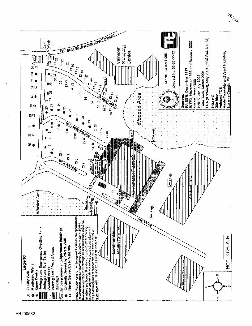
The Valrnont TCE Site in Hazle Township and West Hazleton, Luzerne County, Pennsylvania, oonsists ofChromatex Plant No. 2, an upholstery manufacturing plant at 423 Jaycee Drive, and known contaminatedgroundwater in the nearby residential neighborhood on Deer Run, Bent Pine, and Twin Oaks Roads(Figures 1 and 2). Aliases for the site include "Chromatex Plant" and "Valrnont Industrial Park(Chromatex)", and the site was irefenrecl to as the 'Valrnont TCE: Site" in an ERA Administrative ConsentOrder.
Chromatex Plant No. 2 (Chronnatex) is located at the edge of a large industrial park, and the residentialneighborhood is located about 100 feet northeast of its property boundary. The Vaimont Shopping Centeris about 200 feel: east of its property boundary. The Chrornatex: building has paved areas along the
northeast: and southwest sides of the building. A wooded area is located along the southeast side of theproperty. The Allsteel, Inc. building is located about 100 feet south of the properly boundary. TheContinental White Cap Inc. building is located directly west and across; the street from the property.
II,3 SITE: HISTORY AMD PREVIOUS INVESTGATtONS
The first known owner of the property on which Chromatex Plant No. 2 is located was CAN DO, Inc.,which constructed a building shell at the site in 1963. Wallace Metal Products, a coffin manufacturer,
bought the property in 1965 and sold it to Futura Fabrics, a division of Chelsea Industries, in 1972. Futura
manufactured knitted fabrics at the facility. The Vaimont Group of Paterson, New Jersey, purchased theproperly in 1978 and immediately leased it to Chromatex, Inc. Several partners of the Vaimont Group
1-1
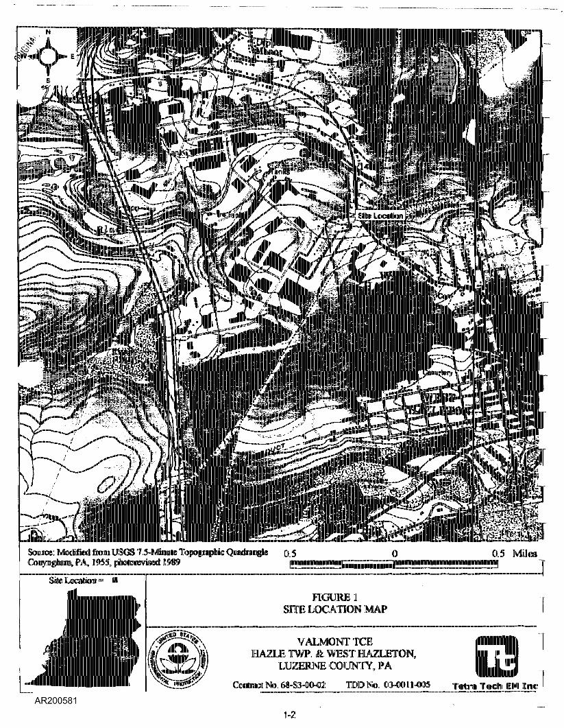
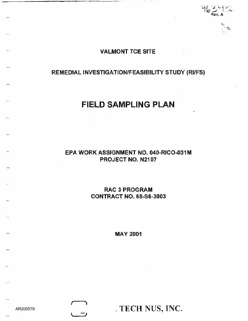
Source: Modified! fiom USGS 7.5-IMEhgmlK: l,, FA, 1 .955, ptenioirraiDdl 11!)'H9
() 5 0 05 Mil a
Skilc LaciilJbin
FKilllRJB 1SHE LOCATION MAP
VALMONTTCEHAZLE TWF. & WEST HAZLETON,
LUZERNE COUNTY, PACratract No. <»-S3-00-«!l IDDlSto, 03-00 1 .1-005 Tctra T«eh EIMI
1-2
1-3
were stockholders in Chromatex until December 198(3, when the outstanding stock of Chromatex was soldto Rossville Industries, Inc., of Rossville, Georgia, In November 1993, the Valmont Group sold the
property to Chromatex Properties, Inc., and the manufacturing operation to Gulp, Inc. The property iscurrently owned by Chromatex Properties, Inc. and is leased to Gulp, Inc. Since July 1978, the site facilityhas been used for upholstery fabric manufacturing operations.
Groundwater contamination at the site was discovered in October 1987 when sampling of private drinkingwaiter wells revealed the presence of high concentrations of TCE and lower concentrations of other volatileorganic compounds (VOCs). While investigating a September 1987 xylene spill at its facility, ContinentalWhite Cap (located to the west of Chromatex) reported to the Pennsylvania Depantnnent of EnvironmentalProtection (PADEP) that 48 micrograms per liter (ug/l) of TCE had been detected in a water samplecollected from, the housing development along Deer Run Road. PADEP subsequently sampled fourresidential wells on October 19 and 20, 1987, and detected TCE, 1,1,1-trichloroetnane (1,1,1-TCA), 1,1-dichloroethene (1,1-DCE). and cis-1,2-DCE in the samples. At PADEP's request, the U.S. Environ menialProtection Agency (EPA) initiated an investigation in October 1987 and provided bottled water and carbon
filters to residences affected by the TCE contamination. Further sampling by PADEP indicated the
presence of TCE in 23 residential wells on Deer Run, Bent Pine, and Twin Oaks Roads, at concentrations
ranging from 1 to 1,400 ug/l, and in the Chromatex facility well at a concentration of 2,200 ug/l.
During the October 1987 investigation, EPA performed a soil gas survey by collecting soil gas samples
from depths of 3 to 5 feet around the Chromatex plant. TCE was detected at concentrations ranging from
0.1 to 12.5 parts per million (pprni), with the highest concentrations along the rear of the plant. During thesoil! gas survey, EPA conducted a heaclspace analysis [chemical analysis of the air or gas that
accumulates at the top of a tank or other container] of the UST and detected a TCE concentration of 1,100ppnri. The LIST was drained of approximately 10,000 gallons of wastewater and nine 55-galldn drums ofbottom sludge on November 1C) and 11, 1987. Chromatex reported that analyses of the liquid revealed14,000 parts per billion (ppb) of TCE and lower levels of other VOCs, and that the tank was cleaned after
removal of the liquid and sludges and closed to prevent future use.
Chromatex reported that the LIST was; air-pressure tested after removal of the wastewater and sludge,and was found to be airtight Chirornatex: also reported that the piping associated with the LIST wasclogged with latex material. After the tank testing, PADEP determined that excavation of the lines wasnecessary and informed Chirornatex that it must: expose all lines to and from the lank for inspection. OnNovember 16,1987, PADEP and EPA inspected the exposed lines around the UST. The line excavationhad uncovered a break in the feed! line to the UST. Chromatex reported that the rupture occurred uponexcavation, however, an EPA representative who was on site at the time reported that the pipe was
1-4
broken prior to excavation. PADEP reported that the piping contained solidified latex and did not contain
liquid when it was uncovered, and that the broken portion of the pipe clearly showed corrosion and rust.
Also on November 16, 1987, PADEP and! Chromatex collected split: soil samples [samples collected from
the same location, divided between two parties, and analysed separately] from the excavated! area,trenches that held the pipes connecting the containment system within the Ibuildliing to the LIST. In additionto the soil samples, PADEP collected a sample of solidified latex near the uncovered broken pipe. Thelaboratory reported that TCE was detected in the percent range for the latex sample and that TCE wasdetected in all but one soil sample at concentrations ranging from 50 to 1,800,000 ug/kg, with the highest
concentration reported for the shallow sample collected beneath the broken pipe.
By November 17, 1987, EPA had provided bottled water and carbon filters to all affected residents, and
had re-sampled the wells. TCE was detected in the well samples at concentrations ranging from non-detect to 1,630 ug/l, and 1,1,1-TCA was detected at levels up to 273 ug/l. EPA determined that a more
permanent solution was needed, and subsequently funded the installation of public water supply
connections to all the houses in the neighborhood where TCE contamination had been found.
On November 19,1987, PADEP collected samples from the two tanker trucks that were holding the liquid
waste removed from the UST. Analyses revealed the presence of 720 to 3,500 mg/l) of TCE; 3.7 to 23
mg/l of 1,1,1-TCA; 0.3 to 1.7 mg/l of 1,1-DCA; and 0.065 mg/l of 1,1-DCE in one sample. PADEP
determined that the waste TCE was being stored in liquid and sludge forms in the LIST without notice to
DER and without a permit. A subsequent inspection by PADEP in December 1987 revealed that
Chromatex had purchased 267,347 pounds of TCE from November 1986 until December 1987 and that
approximately 54 tons (108,000 pounds) were unaccounted for after accounting for reclaimed TCE,
discharge to sewer, fabric retention, emission control equipment, and steam regeneration process. Therewere two 5,000-gallon aboveground storage tanks inside the plant: for new and reclaimed TCE:, and two
others for storing the latex coating mix used in the fabric-backing process.
The PADEP inspection revealed a distinct solvent odor at the plant and that one of the TCE tanks haddeveloped pinhole leaks. PADEP also observed that the side porthole on the tank was unbolted, A single
10,000-gallon underground storage tank (UST) located approximately 25 feet northwest of the buildingwas used for emergency spillage or overflow of hazardous materials stored within the facility. The USTacted as secondary containment for the indoor tank farm, and floor drains inside the plant carried spentTCE to the LIST. Chromatex did not have a permit for storage or disposal of hazardous waste in the UST.A storm drain existed in the vicinity of the former UST location, which was connected to an undergroundpipe that discharged to a drainage pathway at the southwest corner of the facility.
1-5
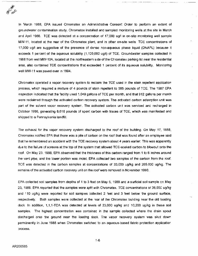
In March 1988, ERA issued Chromatex an Administrative Consent Order to perform an extent ofgroundwater contamination study. Chromatex installed and sampled monitoring wells at the site in Marchand April 1988. TCE: was detected! at a concentration of 17,000 ug/l in on-site monitoring well sampleMW-11, located at the rear of the Chromatex plaint, and in other on-site wells.. TCE concentrations of17,000 ug/l are suggestive of the presence of dense non-aqueous phase liquid (DNAPL) because itexceeds 1 percent of the aqueous solubility (1,100,000 ug/l) of TCE. Groundwater samples collected in1988 from well MW-1 OA, located at the northeastern side of the Chromatex parking lot near the residentialarea, also contained TCE: concentrations that exceeded 1 percent of its aqueous solubility. Monitoringwell MW-11 was paved over in 1994.
Chromatex operated a vapor recovery system to reclaim the TCE: used in the stain repellent: applicationprocess, which required a mixture of 4 pounds of stain repellent to 585 pounds of TCE. The 1987 ERAinspection indicated that the facility used 1,049 gallons of TCE per month, and that 912 gallons [>eir monthwere reclaimed through the activated carton recovery system. The activated carbon adsorption unit was
part of the solvent vapor recovery system. The activated carbon unit was serviced and recharged in
October 1986, generating 6,015 pounds of spent carbon with traces of TCE, which was manifested and
shipped to a Pennsylvania landfill.
The exhaust for the vapor recovery system discharged to the roof of the building. On May 17, 1988,
Chromatex notified EPA that there was a pile of carbon on the roof that was found after an employee saidthat he remembered an accident with the TCE recovery system about 4 years earlier. This was apparentlydue to the failure of screens at: the top of the system that allowed TCEi-soaked carton to blowout onto theroof. On May 23, 1988, EPA observed that the thickness of this carbon ranged from 1 to 6 inches aroundthe vent pipe, and the lower portion was moist. EPA collected two samples of the carton from the roof.TCI~ was detected in the carbon samples at concentrations of 33,000 ug/kg and 265,000 ug/kg. Theremains of the activated carbon recovery unit on the roof were removed in November 1993.
EPA collected soil samples from depths of 1 to 3 feet on May 5, 1988 and a surficial soil sample on May
23, 1988. EPA reported that the samples were split with Chromatex. TCE: concentrations of 38,000 ug/kgand 1110 ug/kg were reported for soil samples collected 2 feet and 3 feet below the ground surface,respectively. Both samples were collected at the rear of the Chromatex building near the old loading
dock. In addition, 1,1,1-TCA was detected at levels of 23,000 ug/kg and 110,200 ug/kg in these soilsamples. The highest concentration was contained in the sample collected where the drain spoutdischarged onto the ground near the loading clock. The vapor recovery system was shut downpermanently in June 1988 when Chromatex switched to an aqueous-based fabric protection applicationprocess.
1-6
- . ' ' ^
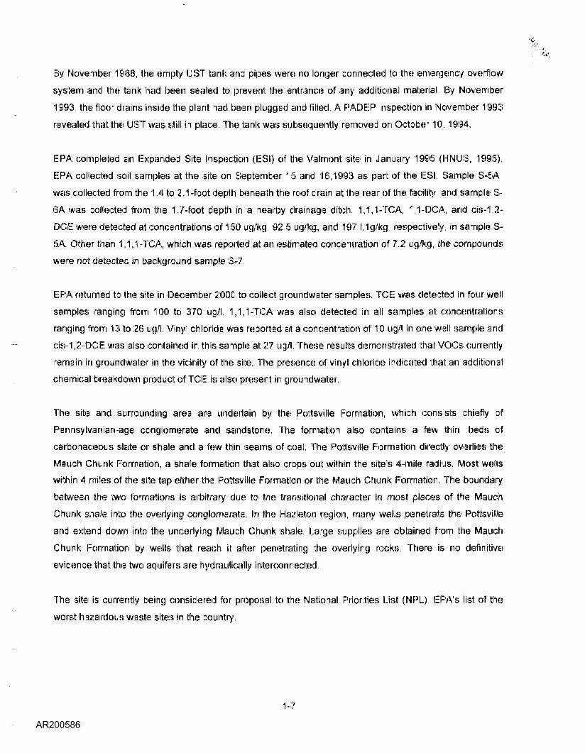
By November 1988, the empty LIST tank and pipes were no longer connected to the emergency overflow
system and the tank had been sealed to prevent the entrance of any additional material. By November1993, the floor drains inside the plant had been plugged and filled. A PADEP inspection in November 1993revealed that the LIST was still in place. The tank was subsequently removed on October 10, 1994.
EPA completed an Expanded Site Inspection (ESI) of the Valmont site in January 1995 (MINUS, 1995).
EPA collected soil samples at the site on September 15 and 16,1993 as part of the ESI. Sample S-5A
was collected from the 1.4 to 2.1-foot depth beneath the roof drain at the rear of the facility, and sample S-6A was collected from the 1.7-foot depth in a nearby drainage ditch. 1,1,1-TCA, 1,1-DCA, and cis-1,2-DCE were detected at concentrations of 150 ug/kg, 92.5 ug/kg, and 197 l.1g/kg, respectively, in sample 8-5A. Other than 1,1,1-TCA, which was reported at an estimated concentration of 7.2 ug/kg, the compoundswere not detected in background sample S-7.
EPA returned to the site in December 2000 to collect groundwater samples. TCE was detected in four well
samples ranging from 100 to 370 ug/l. 1,1,1-TCA was also detected in all samples at concentrationsranging from 13 to 26 ug/l. Vinyl chloride was reported at a concentration of 10 ug/l in one well sample andcis-1,2-DCE was also contained in this sample at 27 ug/l. These results demonstrated that VOCs currently
remain in groundwater in the vicinity of the site. The presence of vinyl chloride indicated that an additional
chemical breakdown product of TCE is also present in groundwater.
The site and surrounding area are underlain by the Pottsville Formation, which consists chiefly ofPennsylvanian-age conglomerate and sandstone. The formation also contains a few thin .beds ofcarbonaceous slate or shale and a few thin seams of coal. The Pottsville Formation directly overlies theMauch Chunk Formation, a shale formation that also crops out within the site's 4-mile radius. Most wellswithin 4 miles of the site tap either the Pottsville Formation or the Mauch Chunk Formation. The boundarybetween the two formations is arbitrary due to the transitional character in most places of the MauchChunk shale into the overlying conglomerate. In the Hazleton region, many wells penetrate the Pottsvilleand extend down into the underlying Mauch Chunk shale. Large supplies are obtained from the MauchChunk Formation by wells that reach it after penetrating the overlying rocks. There is no definitiveevidence that the two aquifers are hydraulically interconnected.
The site is currently being considered for proposal to the National Priorities List (IMPL), EPA's list of theworst hazardous waste sites in the country.
1-7

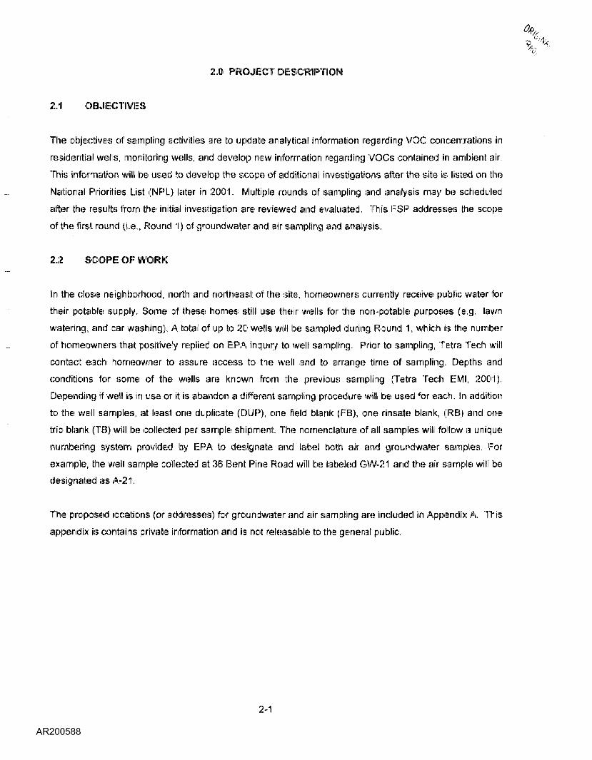
2.0 PROJECT DESCRIPTION
2.1 OBJECTIVES
The objectives of sampling activities are to update analytical information regarding VOC concentrations inresidential wells, monitoring wells, and develop new information regarding VOCs contained in ambient air.This infonrriiation will be used to develop the scope of additional investigations after the site is listed on theNational Priorities List (MPL) later in 2001. Multiple rounds of sampling and .analysis may be scheduled
after the results from the initial investigation are reviewed and evaluated. This FSP addresses the scopeof the first round (i.e., Round 1) of groundwater and air sampling and analysis.
2.2 SCOPE OF WORK
In the close neighborhood, north and northeast of the site, homeowners currently receive public vrater for
their potable supply. Some of these homes still use their wells for the non-potable purposes (e.g., lawnwatering, and car washing). A total of up to 20 wells will be sampled during Round 1, which is the number
of homeowners that positively replied on EPA inquiry to well sampling. Prior to sampling, Tetra Tech will
contact each homeowner to assure access to the well and to arrange time of sampling. Depths andconditions for some of the wells are known from the previous sampling (Tetra Tech EMI, 2001).
Depending if well is in use or it is abandon a different sampling procedure will be used for each. In addition
to the well samples, at least one duplicate (DUIP), one field blank (FB), one rinsale blank, (RB) and onetrip blank (TIB) will be collected per sample shipment. The nomenclature of all samples will follow a uniquenumbering system provided by EPA to designate and label both air and groundwater samples. Forexample, the well sample collected at 36 IBtent Pine Road will be labeled GVV-21 and the air sample will bedesignated as A-21.
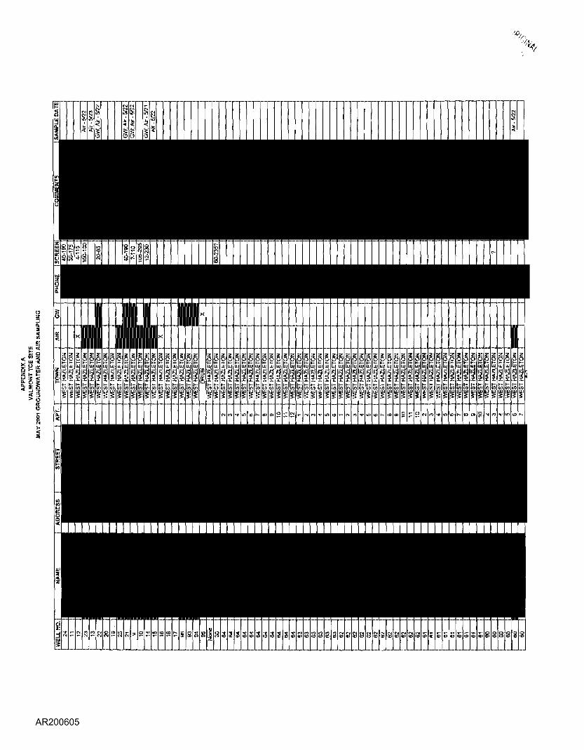
The proposed locations (or addresses) for groundwater and air sampling are included in Appendix A. Thisappendix is contains private information and is not releasable to the general public.
2-1

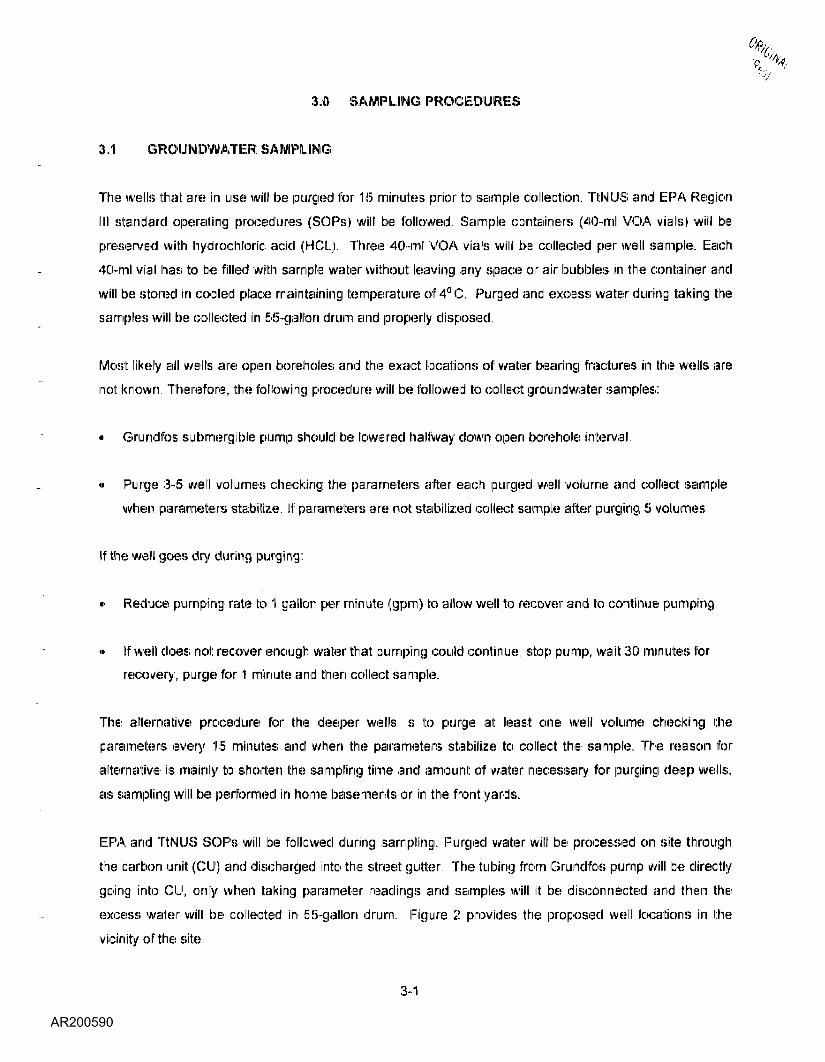
3.0 SAMPLING PROCEDURES
3,1 GROUNDWATER SAMPLING
The wells that are in use will be purged for 15 minutes prior to sample collection. TtNUS and IIIIPA Region111 standard operating procedures (SOPs) will be followed. Sample containers (40-ml VOA vials) will bepreserved with hydrochloric acid (HICIL). Three 40-ml VOA vials will be collected per well sample. Each
40-ml vial has to be filled with sample water without: leaving any space or air bubbles in the container andwill be stored in cooled place maintaining temperature of 4° C. Purged and excess water during taking thesamples will be collected in 55-gallon drum and properly disposed.
Most likely all 'wells are open boreholes and the exact locations of water bearing fractures in the wells arenot known. Therefore, the following procedure will be followed to collect groundwater samples:
« Grundfos submergible pump should be lowered hallway down open borehole interval.
• Purge 3-5 well volumes checking the parameters after each purged well volume and collect sample
when parameters stabilize. If parameters are not; stabilized collect sample after purging 5 volumes.
If the well goes dry during purging:
• Reduce pumping rate to 1 gallon per minute (gpm) to allow well to recover and to continue pumping.
« If well does not recover enough water that pumping could continue, stop pump, wait 30 minutes forrecovery, purge for 1 minute and then collect sample.
The alternative procedure for the deeper wells is to purge at least one well volume checking theparameters every 15 minutes and when the parameters stabilize to collect the sample. The reason foralternative is mainly to shorten the sampling tirne and announi: of water necessary for purging deep wells,as sampling will be performed in home basements or in the front yards.
EPA and TtNUS SOPs will be followed during sampling. Purged water will be processed on site throughthe carbon unit (CU) and discharged into the street: gutter, The tubing from Grundfos pump will be directlygoing into CU, only when taking parameter readings and samples will it be disconnected and then theexcess water will be collected in 55-gallon drum. Figure 2 provides the proposed well locations in thevicinity of the site.
3-1
Background groundwater samples will not be collected during Round 1. The generic SOP for groundwatersampling (TtNUS SOP SA-1-1) is contained in Appendix B.
3.2 AIR SAMPLING
The air sampling program will consist: of collecting approximately 4 liters of ambient: air in Sutirirnacanisters over a 4-hour period. A total of up to 35 air samples will be collected in addition to one trip blank(TIB) for each 10 samples. One duplicate sample (DUP) will be taken for each 20 samples. One flowregulator will be used for each air sample, except the trip blanks. EPA Method TO-14A or Method TO-15will be used for analysis of VOCs using gas chromatograph/mass spectrometer (GC/IMIS) equipment Thetechnical statement of work for air sampling analysis is included as Appendix: C. TtNUS hassubcontracted with Severn Trent: Laboratory (STL) in Santa Ana, California for laboratory servicesregarding air samples. Preliminary data will be provided from STL in 10 business; days; the raw datapackage will be provided in 28 calendar days.
Where possible, air samples will be collected from the lowest part of each residence, preferably thebasement. The intent is to locate the Summa canisters on the basement floor instead of suspended withinthe breathing zone. The canisters will be placed in such a manner to monitor the most likely vapor releaseof VOCs (e.g., near sunup pumps or near signs of flooding or dampness) from the unsaturated zone or theshallow groundwater table. Only one air sample will be collected from each designated residence duringRound 1.
The reporting limits (RLs) and method detection limits (MDLs) in parts per billion (ppb) for Method TO-14Aare provided in Appendix: C. Laboratory QC samples are included in the laboratory's subcontract.
One background air sample will be collected from either an outdoors location or from a residence outsidethe vicinity of the suspected groundwater plume attributable to the site.
The generic SOP for air monitoring and sampling (TtNUS SOP SA-2.2) is contained in Appendix B.
3-2
3.3 SAMPLE AND EQUIPMENT DECONTAMINATION
Personal protective equipment (PPE) and! sampling equipment used at this sites that are defined to be
disposable will be double-bagged and disposed of as dry industrial waste. Any non-disposable sampling
equipment used, such as water quality meter, water meter indicator or pumps, will be decontaminated
between sampling locations using a solution of non-phosphate detergent: and water. All decontaminationactivities will be conducted in accordance with TtNUS SOP SA-7.1 (Decontamination of Field Equipment
and Waste Handling). This SOP is contained in Appendix B. TtNUS will consult: with the ERA remedial
project: manager (RPM) to determine the proper disposal method for the purge water and decontamination
fluids.
All air sampling equipment (canisters and regulators) will be returned to STL for decontamination and
cleaning.
3-3

4.0 ANALYTICAL PARAMETERS
The EP'A Contract Laboratory Program Statement of Work (CLIP SOW OLM04.2) will analyze all water
samples collected for VOCs. Organic Low Concentration Method (OI..C03.1) will not be used because!most: of the wells that will be sampled are not drinking water wells.
4-1

5.0 QUALITY ASSURANCE; AND QUALITY CONTROL %.: -
5.1 RESPONSIBILITIES
The sampling team will be responsible for ensuring that sample quality and integrity are maintained inaccordance with the Quality Assurance and Quality Control Guidance for Removal Activities (EPA/540/G-
90/004), April 1990, and that the sample labeling and documentation are performed in accordance withapproved SOPs. Regulations for packaging, marking, labeling, and shipping of hazardous materials and
wastes are promulgated by the U.S. Department of Transportation (DOT). Air carriers that transport
hazardous materials, in particular, Federal Express, require connpliiance with the current International AirTransport Association (IIATA) Regulations, which apply to the shipment and transport of hazardousmaterials by air carrier. Tetra Tech will follow IATA regulations to ensure compliance.
5,? FIELD QC
For groundwater samples, field QC will consist of collecting and analyzing one field blank per 20 samplesper matrix, one trip blank per VOA shipment, one rinsate blank per 20 samples, and one duplicate per 20
samples, as well as completing chain-of-custody documentation and sample documentation in accordancewith TtNUS SA-6.3 (Documentation). Field blanks will be collected to test for contamination that couldpossibly be introduced by sample containers and preservatives, rinsate blanks will be collected to test: the
sampling equipment (pump) for the sample contamination. Trip blanks will be collected to test for
contaminants that could possibly be introduced by sample transport. Field duplicates sample will test thereproducibility of sampling procedures and results.
5.3 LABORATORY QC
Laboratory QC will comply with all EPA requirements for laboratory QC. CLIP analysis will consist of all
QC stated in the CLIP SOW and includes all! forms and deliverables required in the SOW
5.4 DATA VALIDATION
Data validation for all groundwater and air samples will be performed by ERA Region III Central Regional
Laboratory's Quality Assurance Staff in accordance with EPA Region III Modifications to the EPA CLIPNational Functional Guidelines for Data Review for all samples (EPA, 1993). TtNUS will briefly review the
air sampling results for conformance with the terms of the laboratory services subcontract; however,TtNUS will not validate the air sampling results.
5-1

6.0 DELIVERABLES
Information gathered from this sampling event will be compiled into a sampling trip report, which willinclude 'field notes, sampling information, and analytical results,
6-1

7.0 HEALTH AND SAFETY
A separate health and safely plan has been prepared under separate cover for the field sampling effort.
7-1

REFERENCES
Halliburton NUS Corporation, 1995. Expanded Site Inspection for Valmont TCE Site, Hazleton,Pennsylvania. Wayne, Pennsylvania. January.
Tetra Tech NUS Standard Operating Procedures, 1999-2000. Pittsburgh, Pennsylvania.
Tetra Tech EMI, 2001. Trip Report for the Valmont TCE Site, Hazleton, Pennsylvania. Boothwyn,
Pen nsy Iva in iia. February
U.S. ERA Region III Central Regional Laboratories, 1993. Modifications to the Contract Laboratory
Program National Functional Guidelines for Organic and Inorganic Data Review. Annapolis, Maryland.
November.
U.S. ERA Region III 2000, Risk-Based Concentration Table.. Superfund Technical Support Section.
Philadelphia, Pennsylvania. October 5.
U.S. ERA Region III, 2001. Draft Final MRS Documentation Record, Valmont TCE Site, Hazleton,
Pennsylvania. Hazardous Site Control Division. Philadelphia, Pennsylvania. March.
R-1

\,
APPENDIX A
PROPOSED SAMPLE LOCATIONS STATEMENT OF WORK FORAIR SAMPIJE ANALYSIS
s
- --
:-- --
gga a
---- --- --- -- --
- -- -
- -- -- -- --
- --- --- --- - - -- ---- - -- -- - -- ------
- -- -- - --
- -
S! S Si S g! 8' 3
-
Si S
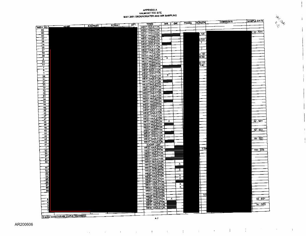
ArrE-DiXAvALaONTTCEiSTe
MAY 2001 QRGUNDWATEP. A~D AJR- SAMrtJNG
---- -- ------- -- ------------ -- ------- -- ------ -- ----- -- ------- -- ------- ----- -- ------- -- ------ -- ----- -- ------- -- ------ -- ----- -- ------- -- ------ -- ----- -- ------- -- ------ -- ------ ------- -- --------- --------- --
--------- ------------------- -- -- --------------- ----- - ---------------- ------- --
------ -- ----- -- ----- -- -------- ----- -- ------- -- -------- -------
-------- ------ --- - ------ ---- - ----- ---------- ------ -
-------- ------
-------- ----- -- ------- -- ------ -- ----- -- ------- -- ------------ -- ------- -- ------------------ --------------
--------- ------------------------- --
-- ----- -- ------- -- ----------- -- ----------- --
------ -- -------- -- ------ -- -------- -- ------ -- ------ -- ------- ------ -- ------- ------ -- -------- -- ------ -- -------- -- -------- - -------- -- ------ -- -------- -- ------ -- -------- -- ----------- -- ------ -- -------- -- ------ -- -------- -- ----- -------- -- ------- -- -------- -- ------ -- -------- -- ------ -- -------- --
-------- --------- -- - -----
-- - ----- - -- - ------- --- -- ------
----------------------
----------- - ---------- - ---------- - -------- - --------- - --------- - ---------- - ---------- -
------------ ------- -- ------------- ----------- --
-- -- ----- ---------- --- -- --- -
---------- - ---------- - ---------- - ---------- - ---------- - --------- - ----------- -- ----------- --
-----------------------
----- -- -------- -- ------ -- ------- ------- -- -------- --
---- -- -------- -- ------ -- -------- -- ------ -- -------- --
------------- -------------------------- -- -- - ----- -- - ----- - --------
------ -- ------ -- -------- --
-------- -- ----------- -- ------------------ - ------- --
----------------- -- ------- -- ---------- - ---------- - ----------- -
----------------- -- ------- -- ------------------------------- -- ---------------------------- -- --------------------- -- ------- --------------------- -- --------
-- ------------------ -- ---------
-------- -- --------- --------------------- -- --- - ---------------------------- --
--------
------------- ----------------------------
--------- -- --------- ------ -- ------- -- ------- --
------ -- -------- -
APPENDIX B
TETRA TECH IMIUS SOPs
TETRA TECH NUS, INC.
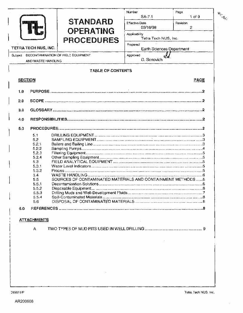
STANDARDOPERATINGPROCEDURES
NumberSA-7.1
(Effective Date03/16/96
Page1 of 9
Revision
ApplicabilityTetraTech NUS, Inc.
PreparedEarth Sciences Department
Subject DECONTAMINATION OF FIELD EQUIPMENT
AMD WASTE HANDLING
ApprovedD. Seinovich
TABLE OF CONTENTS
SECTION PAGE
1.0 PURPOSE.......................................................................1..................................................................2
2.0 SCOPE ................................................................................................................................................2
3.0 GLOSSARY..............................................
5.0' PROCEDURES..................................................................................................................................
5.1 DRILLING EQUIPMENT..................................................................................................35.2 SAMPLING EQUIPMENT..................................................:.............................................35.2.1 Bailers and Bailing Line...................................................................................................35.2.2 Sampling Pumps..............................................................................................................45.2.3 Filtering Equipment..........................................................................................................55.2.4 Other Sampling Equipment..............................................................................................55.3 FIELD ANALYTICAL EQUIPMENT.................................................................................55.3.1 Water Level! Indicators.....................................................................................................55.3.2 Probes.............................................................................................................................55.4 WASTE HANDLING ........................................................................................................65.5 SOURCES OF CONTAMINATED MATERIALS AND CONTAINMENT METHODS ......65.5.1 Decontamination Solutions..............................................................................................65.5.2 Disposable Equipment.....................................................................................................65.5.3 Drilling Muds and Well-Development Fluids....................................................................?5.5.4 Spill-Contaminated Materials...........................................................................................85.6 DISPOSAL OF CONTAMINATED MATERIALS .........................................................:...8
6.0 REFERENCES..................................................................................................................................^
AJTACHMiNTS
A TWO TYPES OF MUD PITS USED IN WELL DRILLING ...................................................... 9
019611/P Tetra Tech NUS, Inc.
Subject DECONTAMINATION OF FIELD•<- EQUIPMENT AND WASTE
HANDLING
NumberSA-7.1
Revision2
Page2 Of 9
l-ilfective Date03/16/918
1.0 PURPOSE
The purpose of this procedure is to provide guidelines regarding the appropriate procedures to be followedwhen decontaminating drilling equipment, monitoring well materials, chemical sampling equipment andfield analytical equipment.
2.0 SCOPE:
This procedure addresses drilling equipment: and monitoring well materials decontamination, as well aschemical sampling and field analytical equipment decontamination. This procedure also provides generalreference information on the control of contaminated materials.
3.0 GLOSSARY
Add - For decontamination of equipment: when sampling for trace levels of inorganics, a 10% solution ofnitric acid in deionized water should be used. Due to the leaching ability of nitric acid, it should not beused on stainless steel.
AJcoDox/LJauinox - A brand of phosphate-free laboratory-grade detergent.
Dejonized_Water - Deionized (analyte free) water is tap water that has been treated by passing through astandard deionizing resin column. Deionized water should contain no detectable heavy metals or otherinorganic compounds at or above the analytical detection limits for the project.
PotabJeWatex - Tap water used from any municipal water treatment system. Use of an untreated potablewater supply is not an acceptable substitute for tap water.
Solvent - The solvent of choice is pesticide-grade Isopropanoll. Use of other solvents (methanol, acetone,pesticide-grade hexane, or petroleum ether) may be required for particular projects or for a particularpurpose (e.g. for the removal of concentrated waste) and must be justified in the project planningdocuments. As an example, it may be necessary to use hexane when analyzing for trace levels ofpesticides, PCBs, or fuels. In addition, because many of these solvents are not miscible in water, theequipment should be air dried prior to use. Solvents should not be used on IPVC equipment or wellconstruction materials.
4,0 RESPONSIBILITIES
ProjicLManager - Responsible for ensuring that all field activities are conducted in accordance withapproved project plan(s) requirements.
fjeJgl_Ojaejra igjTSj=ejg r_(FOLi - Responsible for the onsite verification that all field activities areperformed" in compliance with approved Standards Operating Procedures or as otherwise dictated by theapproved project plan(s).
5.0 PROCEDURES
To ensure that: analytical chemical results reflect: actual contaminant concentrations present at samplinglocations, the various drilling equipment and chemical sampling and analytical equipment used to acquirethe environment sample must be properly decontaminated. Decontamination minimizes the potential forcross-contamination between sampling locations, and the transfer of contamination off site.
019611/P TetraTech NUS, Inc.
Subject DECONTAMINATION OF FIELDEQUIPMENT AND WASTEHANDLING
NumberSA-7.1
Revision2
Page3 Of 9
[Effective Date03/16/98
5.1 Drillinici Equipment
Prior to the initiation of a drilling program, all drilling equipment involved in field sampling activities shall bedecontaminated by steam cleaning at a predetermined area. The steam cleaning procedure shall beperformed using a high-pressure spray of heated potable water producing a pressurized stream of steam.This steam shall be sprayed directly onto all surfaces of the various equipment which might contactenvironmental samples. The decontamination procedure shall be performed until all equipment is free ofall visible potential contamination (dirt, grease, oil, noticeable odors, etc.) In addition, this decontaminationprocedure shall be performed at the completion of each sampling and/or drilling location, including soilborings, installation of monitoring wells; test pits, etc. Such equipment shall include drilling nigs, backhoes,downhole tools, augers, well casings, and screens. Where the drilling rig is set to perform multiple boringsat a single area of concern, the steam-cleaning of the drilling rig itself may be waived with proper approval,Downhole equipment, however, must always be steam-cleaned between borings, Where PVC wellcasings are to be installed, decontamination is not required if the manufacturer provides these casings infactory-sealed, protective, plastic sleeves (so long as the protective packaging is not compromised untilimmediately before use).
The steam cleaning area shall be designed to contain decontamination wastes and waste waters and canbe a lined excavated pit or a bermed concrete or asphalt pad. For the latter, a floor drain must beprovided which is connected to a holding facility. A shallow above-ground tank: may be used or a pumpingsystem with discharge to a waste tank may be installed.
In certain cases such an elaborate decontamination pad is not possible. In such cases, a plastic linedgravel bed pad with a collection system may serve as an adequate decontamination area. Alternately, alined sloped pad with a collection pump installed at the lower end may be permissible. The location of thesteam cleaning area shall be onsite in order to minimize potential impacts at certain sites.
Guidance to be used when decontaminating drilling equipment shall include:
* As a general rule, any part of the drilling rig which extends over the borehole, shall be steam cleaned.
« All drilling rods, augers, and any other equipment which will be introduced to the hole shall be steamcleaned.
" The drilling rig, all rods and augers, and any other potentially contaminated equipment: shall bedecontaminated between each well location to prevent cross contamination of potential hazardoussubstances.
Prior to leaving at the end of each work clay and/or at the completion of the drilling program, drilling rigsand transport vehicles used onsite for personnel or equipment transfer shall be steam cleaned, aspracticable. A drilling rig left at: the drilling location does not need to be steam cleaned until it is finisheddrilling at that location.
Error! Bookmark not defined.5.2 Samplinq Equipment
5.2.1 Illiiiileins; and l-ljiiling Line
The potential for cross-contamination between sampling points through the use of a common bailer or itsattached line is high unless strict procedures for decontamination are followed." For this reason, it ispreferable to dedicate an individual bailer and its line to each sample point, although this does noteliminate the need for decontamination of dedicated bailers. For non-dedicated sampling equipment, thefollowing conditions and/or decontamination procedures must be followed.
019611/P Tetra Tech NILIS, Inc.
Subject DECONTAMI NATION OF ("HELD>-" • EQUIPMENT AND WASTE
HANDLING
NumberSA-7..1
Revision2
Page4 of 9
l-ffective Date03/16/98
Before the initial sampling and sifter each successive sampling point, the bailer must be decontaminated.The following steps are to be performed when sampling for organic contaminants. Note: contract-specificrequirements may permit alternative procedures.
• Potable water rinse« Alconox: or Liquinox detergent wash» Scrubbing of the line and bailer with a scrub brush (may be required if the sample point is heavily
contaminated with heavy or extremely viscous compounds)» Potable water rinse» Rinse with 10 percent nitric acid solution*» Deionized water rinse» Pesticide-grade isopropanol (unless otherwise required)» Pesticide-grade hexane rinse**« Copious distilled/Deionized water rinse» Air dry
If sampling for volatile organic compounds (VOCs) only, the nitric acid, isopropanol, and hexane rinsesmay be omitted. Only reagent grade or purer solvents are to be used for decontamination. Whensolvents are used, the bailer must be thoroyghjy. dry before using to acquire the next sample.
In general, specially purchased pre-cleaned disposable sampling equipment is not decontaminated (nor isan equipment rinsate blank collected) so long as the supplier has provided certification of cleanliness. Ifdecontamination is performed on several bailers at once (i.e., in batches), bailers not immediately usedmay be completely wrapped in aluminum foil (shiny-side toward equipment) and stored for future use.When batch decontamination is performed, one equipment rinsate is generally collected from one of thebailers belonging to the batch before it is used for sampling.
It is recommended that clean, dedicated braided nylon or polypropylene line be employed with each baileruse.
5.2.2 Sampling Pump®
Most sampling pumps are low volume (less than 2 gpirn) pumps. These include peristaltic, diaphragm, air-lilt, pitcher and bladder purnps, to name a few. If these pumps are used for sampling from more than onesampling point, they must be decontaminated prior to initial use and after each use.
The procedures to be used for decontamination of sampling purnps compare to those used for a bailerexcept that the 10 percent nitric acid solution is omitted, Each of the liquid factions is to be pumpedthrough the system. The amount of pumping is dependent upon the size of the pump and the length ofthe intake and discharge hoses. Certain types of pumps are unacceptable for sampling purposes. Forperistaltic purnps, the tubing is replaced rather than cleaned.
An additional problem is introduced when the pump relies on absorption of water via an inlet or outlethose. For organic sampling, this hose should be Teflon. Other types of hoses leach organics (especiallyphthalate esters) into the water being sampled or adsorb organics from the sampled water. For all othersampling, the hose should be Viton, polyethylene, or polyvinyl chloride (listed in order of preference).
Due to the leaching ability of nitric acid on stainless steel, this step is to be omitted if a stainlesssteel sampling device is being used and metals anal/sis is required with detection limits less Itianapproximately 50 ppb.If sampling for pesticides, PCBs, or fuels.
019611/P Tetra Tech NUS, Inc.
Subject DECONTAMI NATION OF FIELDEQUIPMENT AND WASTEHANDLING
NumberSA-7.1
Revision2
Page;5 of 9
Effective Date03/16/98
Whenever possible, dedicated hoses should be used. It is preferable that these types of pumps not beused for sampling, only for purging.
5.2.3 Filtering Equipment
On occasion, the sampling plan may require acquisition of filtered groundwater samples. Field-filtering isaddressed in SOIP 3A-6.1I and should be conducted as soon after sample acquisition as possible, To thisend, three basic filtration systems are most commonly used: the in-line disposable Teflon filter, the inertgas over-pressure filtration system, and the vacuum filtration system.
For the in-line filter, decontamination is not required since the filter cartridge is disposable, however, thecartridge must be disposed of in an approved receptacle and the intake and discharge lines must still bedecontaminated or replaced before each use.
For the over-pressure and the vacuum filtration systems, the portions of the apparatus which come incontact with the sample must be decontaminated as outlined in the paragraphs describing thedecontamination of bailers. (Note: Varieties of both of these systems come equipped from themanufacturer with Teflon-lined surfaces for those that would come into contact with the sample. Thesefiltration systems are preferred when decontamination procedures must be employed.)
5.2,4 Other Sampling Equipment
Field tools such as trowels and mixing bowls are to be decontaminated in the same manner as describedabove.
5-3
5.3.1 Water Level Indicators
Water level indicators that come into contact with groundwater must: be decontaminated using thefollowing steps:
« Rinse with potable water» Rinse with deionized water
Water level indicators that do not come in contact with the groundwater but may encounter incidentalcontact during installation or retrieval need only undergo the first and last steps stated above.
5.3.2 Probes
Probes (e.g., phi or specific-ion electrodes, geophysical probes, or thermometers) which would come indirect contact with the sample, will be decontaminated using the procedures specified above unlessmanufacturer's instructions indicate otherwise (e.g., dissolved oxygen probes). Probes that contact avolume of groundwater not used for laboratory analyses can be rinsed with deionized water. For probeswhich make no direct contact, (e.g., OVA equipment) the probe is self-cleaning when exposure touncontaminated air is allowed and the housing can be wiped clean with paper-towels or cloth wetted withalcohol.
S,4 Wash;. Hand lino
For the purposes of these procedures, contaminated materials are defined as any byproducts of fieldactivities that are suspected or known to be contaminated with hazardous substances. These byproducts
019611/P Tetra Tech MIJS, Inc.
Subject DECONTAMINATION OF FIELDEQUIPMENT AND WASTE
S>: HANDLING
NumberSA-7.1
Revision2
Page6 of 9
Effective Date03/16/138
include such materials; as decontamination solutions, disposable equipment, drilling mud;; well-development fluids, and spill-contaminated materials and Personal Protection Equipment (PPE).
The procedures for obtaining permits for investigations of sites containing hazardous substances are notclearly defined at present. In the absence of a clear directive to the contrary by the EPA and the slates, itmust be assumed that hazardous wastes generated during liieldl activities will require compliance withFederal agency requirements for generation, storage, transportation, or disposal. In addition, there maybe state regulations that govern the disposal action. This procedure exclusively describes the technicalmethods used to control contanninatedi materials.
The plan documents for site activities must include a description of control procedures for contaminatedmaterials. This planning strategy must assess the type of contamination, estimate the amounts that wouldbe produced, describe containment equipment and procedures, and delineate storage or disposalmethods. As a general policy, it is wise to select investigation methods that minimize the generation ofcontaminated spoils. Handling and disposing of potentially hazardous materials can be dangerous andexpensive. Until sample analysis is complete, it is assumed that all produced materials are suspected ofcontamination from hazardous chemicals and require containment.
5.5 :'L<ME£;<i!lJ3iJ:i
5.5.1 Decontamination Solution!;;
All waste decontamination solutions and rinses must be assumed to contain the hazardous chemicalsassociated with the site unless there are analytical or oilier data to the contrary. The waste solutionvolumes could vary from a few gallons to several hundred gallons in cases where large equipmentrequired cleaning.
Containerized waste rinse solutions are best stored in 55-gallon drums (or equivalent containers} that canbe sealed until ultimate disposal at an approved facility, Larger equipment: such as backhoes and tractorsmust be decontaminated in an area provided with an impermeable liner and a liquid collection system. Adecontamination area for large equipment could consist of a berimed concrete pad with a floor drainleading to a buried holding tank.
5.5.2 Disposi a ble Equ ipment
Disposable equipment that: could become contaminated during use typically includes PPE, rubber gloves,boots, broken sample containers, and cleaning-wipes. These items are small and can easily be containedin 55-gallon drums with lids. These containers should be closed at the end of each work clay and uponproject completion to provide secure containment until disposed.
5.5.3 Drilling Muds and Well-Development Fluids
Drilling muds and well-development fluids are materials that may be used in groundwater monitoring wellinstallations. Their proper use could result in the surface accumulation of contaminated liquids and mudsthat require containment. The volumes of drilling muds and well-development fluids used depend on welldiameter and depth, grounclwater characteristics, and geologic formations; There are no simplemathematical formulas available for accurately predicting these volumes. It is best to rely on tineexperience of reputable well drillers familiar with local conditions and the well installation techniquesselected. These individuals should be able to estimate the sizes (or number) of containment structuresrequired. Since guesswork is involved, it is recommended that an slight excess of the estimated amountof containers required will be available.
019611/P Tetra Tech NUS, Inc.
Subject DECONTAMINATION OF FIELDEQUIPMENT AND WASTEHANDLING
NumberSA-7.1
Revision2
Page7 of 9
[Effective Date03/16/98
Drilling muds are mixed and stored in what is commonly referred to as a mud pit. This mud pit consists ofa suction section from which drilling mud is withdrawn and pumped through hoses, down the drill pipe tothe bit, and back up the hole to the settling section of the mud pit. In the settling section, the mud'svelocity is reduced by a screen and several flow-restriction devices, thereby allowing the well cuttings tosettle out of the mud/fluid.
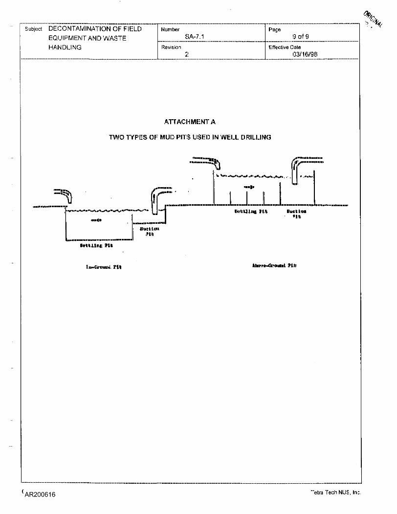
The mud pit may be either portable above-ground tanks commonly made of steel (which is preferred) orstationary in-ground pits as depicted in Attachment A. The above-ground tanks have a major advantageover the in-ground pits.because the above-ground tanks isolate the natural soils from the contaminatedfluids within the drilling system. These tanks are also portable and can usually be cleaned easily.
As the well is drilled, the cuttings that accumulate in the settling section must be removed. This is bestdone by shoveling them into drums or other similar containers. When the drilling is complete, the contentsof the above-ground tank are likewise shoveled or pumped into drums, and the tank is cleaned and rnadeavailable for its next use.
If in-ground pits are used, they should not extend into the natural water table. They should also be linedwith a bentonite-cement mixture followed by a layer of flexible inn permeable material such as plasticsheeting. Of course, to maintain its impermeable seal, the lining material used would have to benonreactive with the wastes, An advantage of the in-ground pits is that well cuttings do not: necessarilyhave to be removed periodically during drilling because the pit can be made deep enough to contain them.Depending on site conditions, the in-ground pit may have to be totally excavated and refilled withuncontaminated natural soils when the drilling operation is complete.
When the above-ground tank or the in-ground pit is used, a reserve tank or pit should be located at thesite as a backup system for leaks, spills, and overflows. In either case, surface drainage should be suchthat any excess fluid could be controlled within the immediate area of the drill site.
The containment procedure for well-development fluids is similar to that for drilling muds. The volume andweight of contaminated 'Fluid will be determined by the method used for development. When a new well ispumped or bailed to produce clear water, substantially less volume and weight of fluid result than whenbackwashing or high-velocity jetting is used.
5.5.4 Spill-Contaminated lUhiteiriate
A spill is always possible when containers of liquids are opened or moved. Contaminated sorbents andsoils resulting from spills must be contained. Small quantities of spill-contaminated materials are usuallybest contained in drums, while larger quantities can be placed! in lined pits or in other irnpermeablestructures. In some cases, onsite containment may not be feasible and immediate transport: to anapproved disposal site will be required.
5.6 Disposal of 'Contaminated Materials
Actual disposal techniques for contaminated materials are the same as those for any hazardoussubstance, that is, incineration, landfilling, treatment, and so on. The problem centers around theassignment of responsibility for disposal. The responsibility1 must be determined and agreed upon by allinvolved parlies before the field work starts. If the site owner or manager was involved in activities thatprecipitated the investigation, it seerns reasonable to encourage his acceptance of the disposal obligationIn instances where a responsible party cannot be identified, this responsibility may fall on the publicagency or private organization investigating the site.
Another consideration in selecting disposal methods for contaminated materials is whether the disposalcan be incorporated into subsequent site cleanup activities. For example, if construction of a suitable
019611/P Tetra Tech MUS, Inc.
Subject DECONTAMI NATION OF Fl ELDEQUIPMENT AND WASTEHANDLING
NumberSA-7.1
Revision2
Page8 of 9
Effective Date03/16/98
onsite disposal structure is expected, contanrliniated materials genenatedi during the investigation should bestored al: the site for disposal with other site materials;. In this case, the initial containment structures;should be evaluated for use as long-term storage structures, Also, other site conditions such as drainagecontrol, security, and soil type must be considered so that proper storage is provided, If onsite storage isexpected, then the containrnent structures should be specifically designed for that purpose.
6.0 REFERENCES
Brown & Root Environmental: Standard Operating Procedure No. 4.33, Control of Contaminated Material.
019611/P Tetra Tech NUS, Inc.
Subject DECONTAMINATION OF FIELDEQUIPMENT AND WASTEHANDLING
NumberSA-7.1
Revision
Page9 of 9
Effective Date03/16/98
ATTACHMENT A
TWO TYPES OF IWIUD PITS USED IN WELL DRILLING
.««•«,„„• ,1 I •'.<«<>»
]|'I,U fuelttoil
INlft
mi
i:m..«imiiiiji rim ff'Ml
019611/P Tetra Tech NLIS, Inc.
ItTETRA TECH NUS, INC.
STANDARDOPERATINGPROCEDURES
NumberSA-1-1
Effective06/9©
Page1 Of 27
Revision
ApplicabilityTetra loch NUS, Inc.
PreparedEarth Sdie nces Department
SubjectGROUNDWATER SAMPLE ACQUISITION ANDONSITE WATER QUALITY TESTING
ApprovedD. Senovich
TABLE OF CONTENTS
SECTION PAGE
1.0 PURPOSE................................................................................................... ^
2.0 SCOPE........................................................................................ ^
3.0 GLOSSARY.........................................................;.....................__,,..,.,..,,.,...,..,..,.,...,.,....,.,.,.,..,..,,.,,..,,...,,,;i!
4.0 RESPOMSIBIUITIES ..........................................................................................................................2
S.O PROCEDURES ...................................................................................................™...........................-3
5.1 GENERAL....................................................................................................................... 35.2 SAMPLING, MONITORING, AND EVACUATION EQUIPMENT...................................45.3 CALCULATIONS OF WELL VOLUME........................................................................... 45.4 EVACUATION OF STATIC WATER (PURGING).......................................................... 55.4.1 General........................................................................................................................... 55.4.2 Evacuation Devices........................................................................................................ 55.5 o N SITE;: WATER Q uALITY TESTIIMG ........................................................................... 75.5.1 Measurement of pH ........................................................................................................ 75.5.2 Measurement of Specific Conductance.......................................................................... 95.5.3 Measurement of Temperature...................................................................................... 115.5.4 M easurement of IDissolved Oxygen ..............................................................................115.5.5 M easu reme nt of Oxidation-Red uctton Potential........................................................... 135.5.6 Measurement of Turbidity............................................................................................. 145.5.7 Measurementof Salinity ............................................................................................... 155.6 SAMPLING...........................................................................................:....................... 165.6.1 Sampling Plan............................................................................................................... 165.6.2 Sampling Methods........................................................................................................ 175.7 LOW FLOW PURGING AND SAMPLING.................................................................... 185.7.1 Scope & Application...................................................................................................... 185.7.2 Equipment..................................................................................................................... 195.7.3 Purging and Sampling Procedure................................................................................... 19
6.0 REFERENCES ............................................................................................».TO.._. ..-....—...-21
'ATTACHMENTSA PURGING EQUIPMENT SELECTION ............................................................................. 22B SPECIFIC CONDUCTANCE OF 1 MOLAR KCII AT VARIOUS TEMPERATURES ....... 25C VARIATION OF DISSOLVED OXYGEN CONCENTRATION IN WATER
AS A FUIMCTIOM OF TEMPERATURE AND SAL!NITY .................................................. 26
019611/P Tetra lech NUS, line,
SubjectGROUNDWATER SAMPLEACQUISITION AND ONSITEWATER QUALITY TESTING
NumberSA-1-1
Revision4
Page2 of 27
Effective Date06/99
1,0 PURPOSE
The purpose of 'this procedure is to provide general reference information regarding the sampling ofgroundwater wells.
2.0 SCOPE
This procedure provides information on proper sampling equipment, ensile water quality testing, andtechniques for groundwater sampling. Review of the information contained herein will facilitate planningof the field sampling effort by describing standard sampling techniques. The techniques described shallbe followed whenever applicable, noting that site-specific conditions or project-specific plans may requiremodifications to methodology.
3,0 GLOSSARY
Conductivity --• Conductivity is a numerical expression of the ability of an .aqueous solution to carry anelectric current. This ability depends on the presence of ions, their total concentration, mobility, valence,and relative concentrations, and on temperature of measure. Conductivity is highly dependent ontemperature and should be reported at: a particular temperature, i.e., 20.2 rnS/crri at 14C.
PJs^olvedjpxygjn (P.PJ "• DO levels in natural and wastewater depend on the physical, chemical, andbiochemical activities In' the water sample.
A measure of the activity ratio of oxidizing and reducing species asetermined by the electromotive 'force developed by a noble metal electrode, immersed in water, as
referenced against a standard hydrogen electrode.
pjH - The negative logarithm (base 10} of the hydrogen ion activity. The hydrogen ion activity is related tothe hydrogen ion concentration, and, in a relatively weak solution, the two are nearly equal. Thus, for allpractical purposes, pHI is a measure of the hydrogen ion concentration.
j[)H Riper - Indicator paper that turns different colors depending on the pH of the solution to which it isexposed. Comparison with color standards supplied by the manufacturer will then give an indication ofthe solution's pl-1
Salinity •- Salinity is a unit less property of industrial and natural waters. It is the measurement ofdissolved slats in a given mass of solution. Note: most field meters determined salinity automaticallyfrom conductivity and temperature. The displayed value will be displayed in either parts per thousand(ppt) or % (e.g:, 35 ppt will equal 3.5%).
lyfbidity. "" Turbidity in water is caused by suspended matter, such as clay, silt:, fine organic and inorganicmatier. Turbidity is an expression the optical property that causes light to be scattered and absorbedrather than transmitted in a straight line through the sample.
4.0 RESPONSIBILITIES
" Responsible for selecting and detailing the specific groundwater samplingtechniques, onsite water quality testing (type, frequency, and location), and equipment to be used, andproviding detailed input in this regard to the project plan documents. The project hydrogeologist is alsoresponsible for properly briefing and overseeing the performance of the site sampling personnel.
019611/P Tetira Tech NUS, Inc.
SubjectGROUNDWATERSAMPLE
:?" . ACQUISITION AMD OIMSITE9': WATER QUALITY TESTING
NumberSA-1-1
Revision4
Pag®3 of 27
Effective Oiaito06/99
Project_Gepjogist - is primarily responsible for the proper acquisition of the groundwater samples. He/sheis also responsible for the actual analyses of onsite water quality samples, as well as instrumentcalibration, care, and maintenance. When appropriate, such responsibilities may be performed by otherqualified personnel (e.g., field technicians).
5.0 PROCEDURES
5.1To be useful and accurate, a groundwater sample must be representative of the particular zone of thewater being sampled. The physical, chemical, and bacteriological integrity of the sample must bemaintained from the time of sampling to the time of analysis in order to keep any changes in water qualityparameters to a minimum.
Methods for withdrawing samples from completed wells include the use of pumps, compressed air,bailers, and various types of samplers. The primary considerations in obtaining a representative sampleof the ground water are to avoid collection of stagnant (standing) water in the well and to avoid physical orchemical alteration of the water due to sampling techniques. In a non-pumping well, there will be little orno vertical mixing of water in the well pipe or casing, and stratification will occur. The well water in thescreened section will mix with the groundwater due to normal flow patterns, but the well water above thescreened section will remain isolated and become stagnant. To safeguard against collecting non-re preservative stagnant water in a sample, the fallowing approach shall be followed prior to sampleacquisition:
1. Alll monitoring wells shall be purged prior to obtaining a sample. Evacuation of three to fivevolumes is recommended prior to sampling. In a high-yielding groundwater formation and wherethere is no stagnant water in the well above the screened section, extensive evacuation prior tosample withdrawal is not as critical.
2. For wells that can be purged dry, the well shall be evacuated and allowed to recover prior tosample acquisition. If (lie recovery rate is fairly rapid, evacuation of more than one volume ofwater is required.
3. For high-yielding monitoring wells which cannot be evacuated to dryness, there is no absolutesafeguard against contaminating the sample with stagnant water. One of the following techniquesshall be used to minimize this possibility:
« A submersible pump or the intake line of a surface pump or bailer shall be placed just belowthe water surface when removing the stagnant water and lowered as the water level drops.Three to five volumes of water shall be removed to provide reasonable assurance that alllstagnant water has been evacuated. Once this is accomplished, a bailer or other approveddevice may be used to collect the sample for analysis.
<» The intake line of the sampling pump (or the submersible pump itself) shall be placed near thebottom of tie screened section, and approximately one casing volume of water shall bepumped . from the well at a low purge irate, equal to the well's recovery rate (low flowsampling).
Stratification of contaminants may exist in the aquifer. Concentration gradients as a result: of mixing anddispersion processes, layers of variable permeability, and the presence of separate-phase product (i.e.,
019611/P Tetra Tech IMUS. Inc.
SubjectGROUNDWATER SAMPLEACQUISITION AND ONSITEWATER QUALITY TESTING
NumberSA--1-1
Revision4
Page4 of 27
Effective Date06/99
floating hydrocarbons) may cause stratification. Excessive pumping or improper sampling methods candilute or increase the contaminant concentrations in the recovered sample compared to what isrepresentative of the integrated water column as it naturally occurs at that point, thus the result is thecollection of a non-representative sample.
5.:!! Sajry^gJVjpjiitorjngi_and Evacuation Eflulpnient
Sample containers shall conform with the guidelines expressed in SOP SA-6.1.
The following equipment shall be on hand when sampling qroundwater wells (reference SOPs SA-6.1 andSA-7.1):
- Coolers for sample shipping and cooling, chemicalpreservatives, appropriate sampling containers and filler, ice, labels; and chain-of-custody documents..
Field_toojs_ a_QdJn_strumentation - Multi-parameters water quality muster capable of measuring ORP,phi, temperature, DO, specific conductance, turbidity and salinity or individual meters (as applicable),pH paper, camera and film (if appropriate), appropriate keys (for locked wells), engineer's rule, waterlevel indicator.
Shallow-well pumps: Centrifugal, bladder, suction, or peristaltic pumps with droplines, air-Hill:apparatus (compressor and tubing) where applicable.
Deep-well pumps: Submersible pump and electrical! power-generating unit, or bladder pumpswhere applicable.
" OJh^s_ajTTpl|rjg^quip_nnent - Bailers and inert line with tripod-pulley assembly (if necessary).
« Rails - Plastic, graduated.
• Pjc2n^nTinjtipjT_jpjut|ons - Deionized water, potable water, laboratory detergents, 10% nitric acidsolution (as required), and analytical-grade solvent (e.g., pesticide-grade isopropanol). as required.
Ideally, sample withdrawal equipment: shall be completely inert, economical, easily cleaned, cleaned priorto use, reusable, able to operate at remote sites in the absence of power sources, and capable ofdelivering variable rates for well pu rging and sample collection.
5 „ :i
To insure that the proper volume of water has been removed from the 'well prior to sampling it is firstnecessary to know the volume of standing water in the well pipe. This volume can be easily calculated bythe following method. Calculations shall be entered in the site logbook or field notebook or on a samplelog sheet form (see SOP SA-6.3):
«> Obtain all available information on well construction (location, casing, screens, etc.).
• Determine welt or casing diameter,,
«> Measure and record static water level (depth below ground level or top of casing reference point).
019611/P Tetra Tech NUS, Inc.
Subject.;? GROUNDWATER SAMPLE
:-< ACQUISITION AMD ONSITEWATER QUALITY TESTING
MuiTitwrSA-1-1
Revision•4
Page5 of 27
Effective Diiti)C6/99
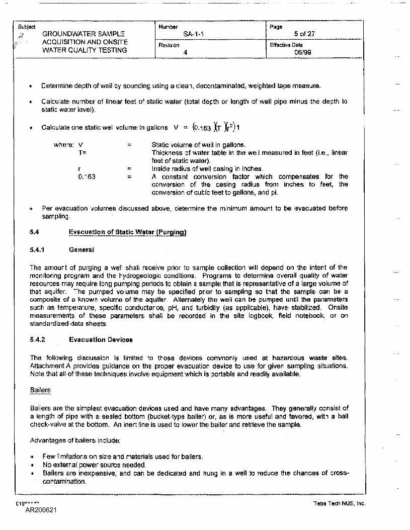
Determine depth of well by sounding using a clean, decontaminated, weighted tape measure.
Calculate number of linear feet of static water (total depth or length of well pipe minus the depth tostatic v/ater level).
Calculate one static well volume in gallons V = '(0.1133 |T |r:!!j'l
where: V'"!"•••
r0.163
Stalk: volume of well in gallons.Thickness of water table in the well measured in feet (i.e., linearfeet of static 'water).Inside radius of well rasing in indues.A constant conversion factor which compensates loir theconversion of the raising radius torn inches to feet, 'theconversion of cubic feet to gallons, and pi.
F:'er evacuation volume!) discussed above determine the rninirnurn amount to be evacuated beforesampling.
5.4
5.4/1 General
The amount of purging a well shall receive prior to sample collection will depend on the intent of themonitoring program and the hyciirogeologic conditions. Programs to determine overall quality of waterresources may require long pumping periods to obtain a sample that: is representative of a large volume ofthat aquifer. The pumped volume may be specified prior to sampling so that the sample can be acomposite ol a known volume of the aquifer, Alternately the well can be pumped until the parameterssuch as temperature, specific conductance, pH, and turbidity (as applicable), have stabilised Onsitemeasurements of these parameters shall be recorded in the site logbook, field notebook, or onstain d a ircl ized data sheets .
5.4.2 Evacuation
The following discussion is 'limited to those devices commonly used at hazardous waste sites..Attachment: A provides guidance on the proper evacuation device to use lor given sampling situations.Note that all of theses techniques involve equipment which is portable and readily available.
Bajlers
Bailers are the simplest evacuation devices used and have many advantages. They generally consist ofa length of pipe with a sealed bottom (bucket-type bailer) or, as is more useful and 'favored, with a ballcheck-valve at the bottom. An inert tine is used to lower the bailer and retrieve the sample-.
Advantages of bailers include:
• Few limitation:! on sire and materials used for bailers,• No external power source needed,• Baiters are inexpensive, and can be dedicated and hung in a well to reduce the chances of cross-
contamination.
019611/P TiBtra Tedi NUS. Inc.
SubjectGROUNDWATER SAMPLEACQUISITION AND OIM8ITEWATER QUALITY TESTING
NumberSA-1-1
Revision4
Page6 of 27
Effective Daite06/99
» There is minimal outclassing of volatile organics while the sample is in the bailer,» Bailers are relatively easy to decontaminate.
Limitations on the use of bailers include the following:
» It: is time consuming to remove stagnant water using a bailer,« Transfer of sample may cause aeration.» Use of bailers is physically demanding, especially in warm temperatures at; protection levels above
Level ID.
Suction_f^jmp_s
There are many different types of inexpensive suction pumps including centrifugal, diaphragm, andperistaltic pumps. Centrifugal and diaphragm pumps; can be used for well evacuation at a fast pumpingrate and for sampling at a low pumping rate. The peristaltic pump is a low volume pump that uses rollersto squeeze a 'flexible tubing, thereby creating suction. This tubing can be dedicated to a well to preventcross contamination.
These pumps are all portable, inexpensive and readily available, However, because they are based onsuction, their use is restricted to areas with water levels within 20 to 25 feet of the ground surface. Asignificant limitation is that: the vacuum created by these pumps can cause significant loss of dissolvedgases and volatile organic®.
AJr^LjftSarnpJerB
This group of pump samplers uses gas pressure either in the annulus of the well or in a venturi to forcethe water up a sampling tube.. These pumps are also relatively inexpensive. Air (or gas)-lift samplers aremore suitable lor well development than for sampling because the samples may be aerated, leading to pHchanges and subsequent: trace metal precipitation, or loss of volatile organics.
Submersible Pumps
Submersible pumps take in water and push the sample up a sample tube to the surface. The powersources for these samplers may be compressed gas or electricity. The operation principles vary and thedisplacement of the sample can be by an inflatable bladder, sliding piston, gas bubble, or impeller.Pumps are available for 2-inch-diameter wells and larger. These pumps; can lift water from considerabledepths {several hundred feet).
Limitations; of this class of pumps include:
• They may have low delivery rates,••' Many models of these pumps are expensive.• Compressed gas or electric power is needed.«> Sediment in 'water may cause clogging of the valves or eroding the impellers with some of these
pumps.<» Decontamination of internal components can be difficult: and time-consuming.
019611/P Tetra Tech NUS, Inc.
Subjectv GROUNDWATER SAM RLE
,;'-;" . ACQUISITION AMD ONSITEIs ' • WATER QUALITY TESTING
NumberSA-1-1
Revision4
Page7 of 27
Effective Date06/99
5 •5
This section describes the procedures and equipment required to measure the following parameters of anaqueous; sample in the field:
pHSpecific ConductanceTemperatureDissolved Oxygen (DO1)Oxidation Reduction Potential (OIRP)Certain Dissolved Constituents Using Specific Ion ElementsTurbiditySalinity
This section is applicable for use in an onsite groundwater quality monitoring program to be conducted at:3 hazardous; or nonhazardous site. The procedures; and equipment: described are applicable togroundwater samples; and ara not, in general, subject: to solution interferences; from color, tuirbidiity, andcolloidal material or suspended matter.
This section provides general information four measuring the para meters listed above with instruments andtechniques in common use. Since instruments from different manufacturers may vary, review of themanufacturer's literature pertaining to the use of a specific instrument: is required before use.
5.5.1 Measi uireriiieiiil: of pH
5.5.1.1 General
Measurennent of pM is one of the most important arid frequently used tests in water chemistry. Practicallyevery phase of water supply and wastewater treatment such as; acid-base neutralization, waiter softening,and corrosion control is pH dependent. Likewise, the pH of leachate can be correlated with otherchemical analyses to deter mine the probable source of contamination, It is therefore important thatreasonably accurate pH measurement:! be taken.
Two methods are given for pH measurement: the pH meter and pH indicator paper. The indicator paperis used when only a rough estimate of the pH is required, and the pH meter when a moire accuratemeasurement: is needed. The response of a pH meter can be affected to a slight degree by high levels ofcolloidal or suspended solids, but the effect is usually small and generally of little significance.Consequently, specific methods to overcome this interference are not described. The response of pHpaper is unaffected by solution interferences from color, turbidity, colloidal or suspended material!! unlessextremely high levels capable of coating or masking the paper are encountered. In such cases, use of apH meter is recommended.
5.5.1.2
Use of pH papers for pH measurement relies on a chemical reaction caused by the acidity or alkalinity ofthe solution created by the addition of the water sample reacting with the indicator compound on thepaper. Various types of pH papers are available, including litmus (for general acidity or alkalinitydetermination) and specific pH range hydrion paper.
019511/P Tetra Tech NUS, Uric.
SubjectGROUNDWATER SAMPLEACQUISITION AND ONSITE
. WATER QUALITY TESTING
Number8A-1-1
Revision4
Page8 of 27
Effective Date)06/99
Use of a pH meter relies on the same principle as other ion-specific electrodes, Measurement relies onestablishment of a potential difference across a glass or other type of membrane in response to (in thisinstance, hydrogen) ion concentration across that membrane. The membrane is conductive to ionicspecies and, in combination with a standard or reference electrode, a potential difference proportional tothe ion concentration is generated and measured.
5.5.1.3 IjEgujjarnent
The following equipment is needed for taking pH measurements:
« Stand-alone portable pH meter, or combination meter (e.g., Horiba U-10), or combination meterequipped with an in-line sample chamber (e.g., YSI 610).
« Combination electrode with polymer body to Jit the above meter (alternately a pH electrode and areference electrode can be used if the pH meter is equipped with suitable electrode inputs).
« Buffer solutions, as specified, by the manufacturer.
« pH indicator paper, to cover the pH range 2 through 12.
« Manufacturer's operation manual.
5.5.1.4 Measurement Technjgues for Field Determination of pH
pH Meter
The following procedure is used for measuring pH with si pH meter (meter standardization is according tomanufacturer's instructions):
» Inspect the instrument and batteries prior to initiation of the field effort.
» Check the integrity of the buffer solutions used for field calibration. Buffer solutions need to bechanged often as a result of degradation upon exposure to the atmosphere.
i> If applicable, make sure all electrolyte solutions within the electrode(s) are at their proper levels andthat no air bubbles are present within the electrodes).
» Calibrate on si daily use basis (or as recommended by manufacturer) following manufacturer'sinstructions. Record calibration data on an equipment calibration log sheet
» Immerse Hie electirode(s) in the sample, slowly stirring the probe until the pM stabilizes. Stabilizationmay take several seconds to minutes. If the pH continues to drift, the sample temperature may not bestable, a physical reaction (e.g., degassing) may be taking place in the sample, or the meter orelectrode may be malfunctioning. This must be clearly noted in the logbook.
• Read and record the pH of the sample. pH shall be recorded to the nearest 0.01 pH unit. Also recordthe sample temperature.
<> Rinse the electrode(s) with deionized water.
» Store the electrode(s) in an appropriate manner when not in use.
019611 IP Tetra Tech INIUS, Inc.
SubjectGROUNDWATERSAMPLE
,,! ACQUISITION AND OMSITE0^ ' ' WATER QUALITY TESTING
NuniterSA-1-1
Revision4
Page9 of 27
Effective Date06/99
Any visual observation of conditions which may interfere with pM measurement, such as oily materials, orturbidity, shall be noted.
plH Paper
Use of pM paper is very simple and requires no sample preparation, standardization, etc. pH paper isavailable in several ranges, including wide-range (indicating approximately pH 1 to 12), mid-range(approximately pH Q to 6, 6 to 9, 3 to 114) and narrow-range (many available, 'with ranges as narrow as1.5 pH units). The appropriate range of pH paper shall be selected, If the pH is unknown theinvestigation shall start with wide-range paper and proceed with successively narrower range paper untilthe sample pl-i is adequately determined.
5.5.2 Measurement off 'Specific Conductance
5.5.2.1 General
Conductance provides; a measure of dissolved ionic species in water and can b€ used to identity thedirection and extent of migration of contaminants in groundwater or surface water. II: can also be used asa measure of subsurface biodegradation or to indicate alternate sources of ground water contamination.
Conductivity is a numerical expression of the ability of a water sample to cany an electric current Thisvalue depends on the total concentration of the ionized! substances dissolved in the water and thetemperature at which the measurement is made. The mobility of each of the various dissolved ions, theirvalences, and their actual and relative concentrations affect conductivity.
It is important to obtain a specific conductance measurement soon after taking a sample, sincetemperature changes, precipitation reactions, and absorption of carbon dioxide from line air all affect thes pecif ic con d uctance .
5.5.2.2 r C p t e s j f I i i j i
An aqueous system containing ions will! conduct an electric; current In a direct-current field, the positiveions migrate toward the negative electrode, while the negatively charged ions migrate toward the positive:electrode. Most inorganic adds, bases and sails (such as hydrochloric acid, sodium carbonate, or sodiumchloride, respectively) are relatively good conductors. Conversely, organic compounds such as sucroseor benzene, which do not dissociate in aqueous solution, conduct a current very poorly, if at all.
A conductance cell and a Wheatetone Bridge (for the measurement of potential difference) may be usedfor measurement of electrical resistance. The ratio of current applied to voltage across the cell may alsobe used as a measure of conductance. The core element of the apparatus is the conductivity cellcontaining the solution of interest. Depending on ionic strength of (tie aqueous solution ID be tested, apotential difference is developed across the cell which can be converted directly or indirectly (dependingon instrument type) to a measurement of specific conductance.
0196111P Tetra Tech NUS, Inc.
SubjectGROUNDWATER SAMPLEACQUISITION AND ONSITEWATER QUALITY TESTING
NumberSA-1-1
Revision4
Page10 of 27
Effective Dale06/99
5.5.2.3 Eguigment
The following equipment is needled for taking specific conductance (SC) measurements:
• Stand alone portable conductivity meter, or combination meter (e.g., Horiba LI-10), or combinationmeter equipped with an in-line sample chamber (e.g., YSI 610).
• Calibration solution, as specified by the manufacturer,• Manufacturer's; operation manual.
A variety of conductivity meters are available which rnay also be used to monitor salinity, and tennperature.Probe types and cable lengths vary, so equip men): must be obtained to rued: the specific requirement: ofthe sampling program.
5.5,2.4
The steps involved in taking specific conductance measurements are listed below (standardization isaccording to manufacturer's instructions):
« Check batteries and calibrate instrument before going into the field.
» Calibrate on a daily use basis (or as recommended by manufacturer), according to the manufacturer'sinstructions and record all pertinent: information on an equipment calibration log sheet. Potassiumchloride solutions with a SC closest to the values expected in the field shall be used for calibration.Attachment IB provides guidance in this regard.
» Rinse the eel I with one or more portions of the sample to be tested or with deionized water.
» Immerse the electrode in the sample and measure the conductivity. Adjust the temperature setting tothe sample temperature (if applicable).
•> Read and record the results in a field logbook or sample log sheet.
• Rinse the electrode with deionized water.
If the specific conductance measurements become erratic, recalibrate the instrument and see themanufacturer's instructions for details.
5.5.3 Measurement of Temperature
5.5.3.1 Genera]
In combination with other parameters, temperature can be a useful indicator of the likelihood of biologicalaction in a water sample. It can also be used to trace the flow direction of contaminated groundwater.Temperature measurements shall be taken in-situ, or as quickly as possible in the field. Collected watersamples may rapidly equilibrate with the temperature of their surroundings.
5.5.3.2 Egujament
Temperature measurements may be taken with alcohol-toluene, mercury lilted or dial-type thermometer;;,In addition, various meters such as specific conductance or dissolved oxygen meters, which have
\
019611/P Tetra Tech NUS, Inc.
Subject?f GROUNDWATER SAMPLE
;>' • -• ACQUISITION AMD OIMSITE: WATER QUALITY TESTING
NumberSA-1-1
Revision4
Page1110127
Effective Diafe06/99
temperature measurement capabilities, may also be used. Using such instrumentation siloing with suitableprobes and cables, in-situ measurements oltennperalure at great: depths can be performed.
5.5.3,3 Measurement Techjiigues ^r_WjterJerngerature
If a thermometer is used to determine the ternperature for a water sample:
» Immerse the thermometer in the sample until temperature equilibrium is obtained (1-3 minutes). Toavoid the possibility of cross-contamination, the thermometer shall not be inserted into samples whichwill undergo subsequent chemical analysis.
« Record values in a field logbook or sample log sheet
If a temperature meter or probe is used, the instrument shall be calibrated according to manufacturer'srecommendations.
5.5,4 WleiisiurenrKiini! of Dissolved Oxygen
5.5.4.1 General
Dissolved oxygen (DO) levels in natural water and wastewater depend on the physical, chemical andbiochemical activities in the water body. Conversely, the growth of many aquatic organisms as well astine rale of corrosivity, are dependent on the dissolved oxygen concentration. Thus, analysis lor dissolvedoxygen is a key test in waiter pollution and waste treatment process control. If at: all possible, DOmeasurements shall be taken in-situ, since concentration may show a large change in a short time if thesample is not adequately preserved.
The monitoring method discussed herein is limited to the use of dissolved oxygen meters only. Chemicalmethods of analysis, (i.e., Winkler methods) are available, but require rnoire equipment and greater samplemanipulation. Furthermore, DO meters, using a membrane electrode, are suitable for highly pollutedwaters, because the probe is completely submersible, and is not susceptible to interference caused bycolor, turbidity, colloidal material or suspended matter.
5.5.4.2 Prjncipjes of Equjpjnent Operation
Dissolved oxygen probes are normally electrochemical cells that have two solid metal electrodes ofdifferent nobility immersed in an electrolyte. line electrolyte is retained by an oxygen-permeablemembrane. The metal of highest nobility (the cathode) is positioned1 at the membrane. When a suitablepotential exists between the two metals, ireduction of oxygen to hydroxide ion (OH") occurs at: the cathodesurface. An electrical current is developed that is directly proportional to the rate of arrival of oxygenmolecules at: the cathode.
Since 'the current produced in the probe is directly proportional to the rate of arrival of oxygen at thecathode, it is important that a fresh supply of sample always be in contact with the membrane. Otherwise,the oxygen in the aqueous layer along the membrane is quickly depleted and false tow reading;; areobtained, lit is therefore necessary to stir (tie sample (or the probe) constantly to maintain fresh solutionnear the membrane interface. Stirring, however, shall not be so vigorous that additional oxygen isintroduced through the air-water interface at the sannple surface. To avoid this possibility, some probesare equipped with slirreirs to agitate the solution near the probe, while leaving the surface of the solutionundisturbed.
019611/P Tetra Tech IMUS, Inc.
SubjectGROUNDWATERSAMPLEACQUISITION AND ONSITEWATER QUALITY TESTING
NumberSA-1-1
Revision4
Page12 of 27
Effective Date06/99
Dissolved oxygen probes sire relatively unaffected by interference-;. Interferences that can occur arereactions with oxidizing gases (such as chlorine) or with gases such as hydrogen sulfide, which are noteasily depolarized from the indicating electrode, If a gaseous interference is suspected, it shall be notedin the field log book and checked if possible. Temperature variation?; can also cause interferencebecause probes exhibit temperature sensitivity. Automatic temperature compensation is normallyprovided by the manufacturer.
5,5.4,3 Egujpment
The following equipment is needed to measure dissolved oxygen concentration :
•> Stand alone portable dissolved oxygen rneter, or combination meter (e.g., Hoiriba IJ-10), orcombination meter equipped with an in-line sample chamber (e.g., YSI 610).
• Sufficient cable to allow the probe to contact the sample.• Manufacturer's operation manual.
5.5.4.4 Detejirjinatjon
Probes differ as to specifics of use. Follow the manufacturer's instructions to obtain an accurate reading,The following general steps shall be used to measure the dissolved oxygen concentration:
• The equipment shall be calibrated and have its batteries checked before going to the field.
• The probe shall be conditioned in a water sample for as long a period as practical before use in thefield. Long periods of dry storage followed by short periods of use in the field may result in inaccuratereadings.
• The instrument shall be calibrated in the field according to manufacturer's recommendations or in afreshly air-saturated water sample of known temperature. Dissolved oxygen values for air-saturatedwater can be determined by consulting a table listing oxygen solubilities as a function of temperatureand salinity (see Attachment C).
• Record all pertinent information on an equipment calibration sheet
<» Rinse the probe with deionized water.
'« • Immense the probe in the sample. Be sure to provide for sufficient flow past the membrane by stirringthe sample. Probes without stirrers placed in wells can be moved up and down.
« Record the dissolved oxygen content and temperature of the sample in a field logbook or sample logsheet.
« Rinse the probe with deionized water.
« Recalibrate the probe when the membrane is replaced, or as needed. Follow the manufacturer'sinstructions,
01961 Iff" Telia Tech NUS, Inc.
Subject•^ GROUNDWATER SAMPLE
v ACQUISITION AND OIMSITEWATER QUALITY TESTING
NumberSA-1-1
Revision4
Page
13 of 27Effective Qijgrto
06/99
Note that: in-situ placement of the probe is preferable, since sample handling is not: involved. Thishowever, rnay not always be practical. IBe sure to record whether the liquid was analyzed in-situi, or if asample was taken.
Special care shall be taken during sample collection to avoid turbulence which can lead to increasedoxygen solubilization and positive test: interferences.
5.5.5 Mean uiriEiniH nil: of Oxidation-Reduction Potential
5.5.5.1 General
The oxidation-reduction potential (ORP) provides a measure of the tendency of organic or inorganiccompounds to exist in an oxidized state. The ORP parameter therefore provides evidence of thelikelihood of anaerobic degradation of biodegradable organios or the ratio of activities of oxidized toreduced species in the sample.
5.5.5.2
When an inert: metal electrode, such as platinum, is iimnnairsedl in a solution, B potential is developed atthai: electrode depending on the ions present in the solution. If a reference electrode is placed in thesame solution, an ORP electrode pair is established. This electrode pair allows the potential differencebetween the two electrodes to te measured and is dependent on the concentration of the ions in solution.By this measurement, the ability to oxidize or reduce species in solution may be determined.Supplemental measurernents, such as dissolved oxygen, may be correlated with ORP to provide aknowledge of the quality of the solution, water, or wastewater.
5.5.5.3 EgulpjTjent
The following equipment is needed for measuring the oxidation-reduction potential ol a solution:
Portable pH meter or equivalent, with a millivolt: scale.Platinum electrode to fit above pH meter.Reference electrode such as a calomel, silver-silver chloride, or equivalent.Reference solution as specified by the manufacturer,Manufacturer's operation manual.
5.5.5.4 M!=:i=['MM^
The following procedure is used for measuring oxidation-reduction potential:
« The equipment shall be calibrated and have its batteries checked before going to the 'field.
» Check that: the platinum probe is clean and that the platinum bond or tip is unoxidized. If dirty, polishwith emery paper or, if necessary, clean the electrode using aqua iregia, nitric acid, or chromic acid, inaccordance with manufacturer's instructions.
« Thoroughly rinse the electrode with deionized water.
• Verify the sensitivity of the electrodes by noting the change in millivolt: reading when the pH of the test:solution is altered. The ORP will increase when the pH of the test solution decreases, and the ORP
018611/P Tetra Tech NUS, Inc.
SubjectGROUNDWATER SAMPLEACQUISITION AND ONSITEWATER QUALITY TESTING
NumberSA-1-1
Revision4
Page14 of 27
Effective Date06/99
will decrease if the test solution pH is increased. Place the sample in a clean container and agitatethe sample. Insert the electrodes and note the ORP drops sharply when the caustic is added (i.e., pHis raised) thus indicating the electrodes are sensitive and operating properly. If the ORP increasessharply when the caustic is added, the polarily is reversed and must be corrected in accordance withthe manufacturer's instructions. If the ORP does not respond as above when the caustic is added,the electrodes shall be cleaned and the above procedure repeated.
• After the assembly1 has been checked for sensitivity, wash the electrodes with three changes of wateror by means of a flowing stream of deionized water from a wash bottle. Place the sample in a cleancontainer and insert the electrodes, Set temperature compensator throughout the measurementperiod. Read the millivolt potential of the solution, allowing sufficient time for the system to stabilizeand reach temperature equilibrium. Measure successive portions of the sample until readings on twosuccessive portions differ by no more than 10 rnV. A system that is very slow to stabilize properly willnot yield a meaningful ORP. Record all results in a field logbook or sample logsheet, including ORP(to nearest 10 mV), sample temperature and pH at the time of measurement.
5,5.6 Measurement of Turbidity
5.5.6.1 General
Turbidity is an expression of the optical properly that causes light to be scattered and absorbed ratherthan transmitted in a straight line through the sample. Turbidity in water is caused by suspended matter,such as clay, silt, finely divided organic and inorganic matter, soluble colored organic compounds, andmicroscopic organisms, including plankton.
It is important to obtain a turbidity reading immediately alter taking a sample, since irreversible changes inturbidity may occur if the sample is stored too long.
5.5.6.2 Pjincipjes of Egujgment Operation
Turbidity is measured by the Nephelometric Method. This method is based on a comparison of theintensity of light scattered by the sample under defined conditions with the intensity of light scattered by astandard reference suspension under 'the same conditions. The higher the scattered light intensity, thehigher the turbidity,
Forrnazin polymer is used as 'the reference turbidity standard suspension because of its ease ofpreparation combined with a higher reproclucibility of its light-scattering properties than clay or turbidnatural water. The turbidity of a specified concentration of formazin suspension is defined as 40nephelometric units.. This same suspension has an approximate turbidity of 40 Jackson units whenmeasured on the candle turbidimeter. Therefore, nephelometric turbidity units (NTU) based on theforma;::in preparation will approximate units derived from the candle turbidimeter but will not be identical tothem.
5.5.6.3 EquJEn^G!
The following equipment is needed for turbidity measurement:
«» Stand alone portable turbidity meter, or combination meter (e.g., Horiba IJ-10), or combination meterequipped with an in-line sample chamber (e.g., YSI61).
019611/P Tetra Tech WUS, Inc.
--;:(<! ———————————————————————————————.vStibjectf •<-' ' GROUNDWATER SAMPLE
ACQUISITION AND ONSITE;WATER QUALITY TESTING
NumberSA-1-1
Rwiision4
PagoIS of 27
[Effective CMo06/90
« Calibration solution, as specified by the manufacturer. •
« Manufacturer's operation manual.
5,5.6.4 Measurement Techniques for Turbidity
The steps involved in taking turbidity measurements are listed below (standardization is according tomanufacturer's instructions):
" Check batteries; and calibrate instrument before going- into the 'field,
• Check the expiration date (etc.) of the solutions used for field calibration.
« Calibrate on a daily use basis, according to the manufacturer's instructions and record all pertinentinformation on an equipment calibration log sheet.
<i> Rinse the cell with one or more portions of the sample to be tested or 'with deionized waiter.
» I immerse the probe in the sample and measure the turbidity, The reading must toe taken irnrnediatelyas suspended solids will settle over time resulting in a lower, inaccurate turbidity reading.
« Read and record the results in a field logbook or sample log sheet. Include a physical description ofthe sample, including color, qualitative estimate of turbidity, etc..
• Rinse the electrode with deionized water.
5.5.7 MiEtasurameirilt of Salinity
5.5.7.1 General
Salinity is a unitless properly of industrial and natural waters. Ill is the measurement of dissolved salts in agiven mass of solution. Note: Most: field meters determined salinity autornatically from conductivity andtemperature. The displayed value will be displayed in either parts per thousand (ppt) or % (e.g., 35 pptwill equal 3.5%).
5.5.7.2 Principles of Ecjuigment Operation
Salinity is determined autornatically from the meter's conductivity and temperature read!ings according toalgorithm!:; (found in Standard methods forth® Examination of Water and Wastewatei). Depending on themeter,, the results are displayed in either ppt or %. The salinity measurements are carried out: in referenceto the conductivity of standard seawater (corrected to S= 35).
5.5.7.3 Eguigrnent
The following equipment: is needed for Salinity measurements:
« Multi-parameter water quality meter capable of measuring conductive, temperature and convertingthem to salinity (e.g., Horiba U-10 or YSI610).LIKSIIII u.i :»:nn uiy \ <::.;.(., MUIIIMCI i.r- M.F ui n on u iiuji.
Calibration Solution, as specified by the manufacturer.Manufacturer's operation manual.
019611/P Tetra Tech NUS, Inc.
SubjectGROUNDWATER SAMPLEACQUISITION AND ONSITEWATER QUALITY TESTING
NumberSA-1-1
Revision4
Pago16 Of 27
Effective Date.06/99
5 . 5.7 .4 Measurement Tech niiq yes for Sain ity
The steps involved in taking Salinity measurements are listed bellow (standardization is according tomanufacturer's instructions):
• Check batteries and calibrate before going into the field.
• Check the expiration date (etc.) of the solutions used for field calibration.
• Calibrate on a daily use basis, according to the manufacturer's instructions and record all pertinentinformation on an equipment calibration log sheet.
« Rinse the cell with the sample to be tested.
• Immerse the probes In the sample and measure the salinity. Read and record the results in a fieldlogbook or sample log sheet.
» Rinse the probes with deionized water.
5.6
5.6.1 Sampling Plan
The sampling approach consisting of the following, shall be developed as part of the project plaindocuments which are a p proved prior to beginning work in the field:
« Background and objectives of sampling.
« Brief description of area and 'waste characterisation.
» Identification of sampling locations, with map or sketch, and applicable well construction data (wellsize, depth, screened interval, reference elevation).
• Intended number, sequence volumes, and types of samples. If the relative degrees of contaminationbetween wells is unknown or insignificant, a sampling sequence which lacilitates sampling logistics;may be followed. Where some wells are known or strongly suspected of being highly contaminated,these shall be sampled last to reduce the risk of cross-contamination be 'tween wells as a result of thesampling procedures.
« Sample preservation requirements.
« Work; schedule.
» List of team members.
» List; of observers and contacts.
» Other information, such as the necessity for a warrant or pernnission of entry, requirement for splitsamples, access problems, location of keys, etc.
019611/P Tetra Tech NUS, Inc.
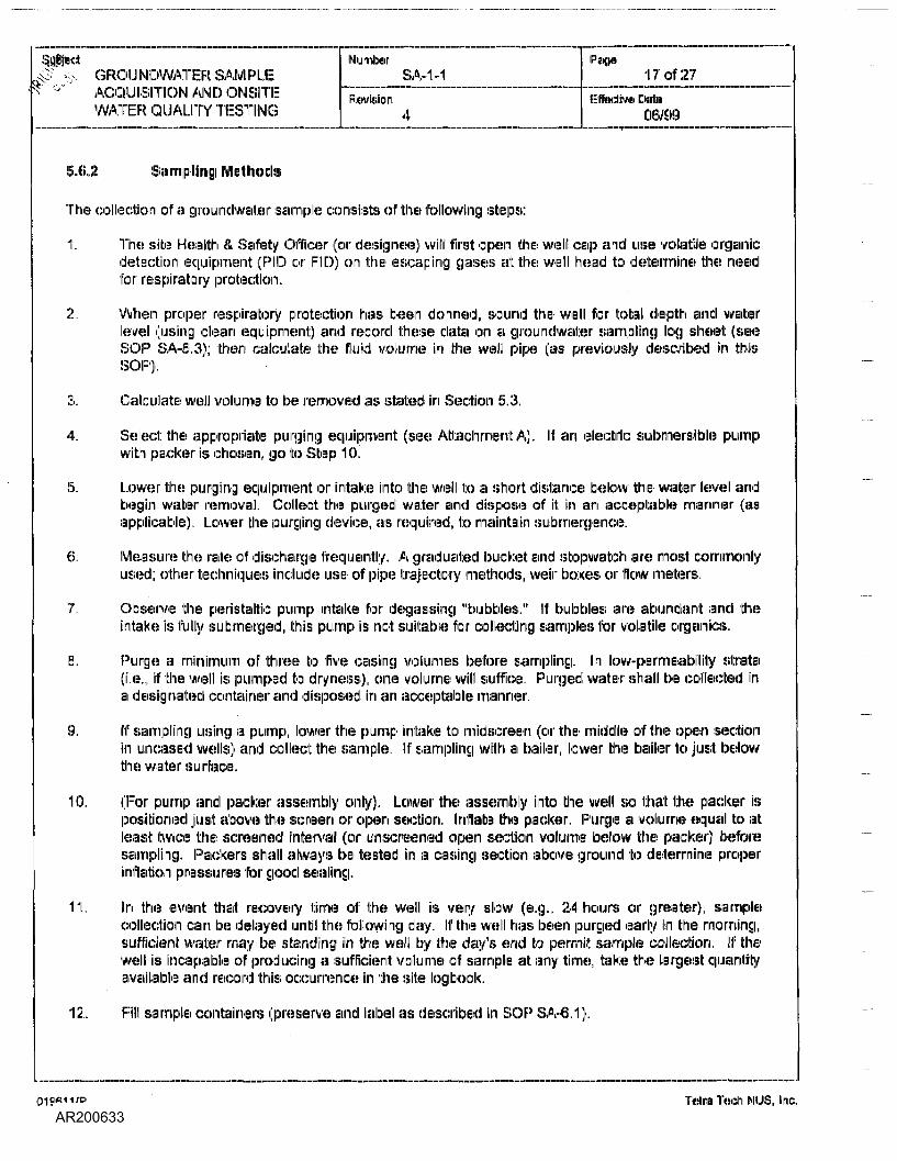
4 ' . GROUNDWATER SAMPLE'• 'J' ACQUISITION AND ONSITE
WATER QUALITY TESTING
NumberSA-1-1
Revision4
Pa(K>17 of 27
EiltedJviii Dateo&/9<;i
. 5.6.2 Saiiiripliiriig IMIullhods
The collection of a groundwater sample consists of the following steps:
1. The site Health & Safety Officer (or designer) will first open the well cap and use volatile organicdetection equipment (PID or FID) on the escaping gases at the well head to determine the needfor respiratory protection.
2. When proper respiratory protection hail been donned, sound the well for total depth and waterlevel (using clean equipment) and record these data on a groundwater sampling log sheet (seeSOP SA-6.3); then calculate the fluid volume in the well pipe (as previously described in this;SOP).
3. Calculate well volume to be removed as stated in Section 5,3.
4. Select: the appropriate purging equipment (see Attachment A). Ill an electric submersible pumpwith packer is chosen, go to 'Step 10,
5. Lower the purging equipment or intake into the well to a short distance bellow line water level andbegin water removal. Collect the purged water and dispose of it: in an acceptable manner (a;,applicable). Lower the purging device, as required, to maintain submergence.
6. Measure the rate of discharge frequently. A graduated bucket: and stopwatch are most: commonlyused; other techniques include use of pipe trajectory methods, weir boxes or flow meters.
7. Observe the peristaltic pump intake for degassing "bubbles." If bubbles are abundant and theintake is fully submerged, this pump is not suitable for collecting samples for volatile organiics.
8. Purge a minimum of three to five casing volumes before sampling. In low-permeability strata(i.e., if the well is pumped to dryness), one volume will suffice. Purged water shall be collected Ina designated container and disposed in am acceptable manner.
9. If sampling using a pump, lower the pump intake to midscreen (or the middle of the open sectionin uncased wells) and collet;': the sample. If sampling with a bailer, lower the bailer to just belowthe water surface.
10. (For pump and packer assembly only). Lower the assembly into the well so that the packer ispositioned just above the screen or open section. Inflate the packer. Purge a volume equal to at:least: twice the screened interval (or unscreened open section volume bellow the packer) beforesampling. Packers shall always be tested in a casing section above ground to determine properinflation pressures for good sealing.
11. In the event that recovery time of the well is very slow (e.g., 24 hours or greater), samplecollection can be delayed until the following day. If the well has been purged early in the morning,sufficient water may be standing in the well by the clay's end to permit sample collection. If thewell is incapable of producing a sufficient volume of sample at any time, take the largest quantityavailable and record this occurrence in the site logbook.
12. Fill sample containers (preserve and label as described in SOP SA-6.1).
019611/P Tffltna Tech NUS, Inc.
SubjectGROUNDWATER SAMPLEACQUISITION AND ONSITEWATER QUALITY TESTING
NumberSA-1-1
Revision4
Page18 of 27
Effective Date06/99
13. Replace the well cap and lock as appropriate, Make sure the well is readily identifiable as thesource of the samples.
14. Process sample containers as described in SOP SA-6.1.
15. Decontaminate equipment as described in SOP SA-7.1.
5.7 (* ' '
5.7.1 Scopisi fli Application
Low flow purging and sampling techniques are sometimes required for groundwater sampling activities.The purpose of low How purging and sampling is to collect groundwater samples that contain"representative" amounts of mobile organic and inorganic constituents in the vicinity of the selected openwell interval, at near natural flow conditions. The minimum stress procedure emphasizes negligible waterlevel drawdown and low pumping rates in order to collect samples with minimal alterations in waterchemistry. This procedure is designed primarily to be used in wells 'with a casing dia meter of 2 inches ormore and a saturated! screen, or open interval, length of ten feet or less. Samples obtained are suitablefor analyses of coirnnnoin types of groundwater contaminants (volatile and semi-volatile organiccompounds, pesticides, PCBs, metals and other inorganic; ions [cyanide, chloride, sulfate, etc.]). Thisprocedure is not designed to collect non-aqueous phase liquids samples from wells containing light ordense non-aqueous phase liquids (LIMAPLs or DIMAPLs), using the low flow pumps.
The procedure is flexible for various well construction types and groundwater yields. The goal of theprocedure is to obtain a turbidity level of less than 5 IMTU and to achieve a water level drawdown of lessthan 0.3 feet during purging and sampling. If these goals cannot be achieved, sample collection can takeplace provided the remaining criteria in this procedure are met.
6.7,,2 Equipment
The following equipment is required (as applicable) for lew flow purging and sampling:
« Adjustable rate, submersible pump (e.g., centrifugal; or bladder pump constructed of stainless steel orTeflon).
<• Disposable clear plastic bottom filling bailers rnay be used to check for and obtain samples of LNAPILsor DNAIPLs,
» Tubing - Teflon, Teflon-lined polyethylene, polyethylene, PVC, Tygon, stainless steel tubing can beused to collect samples for analysis, depending on the analyses to be performed and regulatoryrequirements.
• Water level measuring device, 0.01 foot; accuracy, (electronic devices are preferred for tracking waterlevel drawdown during all pumping operations}.
• Flow measurement supplies.
<" Interface probe, if needed.
01961 Iff' Tetra Tech NUS, Inc.
Suhjisbci-" • • GROUNDWATER SAMPLE
ACQUISITION AND ONSfTEWATER QUALITY TESTING
NumberSA-1-1
Revision[ 4
Page19 of 27
Effective Date06/99
• F:'ower source (generator, nitrogen tank, etc.). If a gasoline generator is used, it must be locateddownwind and at a safe distance from the well so that the exhaust fumes do not contaminate thesamples.
• Indicator parameter monitoring instruments •• pH, turbidity, specific conductance, and temperature.Use of a flow-through cell is recommended. Optional Indicators - ORP and dissolved oxygen, flow-through cell is required. Standards to perform field calibration of instruments.
« {Decontamination supplies.
• Logbook(s), and other forms (e.g., well purging forms).
• Sample Bottles.
<» Sarnple preservation supplies (as required by the analytical methods).
• Sample tags and/or labels.
» Well construction data, location map, field data from last sampling event
» Field Sampling Plan.
« 1PID or FID instrument for measuring VOGs (volatile organic compounds)).
5.7.3 Pi.irgini;i iiincl Sampling Procedure
Use a submersible pump to purge and sample monitoring wells which have a 2.0 inch or greater wellcasing diameter.
Measure and record the water level immediately prior to placing the pump in the well.
Lower purnp, safety cable, tubing and electrical lines slowly into the well so that the pump intake is locatedat the center of the saturated screen length of the well. If possible keep the pump intake at least two feetabove the bottom of the well, to minimize mobilization of sediment that may be present in the bottom o!the well. Collection of turbidity-free water samples may be difficult if there is three feet or less of standingwater in the well..
When starting (tie purnp, slowly increase the pump speed until a discharge occurs. Chert; water level.Adjust purnp speed to maintain little or no water level drawdown. The target draw'doiwn should be lessthan 0.3 feel and it should stabilize. If the 'target of less than 0.3 feet cannot: be achieved or maintained,the sampling is acceptable if remaining criteria in the procedure are met Subsequent sampling roundswill probably have intake settings and extraction rates that are comparable to those used in the initialsampling rounds.
Monitor water level and pumping rate every five to ten minutes (or as appropriate) during purging. Recordpumping rate adjustments end depths to water, Pumping rates should, as needed, be reduced to theminimum capabilities of the pump (e.g., 0.1-0.2 l/rniri) to ensure stabilization of indicator parameters,.Adjustments are best made in the first fifteen minutes of pumping in order to help minimize purgingi time.During initial purnp start-up, drawdown may exceed the 0.5 feel: target and then recover as pump flowadjustments are made (minimum purge volume calculations should utilize stabilised drawdown values, notthe initial drawdown). If the recharge rate of the well! is less than mimmum capability of the pump do not
019611/P Tetra Tech NUS. Inc.
Sub|ectGROUNDWATERSAMPLEACQUISITION AMD OMSITEWATER QUALITY TESTING
Number.SA-1-1 ,
Revision4
Page20 of 27
Effective D'Sitti06/99
allow the water level to fall to the intake level (if the static water level is above the screen, avoid loweringthe water level into the screen). Shut off the pump if either of the above is about to occur and allow thewater level to recover, Repeal: the process; until field indicator parameters stabilise and the minimumpurge volume is removed. The minimum purge volume with negligible drawdown (0.3 feet or less) is twosaturated screen length volumes. In situations where the drawdown is greater than 0.3 feet and hasstabilized, the minimum purge volume is two times the saturated screen volume plus the stabilizeddrawdown volume. After the minimum purge volume is attained (and field parameters have stabilized)begin sampling, For low yields wells, commence sampling as soon as the well has recovered sufficientlyto collect the appropriate volume for all anticipated samples.
During well purging, monitor field indicator parameters (turbidity, temperature, specific conductance. pHI,etc.) every five to ten minutes (or as appropriate). Purging is complete and sampling may begin when allfield indicator jpairarneters have stabilized (variations in values are within ten percent of each other, pH -H-0.2 units, for three consecutive readings taken at: five to ten minute intervals), If the parameters havestabilized, but turbidity remains above 5 IMTLI goal, decrease pump flow irate, and continue measurementof parameters every five to ten minutes. If pumping irate cannot be decreased any further and stabilizedturbidity values remain .above 5 NTU goal record this information. Measurements of field parametersshould be obtained (as per Section 5.5) and recorded.
VOC samples are preferably collected first, directly into pre-preserved sample containers. Fill all samplecontainer!! by allowing the pump discharge to flow gently down the inside of the container with minimalturbulence.
If the water column in the pump tubing collapses (water does not completely fill the tubing) before exitingthe tubing, use one of the following procedures to collect; VOC samples: (1) Collect the non-VOGssamples first, then increase the flow irate incrementally until the water column completely fills the tubing,collect the sample and record the new flow rate; (2) reduce the diameter of the existing tubing until thewater column fills the tubing either by adding a connector (Teflon or stainless steel), or clamp whichshould reduce the flow rate by constricting the end of the tubing; (3) insert a narrow diameter Teflon tubeinto the pump's tubing so that the end of One tubing is in the water column and the other end of the tubingprotrudes beyond the pump's tubing, collect sample from the narrow diameter tubing.
Prepare samples for shipping as per SOP SA-6.1.
6.0 REFERENCES
American Public Health Association, 1989. Standard Methods far the Exa_minatjon of Water andW^stewater, 17th Edition, APHA, Washington, lie"
Barcelona, M. J,, J. IP. Gibb and R. A. Miller, 1983, Ajgujde_tq-the_Selectio_n of_Mater iajs _ fgWjlJ_fJojisJiycJJoji_aji ^ ISWS ContracT Report 327, lilinois "State Water Survey,Champaign, Illinois.
Johnson Division, UOP, Inc. 1975.Industry Johnson Division, UOP, Inc. "Saint
Nielsen, D. M. and G. I... Yeates, 1985. A _ _^ Ground Waiter •Monitoring Review 5: 83-913.
019611/P TetraTachNUS, Inc.
.injectGROUNDWATER SAMPLEACQUISITION AND ONSITEWATER QUALITY TESTING
NumberSA-1-1
IFteviisikin4
Psg&21 of 27
lEilfedivw Dale06/99
Seal!, M. Ft., J. F. McNabb, W. J. Dunlap, R. 1... Crosby and J. Fryberger, 1981.Sannpjing procedures., IR. S. Kerr Environmental Research Laboratory, Office of Research anDewlo rrientrilsrEPA, Ada, .Oklahoma.
U.S. ERA, 1979. M! !!;>!;!:L!<3L! EPA-600/4-79-020.
U.S. EIIPA, 1980. ElPj;:§t l§J ^Office of Solid Waste, United States Environmental Protection .Agency, Washington, D.C,
U.S. EiPA, 1994. §I!;M!<;! !«: U.S.Environmental Protection Agency, Region II.
U.S. Geological Survey, 1984. ljJatjpjiajJ^r]djx>oJ<j3f^Chapiter 5: Chemical and .Physical" Quality, of Waiter an"orl3e7firnent7 U.S. Department of the interior,Reston, Virginia.
019611/P Tetra Tech NUS, Inc.
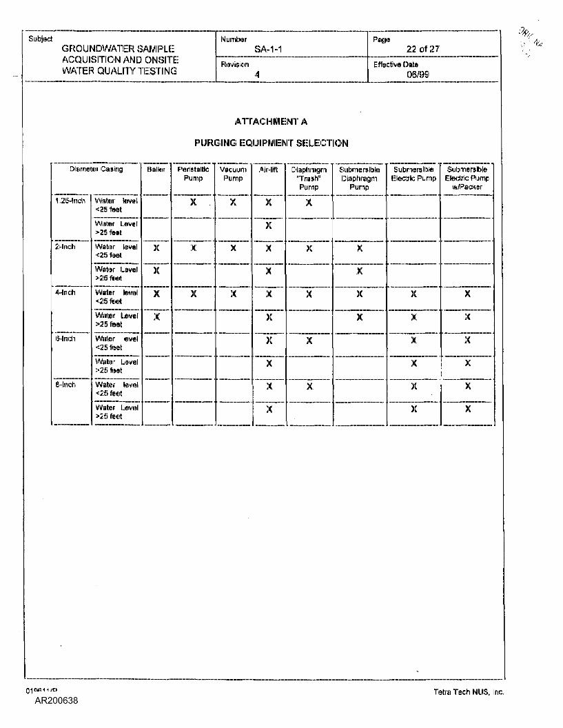
SubjectGROUNDWATER SAMPLEACQUISITION AND ONSITEWATER QUALITY TESTING
NumberSA-1-1
FtevisionA
Proge22 of 27
E:ffed:ivB OntoOB/99
ATTACHMENT A
PURGING EQUIPMENT SELECTION
Diameter Casing
1 .25-Inch
2-Inch
4-Inch
6-Inch
8-Inch
Waiter level<25 feet
Waiter Level>25 footWater tevel<;;>!) feet
Water bevel>;;>!> featWater tetvel<25 feel
Water IjdVHl>25 totWater leveJ<25 feetWater Level>25 feetWater kivel<25 feetWater Lavel>25 feet
E3,=iitor
X
X
X
X
PeilntEittk;Pump
X .
X
X
VacuumPump
X
X
X
Air-lift
X
X
X
X
X
X
X
X
X
X
Diapliiraqiiiri•Trash"Pump
X
X
X
X
X
SubmersibleDiaphragm
Pump
X
X
X
X
SiibnwnsibfcaIE: :iectric Pump
X
X
X
X
X
X
SubmersibleElectric Pump
w/Fadter
X
X
X
X
X
X
0196111 IP Tetra Tech NUS. Inc.
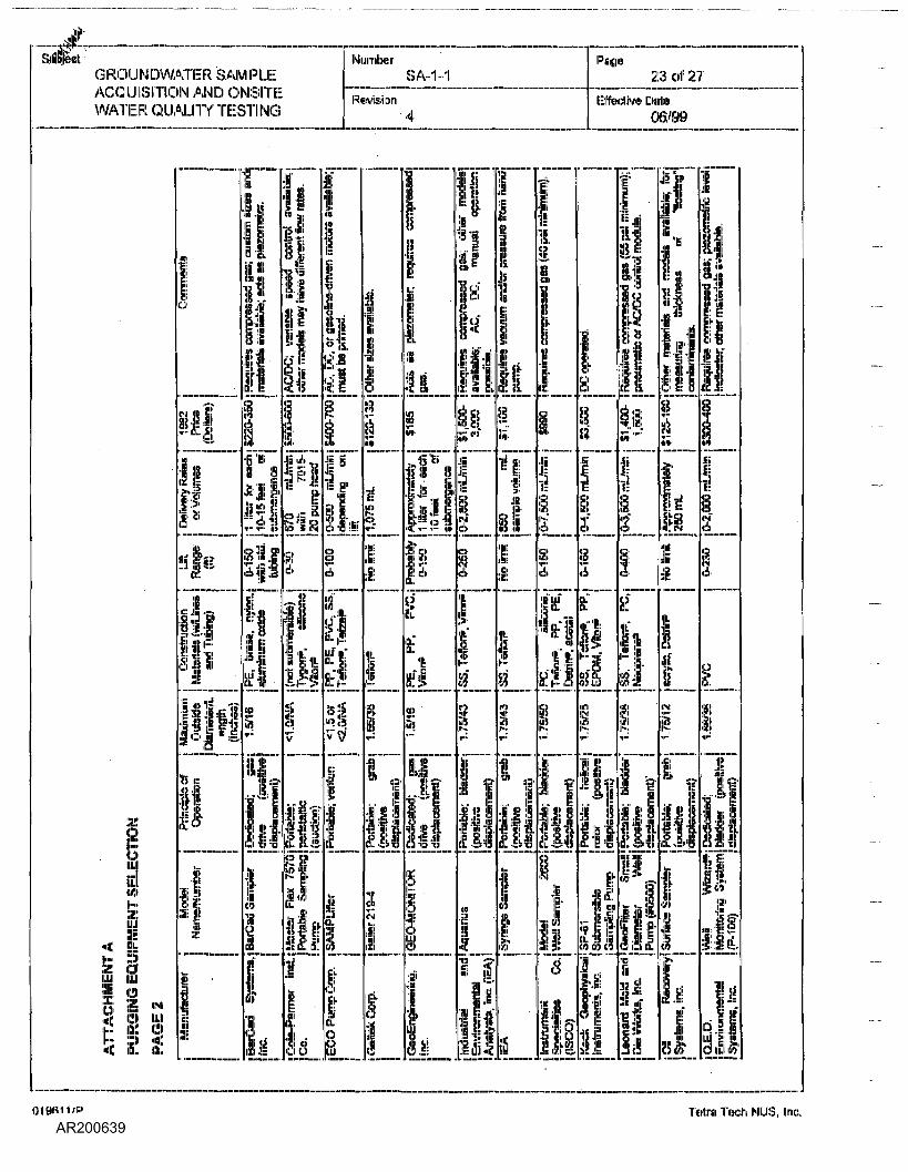
GROUNDWATER SAMPLEACQUISITION AMD OIMSITEWATER QUALITY TESTING
NumberSA-1-1
Revision4
Page23 of 27
Effective Datni06/99
<:;;iU 11.1
2
fire
IMIJLI
ill
oO-
i - io
Iif
tf-l
I
I
I.ii!
'!*-p: o< I- v-
fl
If
ii?
roii <
Ii
I Jill
to
I.!
i!:
I.;
S!:
tft
1I
• >
019611/P Tetra Tech NUS, Inc.
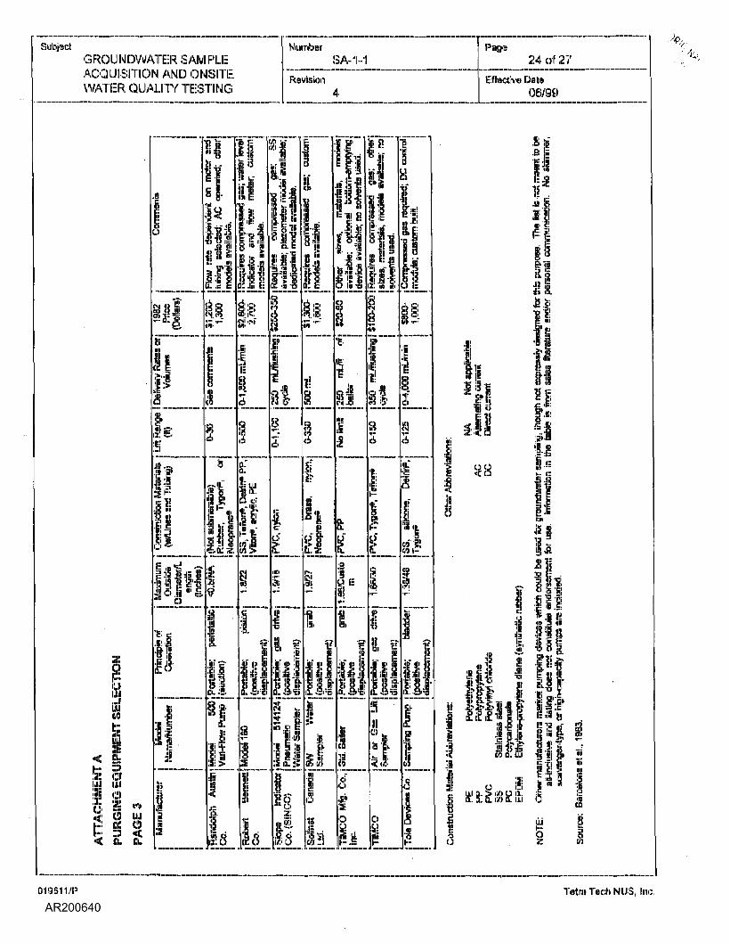
SubjectGROUNDWATER SAMPLEACQUISITION AMD OIMSIITIi-WATER QUALITY TESTING
NumberSA-1-1
Revision
Page24 of 27
Ef fective Date06/99
019611/P Tetra Tech NUS, Inc.
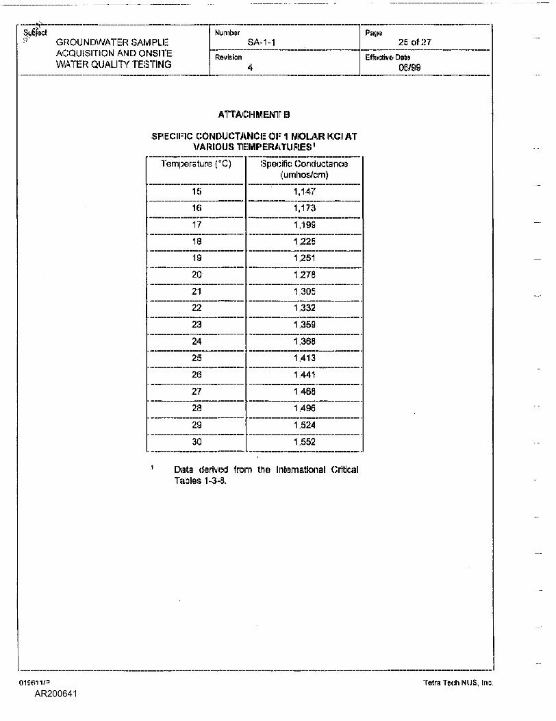
§tfjad^ G ROU IN DWATER SAM RLE
ACQUISITION AND ONSITEWATER QUALITY TESTING
NumberSA-1-1
Revision4
Page2.5 of 27
Effective- Date06/99
ATTACHMENTS
SPECIFIC CONDUCTANCE € I- 1! MOLAR KG) ATVARIOUS TEMPERATURES1
Temperature (°C)
15
16
17
18
19
20
21
22
23
24
25
26
27
28
29
30
Specific Conductance(umhos/cm)
1,1471,173
1,199
1,225
11,251
11,278
1,305
11,332
11,359
1,388
11,413
1,441
1,468
11,498
11,524
11,552
11 DalB derived from the International CriticalTables 1-3-8.
019611/P Tetra Tech NUS, Inc.
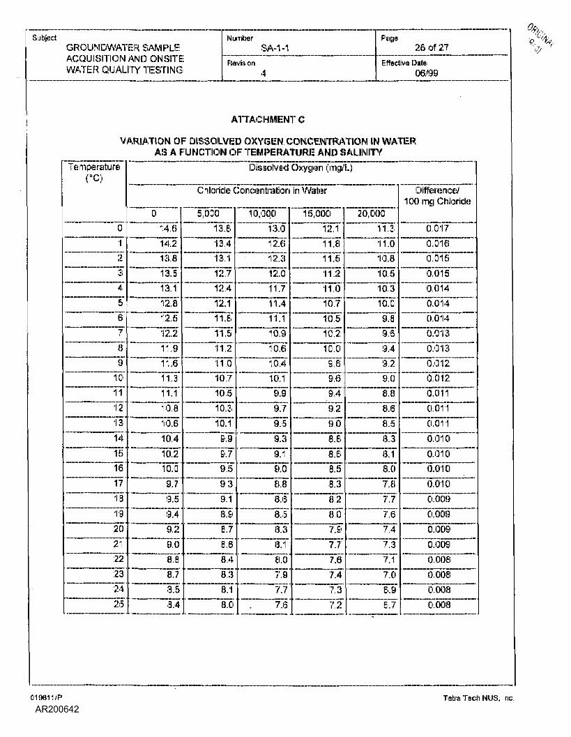
SubjectGROUNDWATER SAMPLEACQUISITION AND ONSITEWATER QUALITY TESTING
Number PageSA-1-1 26 of 27
Revision [Effective Dale4 06/99
ATTACHMENT C
VARIATION OF DISSOLVED OXYGEN CONCENTRATION IN WATERAS A FUNCTION OF TEMPERATURE AND SALINITY
Temperature("C)
0
1234
56
789
10ii1213141516171819202122
232425
Dissolved Oxygen (rrig/L)
Chloride Concentration in Water
014.614.213.8
13.5
13.1
12.812.512.2:11.911.611.311.110.810.6
10.410.210.09.79.5
9.49.29.0
8.88.7
8.58.4
5,00013.813.413.112.712.4
12.111.8
11.511.2
11.010.710.5
10.310.19,99,79.59,39.18,9
8,78,6
8,4
8,38,18,0
10,00013.012.612.312.011.71 1 .4
11.110.910.610.4
10.19.9
9.7
9.5
9.39.19.08.88.68.58.38.18.07.97.77.6
15,00012.1
11.811.511.211.010.710.5
10.210.09.89.69.49,29,08.88.68.58.38.28,07.97.77,6
7.4
7.3
7.2
20,00011.311.010,8
10.510.310.09.89.6
9.49.29.0
3.8
8.68.5
8.38.18.07.87.7
7.67.4
7.37.1
7.08.9
6.7
Difference/'100 ring Chloride
0.0170.0160.015
0.0150.0140.0140.014
0.013
0.0130.0120.0120.011
0.0110.0110.0100.010bVdio0.010Ci.OOEl
0.0090.0090.0090.008
0.0080.008
0.008
019611/P Tetra Tech MUS, Inc.
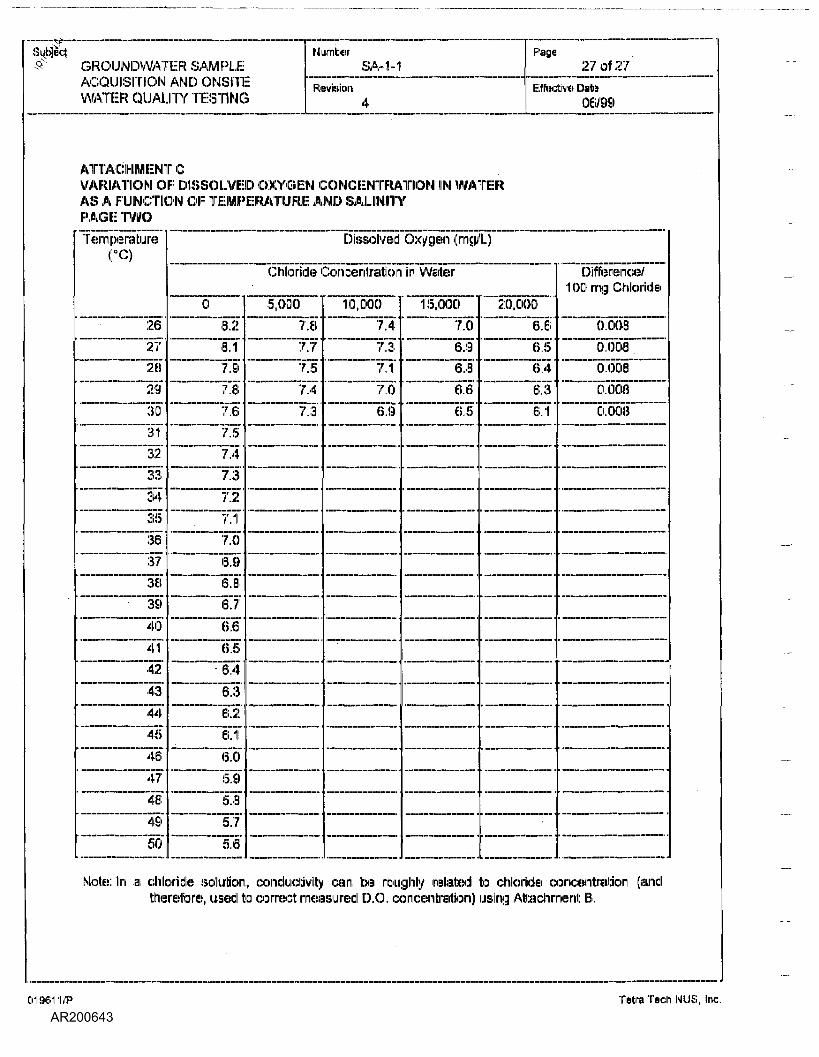
Subject-$' GROUNDWATER SAMPLE
ACQUISITION AND ONSITiWATER QUALITY TESTINC
Number PageSA-1-1 270127
" Revision [Effective Date!i 4 06/99
ATTACHMENT CVARIATION OF DISSOLVED OXYGEN CONCENTRAIIION IN WATEilRAS A FUMCTION OF TEMPERATURE AND SALIINIITYPAGE TWOTemperature
("C)
262728
29
3031
32
333435363738
39404142
4344
454647
4B
49
50
Dissolved Oxygen (rng/L)
Chloride Concenlration in Water
08.28,17,9
7.8
7.67.57.4
7.37.27.17.06.96.36.7
6.66.5
• 6,46.362
6.18.05.95.85.7
5.6
15,000
7.87.77.57.4
7.3
110,0007.47.37.17.06.9
15,0007.06.96.8
8.6
6.5
20,0006.66.56,4
6.36.1 '
Difference/1 00 mg Chloride
0.0080.008 .0.008
0.0080.008
Mote: In a chloride solution, conductivity can, be roughly related to chloride concentration (andtherefore, used to corned: measured D.O, concentration) using Attachment B.
019611/P TetraTech NUS, Inc.
II-TETF
1'' 'llItk ,,
IA TI;:CH NUS, IIMC.
STANDARDOPERATING
PROCEDURES
1 SubjectAIR MONITORING AND SAMPLING
NumberSA-2.2
Ef fecdve Dfftf)03/01/96
Page1 of 8
Revision0
ApplicabilityTetra Tech IMLIS, Inc.
Prepar&dEarth Sciences Department
Approved illD. Senovicn "*
TABU:: OF CONTENTS
SECTION
1.0 PURPOSE ..........................................................................................................................................2
2.0 SCOPE ................................................... ..........................................................
3.0 GiU:;iSSARY,,.,..,.,,..,,,,.,.,,,,,.,,.,.,.,.,,..,,,.,,..,,,.,..,..,.,.,...,..
4.0 RESPONSIBILITIES................................-............................................... .........................................
5.0 PROCEDURES.........................................................................'..........................................................2
5.1 INTRODUCTION............................................................................................................5.2 AIR SAMPLING ................................................................................... .............................35.3 MEDIA FOR COLLECTING AIR SAMPLES....................................................................45.3.1 Other Methods. ............................................... ..........:.................................................... ..55.3.2 NIOSHMethods........................................-.....:................:................................................55.4 COLLECTION AND ANALYSIS.................. .....................................................................55.4.1 Selecting Monitoring Constituents ...................................................................................55.4.2 Specifying Meteorological Considerations......................................................................^5.4.3 Design of Monitoring Network.......... ............................................................................. ...65.4.4 Air Monitoring Documentation/Data Reduction. ...... ...... ....................................................65.5 PERSONNEL MONITORING ........................................................................... ...............75.6 CALIBRATION..........................................:......................................................................?5.7 METEOROLOGICAL CONSIDERATIONS ................................................................ .....7
6.0 REFERENCES ...................................................................................................................................8
7.0 AITAGHMEMrS.,,.,.,...,.,....,,™
019611/P Tetra Tech NI.IS, Inc.
-9-.»..-.,..... ————————— ....... — .... ———— . —————— ........... — . ——————————— .
Subject
AIR MONITORING AND SAMPLING
NumberSA-2.2
Revision0
Pago2 of 8
Effective Date03/01/96
1,0 PURPOSE
The objective of this Standard Operating Procedure is to specify the proper approach and methodologiesto identify and quantify airborne chemical contamination levels through the use of direct readinginstrumentation and air sample collection. The results of these activities provide vital information for sitecharacterization and risk assessment considerations.
2.0 SCOPE
Applies to all Brown & Root Environ mental site activities where the potential for personnel exposures torespiratory health hazards exists.
3.0 GLOSSARY
DjrjcL^ejdjn^JjisjtnjriieritsJDRlsl - Instrumentation operating on various detection principles such asflame ionization or photoionization providing real time readings of ambient: contaminants in air.
P£D>gjiaj/Aj£a_Ajr_§ajTij3!jng.- Personal/area air sampling is conducted utilizing an air sampling pump anda specific collection media to quantify airborne contaminants.
M£te£j£jp£jc£j__C£jisjd^rjij£ns - Meteorological information must: be collected on site to properlydetermine air sampling results, as well as aid in the characterization of contaminant potential plurnemigration and intensity. This information will also be used to support the selection of sampling locationsand determine which samples should be analyzed. The meteorological information will be used toestimate downwind concentration levels based on short-term field levels encountered at the source.
4.0 RESPONSIBILITIES
Ploject_Manager_(PM) - Responsible for all aspects of project implementation and direction. The projectmanager is responsible for providing the necessary resources in support of all air rnonitoriing and samplingapplications.
FieJgLO^eiationsJ-eaderJFOL) - Responsible for implementing the air monitoring program as detailed inapproved project plans "for the specific site. Air monitoring requirements will be included in both the FieldSampling and Analysis Plan (I-SAP) and the site-specific Health and Safety Plan (HASP).
MealtlLaDd_Jalejy_O iceLlHSOl - The health and safety officer provides technical assistance to the FOLconcerning air monitoring and sampling applications, collection methodologies, data interpretations, andestablishes action items based on results. This information is further used to assess atmosphericmigration of airborne chemical contaminants.
5.0 PROCEDURES
5-1 introduction
Air monitoring is used to help establish criteria for worker safety, document potential exposures, anddetermine protective measures for the site personnel and the surrounding public. To accomplish this, it: isnecessary for an effective air surveillance program to be tailored to meet the conditions found at: eachwork site.
During site operations, data are collected concerning air contaminants representative for site operations.Surveillance for vapors, gases, and particulates is performed using DIRIIs, air sampling systems, and
019611/P Tetra Tech NUS, Inc.
Subject
AIR MONITORING AND SAMPLING
NumberSA-2.2
Revision0
Page3 Of B
Effective Date03/01/96
meteorological considerations. DRIs can be used to detect: many organics as well as a few inorganics andcan provide approximate total concentrations through applications of relative response ratios ofcontaminants to reference standards. If specific chemicals (organics and inorganics) have beenidentified, then properly calibrated DRIs can be used for moire accurate onsite assessments.
The most: accurate method for evaluating any air contaminant is to collect samples and analyze them at aqualified laboratory. .Although accurate, this method presents two disadvantages: (1) cost and (2) thetime required to obtain results. Analyzing large numbers of laboratory samples can be expensive,especially if results are needed quickly. Onsite laboratories tend to reduce the turnaround time, but unlessthey can analyze other types of samples, they may also be costly. In emergencies, time is often notavailable for laboratory analysis of samples either on site or off site.
To obtain air monitoring data rapidly at the site, DRII utilizing flame ionization detectors (f-IDs),photoionization detectors (PIDs), and other detection methodology can be used. Some of these may beused as survey instruments or operated as gas chromatographs. As gas chromatographs, theseinstruments can provide real-time, qualitative/quantitative data when calibrated with standards of knownair contaminants, Combined with selective laboratory analysis of samples, they provide a tool forevaluating airborne organic hazards on a real-time basis and at a lower cost than analyzing samples in alaboratory.
5.2 AirSamplinq
For more complete information about air contaminants, measurements obtained with DRIs can besupplemented by collecting and analyzing air samples. To assess air contaminants more thoroughly, airsampling devices equipped 'with appropriate collection media may be placed at various locationsthroughout the area and on persons within at-risk occupations. These samples provide air qualityinformation for the period of time they are taken, and can indicate contaminant types and concentrationsover the sampling period. As a result, careful selection of sampling types, numbers, and locations, by aqualified health and safety professional is essential to obtain representative information. As data isobtained (frorn the analysis of samples, DIRIs, knowledge about materials involved, site operations, andthe potential for airborne toxic hazards), adjustments can be in the types of samples;, number of samplescollected, frequency of sampling, and analysis required. In addition to air samplers, area monitoringstations may also include DRIs equipped with recorders and operated as continuous air monitors.
Area air sampling locations rnay be located as required by project and site needs in various placesincluding, but not limited to:
• Ufiwjnd - Because many hazardous incidents occur near industries or highways that generate airpollutants, samples may be taken upwind of the site to establish background levels.
• SuEBOrt_Zone_(SZi - Samples may be taken near the command post: or other support facilities toensure thai: they are, in fact, located in an unaffected area, and that the area remains cleanthroughout operations at the site.
• CpiitajniQatioji eJuctioiiZojieJC^Zl - Air samples may be collected along the decontamination lineto ensure that decontamination workers are property protected and that onsite workers are notremoving their respiratory protective gear in a contaminated area.
• Exc|usjon_Zone. (EZ) -The Exclusion Zone presents the greatest: risk of release/generation ofcontaminants and requires the highest concern for air sampling. The location of sampling stationsshall be based upon factors such as hot-spots detected by DRIs, types of substances present, andpotential for airborne contaminants. The data from these stations, in conjunction with intermittentwalk-around surveys with DRIs, are used to verify the selection of proper levels of worker protectionand EZ boundaries as well as to provide a continual record of air contaminants.
019611/P Tetra Tech MUS, Inc.
N^
•~~ Subject
AIR MONITORING AND SAMPLING
NumberSA-2.2
Revision0
Page4 of 8
Effective Date03/01/96
Q°w!MiDd - One or more sampling stations may be located downwind from the site to indicate if anyair contaminants are leaving the site. If there are indication!:) of airborne hazards in populated areas,appropriate response action must: be taken and additional samplers should be placed downwind,Downwind locations are further determined based on meteorological considerations concerninggeneration, air plume migration, and intensity,
Hazardous material incidents and abandoned waste sites can involve thousands of potentially dangeroussubstances, such as gases, vapors, and particu Hates that could become airborne. A variety of media areused to collect these substances. Sampling systems typically include a calibrated air sampling pump,which draws air into selected collection media. Ill: is essential that appropriate, approved air samplingrnethodologiies (such as those published by NIIOSH, OSHA, and EPA) be followed for the collection ofeach specific analyte. Some of the most common types of samples and the collection media used forthem are described in the following information:
One of the most common types of collection media is activated carbon which is an excellent adsorbent formost organic vapors. However, other solid adsorbents (such as Tenax, silica gel, and Florisil) areroutinely used to sample specific organic compounds or classes of compounds that do not adsorb ordesorb well on activated carbon. To avoid stocking a large number of sorbents for all substancesanticipated, a smaller number is (generally chosen for collecting the widest range of materials or forsubstances known to be present. The vapors are collected using an industrial hygiene personal samplingpump with either one sampling port or a manifold capable of sirnultaneously collecting samples on severalsorbent tubes (provided that: sampling parameters such as flow rates and sample volumes; are satisfied).For example, in a manifold with four sorbent tubes (or on individual pumps with varying flow rates), thetubes might contain:
<> Activated carbon to collect vapors of materials with a boiling point above zero degrees Centigrade.Common materials collected on activated carbon include organic vapors such as solvents, BTEX, andketones.
« A porous polymer, such as Tenax or Chromosorb, to collect substances (such as high-molecular-weight hydrocarbons, organophosphorus compounds, and the vapors of certain pesticides) thatadsorb poorly onto activated carbon. Some of these porous polymers also absorb organic materialsat low ambient temperatures more efficiently than carbon.
<» A polar sorbent, such as silica gel, to collect organic vapors (aromatic amines, for example) thatexhibit a relatively high dipole moment,
• Another specialty absorbent selected for the specific site. For example, a Florisil tube could be used ifpoly chlorinated biphenyls are expected ,
• Liquid iimpingers - aldehydes, ketones, phosgene, phenols.
» Glass fiber filters, membrane filters, Teflon filters - Inorganics and other senn (volatile compounds.
• Airborne particulates can be either solid or liquid. Examples of common particulate analytes includesome metals, libers such as asbestos, and condensed particulates such as welding fumes. Dusts,fumes, smoke, and fibers are dispersed solids; mists; and fogs are dispersed liquids. For air sampling,most particulates are collected using glass liber, mixed cellulose ester, or polyvinyl chloride fillers,depending on the filter's ability to collect the subject material and its suitability for laboratory analysis.A cyclone is used to collect particles of respirable size. Atomic Absorption Spectrophotometry,
019611/P Tetra Tech NUS, Inc.
Subject
AIR MONITORING AMD SAMPLING
NumberSA-2.2
Revision0
Page5 of 8
Effective Date03/01/96
Emission Spectroscopy, Phase Contrast Microscopy, and other techniques are used to analyzevarious types of particulates. Direct-read ing monitors are also used to quantify particulaleconcentrations, and are usually based on the light-scattering properties of the particulate matter.
5.3.1 Other Method®
Colorimetric detector tubes can also be used with a sampling pump when rnonitoring for sorne specificcompounds. Passive organic vapor monitors can be substituted for the active monitoring if they areavailable for the types of materials suspected to be present at a given site.
8.3.2 NIOSH Methods
The National Institute for Occupational Safety and Health's (NIOSH) MjnyjLoLAnaJyjjcaLMjthods,4th eel., contains acceptable methods for collecting and analyzing air samples for a variety of chemicalsubstances. Consult these volumes for specific procedures,
5,4 Collection and An <i lysis
Collection and analysis of air samples is a multi-faceted task, and is part of the overall air surveillanceprogram. The program is structured to cover the following air pathway analyses:
5.4.1 Selecting Monitoring Constituents
Aplications within this program are accomplished using two considerations:
• Air surveillance for specific constituents is based on quantity of'the pollutant and the likelihood forvapor release or generation.
• Controlling toxicity - These substances, even when represented in limited quantities, present thegreatest threat to the public or worker safety, and influence environmental impact.
5.4.2 Specifying Meteorological Considerations
The following factors will influence sample collection:
• Wind direction and speed• Sigma theta (atmospheric stability)• Temperature« Barometric pressure« Humidity
These factors will provide information essential to properly arrive at accurate air sampling concentrationresults, This information is also used to identify how airborne chemical contaminants will react formodeling and for monitoring purposes. The results will provide indicators of plume movement, intensity,and dilution.
5.4.3 Design of Monitor!ing Network
The air surveillance network is structured to consider:
019611/P Telra Tech MUS, Inc.
AIR MONITORING AND SAMPLING
NumberSA-2.2
Revision0
Page6 Of 8
Effective Date03/01/96
» Source characteristics (physical state; vapor release and/or generation; emission rales; anddisturbance of the source impacting 'these aspects)
« Receptor sites (receptor sites are monitored and tracked biased on priority)
« Meteorological consideration
« Air modeling input
<• Data quality objectives
5,4.4 Air Monitoring Documentation/Data Reduction
5.4.4. 1 A
Elements of the air surveillance program are used to provide documentation valuable to safelyperforming/containing site activities.
Air monitoring results from DRIs must be recorded, such as on instrument: results reporting forms, or inthe field logbook. This information, where applicable, will be correlated to air sampling information if/whencollected.
Air sampling results for personnel and area measurement efforts must be validated, prior to notifyingaffected individuals. Personal air sampling results notification is accomplished through verbal or writtencommunications.
Results of air monitoring/sampling activities can be identified on site maps. This information is used tostructure operational zones and identify levels of protection.
15,4.4.2 Dili-Reduction
Data reduction combines and correlates the DRII results, air sampling results, and meteorologicalinformation to determine area and source airborne contaminant levels and movement.
All air sampling surveillance efforts must incorporate appropriate and approved MIOSH, OSHA, or EPAanalytical methods. These procedures identify specific sample collection media, sampling methodologies,and analytical procedures. Sample analysis for health and safety consideration!; must be furthersupported by using American Industrial Hygiene Association accredited laboratories.
5.5 Personruel Monitoring
In addition to area atmospheric sampling, personnel monitoring •- both active and passive •- can be usedto sample for air contaminants. Representative workers must be identified, and equipped with appropriatepersonal sampling systems to determine contaminants at specific locations or for specific work beingperformed. When sampling devices are placed on workers (generally within 1 foot of the mouth and nose)the results are used to indicate worker exposures.
5.6 Calibration
As a rule, the entire air sampling system shall be calibrated. Proper pre-and post-calibration activities areessential for correct operation and for accurate data. In some instances, additional calibration during thesampling period may be required. The overall frequency of calibration will depend upon the particular
019611/P Tetra Tech NUS, Inc.
Subject
AIR MONITORING .AND SAMPLING
INIu niterSA-2.2
Revision0
Page7 of 8
Effective Date03/01/96
sampling event, including the general handling and use of 3 given sampling system. Pump mechanismsshall be calibrated after repair, when newly purchased, and following suspected abuse. All DIRIIs will becalibrated according to manufacturers instructions. All calibration activities for both air monitoring andsampling equipment must be properly documented, such as through the use of a calibration form. Thisform will be kept on site throughout the life of the project. The calibration log will be submitted asdocumentation that instrument calibration was performed on a regular basis.
5.7 Meteoroloqical Considerations
Meteorological information is an integral part of an air surveillance program. Data concerning wind speedand direction, temperature, barometric pressure, and humidity (singularly or in combination) are neededfor:
• Selecting air sampling locations» Calculating accurate air sampling results• Calculating air dispersion» Calibrating instruments• Determining population at risk or environmental exposure from airborne contaminants
Knowledge of wind speed and direction is necessary to effectively place air samplers. In source-orientedambient air sampling, samplers need to be located downwind (at different distances) of the source andothers need to be placed to collect background samples. Shifts in wind direction must: be known.Consequently, the samplers must be relocated or corrections made for these shifts. In addition,atmospheric simulation models for predicting contaminant dispersion and concentration need windspeedand direction as inputs for predictive calculations, Information may be needed concerning the frequencyand intensity that winds blow from certain directions (windrose data). Consequently, the wind directionmust be continually monitored when use of this type of data is contemplated.
Air sampling systems need to be calibrated before use. This must include corrections in the calibrationcurves for actual temperatures and pressures during the sampling event. After sampling, collected airvolumes are also mathematically corrected for temperature and pressure conditions.
Air sampling is sometimes designed to assess population exposure (and frequently potential workerexposure). Air samplers are generally located in population centers, irrespective of wind direction,. Evenin these instances, however, meteorological data is needed for air dispersion modeling. Models are thenused to predict or verily population-oriented sampling results.
Proper data is collected by having meteorological stations on site or by obtaining the information from oneor more of several government: or private organizations, which routinely collect this data. The choice ofhow information is obtained depends on the availability of reliable data at: the location desired, resourcesneeded to obtain meteorological equipment, accuracy of information needed, and use of information.
The collection, handling, and analysis of air samples is an intricate, involved process. Appropriatemethodologies, media, and equipment must be used to collect: accurate data. Furthermore, selection ofappropriate numbers, types, and locations of samples is essential if the data collected are to Ibe used forpersonnel exposure criteria. For these reasons, air sampling activities must be coordinated andconducted by properly qualified and experienced industrial hygiene professionals. Air monitoring activitiesalso need to be established and monitored carefully. However, as the proper use of these instruments isnot as complicated as air sampling, it: is commonly acceptable to cross-train capable environmentalprofessionals to use DRIIs, with adequate technical support provided by health and safety professionals.
019611/P Tetra Tech NUS, Inc.
AIR MONITORING AND SAMF'LJING
IN u niterSA-2.2
Revision
Page8 of 8
Effective Date031/01/9(3
6,0 REFERENCE!-;
Standard Operating Safety Guides, ERA, November 1984.NIOSH Manual of Analytical Methods, 4th Edition,
7.0
None,
ATTACHMENTS
019611/P Tetra Tech NUS, Inc.
APPENIDIXC
STATEIVIENT OF WORK FOR AIR SAIIPLE ANALYSIS

AMENDED TECHNICAL STATEMENT OF WORK, LABORATORY SERVICESUSEPA REGION 111 REMEDIAL ACTION CONTRACT
VALMONTTCESITEAMENDED AIR MONITORING PROGRAM
May 11, 2001
'I -0 AmeQdment
This (Eirnendrnent supersedes and clarifies the air monitoring program at the subject site. The following changes ormodifications are to be implemented:
Only EPA Method TO-14A will be used for analysis.
A total of 25 air samples will be collected, in addition to 2 trip blanks, for a total of 27 analyses.
The samples will be collected between May 16, 2001 and May 22,2001.
A total of 23 flow regulators will be required (monthly rate $25/weekly rate $15).
It is understood that all rentals may be on a weekly basis.
Summa Can rental is $50/month and $307week.
The laboratory will provide method detection limits (MDLs) and/or reporting quantitation limits (RQLs) prior toanalyzing air samples.
1 understand from Neil Teamerson that you have already faxed this information to him.
Canisters and regulators should be shipped to Tetra Tech NUS, Inc., Attn: Neil Teamerson, GOO Clark Avenue,Suite3, King of Prussia, PA 19406.
Revision 10911/01
ANT
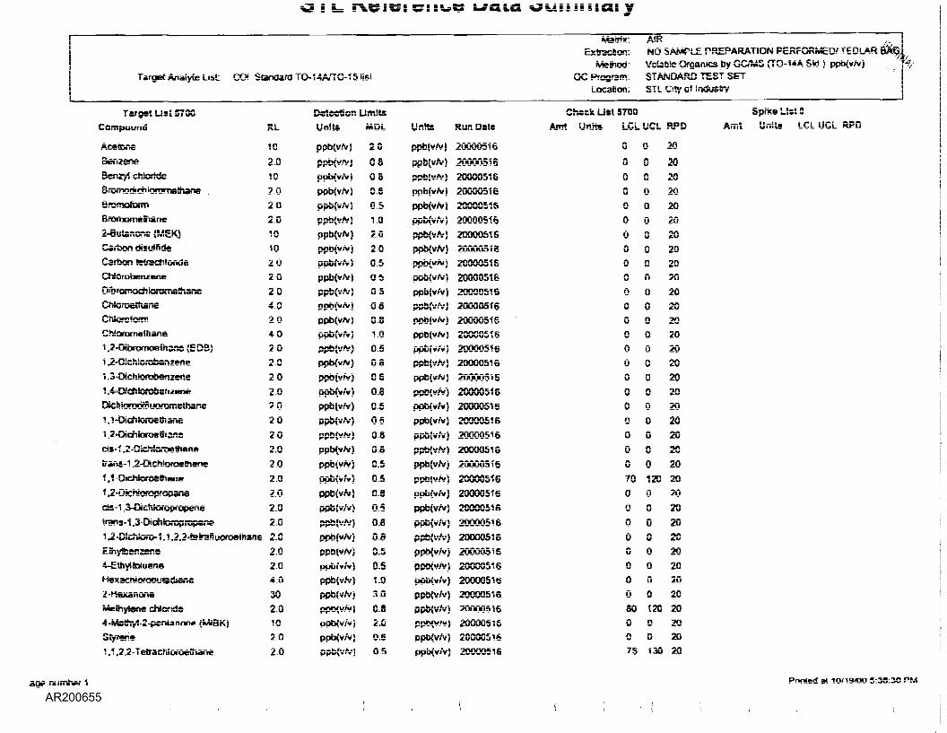
ouiiiincii y
Targse Anaiyu: List OO. Standard TC-14A/TQ-15 list
Tar sst Usl «7QOCompound
A.C€toTi€
BenzeneBsnzyi chlorideBnxnodiehloranielhaneBremotom)Bremoim&mne2-euUnone (MEK?Carbon cjJsuifiOcCart-on -—fscfiSo-HjeChiOfObenzaRg
D!brQ?«©s?terofttsm3r.eChlc-rc -e-nsneChkmtafni
Chioronisih.anai .a-OibromoeUiane (EDB)1 _2-r;Jchiono6enzene1 .3-OicrUoralMnzene1 ,4-DrtfilCfQbsnzsneOichkiradtlluoiwnethanei , 1 -DichlorDeitiane1 ,2>Oi€n;Of3€a!ans
ClS-f ,2-DichloreeVl*n0
lrans-1 ,2-Dic.h.iQfos-:hsnsf.i Dfc~cros~is.".
1 ,2-DictiloropropaneCiS-1 ,3-LHch.iOfOpfOpeo.e
trans-1 ,3-OchkXT?r:,T!psflp
1 J-DichlOfO-1 .1 .2.2-t=?=nvK>-c-e:h5-.sEr.y™fi2sf:=vEihyibiysReH=s~crJc--aousd!6r,8S-HessnOfisMsqr.Tsr.;- chiortds
4-MaBM-2-penURcne (MISK)Sryrene1 ,1 .2.2-Telrachloroe(han«
Datecticn UmlURL
10
2.0102.0202.01010202Q204020402020202.02020202.02.02.02,02.02.G2.02.02.G4.0302.010202.0
UnlU
ppbCv/vi
ppb(y/v)ppbCvre)ppb(¥/V!
ppscvAr)ppb(vAf)ppbivre)
PPb(v~ipj*CvA?)ppb(v/V;
ppbCv/vippo(v/v)ppbcvNjppb(v/V)ppbiv/v)
ppbsv/v)ppb(v?»)DS&CV/V)
ppbiv™}
ppO<Vf«)
ppb(v~yppbsvre)
PP5(V?V)
ppb(v?v}ppb(v™}ppbCwv)ppb(v~}Pvb{v/vSPPbCv/v)ppbiv/v)ppbiv/v)
PPb:y/vSppbcv/y)QPb(V/v)
ppixv/v)
ppfa/VJVi
MDL
20
OSQSOS0.51.0202.00.5QSOSOS0.8VOQ5OS060.6050508OS0.505OS0.508OS0.50.51.03,0O.S2.0G.60.5
Units
ppb{¥/V}
PpblV/V i
ppb(y~5ppbfvre)
ppb(v?v}ppb(y/y}PPbfrMPPbivJvSppb(V~}
ppbivAf}pebivJv)PPb(s#vSppb(v/v)ppb(v/y}ppb(vrv)ppb{V/V)
ppb(vfe)ppb(yAr)ppb(v?v}PPbCvJv)PPb{y?v}ppb(y?y?ppb(y/y)
ppb(v/y}ppb(VJvS
PPbSv/v)ppb(y/y)ppb(v/v)PPb(wv)PptHv/y}ppo(¥/y}PPbCv/v}PPbiv/v}ppb(y/y}ppb(y/y)ppbivAv)
Msnis:Ex sacs en.:
Metma:QC Program-.
LocaSon:
Chsck Us? 5TGO
A«NO SAMPLE PREPARATiON PERFORMED/ TEDLAR W8,vnlab-e OfgaaiCS by (TO-14A Std } ppb(v/v)STANDARD TEST SETSTL Csry of Industry
Ran Dais A»n Un« LCL UCL
200005162000051620000516200005162000051620000516ZGGOGSiS2000051620000516200005162QGCG5152000051S2000051620000516200005162GGOG5152000051 6
200005162DG005162000051620000516200005162000051S200005162GOOG5162000051 S20QQ0516200005162000051620000516200G0516200005162000051620000516200005162GC-XS16
0
000G0000000G000G000000700000000030G075
0
000G00GG000G0000000G0012000000G00'.20GG130
Spiks List 0HPD Astit Units LCL UCL R?u
20
2G20202G2020202G2020202G202020202G20202020202020202020202G2020202G2G20
age r-urnber 1 Fnn-ed e-
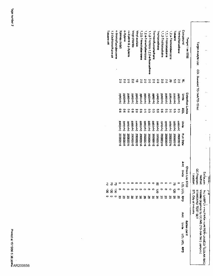
IN) M IO JO -* I\J IO Kl M M IO fu fo l.ri |M ;||o 6 b fa ° a o o o <:> is> b ° i:s b r-
l[l *C3I '131 l:i 1C) 'HI Tl 1C) TOi 'O 1C) "C3 'Kl Tl ir"IEI • • i: in • ' '«; : • •!: S • • ' i: •!'CT Br iir IS i!r r gp ( j- Mr & a c)r Br !:r s .< '«' '« '? '•? «' . c "e '.:' 'I ' '? '«' '« '< '<• 9:<• ::;• ? :? ;? :;r ? :? * ? :;r :;;• ;? ? sr. . . . .
...o o o o ro p o o p ::> o o u t:> o % j.)03 en en c» o on «.n u> </i >:r> en <jn o DI (jm ]••! ::>
'S3' ''«' v ^H "S3' »L V K *!B' !•£ ^5? ' "' ^ ^*! ' ' 'SfOr (jr1 ijj1 icj' w (.r cr op tSr ("r w" & cr cS* (3^ ™>'I? '"? '<:" '<:' '<' '«" '«' '«' "F '"«' '«' V '<:' '<:' "? B".:!) .2 3' i: .:£ .5 5 ;:•: ,:£ i£ £ .:? :?: .:L .£ro M i;i i;,i Ki si i;J i;ti M 10 ly ro 10 ly N) ;ij
u> 'U^ (j^i ifri ILH i3t (jn> cr> lit tji' Cn (]i Oni 11/1 lit il[Ol 'CD (]1i (3D) I'D {Jt Ol1 Oil ICT) C3) 1311 <C11 OHi I3r> O) 'I'
-4 -.1O O
-.1 cjO
... o
£ Io o o o o o o co o o o -J o r- -'! -jo o Q ic:t,.- o
o o o o o o o o -• o o o ••» o c ,,,IJJI W Q tO..1 I - j...
!!•' W 'i? V 'V *•' ISJ| ''•' IM "J '"i" 's( ;»!O O O O O O (13 O O O O O «n rir
1:31 a
T)
!!i'..j>o
'-"N>
toc 1>g jrsir "'
o
'iso
iil'!«['e
9cifi
8
i Ien <:;
fio ||irn oc« M"' 5ffi o
9.Jb
I,V)
C- 0
>
I5rr!|3
;i]5-o
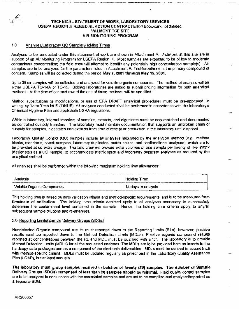
TECHNICAL STATEMENT OF WORK, LABORATORY SERVICESUSE- PA REGION III REMEDIAL ACTION CONTRACTErrori Bookmark: not defined.
VALMONT TCE SITEAIR MONITORING PROGRAM
Sai
Analyses to be conducted under this statement of work are shown in Attachment A. Activities at this site are insupport of an Air Monitoring Program for USEPA Region 111. Most samples are expected to be of low to moderatecontaminant concentration; the field crew will attempt to identify any potentially high concentration sarnpte(s), Airsamples are to be analyzed for the parameters) listed in Attachment A. Trichloroethene is the primary compound ofconcern. Samples will be collected during the period May 7, 2001 through May 115,, 2001.
Up to 35 air samples will be collected and analyzed for volatile organic compounds, The method of analysis will beeither USEPA TO-14A or T'O-15. Bidding laboratories are asked to submit pricing information for both analyticalmethods. At the time of contract award the one of those methods will be specified.
Method substitutions or modifications, or use of I:! IP, A, DRAFF analytical procedures must be pre-approved, inwriting, by Telia Tech NUS (TtNLIS). All analyses conducted shall be performed in accordance with the laboratory'sChemical Hygiene Plan and applicable OSHIA regulations.
Within a laboratory, internal transfers of samples, extracts, and digestates must be accomplished and documentedas controlled custody transfers. The laboratory must maintain documentation that supports an unbroken chain ofcustody lor samples, digestates and extract;; from time of receipt or production in the laboratory until disposal.
Laboratory Quality Control (QC) samples include all analyses stipulated by the analytical method (e.g., methodblanks, standards, check samples, laboratory duplicates, matrix spikes, and confirmational analyses), which are! tobe provided at no extra charge. The field crew will provide extra volumes of one sample per twenty of like matrix(designated as 3 QC sample) to accommodate matrix spike and laboratory duplicate analyses as required by theanalytical method.
All analyses shall be performed within the following maximum holding time allowances:
Analysis
Volatile Organic Compounds
Holding Time
14 days to analysis
This holding time is based on data validation criteria and method-specific requirements, and is to be measured fromtime/date! of collection!. The holding time criteria depicted apply to all analyses necessary to successfullydetermine the contaminant level contained in the sample. Hence, the holding time criteria apply to any/allsubsequent sample dilutions and re-analyses.
2-0 !:!;l!:!!2!;!i!!!
Nondetected Organic compound results must reported down to the Reporting Limits (RLs); however, positiveresults must be reported down to the Method Detection Limits (MDLs). Positive organic compound resultsreported at concentrations between the RL and MIDI, must be qualified with a "J". The laboratory is to provideMethod Detection Limits (MDLs) for all the requested analyses. The MDLs are to be provided both as inserts ID tieharclcopy data packages and as a component of the electronic deliverable:-;. MDLs must be derived in accordancewith method-specific criteria. MDLs must be updated regularly as prescribed in the Laboratory Quality AssurancePlan (LOAF), but at: least annually.
Hie laboratory must group samples* received in Ibatehea; of twenty (21)) samples,, The number of Sample)Delivery Groups (SDGs) comprised of Hess ttiaini 20 samples: should be minimal. Field quality control samplesare to be analysed in conjunction with the associated samples and are not to be cornpilled and analyzed/reported asa separate 8IDG,
\TECHNICAL STATEMENT OF 'WORK, LABORATORY SERVICESUSE-PA REGION 111 RACVALMONT TCE SITEAIR MONITORING PROGRAMPAGE - 2
3.0
Hardcopy deliverable!-; for the requested analyses must be presented in a CLP-Like Deliverable. All data packages;must contain all the elements of a CLP data package including all raw data and summary forms. The data summaryform requirements are detailed in .Attachment B.
All hardcopy data package submissions shall! contain a laboratory case narrative detailing the methodologies andanalyses conducted, and any problems or non-compliances that occurred. The case narrative must also includethe Site Name and 1th® IP reject N/lanacier'isi name. MIDI. information must be provided as an attachment: to thecase narrative (and electronically, as depicted in Attachment C). Data from all analytical runs (i.e., original, dilution,re-analysis) must be reported. All soil matrix sample results shall be reported on an adjusted dry-weight basis.
Electronic deliverable requirements are detailed in Attachment C. The laboratory is to provide 3.5" high-densitydiskette(s) or Compact disk (CD) containing separate database files (DBF) for each analytical fraction (by matrix) inthe formal: identified in Attachment C, This electronic format includes all client sample identifications, sampledilutions, sample reanalysis, and laboratory identifications, as well as other criteria as shown. Toe order ofparameters and values reported oiri the diskette must agree exactly with the final values and parameteroirdeir reported on the date package sample result suirnrmiirfei,. Any corrections made to the hardcopy datamust also be made to the electronic file. Appropriate gualifjers as identified by the analytical protocol must also beincluded; la^ojatoj ^CjTpji:conjiglja^cjB_^pdes are NOT to "be depicted. Each diskette is to be properly labeledwith the laboratory name, project name, file name(s), fraction identifiers, and laboratory electronic deliverablescontact person, All! diskettes must be provided! vims free.
As part of the laboratory case narrative, it: is required that the Laboratory Quality Assurance Manager sign anattestation statement verifying that all electronic diskette deliverables exactly match the data summary forms (i.e.,Form Is).
Samples submitted for chemical analysis shall be shipped to the laboratory within 24 hours of collection (wheresample pick-up by the laboratory is not applicable). Please indicate (on Attachment A), whether or not samplepick-up (itiindl bottleware drop-off) at the site is available at no extra charge. Saturday -receipt sampleshipments may also be requested with a minirnuirn of two days advance notice.
The Project Manager for this project is Mr. INIeil Teamerson and he must be contacted in the event of any laboratoryproblems that could impact project deadlines (i.e., late deliverables, technical problems in the lab that could lead tolate deliverables.) To insure good communication it is required that the laboratory's appointed project managercontact Mr. Teamerson once a week. Ill: is also a requirement that the laboratory project manager fax copies of thechain of custody forms and completed sample receipt: forms as they are received by the laboratory to the TtlNLISProject: Manager.
Contact information for Mr. Teamerson follows:
Tetra Tech IMUS600 Clark Avenue, Suite 3King of Prussia, PA 19406-1433Phone: (310-491-9688Fax: 610-491-9645e-mail: [email protected]
tilNilCAL STATEMENT OF WORK, LABORATORY SERVICESUSEPA REGION 111 IRACVALMONTTCESITEAIR MONITORING PROGRAMPAGE-4
Contract concerns, and response Ito this solicitation, are to ICXES directed to::
Mi>.. Margaret PriceSubcontracting OfficerTetra Tech IMUIS600 Clark Avenue, Suite 3King of Prussia, PA 19406-1433Phone: 610-491-9688Fax: 610-4914)645e-mail: p_rjcemj ttnus.com
Please confirm available capacity', and complete the costing information indicated in .Attachment A., limit cost foranalysis is Ito iiniclydle coi'iiipeniHiaitioiri loir all !EiiEMrviic«iJ5> diE!Scirilbied hereiitii, iiiicliLidiinig provislioin of toottleware,preserve lives, coolers;,, labaraitoiiy qualily control anialysesi;, iBitoirage, iEiirid
ATTACHMENT ANUMBER OF SAMPLES/ANALYTICAL METHODS
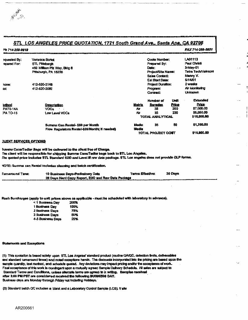
horn:UK:
PATO-14AFA TO- 18
^^^^
Varontan litaHbl:S'l'l. PIIM:nw[f[i4!iO Wlltan Pill'«ny,Pttabuigh. I='A IISiiEiUI
<li;!.a;!l>-:Z14l!
Qyolm Niiiirrtimr:PiwpairiMJI By:Mil:IF'nqjncMSMliD MairmiK
Piull ChiMIa-Ti
Probe* rjuirnteMr
IILlKblMlillilillUliilt
VOOi •LowLeMlVOCt
Sitinruiniii Cm IFlinKtiil-i|l!>» |!.»r INtoiiltol:kmi> RoflruinhEinn |lt«iirilsnl4:uiMiMrililii| II MwiliMqi
MlrAir
X3!S i!3»
ISO
kinnirntii 'Dmnn'iwdlbnr IEI«i(|fl> wllll bun dnWtrnriKdl to Urim dlMnnll ln»« «il' Omirpi.nm dlhml: will ltm> innm|M)rallPil«> tor i>hl|!>j;>lir>|] tanninini Ciiiriii/TiKJlliiir IxnuMi toch; to till. UHI ta|)Nllmii,.rihn qiMiMI ipirlon iKhyuta iEITI. Staridnnl IIECI0 IILIUE! tira l 111 imw dMii |p«i<Etai|(|a>., till. lUm mnpilta I»OM nnolt ipmMo O.P tariinn.
MOTI-;: Suimnai am RiHilcnl lliridhMhim dliHiinliiffl miwEl l:>nl>c:li «HiiltHWiiiililinra.
l'u«riiiiuiE)uii«dl lIllniNi: II innrnm OHIME!|]WII«
Itaidn !l4Liri:liiir[|iin> (inpv% to unriM iprtaimi iitoawn inn< 11 lEIwilnwnn Dny 20M1 BiiiilnwHiii Onrc IIMM2 l:iiiiili>nnti i:)ur,ni3 lEIuntaini Oiitirn
• uriuiirl IENI n»i; i'111111 Intartitarir Ihri
Mil Bi
I'll Thin <|LH)tiirilm in IraiiiMid itoWy lupcm OTL. I.M M&i>\iaf nbindiincl |pra<ta:l (raullrHn QMX, inimcl iitaMrKlml llmnnrauml llmm) nund IKIIIMJI iintcn^Uoiw liiiiriiln, limn dlnopiLinto IrMiipiPpmliimll Inllci Hun ||Hli:iniEl mm bmnnd u(F»(ini tlwi)iimmpli) iciuimrilllv, tniitt iriuitiiMdl, mriijl iidhndiilln mnioliiKl. toy da^Wlomi irnny Unpaid |MWIri||i mriiMir tni imiipiniriiiin inl'miiiiltFlruil i9ia»i|piiliimon c« thin wvnli: in ocwrtlnw nut (uipaini n loriulwilly iifliPirad l nmipilkn Dotrawy Sd wlullin. Mil iiiilna nirw itiibjMKJl lla
Camllllainn, umliHiiii! iilliunruilUi Imriw imii iiiiriuiiJI to Im wiling. Illmnnigta inimuilwiMlifflMM !I:WI PIMI NT lira ciMiiiiil<»ni»il inmenlwhdl Illwii IMEnMlli»|| MWNIIEIInl IMY,IkraillrHiiU!; (liipi nra Mtemdny tiroutfi Friday ni!<t taluidllrin IMMIiqrn.
(2) Slancliinl talch QC liKAidkim in blarti and n LntainnoiY Onnlrai SIHII NI (l.C:!ii). If itlln
ATTACHMENTBHARDCOPY DATA SUMMARY FORM REPORTING REQUIREMENTS
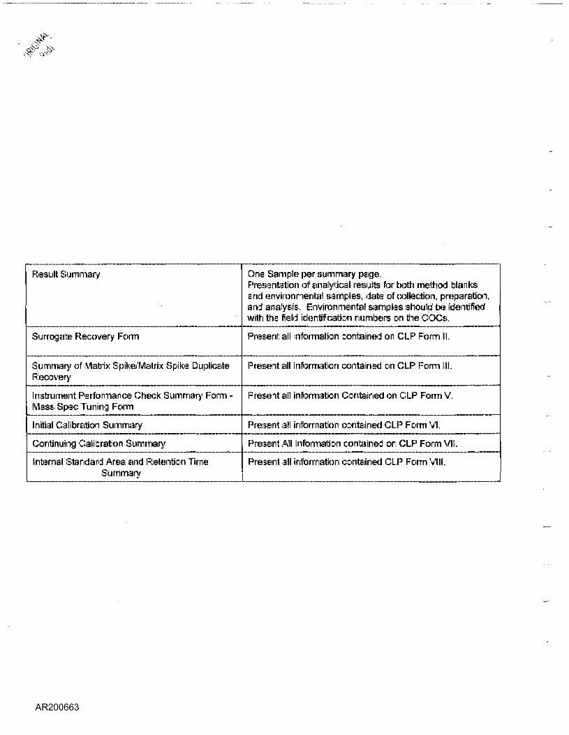
Result Summary
Surrogate Recovery Form
Summary of Matrix Spike/Matrix Spike Duplicate!Recovery
Instrument Performance Check Summary Form -Mass Spec Tuning Form
Initial Calibration Summary
Continuing Calibration Summary
Internal Standard Area and Retention TimeSummary
One Sample per summary page.Presentation of analytic-ill results for bolt) method blanksand environmental samples, date of collection, preparation,and analysis. Environmental samples should be identifiedwith the field identification numbers on the COCs.
Present all information contained on CLP Form III.
Present all information contained on CLP Form III.
Present all information Contained on CLP Form V.
Present all information contained CLP Form VI.
Present All Information oontained on CLP Form VII.
Present all information oontained CLP Form VIII.
ATTACHMENT CELECTRONIC DELIVERABLE REQUIREMENTS
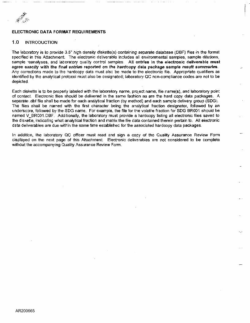
ELECTRONIC DATA FORMAT REQUIREMENTS
'1,0 INTRODUCTION
The laboratory is to provide 3.5" high density diskette(s) containing separate database (DBF) files in the formal:specified in this Attachment. The electronic deliverable includes all environmental samples, sample dilutions,sample reanalyses, and laboratory quality control samples All! entries in the electronic deliverable nniiin'l:agree exactly with ithe final entries reported on the hardcopy data package sample resuIII tiiJinnriiiiries.Any corrections made to the hardcopy data must also be made to the electronic file. Appropriate qualifier!* asidentified by the analytical protocol must: also be designated; laboratory QC non-compliance codes are not: to bedepicted.
Each diskette is to be properly labeled with the laboratory narnie, project name, file name(s), and laboratory pointof contact, Electronic 'files should be delivered! in the same fashion as are the hard copy data packages. Aseparate .dbf file shall be made for each analytical fraction (by method) and each sample delivery group (SDG).The files shall be named with the first character being the analytical fraction designator, followed by anunderscore, followed by the SDG name, For example, the file for the volatile fraction for SDG BR001 should benamed V_BR001.DBF. Additionally, the laboratory must provide a hardcopy listing all electronic files saved tothe diskette, indicating what analytical fraction and matrix the file data contained therein pertain to. All electronicdata deliverables are due within the same time established for the associated hardcopy data packages.
In addition, the laboratory QC officer must read and sign a copy of the Quality Assurance Review Forniidisplayed on the next page of this Attachment. Electronic deliverables are not: considered to be completewithout the accompanying Quality Assurance Review Form.
I __________________, as the designated Quality Assurance Officer, hereby attest that iEillelectronic deliverable^ have been thoroughly reviewed and are in agreement with the associated hardcopy data.The enclosed eledtronic files have been reviewed for accuracy (including significant figures), completeness and
format. The laboratory will be responsible for any labor time necessary to correct enclosed electronicdeliverable!-; that: have been found to be in error. I can be reached at:|__J________ if there are any questions or problerns with the enclosed electronic deliverables.
Signature:_______________ Title:_______________ Date:
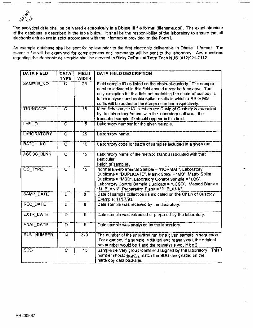
The analytical data shall be delivered! electronically in a Dbase III file format (filename.dbf"). The exact structureof the database is described in the table below. It shall be the responsibility of the laboratory to ensure that allelectronic entries are in strict accordance with the information provided on the Form I.
An example database shall! be sent for review prior, to the first electronic deliverable in Dbase 111 format Theexample file will be examined for completeness and comments will be sent to the laboratory. Any questionsregarding the electronic deliverable shall! be directed to Ricky DePaul at Tetra Tech NLIS (412)921-7112.
DATA FIELD
SAMPLE_NO
TRUNCATE
LAIB.JD
LABORATORY
BATCH..NO
AS8OC...BI..NK
QC.TYPE
8AMPJDATE
REC...DATE
EXTR_DATE
ANALJDATE
RUNJMUMBER
SDG
DATATYPE
C
c
C
ccc
c
ID
ID
D
D
N
C
FIELDWIDTH
25
15
15
25
10
15
15
8
8
8
8
2 (0)
15
DATA FIELD DESCRIPTION
Field sample ID as listed on the chain-of-custody. The samplenumber indicated in this field should never be truncated. Theonly exception for this 'field not matching the chain-of-custody isfor reanalyses and matrix spike results in which a RE: or MSsuffix will be addled to the sample number respectively.if the field sample ID listed on the Chain elf Custody is truncatedby the laboratory for use with the laboratory software, thetruncated sample ID should appear in this field.Laboratory number for the given sample.
Laboratory name.
Laboratory code for batch of samples included in a given run.
Laboratory name of the method blank associated with that:particularbatch of samples.Normal Environmental Sample ::: "NORMAL", LaboratoryDuplicate == "DUPLICATE;11, Matrix Spike = "MS", Matrix SpikeDuplicate == "MSD", Laboratory Control Sample ::: "LCS",Laboratory Control Sample Duplicate == "ILCSD", Method Blank ="M BLANK", Preparation Blank = "P BLANK".Date of sample collection as indicated on the Chain of Custody.Example: 1 1/07/93.Date sample was received by the laboratory.
Date sample was extracted or prepared by the laboratory.
Date sample was analyzed by the laboratory.
The number of the analytical run for a given sample in sequence.For example, if a sample is diluted and reanalyzed, the originalrun number would be 1 and the reanalysis would be 2.Sample delivery group identifier assigned by the laboratory. Thisnumber should exactly; match the SDG designated on thehardcopy data package.
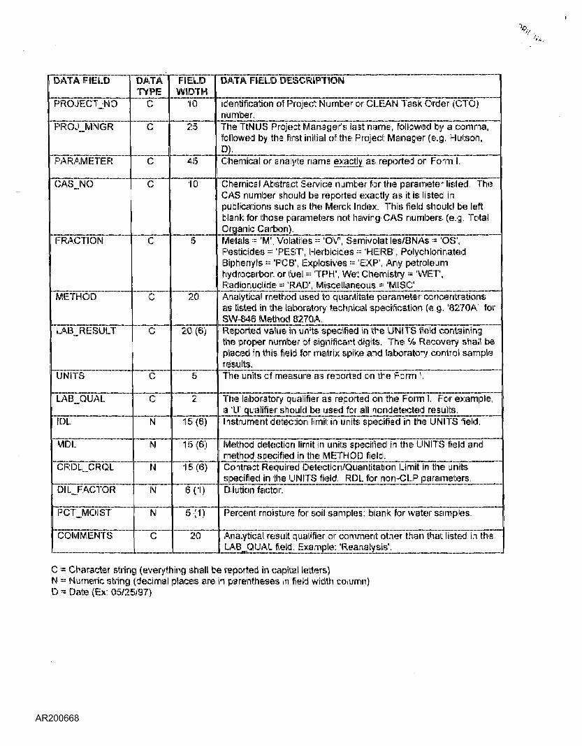
DATA FIELD
PROJECTING
PROJ_MNGR
PARAMETER
CAS..NO
FRACTION
METHOD
LAB.JRIESULT
UNITS
LAB_QUAL
IDL
IMIDL.
CRDL_CRQL
DIL_FACTOR
PCTJ/IOIST
COMMENTS
DATATYPE
C
c
C
c
c
c
c
c
cM
IM
IM
M
N
C
FIELDWIDTH
10
25
45
10
5
20
20 (6)
5
2
15(6)
15(6)
15(6)
6(1)
5(1)
20
DATA FIELD DESCRIPTION
Identification of Project Number or CLEAN Task Order (CTO)number.The TtlMLIS Project Manager's last name, followed by a comma,followed by the first initial of the Project Manager (e.g. Hutson,D)-Chemical oranalyte name exactly as reported on Form I.
Chemical Abstract Service number for the parameter listed. TheCAS number should be reported exactly as it is listed inpublications such as the Merck Index. This field should be leftblank for those parameters not having' CAS numbers (e.g. TotalOrganic Carbon).Metals •= 'M1, Volatiles = 'OV, Semivolatiles/BNAs = 'OS",Pesticides =: 'PEST, Herbicides = 'HERB", PolychlorinatedBiphenyls :::: 'PCS', Explosives =: 'EX.P', Any petroleumhydrocarbon or fuel = TPH", Wet Chemistry = 'WET,Radionuclide := "RAD", Miscellaneous =: 'MISC'Analytical method used to quantitate parameter concentrationsas listed in the laboratory technical specification (e.g. '8270A' forSW-846 Method 8270A.Reported value in units specified in the UNITS field containingthe proper number of significant digits. The % Recovery shall beplaced in this field for matrix spike and laboratory control sampleresults.The units of measure as reported on the Form 1.
The laboratory qualifier as reported on the Form 1. For example,a 'U' qualifier should be used for all nondetected results.Instrument detection limit in units specified in the UNITS field.
Method detection limit in units specified in the UNITS field andmethod specified in the METHOD field.Contract Required Detection/Quantitation Limit in the unitsspecified in the UNIT'S field. RDL for non-CLP parameters.Dilution factor.
Percent moisture for soil samples; blank for water samples..
Analytical result qualifier or comment other than that listed in theLAB_ QUAIL field, Example: 'Reanalysis'.
C ;= Character string (everything shall be reported in capital letters)N ::: Numeric string (decimal places are in parentheses in field width column)D = Date (Ex: 05/25/97)

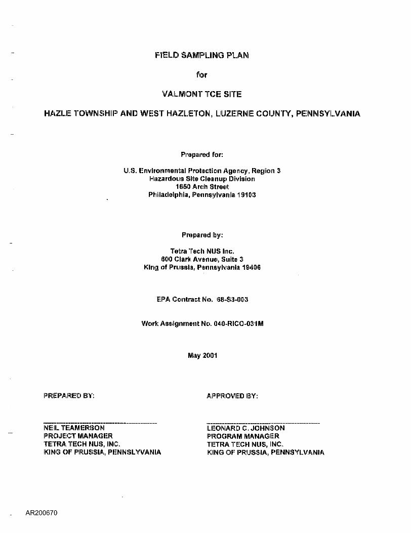
FIELD SAMPUNG PLAN
for
VALMONT TCE SITE
HAZLE TOWNSHIP AND WEST HAZLETON, LUZERNE COUNTY, PENNSYLVANIA
Prepared for:
U.S., Environmental Protection Agency, Region 3Hazardous Silts ClleainiiJip Division
11(8180 Arch StreetPhiladelphia, Pennsylvania 191 (Kl-
Prepaired by:
Tetra Tech NUS line,(EiCICI Cllarh: Aveniuie, Smite 3
King of Pmssiiii,, IPuininisylvaniii 191406
EPA Conttraict No. 68-S3-OIO!)
Work Alignment No. 040I-RIICO-031M
May 2001
PREPARED BY: APPROVED BY:
NEIL TEAMERSONPROJECT MANAGERTETRA TECHI NUS, INC.KING OF PRUSSIA, PENNSLYVANIA
LEONARD C, JOHNSONPROGRAM MANAGERTETRA TECH NUS, INC.,KIING OF PRUSSIA, PENNSYLVANIA
"ItTETRA TECH NUS, INC., %.,..........................................................————————————————— -''/I'd,600 Clark Avenue. Suite 3 • King of Prussia, PA. 19406-1433 ,\, '(610) 491-9688 •• FAX (610) 491 -9645 « www.tetratech.com
PHIL-15235
Project Number 2107
May 16, 2001
Mr. Romuald Roman (3HS22)United States Environmental Protection Agency (ERA)1650 Arch Street:Philadelphia, Pennsylvania 19103-2029
Reference: Response Action Contract - EPA Region 3 (RAG 3)EPA Contract Number 68-S6-3003
Subject: Field Sampling Plan and Health and Safely PlanValmontTCESiteRemedial Investigation/Feasibility Study (RI/FS)EPA Work Assignment No. 040-RICO-031M
Dear Mr. Roman:
Einclosed please find the field sampling and health and safety plans for groundwater and air sampling andanalysis at the subject site. These documents address field activities to be performed during May 2001only.
Please contact me if you have any questions or comments.
Sincerely,
Neil TeamersonProject Manager
ANT/vh
Enclosures
c: Elaine Spiewak (EPA Region III) (without enclosures)Leonard Johnson (Tetra Tech NUS) (without enclosures)
TABLE OF CONTENTS
Section Page
1.0 BACKGROUND......................................................................................-..................-......................!1.1 INTRODUCTION.................................................................................................................11.2 LOCATION ..........................................................................................................................11.3 SITE DESCRIPTION ...........................................................................................................11.4 BACKGROUND.....................................................................................-............................^
2.0 PROJECT DESCRIPTION ...............................................................................................................42.1 OBJECTIVE......................................................................................................................-.^2.2 SCOPE OF WORK..............................................................................................................5
3.0 SAMPLING PROCEDURE ...............................................................................................................53.1 RESIDENTIAL WELL SAMPLING,........................................................................................,..,53.2 EQUIPMENT DECONTAMINATION ...................................................................................5
4.0 ANALYTICAL PARAMETER.........................................................................................................5
5.0 QUALITY ASSURANCE AIMD QUALITY CONTROL.......................................................................65.1 RESPONSIBILITY...............................................................-..............................................^5.2 FIELD QC ...........................................................................................................................65.3 LABORATORY QC..............................................................................................................75.4 DATA VALIDATION.............................................................................................................7
6.0 DELIVERABLES.............................................................:.................................................................7
7.0 REFERENCES......................................^
FIGURES
figure Page
1 SITE LOCATION MAP......................................................................................................................22 SAMPLING LOCATION MAP...........................................................................................................3