Embed Size (px)
Citation preview
The 11th International Fluid Power Conference, 11. IFK, March 19-21, 2018, Aachen, Germany
The DOT concept is a result of research projects at the Technical University Delft, which included indoor tests at Technical University Delft and IFAS/RWTH Aachen.
Figure 1: The DOT concept: a seawater hydraulic network where every wind turbine rotor is directly coupled to
a positive displacement pump and electricity generation is centralized
1.2 The necessary first step of development
So far, all experiments had been done in a controlled indoor environment. Hence the first challenge after founding the company was to build and test a hydraulic drive train outdoors, in a real world and full-scale wind turbine.
In a collaboration between DOT and the TU Delft, a project was set-up in 2015 to retrofit a second-hand 600kW Vestas V44 onshore turbine into a full-scale DOT hydraulic wind turbine.
Figure 2: Wind power flow schematic
Figure 2 shows the typical power flow from wind to electricity. The wind turbine rotor converts wind power to mechanical power in the form of (high) torque and (low) rotation speed. A major challenge for the development of DOT is the commercial unavailability of low-speed, high-torque water pumps to connect directly to the rotor. However, for oil hydraulics such machines are available, which resulted in the idea to add an oil circuit which acts as a hydraulic gearbox, as schematically represented in Figure 3. This idea was already presented at the IFK 2014 in Aachen along with the simulated power performance /6/ of a 500kW DOT. Hence, to speed up development and showcase the practical feasibility of the hydraulic drive train, this intermediate concept was implemented using off-the-shelf components. Based on previous research, the design for a 500kW hydraulic drive train was made to fit the wind turbine. The reconfigured turbine was dubbed the DOT500. The hydraulic drive train was modelled theoretically and numerically prior to executing an extensive in-field test plan; using this set-up, two alternative torque control strategies were evaluated, and rotor and generator power optimizations were performed.
The 11th International Fluid Power Conference, 11. IFK, March 19-21, 2018, Aachen, Germany
Field tests of the DOT500 prototype hydraulic wind turbine
Dr.ir. Niels Diepeveen*, ir. Sebastiaan Mulders**, dr.ir. Jan van der Tempel*
DOT BV, Raam 180, 2611WP, Delft, The Netherlands* Faculty of Mechanical Engineering, Delft University of Technology,
Mekelweg 2, 2628 CD Delft, The Netherlands** E-Mail: [email protected]
To reduce turbine mass, maintenance requirements, complexity, and thus the Levelized Cost of Energy (LCOE) for offshore wind, the Delft Offshore Turbine (DOT) concept combines individual hydraulic drive train wind turbines with a centralized generator system. In 2015 DOT built and tested a large-scale prototype, by retrofitting a 600kW wind turbine with a hydraulic drive train using commercial off-the-shelf components. The goal was to showcase a proof of concept from a technological and controllability point-of-view. This paper presents the results of building and testing the DOT500. Its drive train has an oil-hydraulic stage and a water-hydraulic stage. The method of rotor torque control with spear valves is novel and proves to be a substitute for conventional implementations.
Keywords: offshore wind, fluid power transmission, water hydraulics Target audience: offshore wind industry, water hydraulic component suppliers
1 Introduction
1.1 Background DOT hydraulic wind turbine concept
The drive train of horizontal-axis wind turbines (HAWTs) generally consists of a rotor-gearbox-generator configuration in the nacelle, which enables each wind turbine to produce and deliver electrical energy independent of other wind turbines. While the HAWT is a proven concept, the turbine rotational speed decreases asymptotically and torque increases exponentially with increasing blade length and power ratings. The increased loads primarily affect the gearbox-generator combination, which makes it a maintenance critical and high mass component in the turbine /1/. The complete wind turbine support structure is designed to carry this mass, which in turn leads to extra material, mass and thus cost of the wind turbine /2/. Offshore wind turbines are getting ever larger, resulting in lower rotation speed and higher torque at the rotor axis. With that, the case for compact hydraulic power trains is becoming ever stronger.
In an effort to reduce turbine mass, maintenance requirements, complexity, and thus the Levelized Cost of Energy (LCOE) for offshore wind, hydraulic drive train concepts have been considered in the past /3/. However, so far none have been commercially realised.
The DOT concept consists of a seawater hydraulic network where every wind turbine rotor is directly coupled to a positive displacement pump and electricity generation is centralized, creating an offshore hydro-powerplant, as schematically represented in Figure 1. This system also enables multiple wind turbines to be controlled collectively which distinguishes it from earlier proposed hydraulic drive trains. The main benefits of this drive train system with respect to the current state-of-the-art are:
• High torque to mass ratio, i.e. mass reduction of the wind turbine nacelle by more than 50% /4/
• Simplification of offshore wind power electronics, a significant contribution to turbine downtime /5/
531
GR
OU
P I
- 5

The 11th International Fluid Power Conference, 11. IFK, March 19-21, 2018, Aachen, Germany
One of the few manufacturers in the world that supplies pumps with a range of operation covering those of wind turbine rotors is Hägglunds, part of Bosch Rexroth Group. For the DOT500 the CB840 motor was selected to function as pump, directly coupled to the turbine rotor. An overview of the final setup of the DOT500 drive train is shown in Figure 5. Oil hydraulic piping (three hoses with 2-inch inner diameter) was dimensioned for pressure loss of less than 1% and runs roughly 40 meters from the pump in the nacelle via a swivel (for continuous yaw-rotation) to the tower base. Here, a Bosch A6VLM oil motor converts hydraulic power into mechanical power. At this location, the inline filters are placed along with a hydraulic power unit (HPU), which controls the pressure in the oil feed lines (three 3-inch hoses). Filled up, the piping thus contained roughly 1000 liters of inherently biodegradable oil with viscosity 68cSt at 40°C. At normal operating conditions, the oil temperature is around 50°C with viscosity of around 43cSt.
The oil motor is coupled to a KAMAT 80120G water pump. Two 3-inch hoses direct the high-pressure water flow away from the wind turbine to the nearby Pelton turbine-generator. At the Pelton turbine, two spear valves control the two nozzle areas and thereby the pressure in the both the water and oil hydraulic circuits, and hence the braking torque experienced by the wind turbine rotor.
Due to the lack of a grid connection, power from the generator was either re-used for boost and control systems, or dissipated into heat by a break-resistor. The water exiting the Pelton turbine is caught in a reservoir. A centrifugal pump sends the water via a filter back to the water pump at the tower base. An overview of the properties of the rotor and the drive train of the DOT500 are given in Table 1.
Turbine properties Oil circuit properties Water circuit properties
Rotor diameter 44m Nominal pressure oil 240bar Nominal pressure water 80bar
Nominal power 600kW Nominal flow rate 1480l/min Nominal flow rate 3482l/min
Nominal speed 28rpm Stroke volume oil pump 52.8l/rev Stroke volume water motor 2.3l/rev
Nominal torque 205kNm Stroke volume oil motor 1.0l/rev Pelton wheel pitch diameter 0.77m
Table 1: DOT500 rotor and drive train properties.
At nominal conditions for the DOT500 set-up, the water circuit experiences a flow of approximately 3500l/min. A significant design constraint is the required minimum flow for efficient performance of the Pelton turbine. This effectively limits the design pressure for the water hydraulic circuit at 80bar. If the flow is insufficient, the water jet (partly) disperses into mist before it hits the buckets on the Pelton wheel, thus reducing the efficiency of the energy conversion process /7/. Thus, if more flow were available, the design pressure could be increased, whilst maintaining maximum Pelton turbine efficiency.
Figure 5: DOT500 drive train layout at the test site
The 11th International Fluid Power Conference, 11. IFK, March 19-21, 2018, Aachen, Germany
Figure 3: Simplified hydraulic diagram of the DOT500 prototype wind turbine drive train
After dismantling the V44 wind turbine, components of the original drive train were integrated into the indoor fluid power transmission system test setup, as seen on the left of Figure 4. By back-driving the V44 gearbox, a low-speed high-torque wind turbine rotor was simulated. Using power electronics, electric power feedback was applied to reduce power consumption. The test setup was built-up in three stages. First, the two large electric motors were tested back to back. Second, the wind turbine gearbox and the oil circuit were integrated and tested. Finally, the water circuit was integrated and tested.
After functional, failure and performance tests, the turbine was reconfigured to become the DOT500. In June 2016, the DOT500 was commissioned at the Maasvlakte II near Rotterdam (Figure 4, right).
Figure 4: Left: the DOT500 drive train test setup in the workshop in Delft. Right: the DOT500 prototype after commissioning in the port of Rotterdam.
2 Overview of main drive train components
At rated conditions the wind turbine produces approximately 600kW of mechanical power at the rotor, at rotational speed and torque of 28RPM and 205kNm, respectively.
533
GR
OU
P I
- 5
The 11th International Fluid Power Conference, 11. IFK, March 19-21, 2018, Aachen, Germany
4.2 Controllability
The DOT500 wind turbine operation is controlled in two ways:
1. Aerodynamically, using the blade pitch control system
2. Hydraulically, using the spear valve-nozzle combination at the Pelton turbine
The second is a feature unique to the DOT concept and unprecedented.
Part of the test program was the validation of the hydraulic torque control strategy in real life conditions. Two spear valve torque control strategies were evaluated. The first (A) was based on operating at maximum rotor power, i.e. aerodynamic efficiency, extracting as much power as possible from the wind. The other (B) strategy was based on the idea of passive nozzle control /8/, which was achieved by operating at or near maximum rotor torque. The spear valves are set at a predetermined set position. As a consequence, the available mechanical power from the rotor decreases, but overall system power increased as a result of operating in more favorable efficiency envelopes of the individual system components. The difference in these strategies is manifested below-rated wind speed.
At start-up, the blades are pitched to 45 degrees to gain torque whilst the spear valves are fully opened, minimizing system torque to speed up the rotor. In below-rated operating conditions, the spear valve position is used to control the system torque, (function of pressure determined by spear valve area) as function of the rotor speed. In this control region, the blade pitch is fixed at 0 degrees, the so called fine-pitch angle. In near-rated conditions, the spear valves are actively controlled to regulate the rotor towards rated speed. For above-rated conditions (600kW rotor power), the corresponding spear valve minimum area setting is maintained, fixating the rated system torque. Blade pitch control ensures the rotor speed is regulated to its nominal value of 28 RPM.
The in-field tests proved that in the below-rated region, maximum rotor power control can be achieved, but that operating the rotor at maximum torque with passive nozzle control yielded more power output and thus higher total system efficiency. In above-rated conditions, the control strategy stabilizes the turbine and succeeds in maintaining rated rotor speed and power using active pitch control. More details on the controls of the DOT500 are found in /9/.
A concern raised beforehand was the possible occurrence of stability problems due to the large volume of oil in the piping. However, this was never observed. Two reasons for this are the large mass moment of inertia of the rotor in relation to the fluid inertia in the piping and the damping effect caused by the relatively low efficiency of the oil motor.
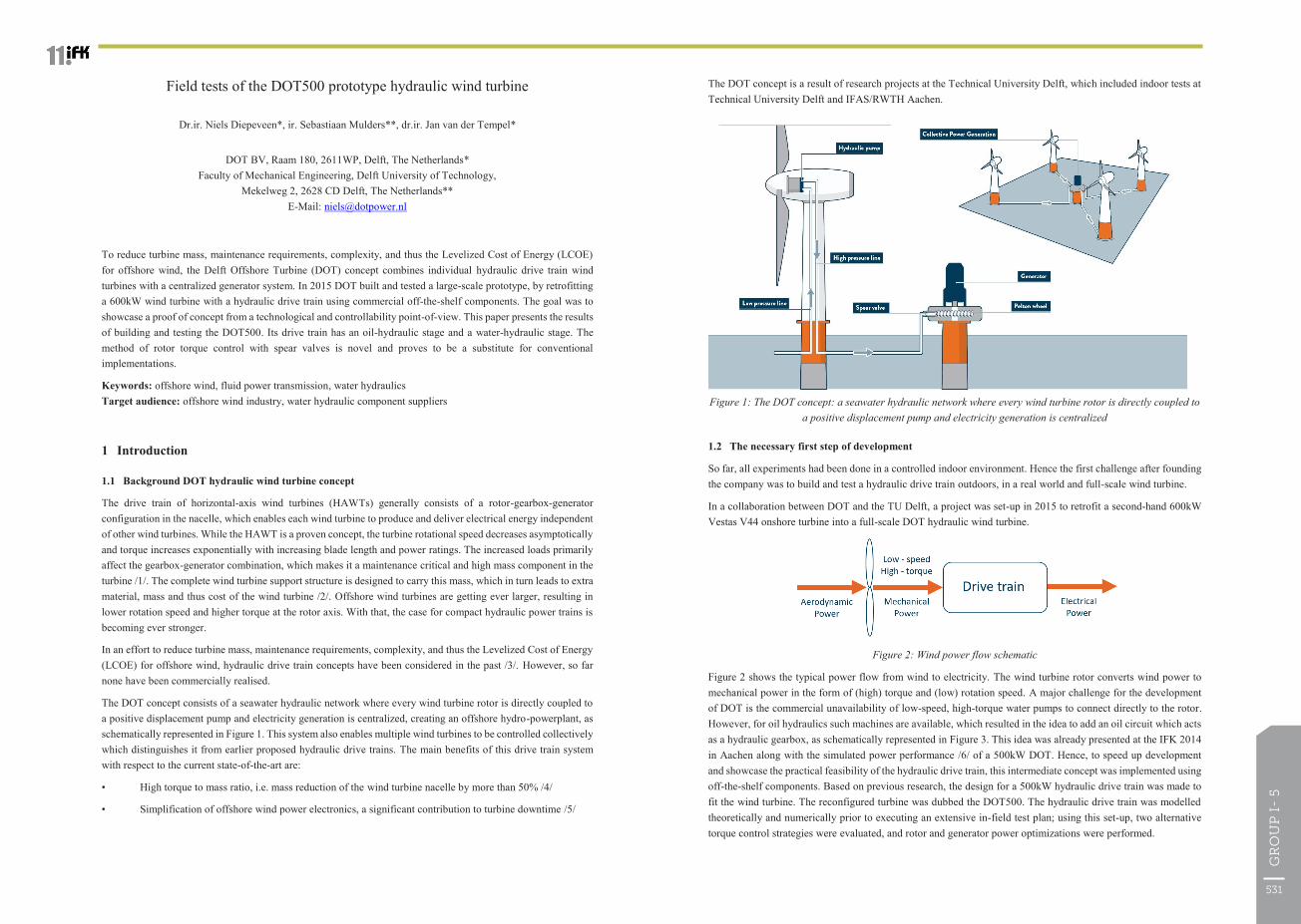
4.3 Power performance
Figure 7: Left: experimentally derived rotor power curve of the DOT500 turbine. The grey dots represent field recorded data, binned per 0.5 m/s wind speed in the blue line. Results are compared to the original Vestas V44 data sheet (red) and theoretical maximum power (green). Right: the power vs pressure and flow in the water
hydraulic circuit.
The 11th International Fluid Power Conference, 11. IFK, March 19-21, 2018, Aachen, Germany
3 Design for safe operation
The most important safety feature in any wind turbine is that one should always be able to stop the rotor. In modern wind turbines, this is done by pitching the blades to the vane position.
An additional method for stopping, enabled by the hydraulic configuration and implemented DOT500 wind turbine, is by increasing the system torque. For the event that pitch actuation would not work, a large cartridge valve was included. By activating this valve, the flow in the high-pressure side of the pump manifold is choked, thereby increasing the pressure and thus system torque, decelerating the rotor. The challenge of implementing this component was to avoid choking the flow too much too fast, which could lead to an extreme pressure surge and high forces on the blade roots due to rapid rotor deceleration.
The emergency stopping procedure was handled via a three-staged approach:
1. Pitch emergency stop: an emergency valve is opened in the pitch hydraulic power unit. The blades are pitched towards feather (90 degrees) at maximum pitch rate.
2. Hydraulic emergency stop : if the rotor does not decelerate sufficiently fast within a predefined time period after initiation of step 1, the hydraulic emergency stop is activated. The high-pressure oil line is chocked, leading to a controlled increase in pressure, which leads to an increased system torque. The system torque is increased up to the point where it exceeds the aerodynamic torque from the rotor, leading to rotor standstill. To avoid excess breaking torque, the choke setpoint is automatically regulated as function of the operating pressure. Hence this method is applicable throughout the operational envelope of the wind turbine.
3. Electronic parking brake: once the rotor is at standstill, this step is initiated. All electronic power to the turbine is cut-off. The last step is never activated when the rotor is still running, as all turbine control is lost when power is lost.
The health of the turbine was continuously monitored via a staged alarm handling protocol. The three main turbine states were: Idle (turbine idling, waiting for input), Standby (turbine ready to operate, all boost systems active) and Power Production (turbine operational, producing electricity). Forward and backward switching between states is done via four transient states, in which the elapsed time is monitored and compared to a threshold value: (1) start-up of oil and water boost systems, (2) rotor start-up sequence, (3) rotor stopping sequence and (4) shutdown of oil and water boost systems.
4 Results
4.1 Nacelle mass reduction
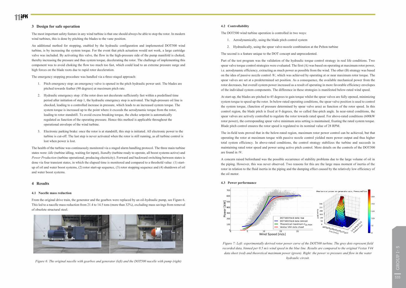
From the original drive train, the generator and the gearbox were replaced by an oil-hydraulic pump, see Figure 6. This led to a nacelle mass reduction from 21.4 to 14.5 tons (more than 32%), excluding mass savings from removal of obsolete structural steel.
Figure 6: The original nacelle with gearbox and generator (left) and the DOT500 nacelle with pump (right)
535
GR
OU
P I
- 5

The 11th International Fluid Power Conference, 11. IFK, March 19-21, 2018, Aachen, Germany
During turbine commissioning, a supervisory control scheme was developed, together with a turbine fault detection system, enabling safe operation of the turbine under all conditions. The developed DOT hydraulic wind turbine control strategies proved to be safe and stable over the full turbine operating range. Active and passive spear valve control are a feasible control substitute for industry standard generator torque control.
The DOT500 drive train was built with an oil pump in the nacelle. The next step for DOT is to develop a low-speed high-torque seawater hydraulic pump, that can be coupled directly to the rotor of a turbine /10/. This will enable the construction of a wind turbine with a single (sea)water hydraulic drive train.
6 Acknowledgements
The research presented in this paper was part of the DOT500 ONT project, which was conducted by DOT in collaboration with the TU Delft and executed with funding received from the Ministerie van Economische zaken via TKI Wind op Zee, Topsector Energie.
References
/1/ A. Ragheb, M. Ragheb, Wind turbine gearbox technologies, in: Nuclear & Renewable Energy Conference (INREC), 2010 1st International, IEEE, 2010, pp. 1-8.
/2/ P.-E. Morthorst, S. Awerbuch, The economics of wind energy, EWEA, 2009.
/3/ E. Innes-Wimsatt, C. Qin, E. Loth, Economic benefits of hydraulic-electric hybrid wind turbines, International Journal of Environmental Studies 71 (6) (2014) 812-827.
/4/ Diepeveen, N.: On fluid power transmission in offshore wind turbines, PhD thesis, Technical University of Delft, August 2013
/5/ Faulstich S., Hahnand B., Tavner P.J.: Wind turbine downtime and its importance for offshore deployment, Journal of Wind Energy, ed.14, p.327–337, 2011
/6/ Diepeveen, N., Jarquin Laguna, A.: Preliminary design of the hydraulic drive train for a 500kw prototype offshore wind turbine. Proceedings of the 9th International Fluid Power Conference, pages 133–144. RWTH Aachen, 2014b.
/7/ Zhang, Z.: Flow interactions in Pelton turbines and the hydraulic efficiency of the turbine system, Proceedings of the Institution of Mechanical Engineers, Part A: Journal of Power and Energy, 2007
/8/ Diepeveen, N., Jarquin Laguna, A.: Wind tunnel experiments to prove a hydraulic passive torque control concept for variable speed wind turbines. In Journal of Physics: Conference Series, volume 555(1), page 012028, the European Academy of Wind Energy, IOP Publishing, 2014. The Science of Making Torque from Wind 2012.
/9/ Mulders, S., Diepeveen, N., Van Wingerden, J.: Control design and validation for the hydraulic DOT500 wind turbine, Proceedings of the 11th International Fluid Power Conference. RWTH Aachen, 2018.
/10/ Nijssen, J., Diepeveen, N., Kempenaar, A.: Development of a low speed positive displacement pump for seawater, Proceedings of the 11th International Fluid Power Conference. RWTH Aachen, 2018.
The 11th International Fluid Power Conference, 11. IFK, March 19-21, 2018, Aachen, Germany
Figure 7 shows the rotor power of the DOT500 hydraulic wind turbine over its entire operational envelope for maximum rotor power control. The turbine is able to start from a cut-in wind speed of 4.5 m/s and operates with active spear valve control near optimal aerodynamic efficiency up to a wind speed of approximately 11 m/s. The right side of the figure shows the operational envelope in terms of pressure, flow and mechanical power at the Pelton turbine axis.
The fluid power transmission system between rotor and generator experienced severe losses. This is due to the mismatch of component efficiency envelopes and the addition of the oil circuit. Figure 8 shows the results of a drive train component efficiency analysis. It is evident that in each power conversion step energy is lost, as was expected.
Figure 8: Power curve of the DOT500 wind turbine, split into the drive train components (left). The total drive train efficiency, from the power available at the rotor low-speed shaft, up to the hydraulic water power exiting
the spear valves (right)
4.4 Technical issues encountered
Two notable technical problems were encountered during the commissioning and testing of the DOT500:
1. A low-pressure oil hose failed in the turbine nacelle. During each turbine operational cycle, the nacelle oil hoses are filled and partially emptied after turbine shut down, due to gravity and leakage via the main pump. This led to a fatigue related failure of the inner steel part of the hose. After installing a new hose and wrapping it in SpiroFlex to prevent further fatigue, operation was continued. The oil mitigation equipment and procedures were effective in containing the spill.
2. Part of the piping of the water circuit was made of uncoated low-grade steel. This led to corrosion, contaminating the water circuit with rust. As a result, the filter in the water circuit rapidly saturated. This was mitigated by setting up a second filtering circuit for the water in the reservoirs.
5 Summary and Conclusion
The DOT500 became a fully functional hydraulic wind turbine, with fully automated and safe operation. After retrofitting the V44 drive train, a 32% nacelle mass reduction is attained. The novel spear valve torque control technology enables active regulation of the rotor speed. The total power transmission efficiency was predictably low, as a result of the double hydraulic circuit.
537
GR
OU
P I
- 5