Embed Size (px)
Citation preview
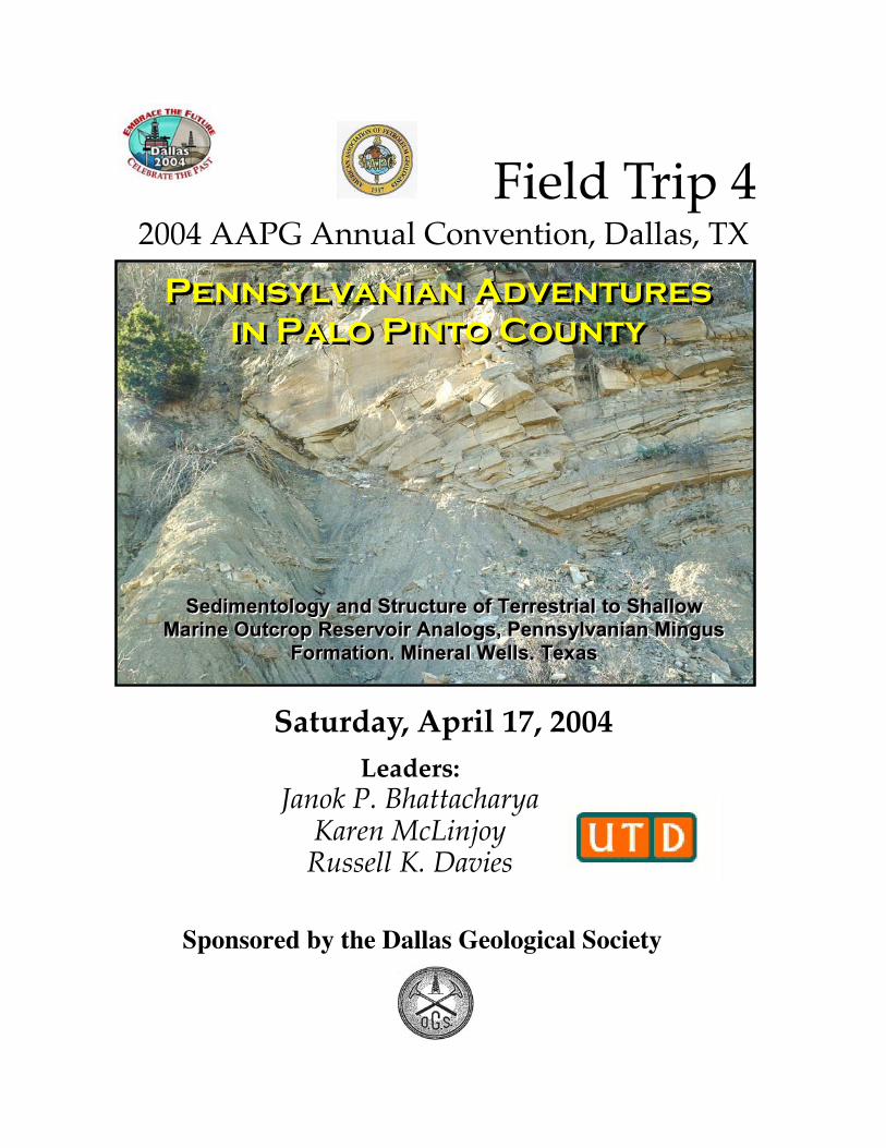
Field Trip 42004 AAPG Annual Convention, Dallas, TX
Saturday, April 17, 2004
Sponsored by the Dallas Geological Society
Leaders:Janok P. Bhattacharya
Karen McLinjoyRussell K. Davies
Pennsylvanian Adventuresin Palo Pinto County
Pennsylvanian Adventuresin Palo Pinto County
SSSeeedddiiimmmeeennntttooolllooogggyyy aaannnddd SSStttrrruuuccctttuuurrreee ooofff TTTeeerrrrrreeessstttrrriiiaaalll tttooo SSShhhaaallllllooowwwMMMaaarrriiinnneee OOOuuutttcccrrroooppp RRReeessseeerrrvvvoooiiirrr AAAnnnaaalllooogggsss,,, PPPeeennnnnnsssyyylllvvvaaannniiiaaannn MMMiiinnnggguuusss
FFFooorrrmmmaaatttiiiooonnn,,, MMMiiinnneeerrraaalll WWWeeellllllsss,,, TTTeeexxxaaasss
ii
Pennsylvanian Adventures in Palo Pinto County
AAPG Field Trip, Saturday, April 17th, 2004
Field Trip LeadersJanok P. Bhattacharya and Karen McLinjoy - Geosciences, University of Texas at
Dallas, P.O. Box 830688, Richardson, TX 75084, e-mail:[email protected]
Russell K. Davies - Rock Deformation Research, USA Inc., P.O. Box 2998, McKinney,TX, 75070-8998, e-mail: [email protected]
With contributions by:James A. MacEachern - Earth Sciences, Simon Fraser University, 8888 University
Drive, Burnaby, B.C., Canada, V5A 1S6, e-mail: [email protected] V. Aiken, Xueming Xu, and John Thurmond - - Geosciences, University of
Texas at Dallas, P.O. Box 830688, Richardson, TX 75084 [email protected]
Acknowledgements:In addition to the field trip leaders, field data in this report were collected by
Stephen Burns, Iulia Olariu, and Abrahim Shogar, as part of a UTD graduate course infacies analysis. Fiona MacEachern also aided with collection and identification of plantand body fossils. Chaz Duc kindly provided able assistance as a pilot and flew us alongthe outcrop so that we could take our photographs. The authors nevertheless take allresponsibility for any shortfalls or errors in interpretation.
Safety Considerations:The outcrops that we will visit include roadside exposures and railway cuts. Take
special care watching for traffic, especially if you cross the road or track. There arenumerous cacti, so take care where you walk. Long pants are recommended. Also, thereare rattlesnakes. If you climb an outcrop, avoid putting your hand above you. Usually thesnakes will give plenty of warning, but be on the lookout. Weather can be very variable,so bring a raincoat and hat. Temperature can be anywhere from freezing to in the 80’s. Ifit is warm, bring fluids on the longer hikes. The field trip will be moderately strenuous.We will have one hike up a hill and a 2-mile hike at the end of the day (1 mile each way).Wear appropriate footwear, preferably hiking boots. Sneakers have a tendency to beeasily punctured by cacti.
iii
Table of ContentsAcknowledgements: --------------------------------------------------------------- iiIntroduction ------------------------------------------------------------------------ 1Regional Setting --------------------------------------------------------------- 1Stratigraphy ------------------------------------------------------------------------ 6Stop 1. Jacksboro Roadcut I – Placid Shale Formation, Canyon Group 13Stop 2. Jacksboro Road cut II – Ranger Limestone Formation --------- 17Stop 3. Wizard Wells – SS3 member of the Placid Shale Formation ---- 18Stop 4. Incised Valley, Mineral Wells Radio Tower ------------------------- 20Stop 5. Lake Mineral Wells State Park ----------------------------------------- 24Stop 6. Brazos Railroad Cut off Bennett Road ------------------------------- 25
List of FiguresFigure 1. Location of Stops ------------------------------------------------------- 2Figure 2. Pangean Paleogeography ---------------------------------------------- 3Figure 3. Structural elements ---------------------------------------------- 4Figure 4. Outcrop belts ------------------------------------------------------- 5Figure 5. Stratigraphic cross section ------------------------------------- 7Figure 6. Strat. Chart ------------------------------------------------------- 8Figure 7. Paleogeographic evolution of the Canyon Group ---------------- 9Figure 8. Lithofacies map of the Placid Shale Formation------------------- 10Figure 9. Outcrop geology of Wizard Wells area ----------------------------- 11Figure 10. Outcrop geology of the Mineral Wells area ------------------- 12Figure 11. Measured Section, Jacksboro Road Cut ------------------- 14Figure 12. Photo of Jacksboro Road Cut ------------------------------------- 15Figure 13. Facies photos of stops 1 and 3 ------------------------------------- 16Figure 14. Wizard Wells photomosiac ------------------------------------- 19Figure 15. Tower Section, Mineral Wells ------------------------------------- 22Figure 16. Tower section photos ------------------------------------------------- 23Figure 17. Topo maps of the Brazos Railroad cut near Bennett ---------- 26Figure 18. Bedding diagram of Stop 6A ------------------------------------- 27Figure 19. Facies Photos of Brazos Railroad cut ---------------------------- 28Figure 20. Photomosaic and interpretation of synsedimentary faults ---- 31Figure 21. Steronet of Poles to Fault Planes --------------------------------- 32Figure 22. Measured section 3 ---------------------------------------------- 33Figure 23. Sandstone facies photos --------------------------------------------- 34Figure 24. Trace fossils photos ---------------------------------------------- 35Figure 25. Fault photos ------------------------------------------------------- 36Figure 26. Clay smear and fault gouge ------------------------------------------ 38
1
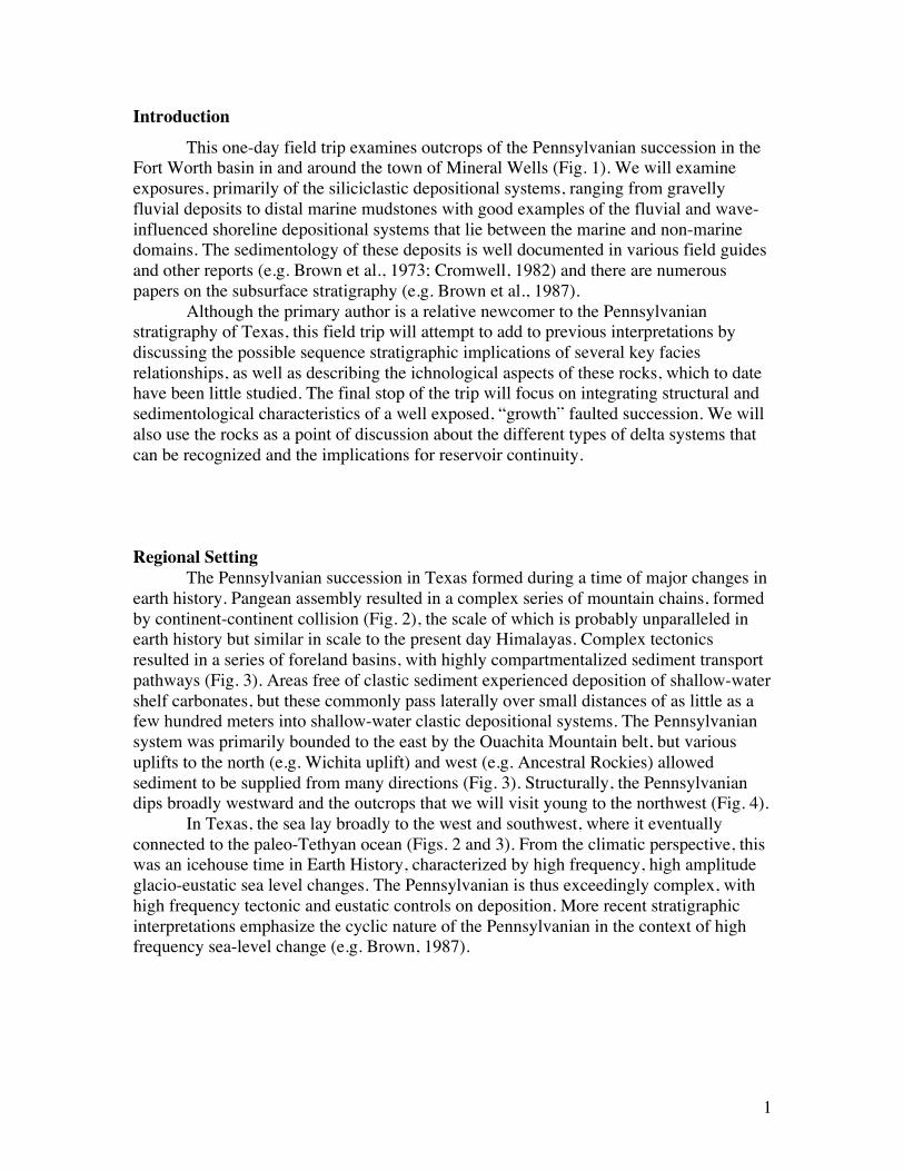
IntroductionThis one-day field trip examines outcrops of the Pennsylvanian succession in the
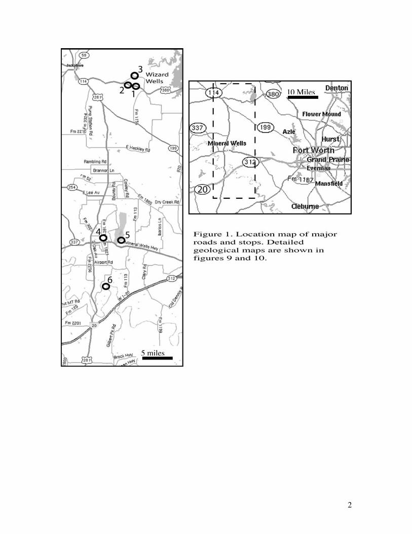
Fort Worth basin in and around the town of Mineral Wells (Fig. 1). We will examineexposures, primarily of the siliciclastic depositional systems, ranging from gravellyfluvial deposits to distal marine mudstones with good examples of the fluvial and wave-influenced shoreline depositional systems that lie between the marine and non-marinedomains. The sedimentology of these deposits is well documented in various field guidesand other reports (e.g. Brown et al., 1973; Cromwell, 1982) and there are numerouspapers on the subsurface stratigraphy (e.g. Brown et al., 1987).
Although the primary author is a relative newcomer to the Pennsylvanianstratigraphy of Texas, this field trip will attempt to add to previous interpretations bydiscussing the possible sequence stratigraphic implications of several key faciesrelationships, as well as describing the ichnological aspects of these rocks, which to datehave been little studied. The final stop of the trip will focus on integrating structural andsedimentological characteristics of a well exposed, “growth” faulted succession. We willalso use the rocks as a point of discussion about the different types of delta systems thatcan be recognized and the implications for reservoir continuity.
Regional SettingThe Pennsylvanian succession in Texas formed during a time of major changes in
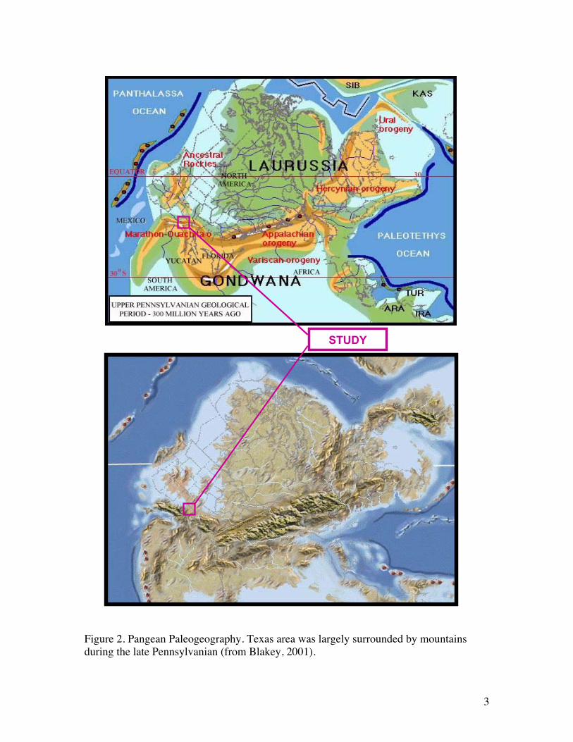
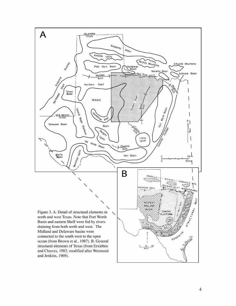
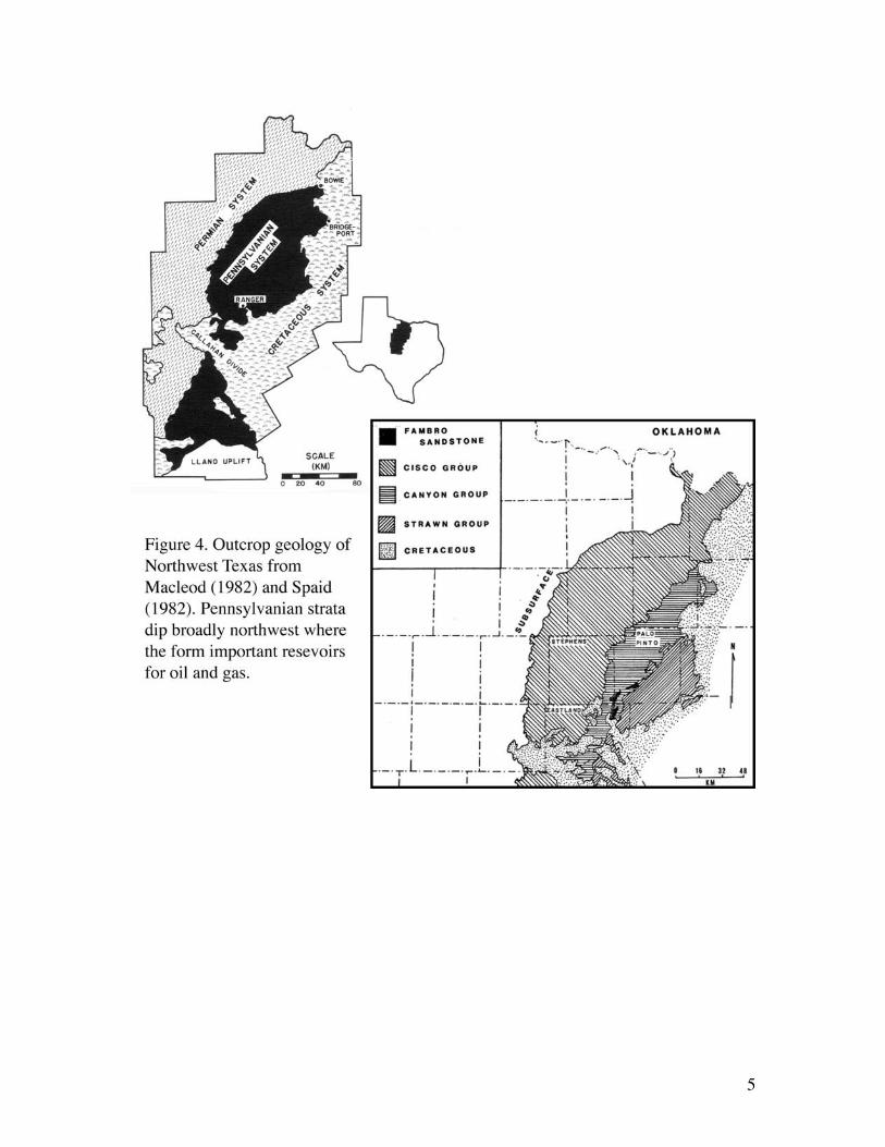
earth history. Pangean assembly resulted in a complex series of mountain chains, formedby continent-continent collision (Fig. 2), the scale of which is probably unparalleled inearth history but similar in scale to the present day Himalayas. Complex tectonicsresulted in a series of foreland basins, with highly compartmentalized sediment transportpathways (Fig. 3). Areas free of clastic sediment experienced deposition of shallow-watershelf carbonates, but these commonly pass laterally over small distances of as little as afew hundred meters into shallow-water clastic depositional systems. The Pennsylvaniansystem was primarily bounded to the east by the Ouachita Mountain belt, but variousuplifts to the north (e.g. Wichita uplift) and west (e.g. Ancestral Rockies) allowedsediment to be supplied from many directions (Fig. 3). Structurally, the Pennsylvaniandips broadly westward and the outcrops that we will visit young to the northwest (Fig. 4).
In Texas, the sea lay broadly to the west and southwest, where it eventuallyconnected to the paleo-Tethyan ocean (Figs. 2 and 3). From the climatic perspective, thiswas an icehouse time in Earth History, characterized by high frequency, high amplitudeglacio-eustatic sea level changes. The Pennsylvanian is thus exceedingly complex, withhigh frequency tectonic and eustatic controls on deposition. More recent stratigraphicinterpretations emphasize the cyclic nature of the Pennsylvanian in the context of highfrequency sea-level change (e.g. Brown, 1987).
2
5 miles
10 Miles
3
Figure 2. Pangean Paleogeography. Texas area was largely surrounded by mountainsduring the late Pennsylvanian (from Blakey, 2001).
STUDYAREA
4
5
6
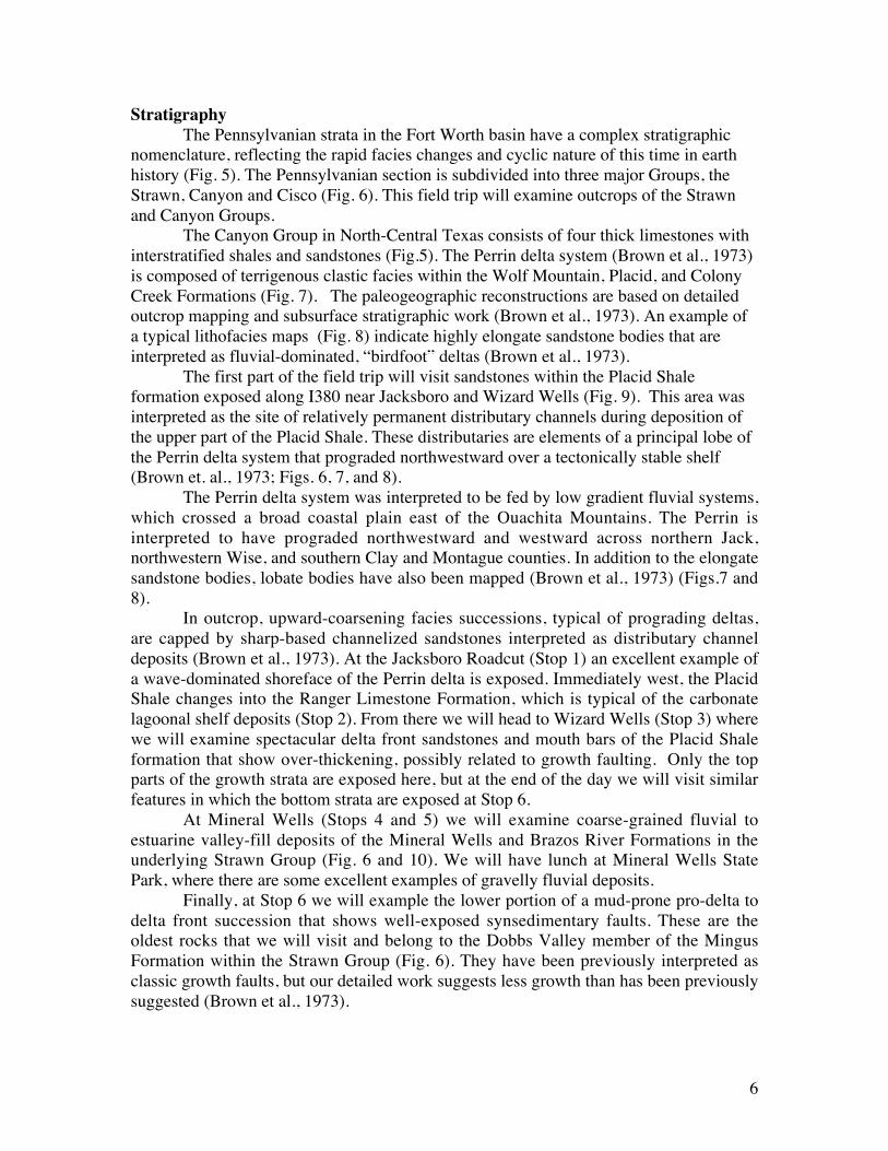
StratigraphyThe Pennsylvanian strata in the Fort Worth basin have a complex stratigraphic
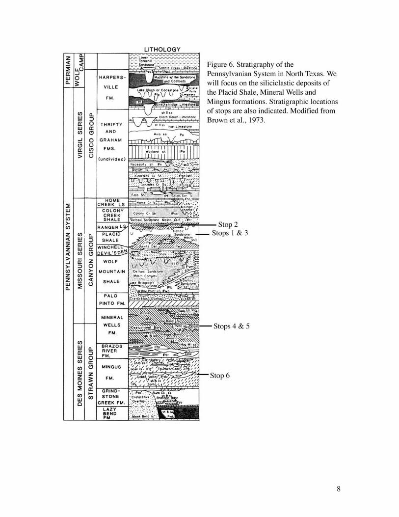
nomenclature, reflecting the rapid facies changes and cyclic nature of this time in earthhistory (Fig. 5). The Pennsylvanian section is subdivided into three major Groups, theStrawn, Canyon and Cisco (Fig. 6). This field trip will examine outcrops of the Strawnand Canyon Groups.
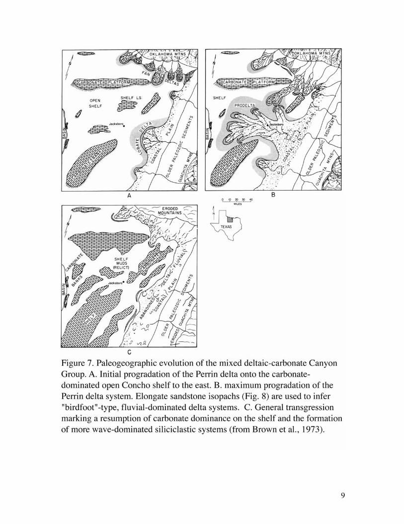
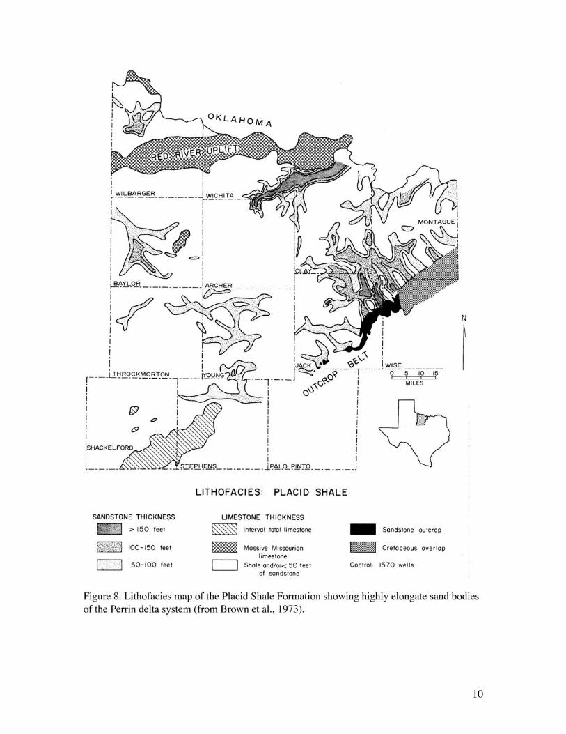
The Canyon Group in North-Central Texas consists of four thick limestones withinterstratified shales and sandstones (Fig.5). The Perrin delta system (Brown et al., 1973)is composed of terrigenous clastic facies within the Wolf Mountain, Placid, and ColonyCreek Formations (Fig. 7). The paleogeographic reconstructions are based on detailedoutcrop mapping and subsurface stratigraphic work (Brown et al., 1973). An example ofa typical lithofacies maps (Fig. 8) indicate highly elongate sandstone bodies that areinterpreted as fluvial-dominated, “birdfoot” deltas (Brown et al., 1973).
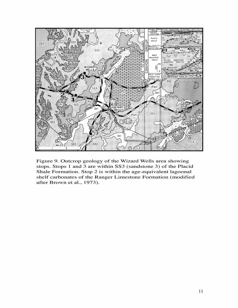
The first part of the field trip will visit sandstones within the Placid Shaleformation exposed along I380 near Jacksboro and Wizard Wells (Fig. 9). This area wasinterpreted as the site of relatively permanent distributary channels during deposition ofthe upper part of the Placid Shale. These distributaries are elements of a principal lobe ofthe Perrin delta system that prograded northwestward over a tectonically stable shelf(Brown et. al., 1973; Figs. 6, 7, and 8).
The Perrin delta system was interpreted to be fed by low gradient fluvial systems,which crossed a broad coastal plain east of the Ouachita Mountains. The Perrin isinterpreted to have prograded northwestward and westward across northern Jack,northwestern Wise, and southern Clay and Montague counties. In addition to the elongatesandstone bodies, lobate bodies have also been mapped (Brown et al., 1973) (Figs.7 and8).
In outcrop, upward-coarsening facies successions, typical of prograding deltas,are capped by sharp-based channelized sandstones interpreted as distributary channeldeposits (Brown et al., 1973). At the Jacksboro Roadcut (Stop 1) an excellent example ofa wave-dominated shoreface of the Perrin delta is exposed. Immediately west, the PlacidShale changes into the Ranger Limestone Formation, which is typical of the carbonatelagoonal shelf deposits (Stop 2). From there we will head to Wizard Wells (Stop 3) wherewe will examine spectacular delta front sandstones and mouth bars of the Placid Shaleformation that show over-thickening, possibly related to growth faulting. Only the topparts of the growth strata are exposed here, but at the end of the day we will visit similarfeatures in which the bottom strata are exposed at Stop 6.
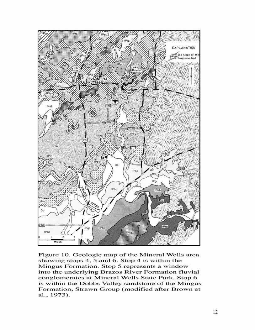
At Mineral Wells (Stops 4 and 5) we will examine coarse-grained fluvial toestuarine valley-fill deposits of the Mineral Wells and Brazos River Formations in theunderlying Strawn Group (Fig. 6 and 10). We will have lunch at Mineral Wells StatePark, where there are some excellent examples of gravelly fluvial deposits.
Finally, at Stop 6 we will example the lower portion of a mud-prone pro-delta todelta front succession that shows well-exposed synsedimentary faults. These are theoldest rocks that we will visit and belong to the Dobbs Valley member of the MingusFormation within the Strawn Group (Fig. 6). They have been previously interpreted asclassic growth faults, but our detailed work suggests less growth than has been previouslysuggested (Brown et al., 1973).
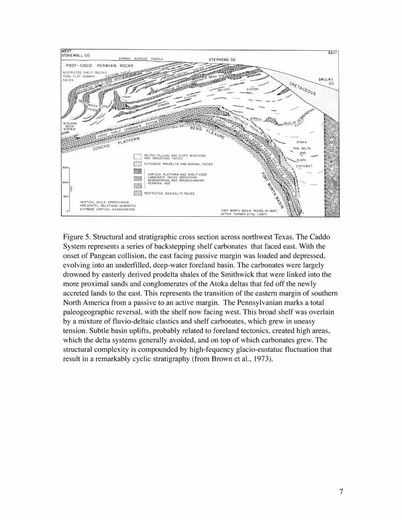
7
8
9
10
11
12
13
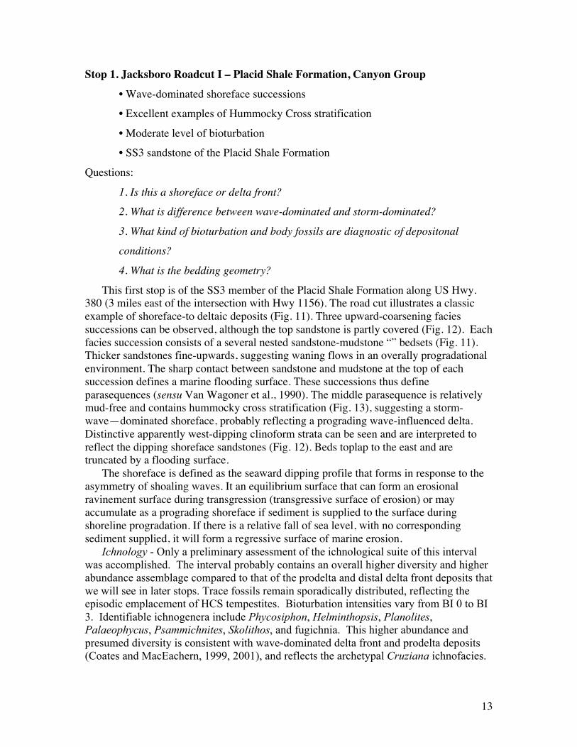
Stop 1. Jacksboro Roadcut I – Placid Shale Formation, Canyon Group• Wave-dominated shoreface successions• Excellent examples of Hummocky Cross stratification
• Moderate level of bioturbation• SS3 sandstone of the Placid Shale Formation
Questions:
1. Is this a shoreface or delta front?
2. What is difference between wave-dominated and storm-dominated?
3. What kind of bioturbation and body fossils are diagnostic of depositonal
conditions?
4. What is the bedding geometry?
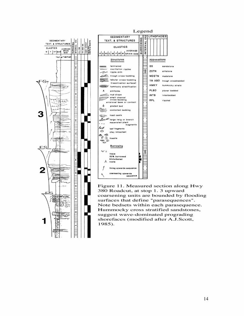
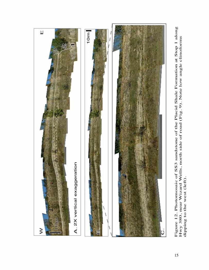
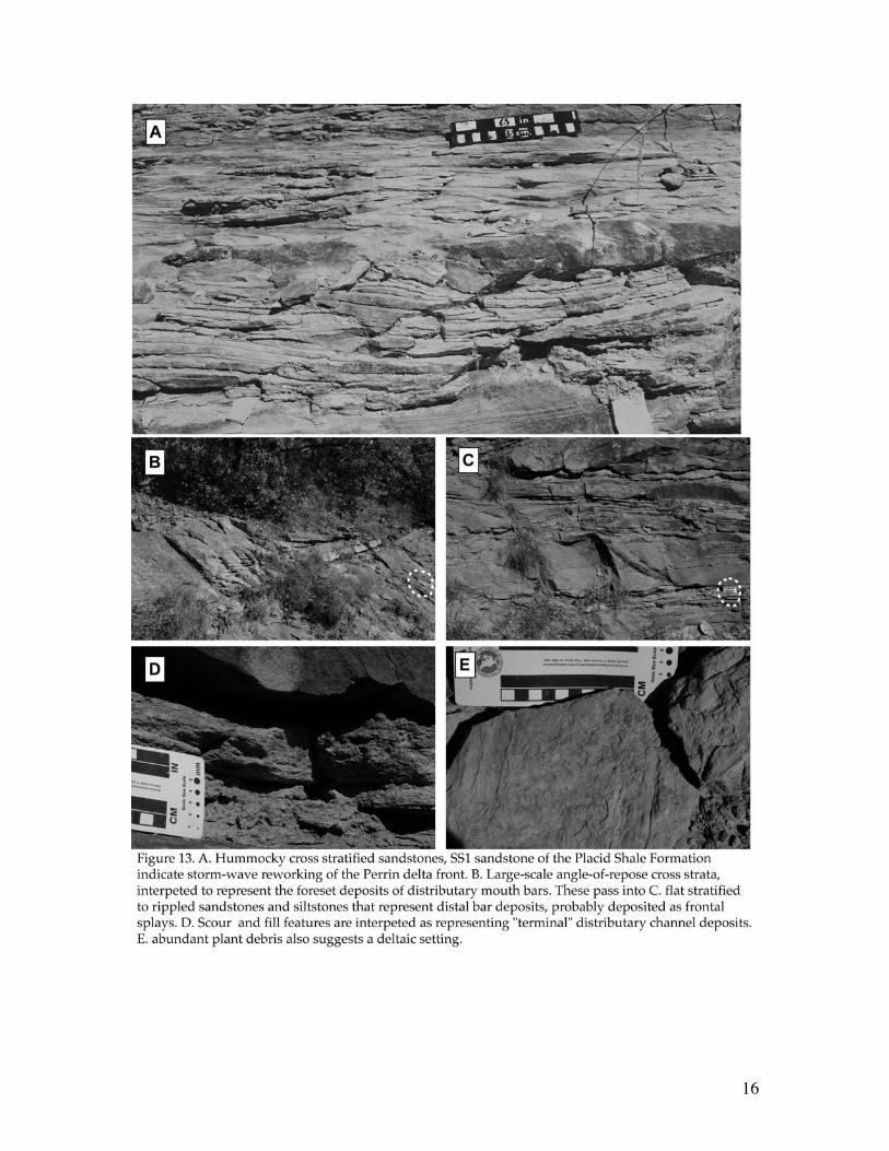
This first stop is of the SS3 member of the Placid Shale Formation along US Hwy.380 (3 miles east of the intersection with Hwy 1156). The road cut illustrates a classicexample of shoreface-to deltaic deposits (Fig. 11). Three upward-coarsening faciessuccessions can be observed, although the top sandstone is partly covered (Fig. 12). Eachfacies succession consists of a several nested sandstone-mudstone “” bedsets (Fig. 11).Thicker sandstones fine-upwards, suggesting waning flows in an overally progradationalenvironment. The sharp contact between sandstone and mudstone at the top of eachsuccession defines a marine flooding surface. These successions thus defineparasequences (sensu Van Wagoner et al., 1990). The middle parasequence is relativelymud-free and contains hummocky cross stratification (Fig. 13), suggesting a storm-wave—dominated shoreface, probably reflecting a prograding wave-influenced delta.Distinctive apparently west-dipping clinoform strata can be seen and are interpreted toreflect the dipping shoreface sandstones (Fig. 12). Beds toplap to the east and aretruncated by a flooding surface.
The shoreface is defined as the seaward dipping profile that forms in response to theasymmetry of shoaling waves. It an equilibrium surface that can form an erosionalravinement surface during transgression (transgressive surface of erosion) or mayaccumulate as a prograding shoreface if sediment is supplied to the surface duringshoreline progradation. If there is a relative fall of sea level, with no correspondingsediment supplied, it will form a regressive surface of marine erosion.
Ichnology - Only a preliminary assessment of the ichnological suite of this intervalwas accomplished. The interval probably contains an overall higher diversity and higherabundance assemblage compared to that of the prodelta and distal delta front deposits thatwe will see in later stops. Trace fossils remain sporadically distributed, reflecting theepisodic emplacement of HCS tempestites. Bioturbation intensities vary from BI 0 to BI3. Identifiable ichnogenera include Phycosiphon, Helminthopsis, Planolites,Palaeophycus, Psammichnites, Skolithos, and fugichnia. This higher abundance andpresumed diversity is consistent with wave-dominated delta front and prodelta deposits(Coates and MacEachern, 1999, 2001), and reflects the archetypal Cruziana ichnofacies.
14
15
16
17
Stop 2. Jacksboro Road cut II. – Ranger Limestone FormationHwy. 380 (2.9 miles east of Hwy 1156).
• Skeletal packstones of the Ranger Limestone Formation
• Carbonate lagoonal shelf• Abrupt lateral transition from clastic into carbonate environments
Questions to ponder:1. Would this make a good marker bed?
2. What controls the abrupt lateral transition from wave-dominated sandy
shorefaces into a shelf limestone?
3. Why do the clastic sediments avoid this area?
Driving a few hundred meters west (Fig. 9) we observe a complete change in faciesand lithology. The Placid Shale siliciclastics are gone and instead we observe carbonatesof the Ranger Limestone Formation. The carbonates are medium-bedded, grayfossiliferous mudstones and wackestones, indicating a shallow shelfal setting.Stratigraphic cross sections (e.g. Fig. 6) show the Placid Shale interfingering with theRanger Limestone, showing that that are time equivalents.
18
Stop 3. Wizard Wells – SS3 member of the Placid Shale Formation• Over-thickened, growth faulted strata• Distributary mouth bar and terminal distributary channel sandstones
• Fluvial-dominated Perrin delta frontQuestions:
1. What causes growth faulting?
2. What arethe main sandy architectural elements?
3. Is there a relationship between the faults and the sandy elements?
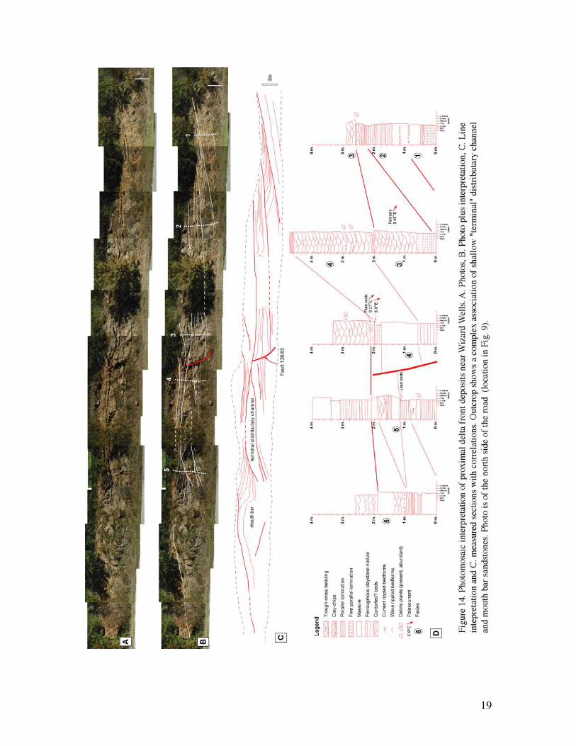
This outcrop is on FM 1156, about 2.6 miles E of 380, W of Wizard Wells (location in Fig. 9). The outcrop shows a good example of proximal delta front facies ofthe Perrin delta system. The photomosiac (Fig. 14) shows well-developed growth stratawith one well-exposed fault in the middle of the outcrop. The measured sections showlarge, meter-thick medium to coarse-grained cross strata (Fig. 13B), interpreted torepresent the front of distributary mouth bars that were building approximately southeast.The trough-cross beds pass laterally into parallel-stratified beds (Fig. 13C) interpreted asthe distal toes of the mouth bars. Individual sandstone beds likely represent frontalsplays. Despite a generally northwest progradation direction for the Perrin delta, locally,distributary channels (Fig. 14) were oriented at high angles to the generally mapped,North-South shoreline orientation.
Trough cross bedded medium to coarse-grained distributary channel sandstonesalso show large scour and fill structures (Fig. 14) with load cast and flute cast common atthe base (Fig. 13D). Mud-chip conglomerates, as well as abundant plant stems andleaves, are also common (Fig. 13E). All these observations suggest a relatively high-energy proximal delta front environment characterized by rapidly decelerating flows andhigh sedimentation rates.
Studies of similar growth strata in the Cretaceous Ferron sandstone member inUtah (Bhattacharya and Davies, 2001) show that growth faults are commonly initiated bythe rapid deposition of mouth bars, such as is also seen here. At stop 6 we will examinethe lower portion of a series of possible growth faults along the Brazos River. The toppart of that exposure is difficult to get to, so this outcrop may give you an idea of what ishappening at the top of the faults at Stop 6.
19
20
Stop 4. Incised Valley, Mineral Wells Radio Tower• Stacked upward coarsening marine facies succession capped by possible incisedvalley
• Valley fill is about 6m (20 feet) thick• Floored by a pebble conglomerate
• Tidally-influenced cross bedding with a low diversity trace fossil suite
• East Mountain Shale member of the Mineral Wells FormationQuestions:
1. Is this a distributary channel, fluvial channel, or incised valley?
2. How far seaward could the shoreline facies fed by the channel lie?
3. What is the 3D geometry of this sandstone body and what are the implication of
the depositional model for reservoir heterogeneity and extent?
From Wizard Wells we will head back to Hwy 380 until we reach Hwy 281. Wewill drive about 20 miles south to the town of Mineral Wells stopping at the RadioTower. This outcrop is virtually on the northeast side of downtown Mineral Wells (Fig.10). There is excellent fossil hunting in the mudstones at the base of the cliff. For themore adventurous, we will hike about 100 feet up to the base of the sandstone at the topof the tower. There is a path up, but there are numerous cacti on the climb up so be varycareful. You won’t get into serious trouble, but the cacti are sharp. At the top, the way upis narrow and moderately difficult to navigate. Be very careful of people below you,especially when you reach the exposed rock at the top.
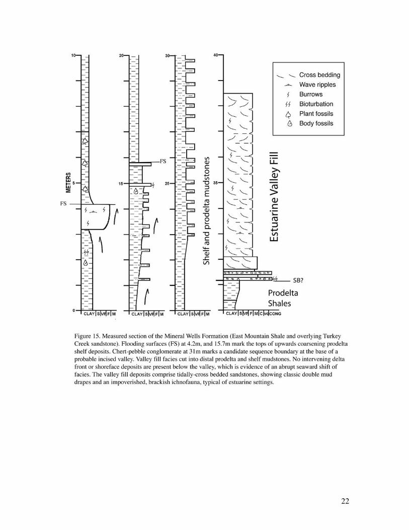
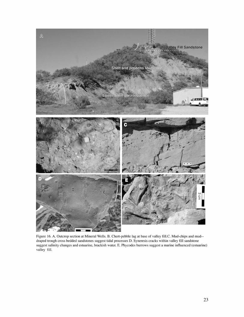
The measured section (Fig. 15 and 16) shows two stacked coarsening-upwardshelf parasequences capped by a sharp-based pebbly sandstone. The mudstones containwell-preserved brachiopods, crinoid stems and other typical Pennsylvanian body fossils,suggesting fully marine conditions. The ichnofacies are described below.
These mudstones are sharply overlain by a 20m medium to coarse-grained pebblysandstone floored by a chert-pebble and mud-chip lag conglomerate (Fig. 16B),suggesting an erosional base, although the outcrop is not wide enough to observe adistinctive cut-bank or valley-margin. Internally, the sandstones are trough cross bedded(Fig. 16C). Cross beds contain numerous thin mud laminae and mud drapes, suggestiveof tides. Paleocurrents were difficult to measure but appear to indicate flow towards thewest. Syneresis cracks can be seen on bedding planes and are suggestive of brackishwater conditions. The trace fossils (see below) also suggest a brackish, estuarine typesetting.
Many sharp, erosionally-based, fining-upward sandstone deposits, such asexposed here, have been historically interpreted as distributary channel deposits. Theabrupt juxtaposition of conglomerate over offshore prodelta mudstones suggests a rathermore abrupt seaward shift in facies, than would be expected during the normalprogradation of distributary channels over a delta front. The thickness of the overlyingdeposit, the top of which is not observed, suggests deep incision of at least 7m, and
21
possibly more. The suggestion of tidal cross bedding and brackish water conditionsindicates that this sandstone is an estuarine incised valley fill, rather than a distributarychannel. Such abrupt facies changes are quite typical of the Pennsylvanian, and arepredicted in icehouse times.
Ichnofacies - The succession shows two principal ichnological suites: a suiteassociated with the finer-grained lower portion of the succession, and an upper suiteassociated with the overlying sandstone at the top of the succession. The lower suite ismore diverse and bioturbation is both uniformly distributed and intense (BI 3-5; typically4). Sandstone interbeds display mud lined (locally siderite cemented) vertical shaftsattributable to Skolithos, and less commonly, possibly Diplocraterion. Possible subtlefugichnia (escape traces) are also present. Some beds also contain hematite-stainedsideritic small-diameter Thalassinoides mazes. The silty mudstones and muddy siltstonesdisplay the higher bioturbation intensities (BI 4-5) and contain Chondrites, Phycosiphon,Planolites, Palaeophycus, Thalassinoides, and Helminthopsis.
The suite developed reflects the alternation from a low diversity expression of theSkolithos ichnofacies, to a fairly high diversity expression of the archetypal Cruzianaichnofacies. This corresponds to the mixed Skolithos-Cruziana ichnofacies, consistentwith distal marine conditions subject to episodic deposition consistent with a storm-influenced shelf or offshore environment. Preliminary assessment of the assemblageshows no marked evidence of impoverishment, and therefore, no indication ofpaleoenvironmental stress, suggesting that sedimentation rates were generally lower, andsuspended sediment at the bed and in the water column were not pronounced.
The upper sandstone unit displays few identifiable trace fossils, most confined to thetops of bedding planes. Bioturbation is of very low intensity (BI 0-1), with ichnogeneraof low diversity and abundance. Trace fossils are sporadically distributed through theinterval. Traces are generally poorly preserved and correspond to unidentifiedlocomotion structures of gastropods and possibly bivalves. Planolites, and possiblyCurvolithus are present as well. The suite is consistent with rapid deposition, mobilebedforms, and reduced salinity conditions, consistent with estuarine incised valleydeposition. The local preservation of syneresis cracks may support reduced salinityconditions. The paucity of identifiable forms precludes assignment to a particularichnofacies, though the identifiable forms are typical of the Cruziana ichnofacies.
22
23
24
Stop 5. Lake Mineral Wells State Park – Brazos River Fm. Conglomerates• Coarse-grained fluvial conglomerates, sourced from Arkansas Novaculite.• Eroded from Ouachita facies (Dev-Miss)
• Probable incised valley-fill depositsWe will now drive about 5 miles east to Mineral Wells State Park. Minerals Wells
State Park is a popular area for rock climbers because of the steep cliffs. These cliffs cutdown into fluvial conglomerates of the Brazos River Formation but are likely older thanthe pebbly sandstones observed at Stop 4.
We have no measured section here, but you will see good examples of cross-bedded channel and bar deposits. The nearly 10 meter thick conglomerates are likelymultistorey, consisting of numerous amalgamated channel deposits. Some individualcross strata are over 1 meter thick, suggesting large-bar-scale bedforms.
The very course-grained nature of these deposits led Erxeleben (1973 in Brown etal. 1973) to suggest that these are incised valley fills. Certainly they represent aconsiderably coarser facies than we have observed on the trip so far.
In general, sorting tends to decrease in fluvial deposits as grain size increases.This results as a natural consequence of bed-scale processes. Marine shorefaceconglomerates tend to show far better sorting than fluvial conglomerates (Hart and Plint,1989).
25
Stop 6. Brazos Railroad Cut off Bennett RoadStop 6A: Undeformed distributary channels and ravined delta front sandstone.
• Distributary Channels
• Ravined delta front
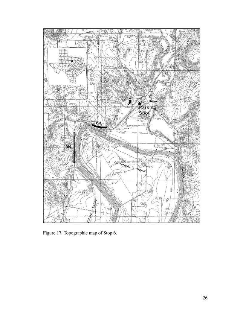
Leaving Mineral Wells State Park we will head back to Hwy 180 heading west forabout 1.5 miles. We will then drive south on 1195 for about 3 miles until we hit BennettRoad. We will turn left, heading southeast on Bennett Road. We will stop near a Brickfactory, next to the Railroad. We will leave the Bus and take about a 1 mile hike downthe tracks (Fig. 17). Please exercise care on the railroad. Trains come through regularly inboth directions. Please try and stay off the tracks as much as possible.
These strata form part of the Dobbs Valley sandstone member of the MingusFormation (Figs. 6 and 10) and are stratigraphically the oldest rocks that we will visit.
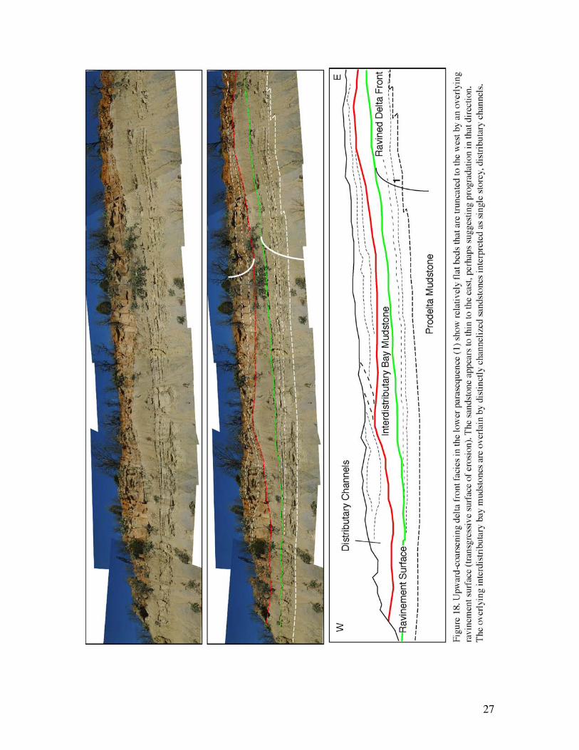
About half a mile down the road is a well-exposed, primarily west-east orientedcliff (Fig. 18). At the base is an upward-coarsening delta front sandstone. Beds within thelower parasequence are truncated to the west (left). Truncation is likely related to waveerosion (ravinement) during transgression of the delta top. The overlying bay fillmudstones are in turn overlain by red-weathering sandstones that exhibit a sharp,undulating, erosional base. Dipping beds within the sandstone mark bar accretionsurfaces and the sandstone is interpreted as a migrating distributary channel deposit. Theaccretion surfaces extend from the top to the base of the sandstone body, suggesting asingle storey sandstone, unlike the thicker cross bedded valley fill deposits seen at theother stops.
Although this cliff is too steep to climb safely, large blocks of the channel fillsandstone can be examined along the railroad and show some spectacular examples ofwell-preserved typical Pennsylvanian fossil plants (Fig. 19).
We do not have any detailed measured sections of this cliff.
Stop 6B – Synsedimentary Faults in a prodelta to delta front succession• Possible growth faulted delta front and channel mouth bar facies
• Dobbs valley sandstone of the lower Mingus Formation (Strawn Group)
Questions:
1. Are these listric or normal faults?
2. How much growth is evident?
3. What would the effective properties of these faults be?
4. How does facies reflect the structure?
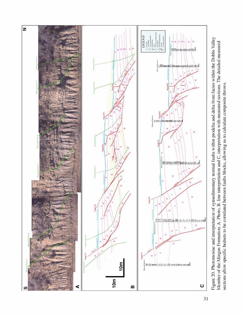
As we continue another half mile down the track we will come upon a north-southoriented cliff about 100m in length (Fig. 17) that shows spectacular examples ofsynsedimentary growth faults (Fig. 20). A photomosaic and 6 measured sections allowsus to make an integrated analysis of sedimentation and development of the structures.
26
27
28
29
This area is a haven for rattlesnakes and there is always a risk of falling rocks. Takespecial care on these cliffs, and if you clamber up, make absolutely sure that there is noone below you. Also, do not climb the fence, as this will trigger an alarm and we will bevisited by the UPR safety inspectors. If you want to examine the exposures close-up, gothrough the gates.
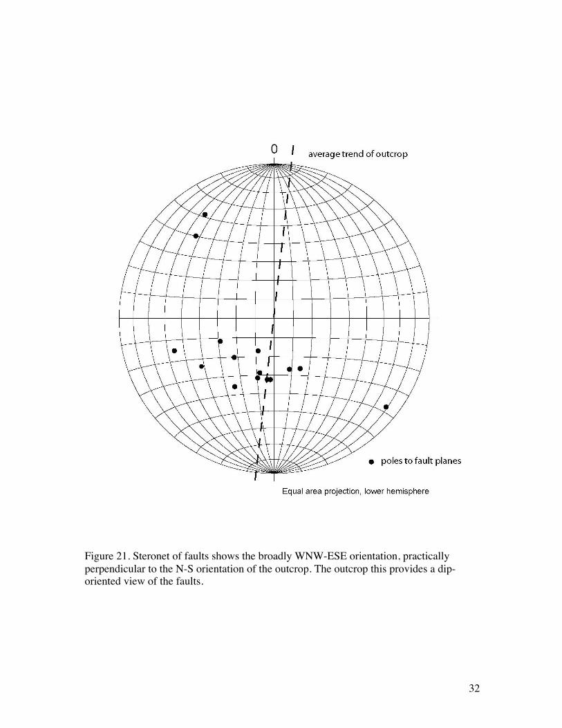
These faults have been previously interpreted as classic growth faults by Brown et al.(1973). The outcrop is oriented nearly perpendicular to the fault strikes (Fig. 21). Thisstudy demonstrates that although the faults are listric, the growth occurs only locallywithin a 30 meter upward-coarsening, mudstone to sandstone facies succession.
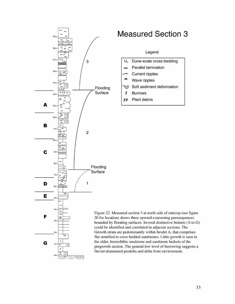
The succession in this outcrop records progradation of a small delta lobe, whichoverlies distal prodelta facies of the lowest Mingus Shale and underlies interdistributarybay mudstones (Fig. 22).
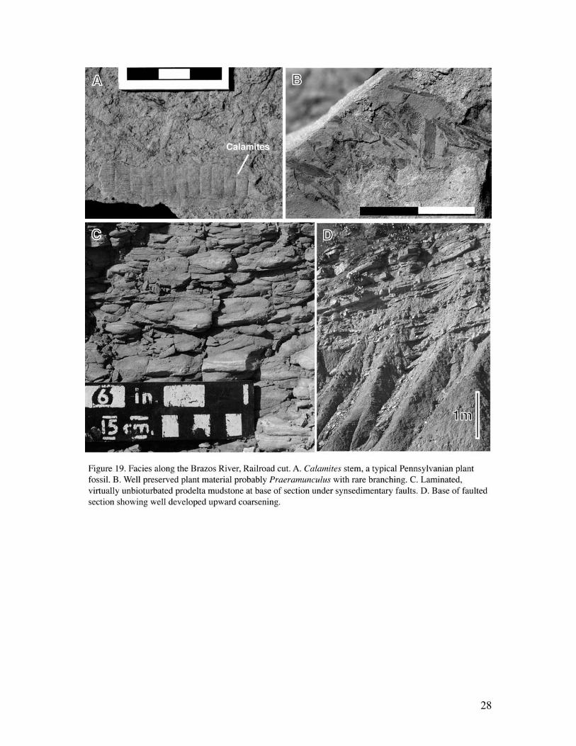
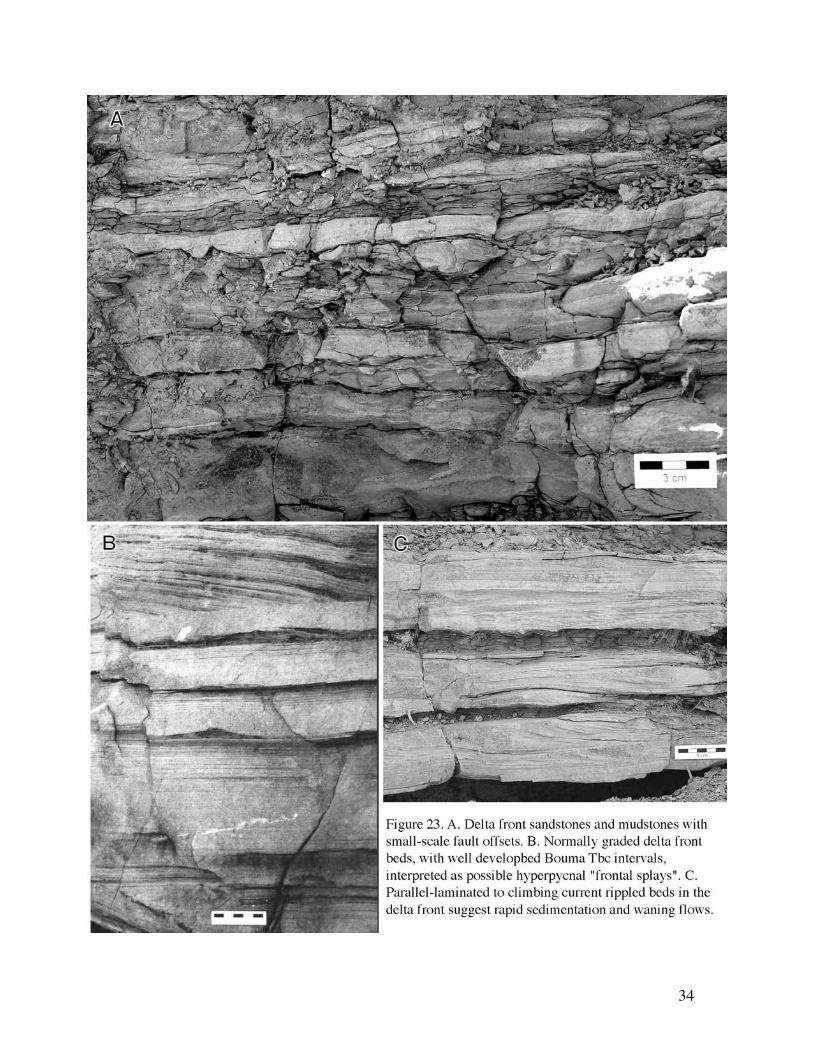
Sedimentology and stratigraphy- Approximately 9 meters of the base of the outcropcomprises proximal prodelta facies (Brown, et al., 1973) in which, laminae of very finesandstone are observed within a silty mudstone (Figs. 19C, 22, 23A). Plant material isobserved in both the shale and sand beds. Material has slid down from the overlyingdelta-front sandstone facies and is seen in flow rolls and rotated sandstone blocks. Totalsand increases upwards through the section (Fig. 19D).
Sandstones are predominantly structureless and graded to current rippled (Fig. 23B and C). Climbing ripples suggest relatively rapid sedimentation and the graded beds areinterpreted to possibly represent hyperpycnal type delta front turbidites. These may formas frontal splays flowing down a steep front of the associated mouth bars.
Distinctive bedsets (labeled A through G) could be identified across the outcropbelt. Unit G is characterized by a distinctive doublet that can be idnetified in each of thefault blocks. The major growth section appears to be within the relatively sandy facies ofunit between faults F2 and F3 (Fig. 20).
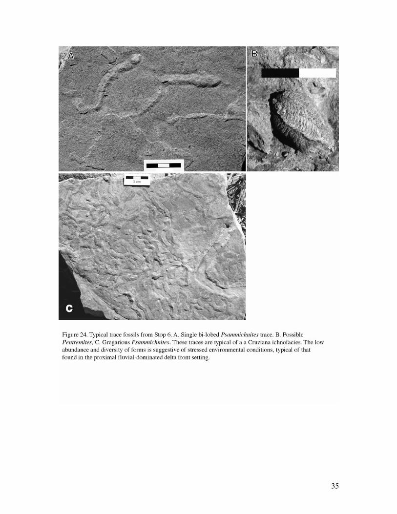
Ichnology and Paleobotany - Like most prodelta and distal delta front complexes, thisinterval is characterized by highly sporadic distributions of trace fossils, and generallylow to absent bioturbation intensities (BI 0-1, Fig. 19C and 24). Traces, where preserved,are more typically concentrated at the bases of non-erosively emplaced event beds, and atthe tops of event beds. Along these interfaces, bioturbation intensities may reach BI 3,but typically BI 1-2. The assemblages produced, though of low abundance and generallylow diversity, are nonetheless, marine in character. The trace fossil suite consists of verylow numbers of Planolites, Psammichnites, Palaeophycus (originally referred toTerebellina), Lockeia, Skolithos, Phycosiphon (very rare), and Chondrites (veryrare)(Fig.24). A possible meniscate-filled horizontal tube was tentatively identified asTaenidium. Some bedding planes show locomotion structures of bivalves andgastropods, but are too poorly preserved to assign ichnogenera designations.
The suite is consistent with deposition in a marine, though stressful environment. Thepaucity of bioturbation reflects high sedimentation rates, episodic deposition, andpossible high suspended-sediment concentrations in the water and on the bed. Somesubstrates may reflect soup-ground conditions, limiting both the ability of infaunalorganisms to inhabit the area, and the preservation potential of any structures that weredeveloped there. The assemblage corresponds to a highly impoverished expression of the
30
archetypal Cruziana ichnofacies, and is typical of prodeltaic and delta front settings,particularly those that show strong river domination. Similar suites have been identifiedfrom the prodelta of river-dominated lobes in the Dunvegan Formation and the basalBelly River Formation of west-central Alberta, Canada (Gingras et al., 1999; Coates andMacEachern, 1999, 2001)
This section also contains a large number of allochthonous plant fragments (Fig. 19Aand B), some well preserved and identifiable. Included in this assemblage arePraeramunculus-like detritus with rare branching preserved; fragments of lycopods (clubmosses); cone scales probably representing up to 3 taxa; and Equisetum-like stems (noleaves attached). Leaves representing 2 taxa are also represented, one of which appearscompound and fern-like. One large floral specimen was encountered that may reflect apossible fruit body.
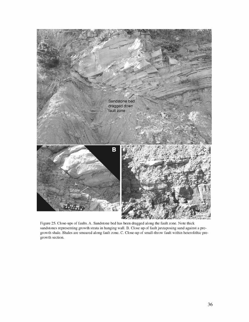
Faulting - Four fault zones occur 5 to 10 meters apart across the outcrop (Fig. 20) andare concave to the north with paleocurrents flowing approximately southeast tonorthwest. The faults strike broadly WNW-ESE and dip to the north (Fig. 21). Manysmaller synthetic and antithetic faults are also observed (e.g. Figs. 23A, 25C). Sand andshale smears and termination of faults within the succession show that faults were activeduring deposition (Fig. 25).
The fault zones were active at different times. Fault F5, for example, stopped movingbefore the formation of the major flooding surface, whereas Faults 1 to 4 were activeafter the lowest delta lobe was flooded. It also appears that the faults migrated fromnorth to south up depositional dip, versus initiating in a progressively more distaldirection as the delta prograded. Similar complex fault history was also observed in theCretaceous Ferron sandstone (Bhattacharya and Davies, 2001).
In the hanging wall of fault F1, sand appears to be dragged down the fault zone (Fig.25A). Offset along the faults ranges from as little as 0.5 meters near fault terminations upto 10meters across longer faults. The base of the faults occurs in distal prodelta mudswith some soft-sediment deformation. Composite throw is about 30 meters across all thefaults.
Measured sections (Fig. 22) show the sedimentologic variations associated withdifferent parts of the major faults, which allows for an evaluation of the relationshipbetween fault timing and depositional processes. Although exposure is poor toward thetop, we infer that deposition of thick-bedded delta mouth bar sands may be responsiblefor initiating some of the growth faults, such as Fault F5, similar to the fault observed atWizard Wells (Stop 3). An over-thickened sandy section B, in the hanging wall adjacentto Fault F2 (Fig. 20) likely initiated the movement of that fault, although the faultcontinues to move after flooding of the delta
Our preliminary interpretations suggest that the faults in the Mingus Formation mayform by a combination of mechanism, including slumping associated with the failure ofan unstable slope, as well as initiation by deposition of thick delta front sands in thehanging walls.
31
32
Figure 21. Steronet of faults shows the broadly WNW-ESE orientation, practicallyperpendicular to the N-S orientation of the outcrop. The outcrop this provides a dip-oriented view of the faults.
33
34
35
36
37
Fault Rocks: Description and Analysis
DescriptionFault rock is a term for the internal structure of fault zones. Following Fisher &
Knipe (1998) a threefold subdivision of fault rock types is based on the percent of claywithin the protolith that is incorporated into the fault zone. The fault rock types arecataclasites which contain <15% clay, phyllosilicate framework fault rocks (PFFR) with15-40% clay and clay smears with >40% clay. The sealing potential or amount ofhydrocarbon column supported by the fault rocks is calibrated to these fault rock types.The growth faults along the railroad cut in the Mingus formation cut primarily a shaleand sand section. In this case, we expect primarily the development of cataclasites andclay smears.
Cataclasites form in clean sandstones by deformation-induced grain fracturingand porosity collapse. These fault rocks have relatively low seal potential compared withmore clay-rich fault rocks, particularly if faulting took place at shallow to moderate burialdepths (<1.5km). Cataclasites have permeabilities reduced by between 1 and 6 orders ofmagnitude compared with their host sandstones.
The faults in the growth fault section are interpreted to develop in shallow waterdepths when the sediments are weak. Faults formed in poorly consolidated cleansandstones form disaggregation seams by grain rolling and sliding but with little or nofracturing. Disaggregation seams are more likely to have permeabilities and capillaryentry pressures comparable with their host sediment, although ’cleaning’ of graincontacts by abrasion during grain-sliding can be important in that clean quartz grainboundaries act as sites for the preferential nucleation of quartz cement. This effectbecomes more pronounced at temperatures greater than 90oC. With a normal thermalgradient of approximately 30oC/km, the section would have to be buried to greater than 3km for significant quartz cements to have developed along the growth faults in theMingus Fm. How deep do we expect this section to have been buried? Could we havedeveloped cataclasis across these fault zones?
Phyllosilicate framework fault rocks have petrophysical properties controlledby the presence of fine-grained phyllosilicates. These have heterogeneous microfabricsdominated by domains where a framework comprised of mixed orientated phyllosilicateplates is present. These fault rocks experienced a reduction in porosity as a result of threeprocesses. First, during deformation, phyllosilicates were mixed with framework grainsresulting in a replacement of macroporosity with microporosity. Second, followingdeformation, some of these faults experienced enhanced grain-contact quartz dissolutiondue to the presence of phyllosilicates at grain contacts. Third, in some cases, cataclasiscontributes to porosity reduction in these fault rocks. These fault rocks have far lowerpermeabilities and higher entry pressures compared to their host sandstones and are likelyto form significant barriers to fluid flow. In general, the sands in the Mingus formationare expected to have a low clay content, which would minimize the development of thesetypes of fault rocks. Is there any field evidence of more clay rich rocks that may alsoserve as an impure sandstone or poorer quality reservoir?
Clay smears are fault rocks that contain coherent domains of alignedphyllosilicates, the majority of which form in sediments containing over 40% total finegrained phyllosilicates. Such clay smears are likely to have a high seal potential with
38
capillary entry pressures of >1000psi. The shales between the sands in the Mingussection are good candidates for smear between two juxtaposed sands. Do you see anyevidence for these smears in the outcrop?
AnalysisImportant controls on fault seal include the fault rock types and their sealing
capacity, but also the distribution of the fault rocks across the fault surface. Severalalgorithms have been developed to estimate the distribution of the clay across the faultsurface. The clay percent is linked to the fault rock types defined above.
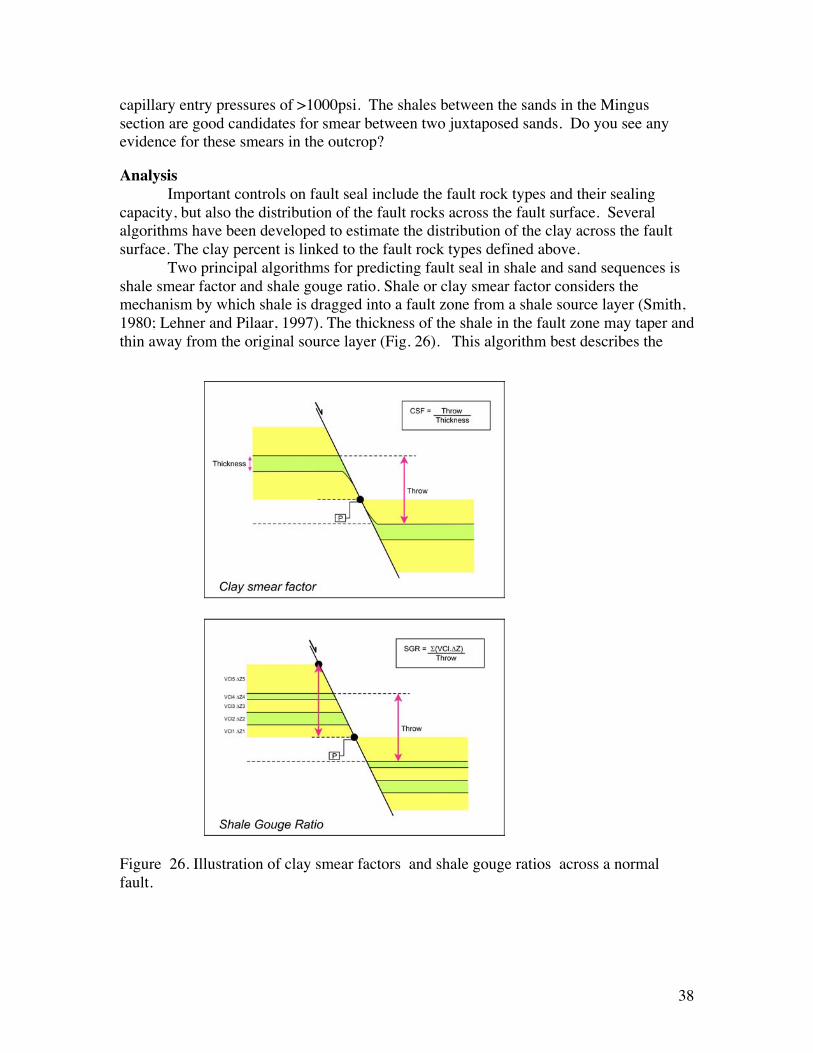
Two principal algorithms for predicting fault seal in shale and sand sequences isshale smear factor and shale gouge ratio. Shale or clay smear factor considers themechanism by which shale is dragged into a fault zone from a shale source layer (Smith,1980; Lehner and Pilaar, 1997). The thickness of the shale in the fault zone may taper andthin away from the original source layer (Fig. 26). This algorithm best describes the
Figure 26. Illustration of clay smear factors and shale gouge ratios across a normalfault.

39
process when the sediments are weak and mobile. The predictive algorithm fordetermining the distribution of shale smear as a sealing mechanism in a fault zone definesthe length of the continuous or unbroken taper, or characteristic sealing length, versus thediscontinuous taper that is deemed nonsealing (Yielding et al., 1997; Lehner and Pilaar,1997; Lindsay et al., 1993). The clay smear factor, CSF, is the ratio of the throw to thethickness. The Rock Deformation Research group has determined that a CSF of 3, whichcorrelates to a smear thickness equal to the source bed thickness, is an average value thatcan be applied as a rule of thumb in an undercalibrated region.
Shale gouge describes a mechanism of uniform mixing of shale from the hostrock with other lithologies in the fault zone (Yielding et al., 1997). This algorithm appliesprincipally to rocks that are more lithified. Predictive algorithms for shale gougecalculate the ratio or percent of shale in the fault zone at each point along the faultsurface. The shale gouge is generally calculated as a ratio of shale thickness to faultthrow, T. The percentage of shale, Si, in a lithological unit times the layer thickness, Hi,summed over an interval of host rock for each layer displaced past a point on the faultdefine a shale gouge ratio:
where n is the number of layers. This algorithm is generally considered to representuniform mixing of the clays and sands. The March 2003 AAPG Bulletin on fault sealedited by Davies and Handschy offers a more comprehensive review of the fault sealprocess, calibration and prediction.
40
References:
Bhattacharya, J.P., and Davies, R.K., 2001, Growth faults at the prodelta to delta–front transition,Cretaceous Ferron Sandstone, Utah. Marine and Petroleum Geology. V. 18, p. 525-534.
Blakey, R., 2001, Sedimentation, Tectonics, and Paleogeography of the North Atlantic Region,website, http://jan.ucc.nau.edu/~rcb7/300NAt.jpg
Brown L. F., Jr., Cleaves A.W., Erxleben A.W., 1973, Pennsylvanian Depositional Systems inNorth-Central Texas-A Guide for Interpreting Terrigenous Clastic Facies in a Cratonic Basin,Bureau of Economic Geology,
Brown, L.F., Iriarte, R.F.S., and Johns, D.A., 1987. Regional stratigraphic cross sections, UpperPennsylvanian and Lower Permian strata (Virgilian and Wolfcampian Series) North-CentralTexas, Bureau of Economic Geology, 27p.
Coates, L. and J.A. MacEachern, 1999, The ichnological signature of wave- and river-dominateddeltas: Dunvegan and Basal Belly River formations, West-Central Alberta, in Wrathall, B.,Johnston, G., Arts, A., Rozsw, L., Zonneveld, J-P., Arcuri, D., and McLellan, S. (eds.),Digging Deeper, Finding a Better Bottom Line: CSPG & Petroleum Society CoreConference, paper 99-114C.
Coates, L. and J.A. MacEachern, 2001, Differentiating river- and wave-dominated deltas fromshorefaces: Examples from the Cretaceous Western Interior Seaway, Alberta, Canada, Posterabstract, AAPG Annual Meeting, Denver, Colorado.
Cromwell, D.W. (editor) 1982, Middle and Upper Pennsylvanian system of North-Central andWest Texas (outcrop to subsurface), Symposium and Field Conference Guidebook, PermianBasin Section SEPM. 284p.
Davies, R.K., and Handschy, 2003, Editors of AAPG Bulletin on Fault Seal, vol. 87, no. 3..Erxleben A.W., and Cleaves, A.W., 1982, Cratonic basin facies models (Guidebook Road Log)
Middle and Upper Pennsylvanian North-Central Texas. In: Cromwell, D.W. (editor), Middleand Upper Pennsylvanian system of North-Central and West Texas (outcrop to subsurface),Symposium and Field Conference Guidebook, Permian Basin Section SEPM. p.1-48.
Fisher, Q.F. & Knipe, R.J. 1998. Fault sealing processes in siliciclastic sediments. In: Jones, G.,Fisher, Q.F. & Knipe, R.J. (eds) Faulting, Fault Sealing and Fluid Flow in HydrocarbonReservoirs. Geological Society of London Special Publication 147, 117-134.
Gingras, M.K., J.A. MacEachern, S.G. Pemberton, 1998, A comparative analysis of the ichnologyof wave- and river-dominated allomembers of the Upper Cretaceous Dunvegan Formation:Bulletin of Canadian Petroleum Geology, v. 46, p. 51-73.
Hart and Plint, 1989, Gravelly shoreface deposits: a comparison of modern and ancient faciessequences, Sedimentology, v. 36, p.551-557.
Lehner, F.K. & Pilaar, W.F. 1997. The emplacement of clay smears in synsedimentary normalfaults: inferences from field observations near Frechen, Germany. In: Moller-Pedersen, P. &Koestler, A.G. (eds) Hydrocarbon Seals: Importance for Exploration and Production, NPFSpecial Publication 7, p. 39-50, Elsevier, Singapore.
Lindsay, N.G., Murphy, F.C., Walsh, J.J. & Watterson, J. 1993. Outcrop studies of shale smears onfault surfaces. Special Publications of the International Association of Sedimentologists, 15,113-123.
Macleod, N., 1982, Upper Pennsylvanian peri-tidal benthic marine communities from the WolfMountain Formation (Canyon group), North-Central Texas. In: Cromwell, D.W. (editor),Middle and Upper Pennsylvanian system of North-Central and West Texas (outcrop tosubsurface), Symposium and Field Conference Guidebook, Permian Basin Section SEPM, p.167-178.
Scott, A.J., 1985, Pennsylvanian North Texas Trip, RPI Field Trip, RPI Texas Inc., variablypaginated.
41
Smith, D.A. 1980. Sealing and non-sealing faults in Louisiana Gulf Coast salt basin. AmericanAssociation of Petroleum Geologists Bulletin, 64, 145-172.
Spaid, J.S., 1982, Sedimentology and paleocurrent analysis of the Poseidon Formation, CanyonGroup (Pennsylvanian), North-Central Texas, In: Cromwell, D.W. (editor), Middle andUpper Pennsylvanian system of North-Central and West Texas (outcrop to subsurface),Symposium and Field Conference Guidebook, Permian Basin Section SEPM. p. 135-166.
Van Wagoner, J.C., Mitchum, R.M., Campion, K.M. and Rahmanian, V.D., 1990, Siliciclasticsequence stratigraphy in well logs, cores, and outcrops: Tulsa, OK., American Association ofPetroleum Geologists, Methods in exploration series 7, 55 p.
Wermund, E.G., and Jenkins, W.A., 1969, Late Pennsylvanian Series in North-Central Texas, inA Guidebook to the Late Pennsylvanian shelf sediments, North-Central Texas: DallasGeological Society., p. 1-11.
Yielding, G., Freeman, B., & Needham, D.T. 1997. Quantitative fault seal prediction. AmericanAssociation of Petroleum Geologists Bulletin, 81, 897-917.

42
Notes________________________________________________________________________________________________________________________________________________________________________________________________________________________________________________________________________________________________________________________________________________________________________________________________________________________________________________________________________________________________________________________________________________________________________________________________________________________________________________________________________________________________________________________________________________________________________________________________________________________________________________________________________________________________________________________________________________________________________________________________________________________________________________________________________________________________________________________________________________________________________________________________________________________________________________________________________________________________________________________________________________________________________________________________________________________________________________________________________________________________________________________________________________________________________________________________________________________________________________________________________________________________________________________________________________________________________________________________________________________________________________________________________________________________________________________________________________________________________________________________________________________________________________________________________________________________________________________________________________________________________________________________________________________________________________________________________________________________________________________________________________________________________________________________________________________________________________________________________________________________________________________________________________________________________________________________________________________________________________________________________________________________________________________________________________________________________________________________________________________________________________________________________________________________________________________________________________________________________________________________________________________________________________________________________________________________________________________________________________________________________________________________________________________________________________________________________________________________

43
________________________________________________________________________________________________________________________________________________________________________________________________________________________________________________________________________________________________________________________________________________________________________________________________________________________________________________________________________________________________________________________________________________________________________________________________________________________________________________________________________________________________________________________________________________________________________________________________________________________________________________________________________________________________________________________________________________________________________________________________________________________________________________________________________________________________________________________________________________________________________________________________________________________________________________________________________________________________________________________________________________________________________________________________________________________________________________________________________________________________________________________________________________________________________________________________________________________________________________________________________________________________________________________________________________________________________________________________________________________________________________________________________________________________________________________________________________________________________________________________________________________________________________________________________________________________________________________________________________________________________________________________________________________________________________________________________________________________________________________________________________________________________________________________________________________________________________________________________________________________________________________________________________________________________________________________________________________________________________________________________________________________________________________________________________________________________________________________________________________________________________________________________________________________________________________________________________________________________________________________________________________________________________________________________________________________________________________________________________________________________________________________________________________________________________________________________________________________________________________________________________________________________________________________________________________________________________