Embed Size (px)
Citation preview
GEO-HEAT CENTER Oregon Institute of Technology, Klamath Falls, Oregon 97601 541/885-1750 FAX 541/885-1754
John W. Lund, Director
Andrew Chiasson Tonya “Toni” Boyd
Debi Carr
June 30, 2007
EXECUTIVE SUMMARY This work has been funded and completed under Midwest Research Institute, National Renewable Energy Laboratory (NREL) Task Order No. KLDJ-5-55052-06, “Assessment of Downhole Heat Exchangers in Existing Wells in Puna District, Hawaii County, Hawaii”. Downhole heat exchangers (DHEs) have the potential for use in direct (non-electric) applications of geothermal energy. Their benefit is that no groundwater is extracted from wells. Some targeted uses of DHEs in Hawaii are low temperature agricultural applications such as greenhouse bottom heating and soil pasteurization. The main objective of this study was to conduct a so-called thermal response test on a DHE in an existing well in the Puna District of Hawaii County, Hawaii. Thermal response tests are conducted to determine the thermal properties of an aquifer, namely the effective thermal conductivity, and also the thermal resistance of the DHE assembly. The effective thermal conductivity describes heat transport in an aquifer by combined conduction and groundwater flow, and the thermal resistance combines the effects of the conductive heat transfer through the pipe wall and convective heat transfer from groundwater within the well bore. The general test method involved injecting a constant power pulse on a fluid flowing through the DHE and recording the inlet and outlet fluid temperatures. A mathematical solution to the so-called Kelvin Line Source model, which describes heat conduction from an imaginary line into a semi-infinite medium, was used to analyze the experimental test data. The well selected for the thermal response test was an existing well located on the Malama Ki Agricultural Experiment Station in the Pohoiki area of Puna District, Hawaii County, Hawaii. The DHE was fabricated of cross-linked polyethylene (PEX) tubing that was transported and assembled on site. The overall DHE assembly consisted of two closed-loop U-tubes constructed entirely of ¾-inch (19 mm) nominal diameter PEX plastic. The resulting effective thermal conductivity (including the effects of groundwater flow) is one order of magnitude greater than without groundwater flow, and the DHE thermal resistance (including the effects of convection within the well bore) is 40 times greater than for a DHE without well bore convection. With these parameters known for a given aquifer and DHE assembly, an equation is presented to determine DHE thermal output under any given set of heating design conditions. This project has verified the Geo-Heat Center’s experience that PEX DHEs are lower in cost and easier to install than other geothermal energy extraction methods for direct heating applications.
i
Assessment of Downhole Heat Exchangers in Existing Wells in Puna District, Hawaii Geo-Heat Center, June 2007
INTRODUCTION This work has been funded and completed under Midwest Research Institute, National Renewable Energy Laboratory (NREL) Task Order No. KLDJ-5-55052-06, “Assessment of Downhole Heat Exchangers in Existing Wells in Puna District, Hawaii County, Hawaii”. Downhole heat exchangers (DHEs) have the potential for use in direct (non-electric) applications of geothermal energy. Their benefit is that no groundwater is extracted from wells. The motivation for this project stemmed, in part, from a feasibility study of direct uses of geothermal energy in the Kapoho/Pohoiki area of Puna on the Island of Hawaii (Okahara & Associates, Inc. 2007). Uses of DHEs in existing wells were considered by Okahara & Associates, Inc. (2007), but the actual thermal and hydraulic properties of the aquifer that dictate DHE performance were unknown. Some targeted uses of DHEs in Hawaii are low temperature agricultural applications such as greenhouse bottom heating and soil pasteurization. Thus, the purpose of this present study was to fabricate and install a DHE, and conduct a thermal response test of the DHE. OBJECTIVE AND SCOPE The main objective of this study was to conduct a so-called thermal response test on a DHE in an existing well in the Puna District of Hawaii County, Hawaii. Thermal response tests are conducted to determine the thermal properties of an aquifer, namely the effective thermal conductivity, and also the thermal resistance of the DHE assembly. The general test method involves injecting (or extracting) a constant power pulse on a fluid flowing through the DHE and recording the inlet and outlet fluid temperatures. Mathematical solutions to classic heat conduction models allow calculation of the effective thermal conductivity of the aquifer and the DHE thermal resistance. With these values, required DHE length can be determined to meet a desired heating load. The specific objectives are:
• Conduct a thermal response test on a DHE to determine aquifer thermal properties and DHE thermal resistance for use in future DHE design,
• Document the ease and cost of DHE installation. BACKGROUND OF DHEs A Brief History of DHE Materials The Geo-Heat Center has had a long history of studying the performance and construction of DHEs. A history of DHE materials given by Culver (2005), and much of the discussion below comes from that work. The first DHE is believed to have been installed in Klamath Falls, OR in 1931. It was constructed of black iron pipe, and corrosion of the pipe eventually occurred most commonly near the water level in the well. Early efforts to combat corrosion consisted of using zinc-galvanized pipe, installing a section of brass pipe at the water line, and dumping motor oil and paraffin down the well.
1
Assessment of Downhole Heat Exchangers in Existing Wells in Puna District, Hawaii Geo-Heat Center, June 2007
The use of galvanized pipe proved unsuccessful, as it is now known that geothermal waters leach zinc, and at temperatures above 135oF (57oC), the anode-cathode relationship of zinc and iron reverses. The use of brass pipe at the water line was a bit more successful, but it was often difficult to predict long-term water level changes and the brass pipe section did not always remain straddled across the water table. Constructing the entire DHE of brass was not cost-effective. The practice of dumping motor oil down wells was discouraged for obvious environmental reasons, but it seemed to have some effect in hindering corrosion at the water-air interface in the well. Thus, the practice of dumping paraffin down the well became common and Swisher and Wright (1990) showed that this practice did in fact reduce corrosion. Swisher and Wright (1990) also recommended the sealing of wells to prevent oxygen intrusion into the well. The above practices did not address corrosion of the DHE below the water level in the well. This type of corrosion is not as well understood, and could be partially caused by stray currents from poorly grounded electrical systems (electrical grounding to water lines was a common practice in older homes). Corrosion of DHEs near the well bottom could also be attributed to interactions with naturally-occurring metals in groundwater, dissolved from the surrounding rock. Some attempts to solve corrosion problems of DHEs below the groundwater level consisted of using sacrificial anodes and coating the black iron pipe with mastic plus an extruded polyethylene cover. The benefits of sacrificial anodes were inconclusive. The use of mastic was unsuccessful because above about 150oF (65.5oC), the material becomes brittle, resulting in cracking. In Reno, NV, different non-metallic pipe materials were tried in the early 1980s such as polyethylene, polybutylene, CPVC, and fiberglass epoxy. Polyethylene, polybutylene, and CPVC were not successful as the pressure rating of these materials is severely de-rated above temperatures of 140oF to 160oF (60oC to 71oC). The use of fiberglass epoxy pipe in DHEs has been more successful, as this material has a high temperature and pressure rating as well as excellent corrosion resistance. However, care must be taken in these installations because fiberglass pipe is joined with a threaded connection, and failures have been observed near these joints in the past. According to Culver (2005), DHE materials in the Reno, NV area are trending toward stainless steel, which is about five times the cost of black iron. The Geo-Heat Center has seen recent successes with the use of cross-linked polyethylene (PEX) plastic as a DHE material. The “cross-linking” procedure is a chemical process that produces a long molecular chain, resulting in a more durable material that can withstand a wide range of pressures and temperatures; PEX tubing is rated up to 200oF (93oC) at 80 psi (552 kPa). Chiasson et al. (2005) describe the first known PEX DHE installation for space heating at a residence in Klamath Falls, OR. Chiasson and Swisher (2007) describe a second PEX DHE installation that provides space heating and domestic hot water to two residences. Both PEX installations extract heat from geothermal wells with groundwater temperatures over 200oF (93oC), and have experienced no operating problems. Chiasson and Swisher (2007) demonstrated that PEX DHEs are now lower in cost than metallic DHE alternatives and much simpler to install.
2
Assessment of Downhole Heat Exchangers in Existing Wells in Puna District, Hawaii Geo-Heat Center, June 2007
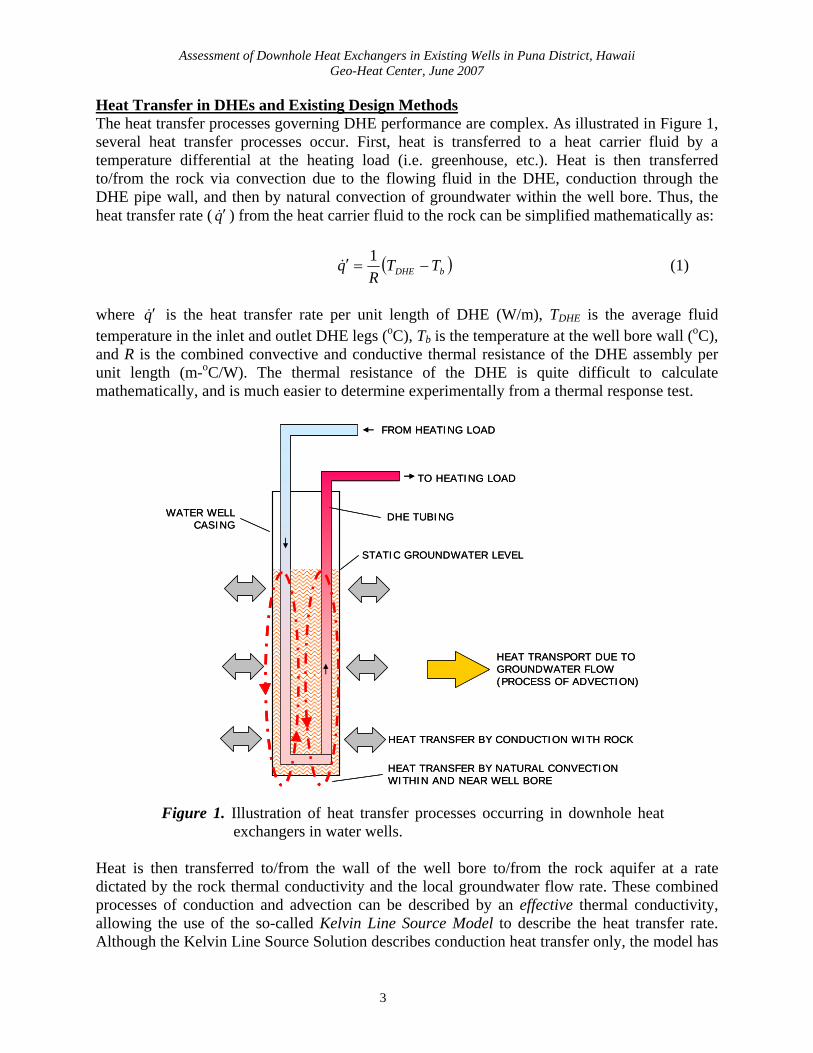
Heat Transfer in DHEs and Existing Design Methods The heat transfer processes governing DHE performance are complex. As illustrated in Figure 1, several heat transfer processes occur. First, heat is transferred to a heat carrier fluid by a temperature differential at the heating load (i.e. greenhouse, etc.). Heat is then transferred to/from the rock via convection due to the flowing fluid in the DHE, conduction through the DHE pipe wall, and then by natural convection of groundwater within the well bore. Thus, the heat transfer rate ( ) from the heat carrier fluid to the rock can be simplified mathematically as: q′&
( bDHE TT )R
q −=′1
& (1)
where is the heat transfer rate per unit length of DHE (W/m), Tq′& DHE is the average fluid temperature in the inlet and outlet DHE legs (oC), Tb is the temperature at the well bore wall (oC), and R is the combined convective and conductive thermal resistance of the DHE assembly per unit length (m-oC/W). The thermal resistance of the DHE is quite difficult to calculate mathematically, and is much easier to determine experimentally from a thermal response test. FROM HEATING LOAD
TO HEATING LOAD
WATER WELLCASING
DHE TUBING
STATIC GROUNDWATER LEVEL
HEAT TRANSPORT DUE TOGROUNDWATER FLOW(PROCESS OF ADVECTION)
HEAT TRANSFER BY CONDUCTION WITH ROCK
HEAT TRANSFER BY NATURAL CONVECTION WITHIN AND NEAR WELL BORE
FROM HEATING LOAD
TO HEATING LOAD
WATER WELLCASING
DHE TUBING
STATIC GROUNDWATER LEVEL
HEAT TRANSPORT DUE TOGROUNDWATER FLOW(PROCESS OF ADVECTION)
HEAT TRANSFER BY CONDUCTION WITH ROCK
HEAT TRANSFER BY NATURAL CONVECTION WITHIN AND NEAR WELL BORE
Figure 1. Illustration of heat transfer processes occurring in downhole heat exchangers in water wells.
Heat is then transferred to/from the wall of the well bore to/from the rock aquifer at a rate dictated by the rock thermal conductivity and the local groundwater flow rate. These combined processes of conduction and advection can be described by an effective thermal conductivity, allowing the use of the so-called Kelvin Line Source Model to describe the heat transfer rate. Although the Kelvin Line Source Solution describes conduction heat transfer only, the model has
3
Assessment of Downhole Heat Exchangers in Existing Wells in Puna District, Hawaii Geo-Heat Center, June 2007
been successfully applied to coupled conduction-convection problems. For example, Deng (2004) used the concept of an effective (or enhanced) thermal conductivity to lump the effects of heat conduction, heat advection due to groundwater flow, and heat transfer due to periodic groundwater extraction from standing column wells. Similarly, Gehlin (2002) describes the use of an effective thermal conductivity to model natural convection of groundwater in and out of groundwater-filled boreholes in granitic rocks with borehole heat exchangers. The Kelvin Line Source Model, described by Lord Kelvin in 1882, is a classic solution used to calculate the temperature distribution around an imaginary vertical line in a semi-infinite solid medium initially at a uniform temperature. The Ingersoll and Plass (1948) adaptation is given as:
∫∞ −′
=Δx
dek
qT ββπ
β
4&
(2)
where ΔT is the temperature change (oC), q′& is the heat transfer rate per length of line source, (W/m), k is the thermal conductivity of the medium [W/(m-oC)], and x is defined as r2/(4αt), where r is the radius from the line source (m), α is the thermal diffusivity of the medium (m2/s), β is an integration variable, and t is the time duration of the heat input (s).
Gehlin and Hellström (2003) cite a method where a simplified solution to Equation 2 is combined with the DHE thermal resistance described by Equation 1. The equation cited by Gehlin and Hellström (2003) allows calculation of the average temperature in a DHE as a function of time and is given by:
( ) Rqtrk
qTtTb
ugDHE ′+⎥⎥⎦
⎤
⎢⎢⎣
⎡−⎟⎟
⎠
⎞⎜⎜⎝
⎛′+= &
&γα
π 2
4ln4
(3)
where TDHE(t) is the average DHE fluid temperature as a function of time (oC), Tug is the undisturbed ground temperature (oC), rb is the well bore radius (m), and γ is the Euler constant equal to 0.5772. All other symbols have been defined previously. It is this equation that will be used to analyze the thermal response test data as described below. DHE TEST METHODS The DHE test methods consisted of three parts: (1) selection of a well for testing, (2) field testing procedures, and (3) data analysis methods. Each is described below. Selection of Well for DHE Testing With assistance from A. Gill of the Department of Business, Economic Development and Tourism (DBEDT) Energy Office, three available wells were identified for possible DHE testing, and Geo-Heat Center staff visited and inspected two of these wells on October 24, 2006. The two wells that were visited are known as the Puna Geothermal Venture (PGV) well MW-2 and the
4
Assessment of Downhole Heat Exchangers in Existing Wells in Puna District, Hawaii Geo-Heat Center, June 2007
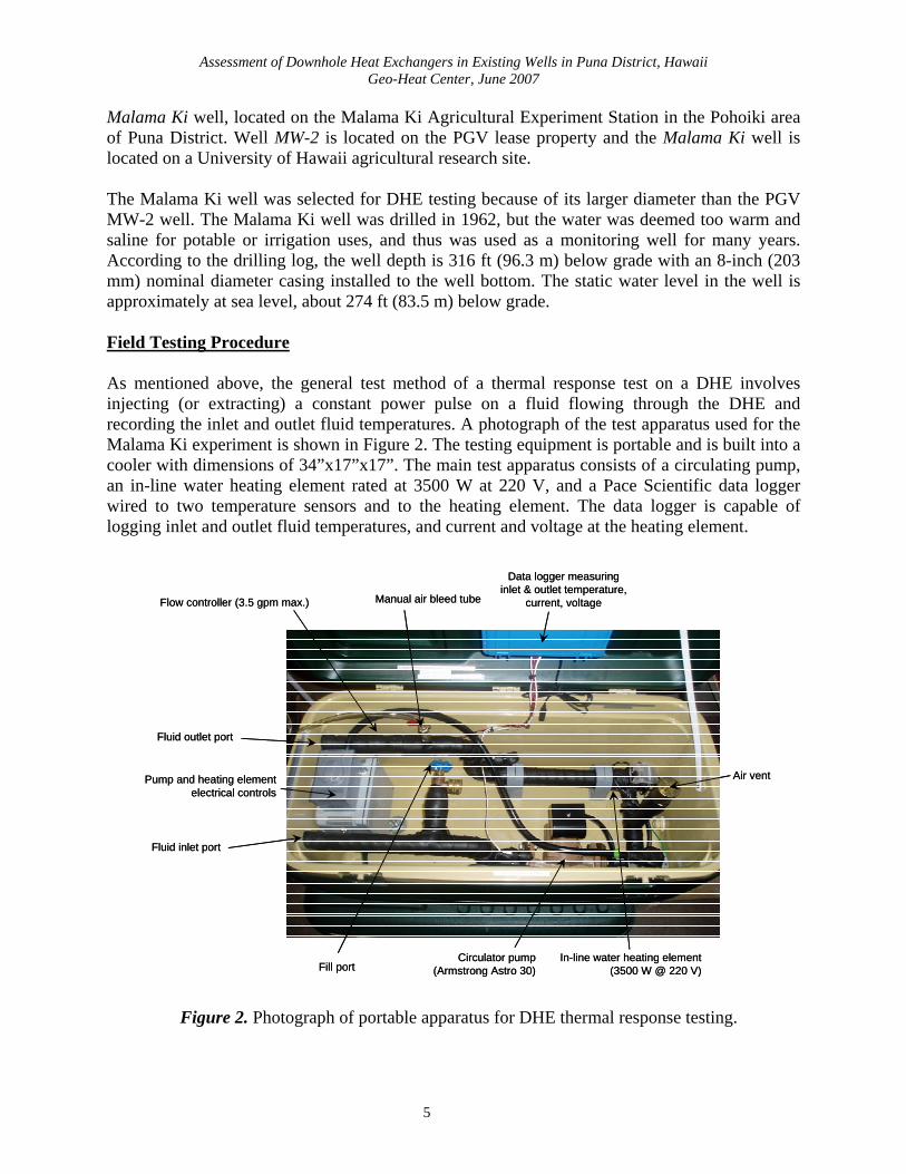
Malama Ki well, located on the Malama Ki Agricultural Experiment Station in the Pohoiki area of Puna District. Well MW-2 is located on the PGV lease property and the Malama Ki well is located on a University of Hawaii agricultural research site. The Malama Ki well was selected for DHE testing because of its larger diameter than the PGV MW-2 well. The Malama Ki well was drilled in 1962, but the water was deemed too warm and saline for potable or irrigation uses, and thus was used as a monitoring well for many years. According to the drilling log, the well depth is 316 ft (96.3 m) below grade with an 8-inch (203 mm) nominal diameter casing installed to the well bottom. The static water level in the well is approximately at sea level, about 274 ft (83.5 m) below grade. Field Testing Procedure As mentioned above, the general test method of a thermal response test on a DHE involves injecting (or extracting) a constant power pulse on a fluid flowing through the DHE and recording the inlet and outlet fluid temperatures. A photograph of the test apparatus used for the Malama Ki experiment is shown in Figure 2. The testing equipment is portable and is built into a cooler with dimensions of 34”x17”x17”. The main test apparatus consists of a circulating pump, an in-line water heating element rated at 3500 W at 220 V, and a Pace Scientific data logger wired to two temperature sensors and to the heating element. The data logger is capable of logging inlet and outlet fluid temperatures, and current and voltage at the heating element.
Fluid inlet port
Manual air bleed tubeFlow controller (3.5 gpm max.)
Circulator pump(Armstrong Astro 30)
Fluid outlet port
Pump and heating elementelectrical controls
In-line water heating element(3500 W @ 220 V)
Air vent
Data logger measuringinlet & outlet temperature,
current, voltage
Fill port
Fluid inlet port
Manual air bleed tubeFlow controller (3.5 gpm max.)
Circulator pump(Armstrong Astro 30)
Fluid outlet port
Pump and heating elementelectrical controls
In-line water heating element(3500 W @ 220 V)
Air vent
Data logger measuringinlet & outlet temperature,
current, voltage
Fill port
Figure 2. Photograph of portable apparatus for DHE thermal response testing.
5
Assessment of Downhole Heat Exchangers in Existing Wells in Puna District, Hawaii Geo-Heat Center, June 2007
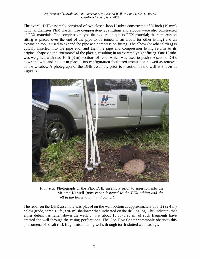
The overall DHE assembly consisted of two closed-loop U-tubes constructed of ¾-inch (19 mm) nominal diameter PEX plastic. The compression-type fittings and elbows were also constructed of PEX materials. The compression-type fittings are unique to PEX material; the compression fitting is placed over the end of the pipe to be joined to an elbow (or other fitting) and an expansion tool is used to expand the pipe and compression fitting. The elbow (or other fitting) is quickly inserted into the pipe end, and then the pipe and compression fitting returns to its original shape via the “memory” of the plastic, resulting in an extremely tight fitting. One U-tube was weighted with two 10-ft (3 m) sections of rebar which was used to push the second DHE down the well and hold it in place. This configuration facilitated installation as well as removal of the U-tubes. A photograph of the DHE assembly prior to insertion in the well is shown in Figure 3.
Figure 3. Photograph of the PEX DHE assembly prior to insertion into the Malama Ki well (note rebar fastened to the PEX tubing and the well in the lower right-hand corner).
The rebar on the DHE assembly was placed on the well bottom at approximately 303 ft (92.4 m) below grade, some 13 ft (3.96 m) shallower than indicated on the drilling log. This indicates that either debris has fallen down the well, or that about 13 ft (3.96 m) of rock fragments have entered the well through the casing perforations. The Geo-Heat Center commonly observes this phenomena of basalt rock fragments entering wells through torch-slotted well casings.
6
Assessment of Downhole Heat Exchangers in Existing Wells in Puna District, Hawaii Geo-Heat Center, June 2007
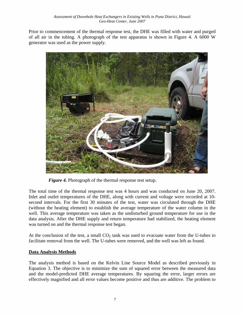
Prior to commencement of the thermal response test, the DHE was filled with water and purged of all air in the tubing. A photograph of the test apparatus is shown in Figure 4. A 6000 W generator was used as the power supply.
Figure 4. Photograph of the thermal response test setup. The total time of the thermal response test was 4 hours and was conducted on June 20, 2007. Inlet and outlet temperatures of the DHE, along with current and voltage were recorded at 10-second intervals. For the first 30 minutes of the test, water was circulated through the DHE (without the heating element) to establish the average temperature of the water column in the well. This average temperature was taken as the undisturbed ground temperature for use in the data analysis. After the DHE supply and return temperature had stabilized, the heating element was turned on and the thermal response test began. At the conclusion of the test, a small CO2 tank was used to evacuate water from the U-tubes to facilitate removal from the well. The U-tubes were removed, and the well was left as found. Data Analysis Methods The analysis method is based on the Kelvin Line Source Model as described previously in Equation 3. The objective is to minimize the sum of squared error between the measured data and the model-predicted DHE average temperatures. By squaring the error, larger errors are effectively magnified and all error values become positive and thus are additive. The problem to
7
Assessment of Downhole Heat Exchangers in Existing Wells in Puna District, Hawaii Geo-Heat Center, June 2007
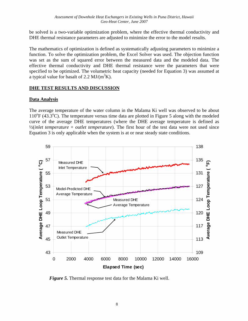
be solved is a two-variable optimization problem, where the effective thermal conductivity and DHE thermal resistance parameters are adjusted to minimize the error to the model results. The mathematics of optimization is defined as systematically adjusting parameters to minimize a function. To solve the optimization problem, the Excel Solver was used. The objection function was set as the sum of squared error between the measured data and the modeled data. The effective thermal conductivity and DHE thermal resistance were the parameters that were specified to be optimized. The volumetric heat capacity (needed for Equation 3) was assumed at a typical value for basalt of 2.2 MJ/(m3K). DHE TEST RESULTS AND DISCUSSION Data Analysis The average temperature of the water column in the Malama Ki well was observed to be about 110oF (43.3oC). The temperature versus time data are plotted in Figure 5 along with the modeled curve of the average DHE temperatures (where the DHE average temperature is defined as ½(inlet temperature + outlet temperature). The first hour of the test data were not used since Equation 3 is only applicable when the system is at or near steady state conditions.
43
45
47
49
51
53
55
57
59
0 2000 4000 6000 8000 10000 12000 14000 16000
Elapsed Time (sec)
Aver
age
DHE
Loop
Tem
pera
ture
(o C)
109
113
117
120
124
127
131
135
138
Aver
age
DHE
Loop
Tem
pera
ture
(o F)Measured DHE
Inlet Temperature
Measured DHEOutlet Temperature
Measured DHEAverage Temperature
Model-Predicted DHEAverage Temperature
Figure 5. Thermal response test data for the Malama Ki well.
8
Assessment of Downhole Heat Exchangers in Existing Wells in Puna District, Hawaii Geo-Heat Center, June 2007
A review of Figure 5 shows a very good fit between the measured and modeled data. The model curve was produced with an optimized effective thermal conductivity value of 11.96 Btu/(hr-ft-oF) (20.68 W/(m-oC)) and a DHE thermal resistance value of 0.0136 hr-ft-oF/Btu (0.007845 m-oC/W). To put these values in perspective, the effective thermal conductivity (including the effects of groundwater flow) is one order of magnitude greater than without groundwater flow. The DHE thermal resistance (including the effects of convection within the well bore) is 40 times greater than for a DHE without well bore convection. Practical Use of the Test Data The main goal of a thermal response test is to obtain data that can be used in DHE design. The primary objective of DHE design is to install adequate length to provide the desired temperature to a heating load. With the effective thermal conductivity and the DHE thermal resistance known from the test, Equation 3 can be re-arranged to solve for the DHE heat extraction rate per unit length (in W/m or Btu/hr/ft) under various design scenarios:
( )
Rtrk
TtTq
b
ugDHE
+⎥⎥⎦
⎤
⎢⎢⎣
⎡−⎟⎟
⎠
⎞⎜⎜⎝
⎛
−=′
γαπ 2
4ln41
& (4)
Note that in Equation 4, is negative for heat extraction. To apply Equation 4 to a hypothetical well with an undisturbed temperature (T
q′&ug) of 140oF (60oC), say, for example, a radiant floor
heating system is under consideration to supply 120oF (48.9oC) to the floor with a design temperature differential across the floor of 10oF (5.5oC). This gives an inlet temperature of 110oF (43.3oC) to the DHE and an outlet temperature of 120oF (48.9oC), for an average DHE temperature of 115oF (46.1oC). Using Equation 4 with the thermal properties determined from the Malama Ki well, the DHE thermal output is estimated at 1328 W/m (1383 Btu/hr/ft). Heat losses for greenhouse bottom heating were estimated by Okahara & Associates, Inc. (2007). The peak heating load was estimated at 25 Btu/hr/ft2 (79 W/m2) of greenhouse area and the average heating load was estimated at about 13.5 Btu/hr/ft2 (42.6 W/m2) of greenhouse area. Thus, for the above DHE example, about 213 ft (65 m) of water column and about 400 ft (122 m) of water column would meet the average heating load and peak heating load, respectively, of a ½-acre greenhouse. PEX DHE Economics For the Malama Ki experiment, the total cost of the installed DHE including shipping and fittings was $1200. However, in a real situation, 1-inch nominal diameter PEX would be used to allow more flow through the system, increasing the DHE cost. Chiasson and Swisher (2007) compared costs of a double U-tube DHE of 1-inch nominal diameter PEX to a single U-tube DHE of 1½-inch nominal diameter black iron. Each of these DHEs has approximately the same flow area, but the black iron DHE costs about 33% more than the PEX DHE. The other advantages of PEX DHEs over metallic DHEs, are that PEX can be transported in rolls
9
Assessment of Downhole Heat Exchangers in Existing Wells in Puna District, Hawaii Geo-Heat Center, June 2007
to the project site with a pickup truck. In addition, PEX DHEs can be installed (and removed) by hand conservatively in less than one working day with two people. Metallic DHEs require a crane truck for installation and removal. CONCLUDING SUMMARY The Geo-Heat Center conducted a thermal response test on a DHE that we installed in an existing well located on the Malama Ki Agricultural Experiment Station in the Pohoiki area of Puna District, Hawaii County, Hawaii. The DHE was fabricated of cross-linked polyethylene (PEX) tubing that was transported and assembled on site. The overall DHE assembly consisted of two closed-loop U-tubes constructed entirely of ¾-inch (19 mm) nominal diameter PEX plastic. The DHE assembly was placed on the well bottom at approximately 303 ft (92.4 m) below grade, some 13 ft (3.96 m) shallower than indicated on the drilling log. This indicates that either debris has fallen down the well, or that about 13 ft (3.96 m) of rock fragments have entered the well through the casing perforations. The thermal response test was conducted with portable apparatus that included a small circulating pump, an in-line water heating element, and a data logger to record inlet and outlet fluid temperatures, and current and voltage at the heating element. Prior to adding heat to the flow stream, the water in the DHE was circulated to establish an average undisturbed groundwater temperature of 110oF (43.3oC). The thermal response test was conducted for 4 hours on June 20, 2007 with data being recorded at 10-second intervals. The test data set was analyzed using a mathematical solution to the so-called Kelvin Line Source model, which describes heat conduction from an imaginary line into a semi-infinite medium. The effective thermal conductivity of the aquifer and the DHE thermal resistance were determined from the solution to an optimization problem, where the error between the measured and modeled data were minimized. The resulting effective thermal conductivity (including the effects of groundwater flow) is one order of magnitude greater than without groundwater flow, and the DHE thermal resistance (including the effects of convection within the well bore) is 40 times greater than for a DHE without well bore convection. To use the thermal response test data in a practical sense, an example is given to demonstrate how the thermal output of a DHE can be calculated. Assuming a 140oF (60oC) well supplies 120oF (48.9oC) water to a radiant floor heating system for greenhouse bottom heating application, it is estimated that about 213 ft (65 m) of water column and about 400 ft (122 m) of water column would meet the average heating load and peak heating load, respectively, of a ½-acre greenhouse. Several advantages of PEX DHEs relative to metallic DHEs have been verified by this project. PEX DHEs are lower in cost and much easier to install than metallic DHEs.
10
Assessment of Downhole Heat Exchangers in Existing Wells in Puna District, Hawaii Geo-Heat Center, June 2007
REFERENCES Chiasson, A.D., G.G. Culver, D. Favata, and S. Keiffer, 2005. “Design, Installation, and
Monitoring of a New Downhole Heat Exchanger”. GRC Transactions, Vol. 29. Chiasson, A.D. and R. Swisher, 2007. “Continuing Advances in PEX Downhole Heat
Exchangers for Direct-Use Heating”. Geo-Heat Center Quarterly Bulletin, Vol. 28, No. 2.
Culver, G., 2005. “A Brief History of DHE Materials”. Geo-Heat Center Quarterly Bulletin,
Vol. 26, No. 1. Deng, Z., 2004. Modeling of Standing Column Wells in Ground Source Heat Pump Applications.
Doctoral Thesis, Oklahoma State University, Stillwater, OK, USA. Gehlin, S., 2002. Thermal Response Test, Method Development and Evaluation. Doctoral Thesis,
Lulea University of Technology, Department of Environmental Engineering, Division of Water Resources Engineering, Lulea, Sweden.
Gehlin, S. and G. Hellström, 2003. “Comparison of Four Models for Thermal Response Test
Evaluation”. American Society of Heating, Refrigerating, and Air-Conditioning Engineers (ASHRAE) Transactions, Vol. 109, Pt. 1.
Ingersoll, L.R. and H.J. Plass, 1948. “Theory of the ground heat pipe heat source for the heat
pump”. Transactions of the American Society of Heating and Ventilating Engineers. Okahara & Associates, Inc., 2007. Feasibility Study on Geothermal Direct Use, Kapoho/Pohoiki
Area. Prepared for County of Hawaii, Department of Research and Development, Hilo, Hawaii, February 2007.
Swisher, R. and G.A. Wright, 1990. “Inhibition of Corrosion at the Air-Water Interface in
Geothermal Downhole Heat Exchangers.” Geo-Heat Center Quarterly Bulletin, Vol. 12, No. 4.
11