Embed Size (px)
Citation preview
Final Draft of the original manuscript: Garcers, G.; Requena, G.; Tolnai, D.; Perez, P.; Adeva, P.; Stark, A.; Schell, N.: Influence of rare-earth addition on the long-period stacking ordered phase in cast Mg–Y–Zn alloys In: Journal of Materials Science (2014) Springer DOI: 10.1007/s10853-013-7967-4
Influence of Rare-earth addition on the Long-Period Stacking Ordered phase in cast Mg-Y-Zn alloys
Gerardo Garcésa,∗, Guillermo Requenab, Domonkos Tolnaic, Pablo Péreza, Paloma
Adevaa, Andreas Starkc, Norbert Schelld. a) DepartmentofPhysical Metallurgy, NationalCenter for Metallurgical Research
(CENIM-CSIC), Avda. Gregorio del Amo 8, 28040 Madrid, Spain b) Institute of Materials Science and Technology,ViennaUniversity of Technology,
Karlsplatz 13/308, A-1040 Vienna, Austria c) Institute of Materials Research, Helmholtz-ZentrumGeesthacht, Max-Planck-
Str. 1, 21502 Geesthacht, Germany d) Structural Research on New Materials, Helmholtz-ZentrumGeesthacht
Outstation at DESY in Hamburg, Germany
Abstract
The microstructure and thermal stability of the Mg97Y2Zn1(at.%) alloy, modified with
the addition of 0.5 at.% of gadolinium or neodymium, have been examined by
synchrotron radiation diffraction during in-situ differential scanning calorimetry. The
microstructure of the three alloys consists of magnesium dendrites with the Long Period
Stacking Ordered (LPSO) phase at interdendritic regions. Rare-earth atoms substitute
yttrium atoms in the LPSO phase, promoting the formation of the 14H structure. Lattice
parameters of the LPSO do not change significantly with the rare earth addition.
However, they reduce the melting point of the LPSOphase, especially in the case of
neodymium addition.
Keywords: Magnesium alloys; LPSO; Synchrotron diffraction.
∗corresponding author: Tel.: +34915538900; fax: +34-915347425 E-mail address: [email protected] (Gerardo Garcés)
1
1. Introduction
Magnesium alloys combining yttrium/rare earth (Y, Gd, Nd, Dy, etc) elements and
transition metals (Zn, Cu, Ni) are effectively strengthened by the presence of Long
Period Stacking Ordered (LPSO) structures [1-8]. They can combine high strength with
acceptable ductility and enhanced creep resistance. LPSO-phases are solid solutions of
yttrium or rare-earthelements and transition metals in the magnesium lattice, where
these atoms are arranged periodically in the magnesium basal planes forming ordered
structures [9-12]. Different LPSO crystal structures have been reported, i.e., 6H, 10H,
14H, 18R and 24R [13-15] depending on the thermal history of the material. The 18R
structure is observed mainly in the as-cast condition. However, this structure is not
stable at high temperature and is gradually replaced by a 14 H structure[11]. Recently,
Egusa and Abe[12] have proposed crystal/order structural models for 18R and 14H
phases formed in Mg–Zn–RE alloys. These phases can be rationalized by space
groupsC2/m, P3112 or P3212 for the 18R type and P63/mcm for the 14H type. The
characteristic ordered features are well represented by local Zn6RE8 clusters, which
are embedded in the fcc stacking layers in accordance with the L12 type short-range
order.
A Mg97Y2Zn1(at.%) alloy produced by warm extrusion of rapid solidified ribbons
exhibited high yield strength, about 610 MPa, with 5% of elongation at room
temperature[1]. Recently, Yamasaki et al.[4] have developed extruded
Mg97Y2Zn1(at.%) alloys that combine high yield stress (around 350 MPa) and
acceptable ductility (around 8%) by controlling the cooling rate during the casting
process and the extrusion parameters.
Optimization of the microstructure by developing fine lamella inside the magnesium
grains can be achieved through an appropriate thermal treatment, resulting in additional
2
strengthening[8,16,17]. At room temperature, the hardening induced by these long
plates is small. This fact is attributed to the crystallographic orientation of the
precipitates within the magnesium matrix. Since they are located in basal planes, they
have a low hardening effect on the basal slip system[18]. However, at high temperature,
where non-basal slip systems are active, the lamellar structure increases the creep
resistance of these alloys [8]. In a recent review about precipitation and hardening in
magnesium alloys[19], Nie concluded that precipitate plates formed on prismatic
planes provide the most effective barrier to gliding dislocations and propagating twins
in the magnesium matrix. The formation of this kind of precipitates has been reported in
Mg-Y-RE systems, such a Mg-Y-Nd, Mg-Gd, Mg-Gd-Nd, etc. Moreover, Nie suggested
that a higher strength can be achieved if a high density of strong plate-shaped
precipitates with prismatic and basal habit planes and with a high aspect ratio can be
introduced. Recently, it has been reported that the addition of rare-earth elements to the
Mg-Y-Zn system containing LPSO phases promote the formation of plates in the
prismatic and basal planes, preserving the LPSO phase in some conditions, and
considerably increasing the strength of Mg-Y-RE-Zn(RE=Gd and Nd) alloys at room
temperature[20-22].
The presence of additional elements can modify the crystallography and thermal
stability of the LPSO phase. Therefore, this paper explores the influence of the
additionof 0.5 at.% of Gd and 0.5 at.% of Nd to the Mg97Y2Zn1(at.%) alloy.
2. Experimental procedure
Three alloyswith nominal compositions Mg97Y2Zn1(at.%), Mg96.5Y2Zn1Gd0.5(at.%)
and Mg96.5Y2Zn1Nd0.5(at.%) were prepared by melting high purity elements Mg and Zn
and Mg-22%Y(wt.%), Mg-20%Gd(wt.%) and Mg-22%Nd (wt.%) master alloys in an
3
electric resistance furnace. The three alloys were cast in a 12 mm diameter cylindrical
steel mould. For comparative purposes, a fully LPSO alloy with composition
Mg88Y8Zn4(at.%) was also prepared in an induction melting furnace using a graphite
tube coated with boron nitride in argon atmosphere. The fully LPSO alloy was
homogenized at 350 ºC for 24 hours.
Microstructural characterization of the alloys was carried out by optical (OM), scanning
(SEM) and transmission electron microscopy (TEM). Specimens for TEM observation
were prepared by electrolytic polishing using a reactive mixture of 25% nitric acid and
75 % methanol at -20ºC and 20V. Then, ion milling at liquid nitrogen temperature was
used to remove the fine oxide film formed on the surface during electrolytic polishing.
The thermal stability of the three alloys was monitored by DSC experiments using
heating/cooling rates of 10 Kmin-1 under argon atmosphere in a Mettler Toledo 822
DSC equipment. The samples were subjected to one DSC heating/cooling cycle
between RT and 570 °C.
Synchrotron radiation diffraction was performed at the P07 – HEMS beamline of
PETRA III, at the DeutschesElektronen-Synchrotron (DESY) during in-situ DSC
experiments. The samples were encapsulated in stainless steel crucibles during the
measurement, using an empty crucible as reference. The DSC unit was placed inside the
coil of a Bähr 805A/D dilatometer. The dilatometer and the DSC unit are modified for
synchrotron experiments. Two Kapton windows on the sides of the chamber and a hole
in the DSC pan allow the high energy X-ray beam to reach the sample and the detector
without disturbance. The measurements were performed in argon flow. The diffraction
patterns were recorded using an exposure time of 1 s by a Perkin-Elmer XRD 1622
flatpanel detector with an array of 20482pixel, with an effective pixel size of 200×200
µm2. The beam energy was 100 keV, corresponding to a wavelength of 0.0124 nm.
4
LaB6 was used as a reference to calibrate the acquired diffraction spectra. The detector-
to-sample distance was 1918.95 mm. Conventional line profiles were obtained by
azimuthal integration of the Debye-Scherrer rings. The heating/cooling rate of the DSC
was 40 Kmin-1 and 10 Kmin-1 below and above 400 ºC, respectively. Similarly to the
laboratory DSC scans, the samples were subjected to one DSC cycle between RT and
560 °C.
3. Results and Discussion
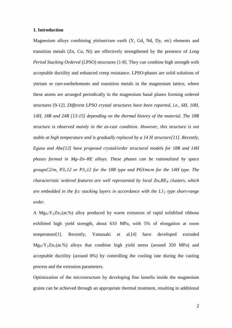
Figure 1(a-c) shows the microstructure of the MgY2Zn1(RE0.5) alloys in the as-cast
condition. The microstructure consists of magnesium dendrites with the LPSO phase
distributed at interdendritic regions. The volume fraction of LPSO phase is similar for
the three alloys, about 22 vol.%. The Mg88Y8Zn4(at.%) alloy consists of long LPSO
laths with a small volume fraction of magnesium islands (Figure 1d).
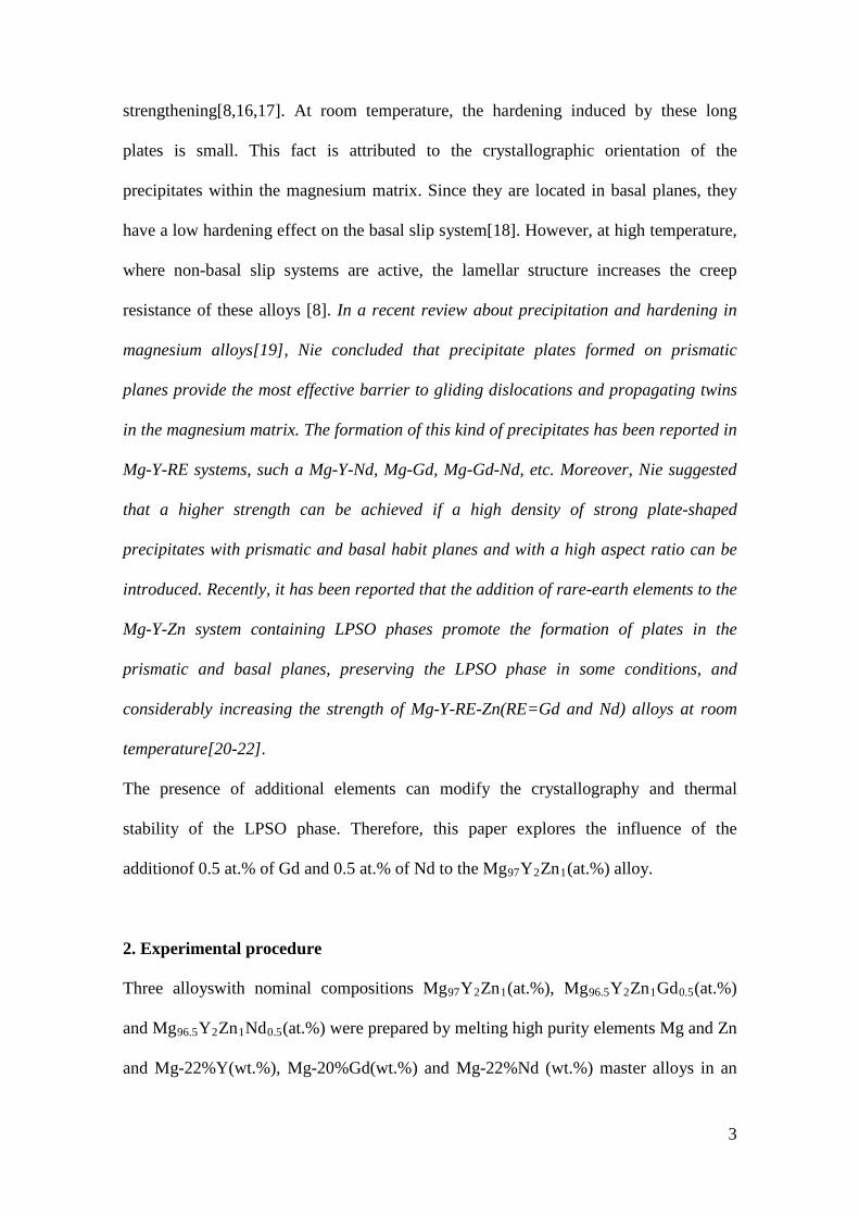
Figure 2 (a-h) shows the Debye-Scherrer rings obtained at RT for the alloys in the as-
cast condition. It is interesting to note that diffuse scattering (streaking) is observed in
the case of the LPSO phase in the MgY2Zn1(RE0.5) alloys. This is especially marked for
the smaller diffraction ring that correspondsto (0003) reflex of the 18R LPSO phase.
Okuda et al.[23], using SAXS, reported diffuse streaks connecting diffracted spots
suggesting that 18R and 10H structures coexist in a coherent way in the same grains.
However, in this case, these diffuse streaks are not observed connecting reflexes from
other LPSO structures. On the other hand, similar diffuse streaking has been observed in
diffraction patternsby TEM. Li et al.[24] showed diffuse streaking in the [0001]
direction due to the formation of stacking faults (SFs)in the (0001) basal plane of
deformed pure magnesium. Garces et al.[8] also observed diffuse streaking along the
[0002] direction in the magnesium grains of MgY2Zn1 alloys heat treated at high
5
temperature. This diffuse streaking was related tostacking faults in the basal plane due
to the formation of long LPSO precipitates having the 14H structure. The fact that the
streaking is radial to the diffraction ring indicates that the SFs are located parallel to the
(0003) planes, namely in the c direction of the 18R LPSO lattice.
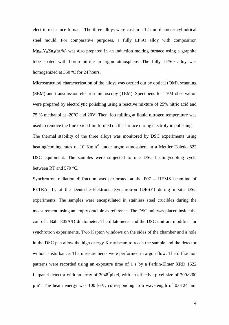
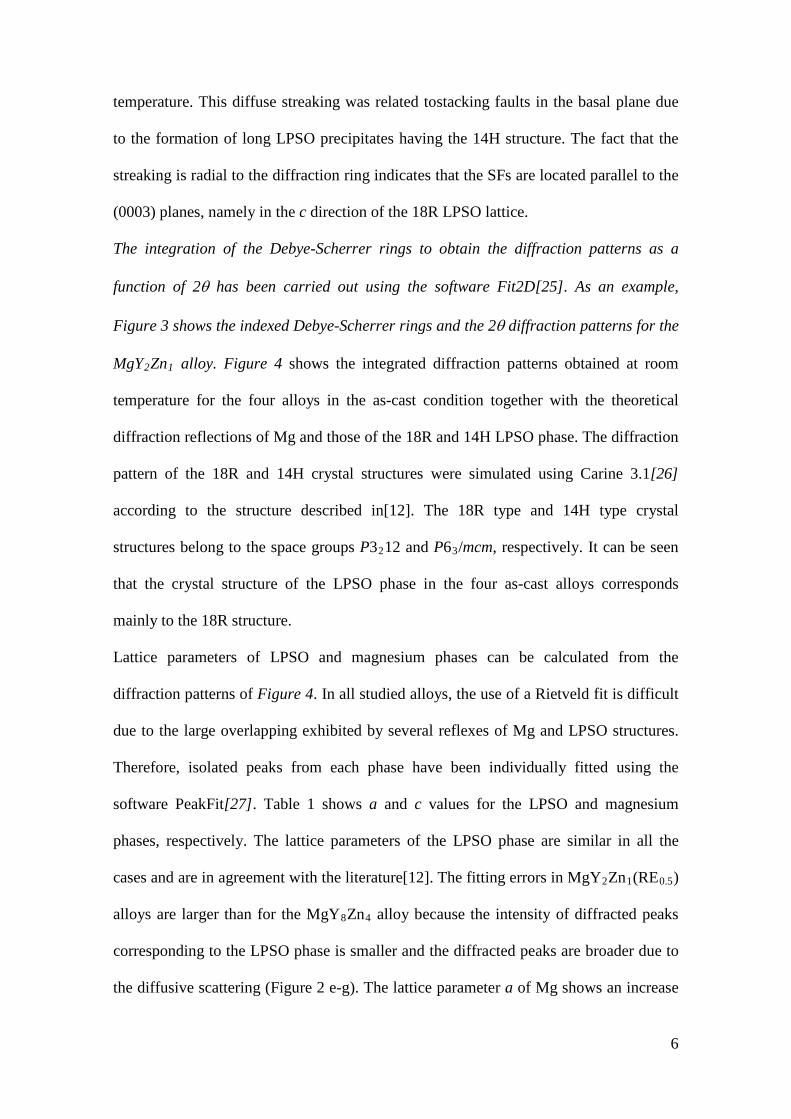
The integration of the Debye-Scherrer rings to obtain the diffraction patterns as a
function of 2θ has been carried out using the software Fit2D[25]. As an example,
Figure 3 shows the indexed Debye-Scherrer rings and the 2θ diffraction patterns for the
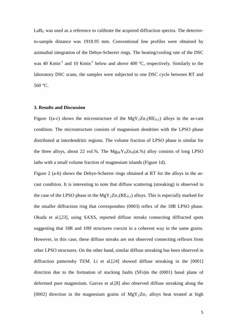
MgY2Zn1 alloy. Figure 4 shows the integrated diffraction patterns obtained at room
temperature for the four alloys in the as-cast condition together with the theoretical
diffraction reflections of Mg and those of the 18R and 14H LPSO phase. The diffraction
pattern of the 18R and 14H crystal structures were simulated using Carine 3.1[26]
according to the structure described in[12]. The 18R type and 14H type crystal
structures belong to the space groups P3212 and P63/mcm, respectively. It can be seen
that the crystal structure of the LPSO phase in the four as-cast alloys corresponds
mainly to the 18R structure.
Lattice parameters of LPSO and magnesium phases can be calculated from the
diffraction patterns of Figure 4. In all studied alloys, the use of a Rietveld fit is difficult
due to the large overlapping exhibited by several reflexes of Mg and LPSO structures.
Therefore, isolated peaks from each phase have been individually fitted using the
software PeakFit[27]. Table 1 shows a and c values for the LPSO and magnesium
phases, respectively. The lattice parameters of the LPSO phase are similar in all the
cases and are in agreement with the literature[12]. The fitting errors in MgY2Zn1(RE0.5)
alloys are larger than for the MgY8Zn4 alloy because the intensity of diffracted peaks
corresponding to the LPSO phase is smaller and the diffracted peaks are broader due to
the diffusive scattering (Figure 2 e-g). The lattice parameter a of Mg shows an increase
6
with respect to pure Mg (a = 0.32089 nm and c = 0.52101 nm[28]). The magnesium
phase in the MgY2Zn1(RE0.5) alloys contains a small amount of yttrium in solid
solution which is reported to increase a, i.e. reducing the c/a ratio[29,30].
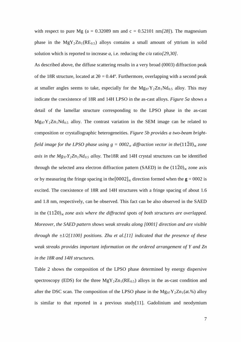
As described above, the diffuse scattering results in a very broad (0003) diffraction peak
of the 18R structure, located at 2θ = 0.44º. Furthermore, overlapping with a second peak
at smaller angles seems to take, especially for the Mg97Y2Zn1Nd0.5 alloy. This may
indicate the coexistence of 18R and 14H LPSO in the as-cast alloys. Figure 5a shows a
detail of the lamellar structure corresponding to the LPSO phase in the as-cast
Mg97Y2Zn1Nd0.5 alloy. The contrast variation in the SEM image can be related to
composition or crystallographic heterogeneities. Figure 5b provides a two-beam bright-
field image for the LPSO phase using g = 0002α diffraction vector in the⟨112�0⟩∝ zone
axis in the Mg97Y2Zn1Nd0.5 alloy. The18R and 14H crystal structures can be identified
through the selected area electron diffraction pattern (SAED) in the ⟨112�0⟩∝ zone axis
or by measuring the fringe spacing in the[0002]∝ direction formed when the g = 0002 is
excited. The coexistence of 18R and 14H structures with a fringe spacing of about 1.6
and 1.8 nm, respectively, can be observed. This fact can be also observed in the SAED
in the ⟨112�0⟩∝ zone axis where the diffracted spots of both structures are overlapped.
Moreover, the SAED pattern shows weak streaks along [0001] direction and are visible
through the ±1/2{1100} positions. Zhu et al.[11] indicated that the presence of these
weak streaks provides important information on the ordered arrangement of Y and Zn
in the 18R and 14H structures.
Table 2 shows the composition of the LPSO phase determined by energy dispersive
spectroscopy (EDS) for the three MgY2Zn1(RE0.5) alloys in the as-cast condition and
after the DSC scan. The composition of the LPSO phase in the Mg97Y2Zn1(at.%) alloy
is similar to that reported in a previous study[11]. Gadolinium and neodymium
7
additions have two different effects on LPSO phase composition. On one hand, zinc
content slightly decreases with respect to LPSO formed in the Mg97Y2Zn1 alloy. On the
other hand, yttrium content decreases up to approximately 5 at.%, while the rare-earth
content is around 1.5 at.% in both alloys in as-cast condition. The sum of yttrium and
rare earth concentration in quaternary alloys is equal to the yttrium content in the
ternary alloy, indicating that rare-earth atoms substitute yttrium atoms in the LPSO
structure. Thus, an increase in the volume fraction of the LPSO phase in the
Mg97Y2Zn1Gd0.5 and Mg97Y2Zn1Nd0.5 alloys may be expected due to the excess of
yttrium. However, the volume fraction of the LPSO phase is similar in the three alloys
(about 22 vol%) suggesting that the maximum volume fraction of the LPSO phase in
the alloys is fixed by the zinc content. Therefore, the excess of yttrium and rare earth
elements could favour the formation of new phases.
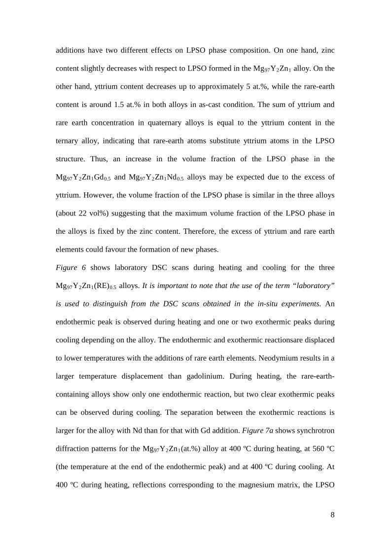
Figure 6 shows laboratory DSC scans during heating and cooling for the three
Mg97Y2Zn1(RE)0.5 alloys. It is important to note that the use of the term “laboratory”
is used to distinguish from the DSC scans obtained in the in-situ experiments. An
endothermic peak is observed during heating and one or two exothermic peaks during
cooling depending on the alloy. The endothermic and exothermic reactionsare displaced
to lower temperatures with the additions of rare earth elements. Neodymium results in a
larger temperature displacement than gadolinium. During heating, the rare-earth-
containing alloys show only one endothermic reaction, but two clear exothermic peaks
can be observed during cooling. The separation between the exothermic reactions is
larger for the alloy with Nd than for that with Gd addition. Figure 7a shows synchrotron
diffraction patterns for the Mg97Y2Zn1(at.%) alloy at 400 ºC during heating, at 560 ºC
(the temperature at the end of the endothermic peak) and at 400 ºC during cooling. At
400 ºC during heating, reflections corresponding to the magnesium matrix, the LPSO
8
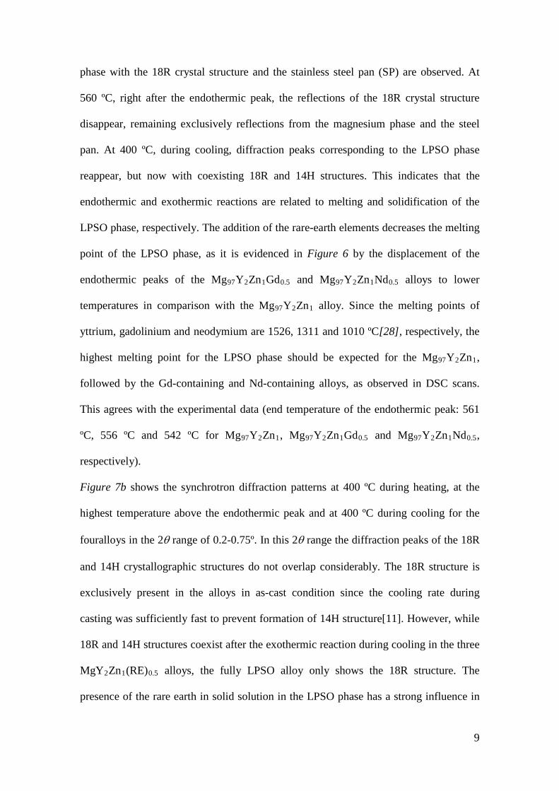
phase with the 18R crystal structure and the stainless steel pan (SP) are observed. At
560 ºC, right after the endothermic peak, the reflections of the 18R crystal structure
disappear, remaining exclusively reflections from the magnesium phase and the steel
pan. At 400 ºC, during cooling, diffraction peaks corresponding to the LPSO phase
reappear, but now with coexisting 18R and 14H structures. This indicates that the
endothermic and exothermic reactions are related to melting and solidification of the
LPSO phase, respectively. The addition of the rare-earth elements decreases the melting
point of the LPSO phase, as it is evidenced in Figure 6 by the displacement of the
endothermic peaks of the Mg97Y2Zn1Gd0.5 and Mg97Y2Zn1Nd0.5 alloys to lower
temperatures in comparison with the Mg97Y2Zn1 alloy. Since the melting points of
yttrium, gadolinium and neodymium are 1526, 1311 and 1010 ºC[28], respectively, the
highest melting point for the LPSO phase should be expected for the Mg97Y2Zn1,
followed by the Gd-containing and Nd-containing alloys, as observed in DSC scans.
This agrees with the experimental data (end temperature of the endothermic peak: 561
ºC, 556 ºC and 542 ºC for Mg97Y2Zn1, Mg97Y2Zn1Gd0.5 and Mg97Y2Zn1Nd0.5,
respectively).
Figure 7b shows the synchrotron diffraction patterns at 400 ºC during heating, at the
highest temperature above the endothermic peak and at 400 ºC during cooling for the
fouralloys in the 2θ range of 0.2-0.75º. In this 2θ range the diffraction peaks of the 18R
and 14H crystallographic structures do not overlap considerably. The 18R structure is
exclusively present in the alloys in as-cast condition since the cooling rate during
casting was sufficiently fast to prevent formation of 14H structure[11]. However, while
18R and 14H structures coexist after the exothermic reaction during cooling in the three
MgY2Zn1(RE)0.5 alloys, the fully LPSO alloy only shows the 18R structure. The
presence of the rare earth in solid solution in the LPSO phase has a strong influence in
9
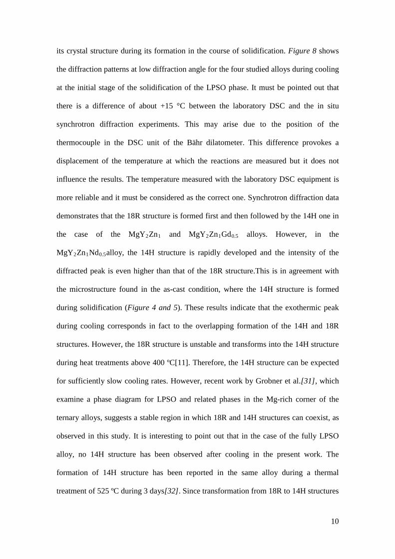
its crystal structure during its formation in the course of solidification. Figure 8 shows
the diffraction patterns at low diffraction angle for the four studied alloys during cooling
at the initial stage of the solidification of the LPSO phase. It must be pointed out that
there is a difference of about +15 °C between the laboratory DSC and the in situ
synchrotron diffraction experiments. This may arise due to the position of the
thermocouple in the DSC unit of the Bähr dilatometer. This difference provokes a
displacement of the temperature at which the reactions are measured but it does not
influence the results. The temperature measured with the laboratory DSC equipment is
more reliable and it must be considered as the correct one. Synchrotron diffraction data
demonstrates that the 18R structure is formed first and then followed by the 14H one in
the case of the MgY2Zn1 and MgY2Zn1Gd0.5 alloys. However, in the
MgY2Zn1Nd0.5alloy, the 14H structure is rapidly developed and the intensity of the
diffracted peak is even higher than that of the 18R structure.This is in agreement with
the microstructure found in the as-cast condition, where the 14H structure is formed
during solidification (Figure 4 and 5). These results indicate that the exothermic peak
during cooling corresponds in fact to the overlapping formation of the 14H and 18R
structures. However, the 18R structure is unstable and transforms into the 14H structure
during heat treatments above 400 ºC[11]. Therefore, the 14H structure can be expected
for sufficiently slow cooling rates. However, recent work by Grobner et al.[31], which
examine a phase diagram for LPSO and related phases in the Mg-rich corner of the
ternary alloys, suggests a stable region in which 18R and 14H structures can coexist, as
observed in this study. It is interesting to point out that in the case of the fully LPSO
alloy, no 14H structure has been observed after cooling in the present work. The
formation of 14H structure has been reported in the same alloy during a thermal
treatment of 525 ºC during 3 days[32]. Since transformation from 18R to 14H structures
10
is slow, it is expected that lower cooling rates are required to observe the appearance of
the diffracted peaks corresponding to the 14H structure in the fully LPSO alloy.
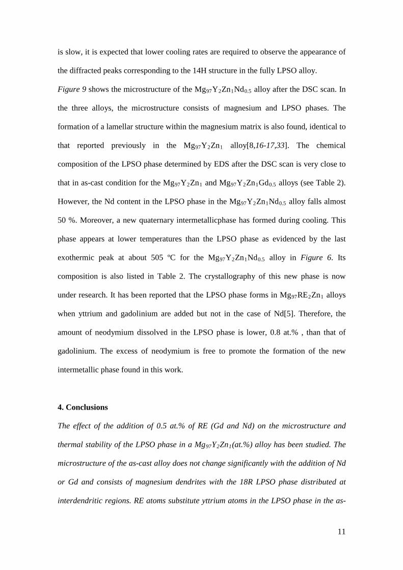
Figure 9 shows the microstructure of the Mg97Y2Zn1Nd0.5 alloy after the DSC scan. In
the three alloys, the microstructure consists of magnesium and LPSO phases. The
formation of a lamellar structure within the magnesium matrix is also found, identical to
that reported previously in the Mg97Y2Zn1 alloy[8,16-17,33]. The chemical
composition of the LPSO phase determined by EDS after the DSC scan is very close to
that in as-cast condition for the Mg97Y2Zn1 and Mg97Y2Zn1Gd0.5 alloys (see Table 2).
However, the Nd content in the LPSO phase in the Mg97Y2Zn1Nd0.5 alloy falls almost
50 %. Moreover, a new quaternary intermetallicphase has formed during cooling. This
phase appears at lower temperatures than the LPSO phase as evidenced by the last
exothermic peak at about 505 ºC for the Mg97Y2Zn1Nd0.5 alloy in Figure 6. Its
composition is also listed in Table 2. The crystallography of this new phase is now
under research. It has been reported that the LPSO phase forms in Mg97RE2Zn1 alloys
when yttrium and gadolinium are added but not in the case of Nd[5]. Therefore, the
amount of neodymium dissolved in the LPSO phase is lower, 0.8 at.% , than that of
gadolinium. The excess of neodymium is free to promote the formation of the new
intermetallic phase found in this work.
4. Conclusions
The effect of the addition of 0.5 at.% of RE (Gd and Nd) on the microstructure and
thermal stability of the LPSO phase in a Mg97Y2Zn1(at.%) alloy has been studied. The
microstructure of the as-cast alloy does not change significantly with the addition of Nd
or Gd and consists of magnesium dendrites with the 18R LPSO phase distributed at
interdendritic regions. RE atoms substitute yttrium atoms in the LPSO phase in the as-
11
cast condition and modified the crystallography of the LPSO phase, especially in the
case of the addition of Nd which promotes the formation the 14H structure. Moreover,
in this alloy, the LPSO phase is not stable and a new intermetallic phase is formed after
the 14H and 18R LPSO phases during cooling from 570 °C at 10 Kmin-1.RE addition
decreases the melting point of the LPSO phase. The lower the melting point of the RE
the lower the melting point of the LPSO phase.
Acknowledgements
The authors are grateful to MEC for financial support for this work under project
MAT2009-07811. The DeutchesElektronen-Synchrotron DESY is acknowledged for
the provision of beamtime at the P07 beamline of the Petra III synchrotron facilityin the
framework of proposal I-20120285 EC.The authors would like to thank Dr. A. Rhys
Williams for proof-reading the manuscript.
5. References
[1] Inoue A, Kawamura Y, Matsushita M, Hayashi K, Koike J (2001) Novel hexagonal
structure and ultrahigh strength of magnesium solid solution in the Mg–Zn–Y system,
J Mater Res 16:1894-1900.
[2] Kawamura Y, Kasahara T, Izumi S, Yamasaki M (2006) Elevated Temperature
Mg97Y2Cu1 Alloy with Long Period Ordered Structure, ScrMater 55:453-456
[3] Hagihara K, Kinoshita A, Sugino Y, Yamasaki M, Kawamura Y, Yasuda HY,
UmakoshiY (2010) Effect of long-period stacking ordered phase on mechanical
properties of Mg97Zn1Y2 extruded alloy, Acta Mater58:6282-6293
[4] Yamasaki M, Hashimoto K, Hagihara K, Kawamura Y (2011) Effect of
Multimodal Microstructure Evolution on Mechanical Properties of Mg-Zn-Y
Extruded Alloy, Acta Mater 59:3646-3658.
12
[5] Kawamura Y, Yamasaki M (2007)Formation and Mechanical Properties of
Mg97Zn1RE2 Alloys with Long Period Stacking Ordered Structure, MatTrans
48:2986-2992
[6] Garces G, Pérez P, Gonzalez S, Adeva P(2006) Development of Long-Period
ordered structures during crystallization of amorphous Mg80TM10Y10, Int J Mater
Res 4:404-408
[7] Mi SB, Jin QQ (2013) New polytypes of long-period stacking ordered structures
in Mg–Co–Y, Scripta Mater 68:635-638
[8] GarcesG, Oñorbe E, DobesF, PérezP, Antoranz JM, AdevaP (2012) Effect of
microstructure on creep behaviour of cast Mg97Y2Zn1 (at.%) alloy, MaterSci Eng
A 539:48-55
[9] Luo ZP, Zhang SQ (2000) High-resolution electron microscopy on the X-Mg12ZnY
phase in a high strength Mg-Zn-Zr-Y magnesium alloy, J Mater SciLetter 19:813-816
[10] Abe E,Kawamura Y, Hayashi K, Inoue A (2002)Long-period ordered structure in
a high-strength nanocrystalline Mg-1 at% Zn-2 at% Y alloy studied by atomic-
resolution Z-contrast STEM , Acta Mater50:3845-3857
[11] Zhu YM, Morton AJ, Nie JF (2010) The 18R and 14H long-period stacking ordered
structures in Mg–Y–Zn alloys,Acta Mater 58:2936-2947
[12] Egusa D. Abe E (2012) The structure of long period stacking/order Mg–Zn–RE
phases with extended non-stoichiometry ranges,Acta Mater 60:166-178
[13] Chino Y, Mabuchi M, Hagiwara S, Iwasaki H, Yamamoto A, Tsubakino H (2004)
Novel equilibrium two phase Mg alloy with long-period ordered structure Scr
Mater 51:771-714
13
[14] Matsuda M, Ii S, Kawamura Y, Ikuhara Y, Nishida M (2005) Variation of long-
period stacking order structures in rapidly solidified Mg97Zn1Y2 alloy Mater Sci
Eng A 393:269-274.
[15] Abe E, Ono A, Itoi T, Yamasaki M, Kawamura Y (2011) Polytypes of long-period
stacking structures synchronized with chemical order in a dilute Mg-Zn-Y alloy
Phil Mag. Letters 91:690-696
[16] Nie JF, Oh-ishi K, Gao X, Hono K(2008) Solute segregation and precipitation in a
creep-resistant Mg–Gd–Zn alloy,Acta Mater 56:6061-6076
[17] Yamasaki M, Sasaki M, Nishijima M, Hiraga K, Kawamura Y (2007)Formation
of 14H long period stacking ordered structure and profuse stacking faults in Mg-
Zn-Gd alloys during isothermal aging at high temperature, Acta Mater 55:6798-
680
[18] GengJ, ChunYB, StanfordN, DaviesCHJ, NieJF, BarnettMR(2011) Processing and
properties of Mg–6Gd–1Zn–0.6Zr: Part 2. Mechanical properties and particle twin
interactions, Mat Sci Eng A 528A:3659-3665
[19] Nie JF (2012) Precipitation and Hardening in Magnesium Alloys Met Mater
Trans A 43:3891-3939
[20] Honma T, Ohkubo T, Kamado S,Hono K (2007) Effect of Zn additions on the
age-hardening of Mg–2.0Gd–1.2Y–0.2Zr alloys,Acta Mater 55:4137-4150
[21] YinDD, WangQD, GaoY, ChenCJ, Zheng J(2011) Effects of heat treatments on
microstructure and mechanical properties of Mg–11Y–5Gd–2Zn–0.5Zr (wt.%),J
Alloys Comp 509:1696-1704
[22] LeeJB, K Sato, TJ Konno, Hiraga K (2011)Complex precipitates with long
periodic stacking (LPS) phase and precipitation behaviors in the
Mg97Zn1Y1.5Nd0.5 alloy by age-annealing , Intermetallics 19:1096-1101
14
[23] Okuda H, Horiuchi T, Tsukamoto T, Ochiai S, Yamasaki M, Kawamura Y(2013)
Evolution of long-period stacking ordered structures on annealing as-cast
Mg85Y9Zn6 alloy ingot observed by synchrotron radiation small-angle scattering,
ScrMater 68:575-578.
[24] Li B, Yan PF, Sui ML, Ma E (2010) Transmission electron microscopy study of
stacking faults and their interaction with pyramidal dislocations in deformed
Mg,Acta Mater 58:173-179
[25] Hammersley AP, SvenssonSO, Hanfland M, Fitch AN, Häusermann D (1996)
Two-Dimensional Detector Software: From Real Detector to Idealised Image or
Two-Theta Scan, High Pressure Research14:235-248
[26] http://carine.crystallography.pagespro-orange.fr/
[27] http://www.sigmaplot.com/products/peakfit/peakfit.php
[28] VillarsP, CalvertLD (1985) Pearson´s Handbook of Crystallographic data for
intermetallic Phases. American Society for Metals, Metal Park, Ohio 2690
[29] SugamataM, HanawaS, Kaneko J (1997) Structures and mechanical properties of
rapidly solidified Mg-Y based alloys, Mater SciEng A 226-228:861-866
[30] AgnewSR, YooMH, Tome CN(2001) Application of texture simulation to
understanding mechanical behavior of Mg and solid solution alloys containing Li
or Y, Acta Mater49 :4277-4289
[31] Grobner J, Kozlov A, Fang XY, Geng J, Nie JF, Schimdt-Fetzer R (2012)Phase
equilibria and transformations in ternary Mg-rich Mg–Y–Zn alloys, Acta Mater
60:5948-5962
[32] Hagihara K, Sugino Y, Fukusumi Y, Umakoshi Y, Nakano T (2011)Plastic
Deformation Behavior of Mg12ZnY LPSO-Phase with 14H-Typed Structure,
Mater Trans52:1096-1103
15

[33] Oñorbe E, Garces G, Perez P, Adeva P (2012) Effect of the LPSO volume fraction
on the microstructure and mechanical properties of Mg-Y2x-Znx alloys, J Mater
Sci 47:1085-1093
16
Figure captions
Figure1. Microstructure ofthe alloys in the as-cast condition. (a) Mg97Y2Zn1 alloy (OM),
(b) Mg97Y2Zn1Gd0.5 alloy (OM), (c) Mg97Y2Zn1Nd0.5 alloy (OM) and (d)
Mg88Y8Zn4alloy (SEM).
Figure 2(a-h) Synchrotron diffraction patterns obtained from the 2D detector. (a)
Mg97Y2Zn1,(b) Mg97Y2Zn1Gd0.5, (c) Mg97Y2Zn1Nd0.5and (d) Mg88Y8Zn4 alloys in
as-cast condition. (e-h) Detail of the inner ring, which corresponds to the (0003) plane
of the LPSO phase.
Figure 3(a-b) Synchrotron diffraction patterns (a) obtained from the 2D detector and
(b) as a function of 2θ corresponding to the Mg97Y2Zn1.
Figure 4. Synchrotron diffraction patterns as a function of 2θ corresponding to the
Mg97Y2Zn1, Mg97Y2Zn1Gd0.5, Mg97Y2Zn1Nd0.5 and Mg88Y8Zn4 alloys. The
diffraction patterns of the 18R, 14H and Mg crystal structures were simulated using
Carine 3.1. SP designates diffraction reflexes of the stainless steel pan.
Figure 5. (a) Secondary electron image of the microstructure of the as-cast
Mg97Y2Zn1Nd0.5 alloy. (b) Bright field TEM image of the LPSO phase in the as-cast
Mg97Y2Zn1Nd0.5alloy (B= 1120 and g=(0002)). (c) Selected area diffraction pattern
of the Mg97Y2Zn1Nd0.5 alloy in the 1120 zone axis.
Figure 6. Laboratory DSC scans (heating and cooling) recorded at 10 Kmin-1 for the
Mg97Y2Zn1, Mg97Y2Zn1Gd0.5 and Mg97Y2Zn1Nd0.5 alloys.
Figure 7(a,b).(a) Synchrotron diffraction patterns at 400 and 560 ºC during heating and
at 400 ºC during coolingfor the Mg97Y2Zn1 alloy. (b) Synchrotron diffraction patterns
at 400 ºC during heating, after the endothermic peak during heating and at 400 ºC
during coolingfor the Mg97Y2Zn1,Mg97Y2Zn1Gd0.5, Mg97Y2Zn1Nd0.5and
Mg97Y8Zn4alloys.
14H
17
Figure 8. Synchrotron diffraction patterns for the (a) Mg97Y2Zn1, (b)Mg97Y2Zn1Gd0.5
and (c) Mg97Y2Zn1Nd0.5alloys during cooling from the solidification temperature of the
LPSO phase.
Figure 9. Secondary electron image of the Mg97Y2Zn1Nd0.5alloy after the
heating/cooling scan.
Table captions
Table 1. Lattice parameters calculated from diffraction patterns of the magnesium and
LPSO phases in the Mg97Y2Zn1, Mg96.5Y2Zn1Gd0.5, Mg96.5Y2Zn1Nd0.5
andMg88Y8Zn4 alloys.
Table 2. Composition of the LPSO phase (at.%) in the as-cast state and after the DSC
scan in the Mg97Y2Zn1, Mg97Y2Zn1Gd0.5 and Mg97Y2Zn1Nd0.5alloys. The
composition of a new Mg-Zn-Y-Nd intermetallic phase (NIP) is also given in the case
of Mg97Y2Zn1Nd0.5.
18
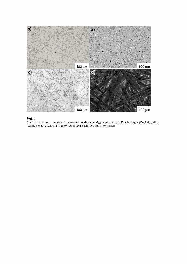
Fig. 1 Microstructure of the alloys in the as-cast condition. a Mg97Y2Zn1 alloy (OM), b Mg97Y2Zn1Gd0.5 alloy (OM), c Mg97Y2Zn1Nd0.5 alloy (OM), and d Mg88Y8Zn4alloy (SEM)
a) b)
c) d)
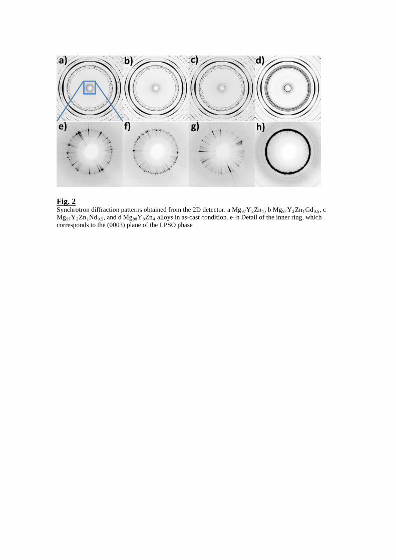
Fig. 2 Synchrotron diffraction patterns obtained from the 2D detector. a Mg97Y2Zn1, b Mg97Y2Zn1Gd0.5, c Mg97Y2Zn1Nd0.5, and d Mg88Y8Zn4 alloys in as-cast condition. e–h Detail of the inner ring, which corresponds to the (0003) plane of the LPSO phase
a) b) c)
e) f) g)
d)
h)
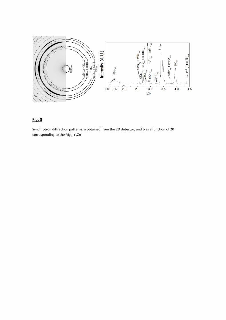
Fig. 3
Synchrotron diffraction patterns: a obtained from the 2D detector, and b as a function of 2θ corresponding to the Mg97Y2Zn1
0003
18R
1010
Mg I
I 422
2 18R
10
11M
g II 3
0312
18R
111 S
P
1012
Mg I
I 422
1818
R
200 S
P _ _
_ _
_
_ _ _
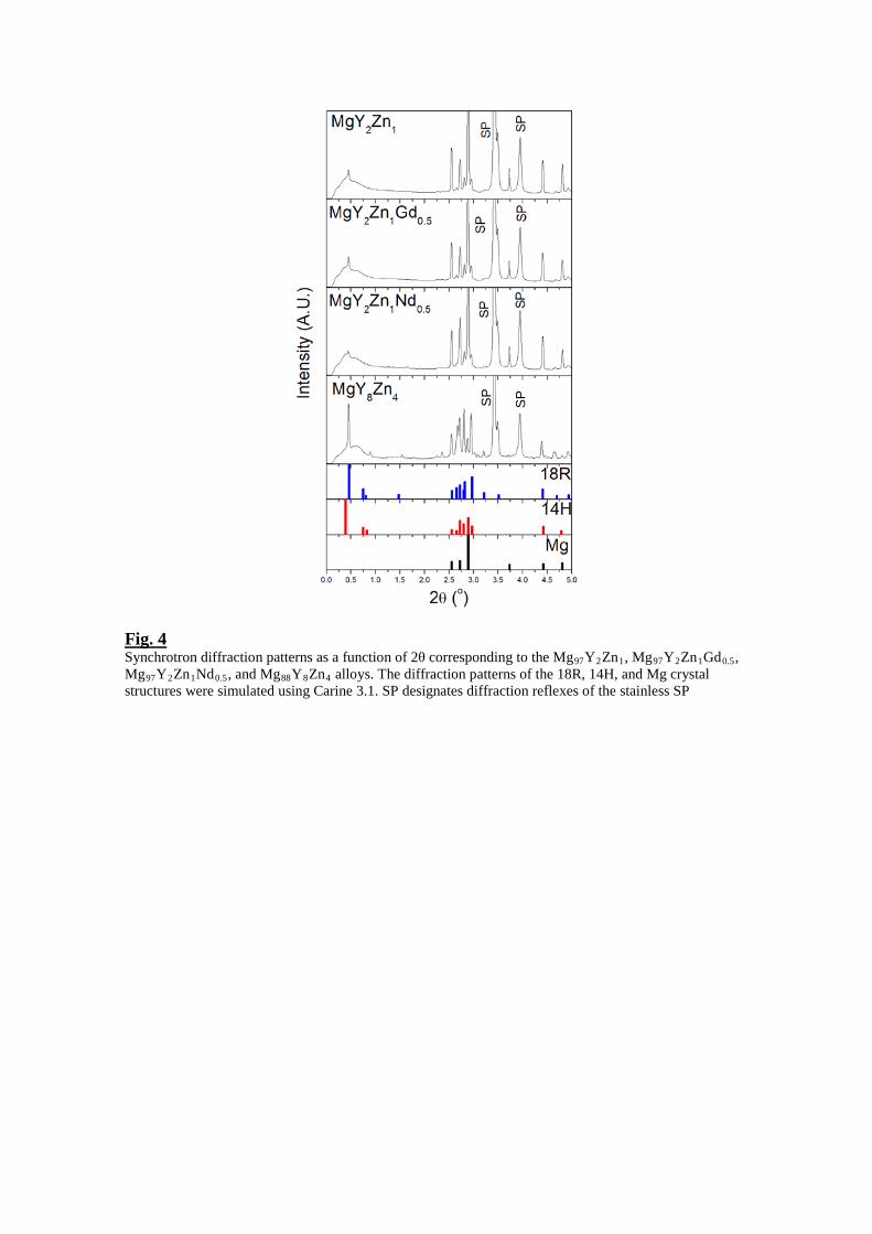
Fig. 4 Synchrotron diffraction patterns as a function of 2θ corresponding to the Mg97Y2Zn1, Mg97Y2Zn1Gd0.5, Mg97Y2Zn1Nd0.5, and Mg88Y8Zn4 alloys. The diffraction patterns of the 18R, 14H, and Mg crystal structures were simulated using Carine 3.1. SP designates diffraction reflexes of the stainless SP
SP
SP
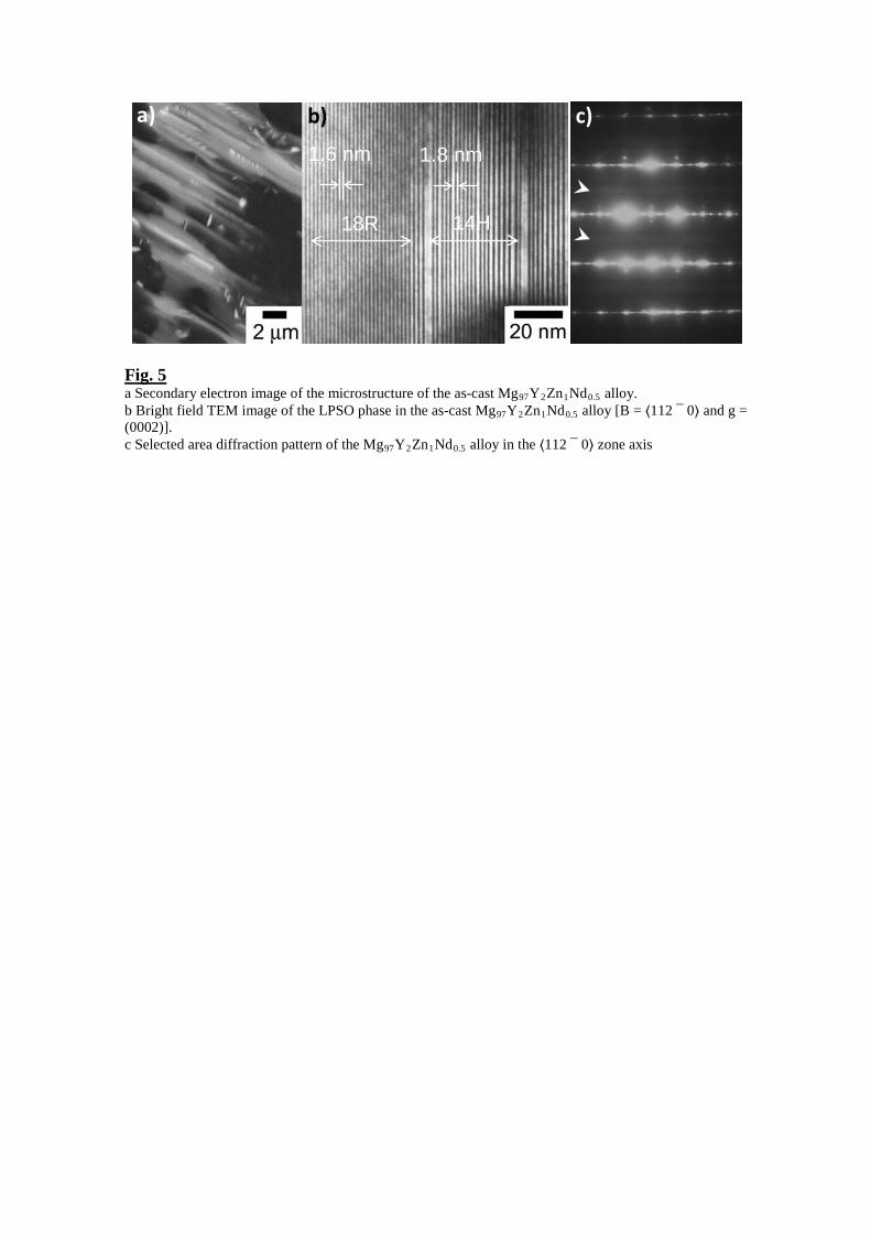
Fig. 5 a Secondary electron image of the microstructure of the as-cast Mg97Y2Zn1Nd0.5 alloy. b Bright field TEM image of the LPSO phase in the as-cast Mg97Y2Zn1Nd0.5 alloy [B = ⟨112 ¯ 0⟩ and g = (0002)]. c Selected area diffraction pattern of the Mg97Y2Zn1Nd0.5 alloy in the ⟨112 ¯ 0⟩ zone axis
18R
1.6 nm
14H
1.8 nm
a) b) c)
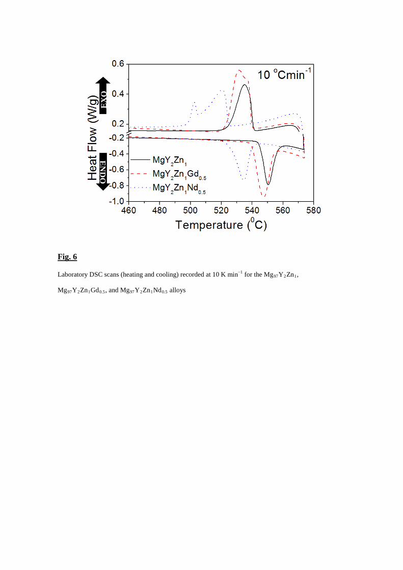
Fig. 6
Laboratory DSC scans (heating and cooling) recorded at 10 K min−1 for the Mg97Y2Zn1,
Mg97Y2Zn1Gd0.5, and Mg97Y2Zn1Nd0.5 alloys
d)
EN
DO
EX
O
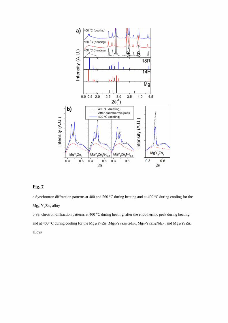
Fig. 7
a Synchrotron diffraction patterns at 400 and 560 °C during heating and at 400 °C during cooling for the
Mg97Y2Zn1 alloy
b Synchrotron diffraction patterns at 400 °C during heating, after the endothermic peak during heating
and at 400 °C during cooling for the Mg97Y2Zn1,Mg97Y2Zn1Gd0.5, Mg97Y2Zn1Nd0.5, and Mg97Y8Zn4
alloys
a)
b)
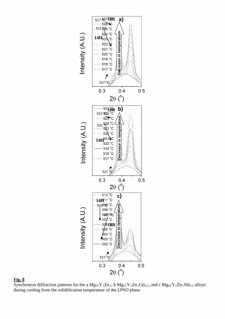
Fig. 8 Synchrotron diffraction patterns for the a Mg97Y2Zn1, b Mg97Y2Zn1Gd0.5, and c Mg97Y2Zn1Nd0.5 alloys during cooling from the solidification temperature of the LPSO phase
14H
18R
14H
18R
14H
18R
a)
b)
c)
517 ºC
527 ºC
Dec
reas
e in
tem
pera
ture
D
ecre
ase
in te
mpe
ratu
re
Dec
reas
e in
tem
pera
ture
527 ºC
517 ºC
521 ºC
521 ºC
502 ºC
507 ºC
512 ºC
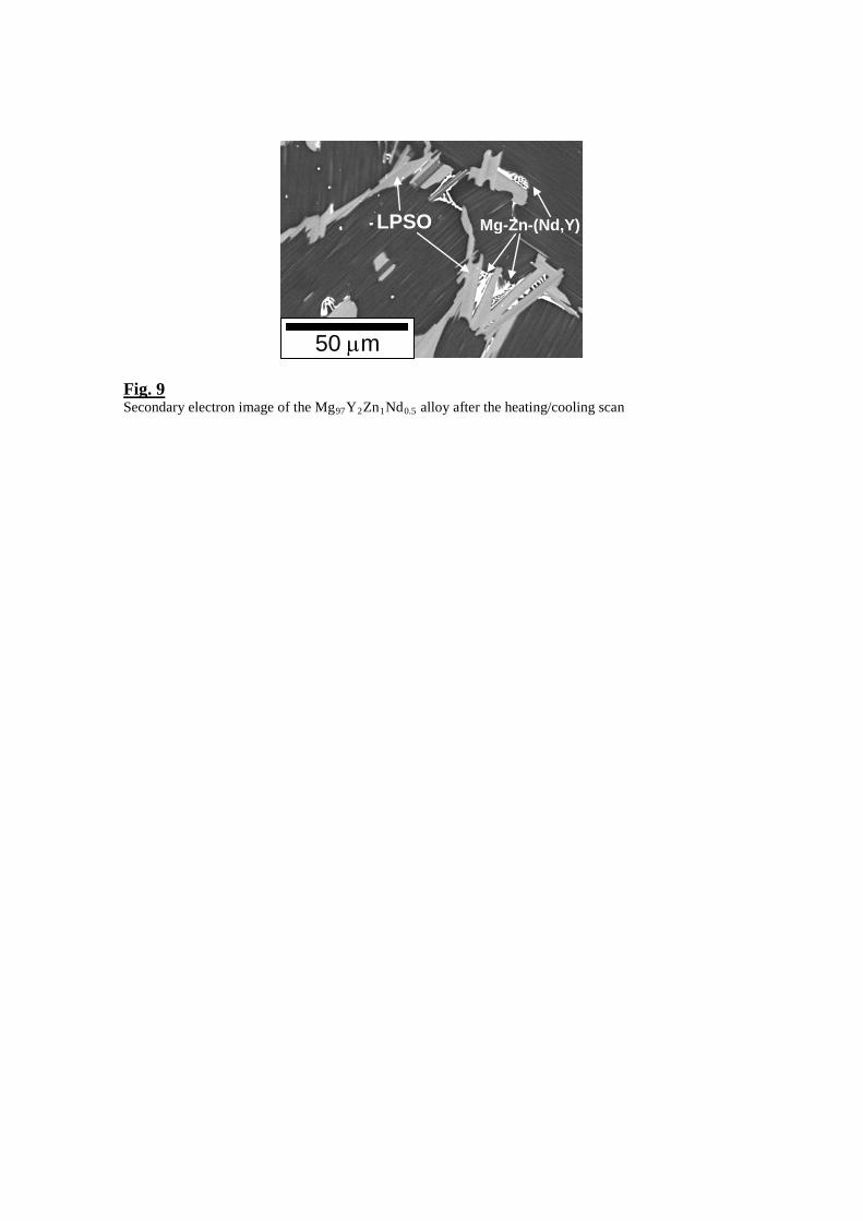
Fig. 9 Secondary electron image of the Mg97Y2Zn1Nd0.5 alloy after the heating/cooling scan
50 µm
LPSO Mg-Zn-(Nd,Y)
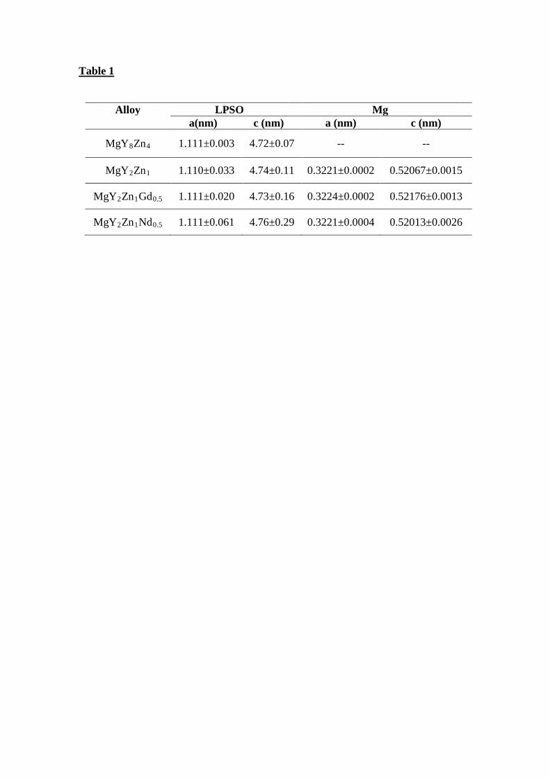
Table 1
Alloy LPSO Mg a(nm) c (nm) a (nm) c (nm)
MgY8Zn4 1.111±0.003 4.72±0.07 -- --
MgY2Zn1 1.110±0.033 4.74±0.11 0.3221±0.0002 0.52067±0.0015
MgY2Zn1Gd0.5 1.111±0.020 4.73±0.16 0.3224±0.0002 0.52176±0.0013
MgY2Zn1Nd0.5 1.111±0.061 4.76±0.29 0.3221±0.0004 0.52013±0.0026
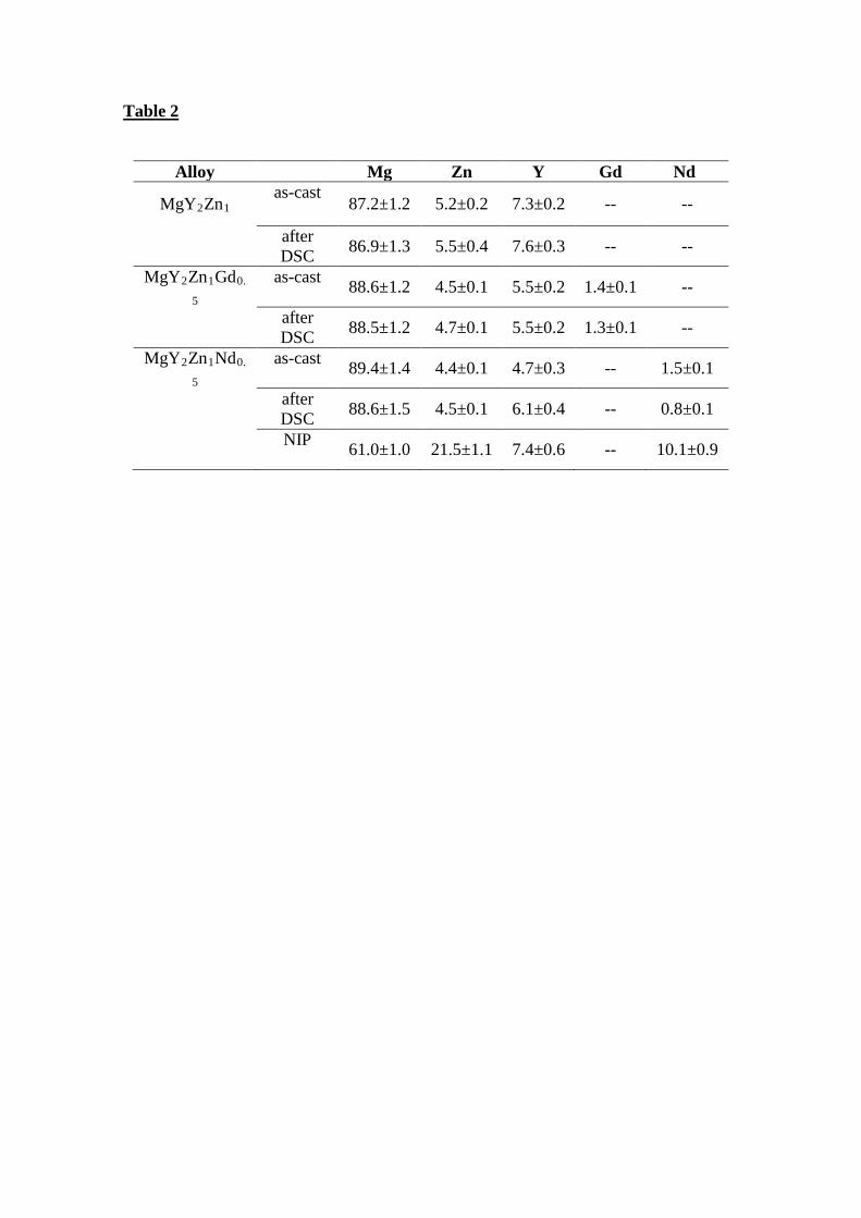
Table 2
Alloy Mg Zn Y Gd Nd
MgY2Zn1 as-cast
87.2±1.2 5.2±0.2 7.3±0.2 -- --
after DSC 86.9±1.3 5.5±0.4 7.6±0.3 -- --
MgY2Zn1Gd0.
5 as-cast 88.6±1.2 4.5±0.1 5.5±0.2 1.4±0.1 --
after DSC 88.5±1.2 4.7±0.1 5.5±0.2 1.3±0.1 --
MgY2Zn1Nd0.
5 as-cast 89.4±1.4 4.4±0.1 4.7±0.3 -- 1.5±0.1
after DSC 88.6±1.5 4.5±0.1 6.1±0.4 -- 0.8±0.1
NIP 61.0±1.0 21.5±1.1 7.4±0.6 -- 10.1±0.9