Embed Size (px)
Citation preview

U ~~'CATMIGz MhTI'TTE F TECHNIOLOGYDebp llt..e .± f.eci:haical Engineeringg .Pittibiirgh 3 Pennsylvania
FIN~AL RMDORT
ýOctober "31, 19514,
INVMTIGATION OF.GALLING AMV FRICTIONCBARACTBRISTICS OF TITANIUM ALLOYS
TO
VAT~rPWr(M ARSENAL,Watertomn.72 -Massachusetts
BY DTICELECTE
RBER Wv. GAntARDMA2
CONTRACT NO. -DA-36-0o61-ORnD-3614 WAL REPRT, No. 1401/615/37
One
'a/Cb4/9,vWeL CO

IIi,
I FINAL RPWORTOctober 31, 1954
Carnegie Institute of Technologyr Pittsburgh 13, Pa.
INVESTIGATION OF GALLINu AND FRICTIONCHARACTERISTICS OF TITANIUM ALLOYS
BY
, R W. GAYLORD
This worl was performed under technical supervision of T CWatertown Arsenal Laboratory ELEO .
Contract No. DA-36-061-ORD-36. MAY 2 6 V2WAL REPORT NO. 401/65-37Dept. of Army Project Io. 593-08-021
Ordnance Research and Development Project No. TB4-15 A
Pittsburgh Ordnance District - 200 Fourth Avenue, Pittsburgh 22, Pa.
OBJECT
To study the galling and dry friction characteristics of titaniummaterials.
3SUMMARY
The results of studies made to establish criteria for galling arepresented. A method for measuring the interface temperature betweentwo metals during dry rubbing is discussed. Results of rubbing testsof unalloyed, alloyed, and surface treated titanium specimens are=!I-.' •-given. The degree of improvement in friction and galling characteristicsafforded by surface treatment is determined.
Thi document has been approvolfor public ieleose ad a sole; itsidistribution is unlimited.

Ll1..
TABLE OF CONiETS
Page
CONCLUSIONS I
I INTRODUCTION 2
II APPARATUS 2
III GALLING CRITERIA 34
Slider Blocks and Rod Tips 3
Extended Time Galling Tests and Detection of Variationsin Normal Load 3
Surface Roughness
V Coefficient of Friction 4
The Relationship Between Roughness Coefficient ofFriction and Galling
V IV SLIDING FRICTION AND INTERFACE TEMPRATURE
The Dynamic Thermocouple
V SMWFACE TREATED SPECIMENS 6
vi PERSONEL 9
VnI BIBLIOGRAPHY 10
, Distribution List 70
Accession For
VI'C TAB~
S •./ • TI. i•(I•D) 10 t r I NhI t i~ ,u/Plvililabiltty Codes
"', ' ii / '
U i~ ;c :In

1
I
CONCLUSIONS
1. The normal loads and speeds that cause galling of unalloyed titariumrubbing on unalloyed titanium do not depend significantly on theapparent contact area of the rubbing specimens, but with larger areas
* galling damage appears to progress at a slower rate.
2. When galling of a titanium slider block specimen rubbing on a steelplate occurs there is a significant increase in the amplitude of thefluctuations in normal load which may be detected by a piezo-electriccrystal. Galling damage may increase in serverity over a period often minutes or more.
S3. Heavy galling of metallic surfaces in dry rubbing is accopanied bya large increase in surface roughness and an increase in thecoefficient of friction which becomes more or less independent ofload. When there is no galling the coefficient of friction is notreproducible and increases with time of rubbing.
4. When there is no galling a "dynamic thermocouple" formed by thejunction of two dissimilar metals rubbing over each other may be
,* used to get a fair estimate of the average interface temperature.A dynamic thermocouple will produce a randomly fluctuating componentof voltage that increases to a much h•igher value when galling occurs.
S5. The improvement in galling characteristics of titanium alloysafforded by surface coating and nitriding is significant.
I
7 '

2
I1 INTRODUCTION
This is the final report on the project INVETIGATION OF GALLING ANDFRICTION CHARACTERISTICS OF TITANIUM ALLOYS which is a .4ontinuation of thework done on the project GALLING AND SEIZING CHARACTERISTICS OF TITANIUM BASEALLOYS (1), October 15, 1951 to June 30, 1953. This report covers the periodfrom July 1, 1953 to September I, 1954.
This project has, but is not necessarily limited to, the followicgobjectives:
1. Determine the galling and friction characteristics of titaniumand titanium alloys.
2. Establish satisfactory criteria for the galling of titaniummaterials.
3. Determine, quantitatively, factors affecting galling character-istics; such as load, speed, thermal effects, and time ofrubbing.
4. Evaluate the degree of improvement in galling resistanceafforded to titanium by various surface treatments to besuggested by Watertown Arsenal Laboratory. These may includenitriding carburizing, phosphating, oxidizing and electro-deposited coatings.
II APPARATUS
The test apparatus is essentially the same as that described in the"final report of the previous contract (i), June 30, 1953, Modificationshave made the testing machine adaptable to a greater range of loads, speeds,
t{ and types of tests.
A plate specimen is attached to a revolving face plate and is rubbedagainst a stationary test specimen, (see figures 1 and 2). The stationarytest specimen is held by a loading arm so that it traces a circular pathon the plate specimen. The loading arm contains an adapter that will holdboth rod and slider block type specimens. A ring spring applies the normalload to the loading arm which is free to pivot about its base in the planeof the normal load. The normal load may be determined either by a dialindicator which measures the compression of the ring spring or by balancingthe ring spring force with a weight and pulley system.
The entire normal load apparatus is attached to a platform which canoscillate in a plane parallel to the plate specimen. An arm which is attachedto this platform rests on a strain ring equipped with SR-4 strain gages, andis aLtached to a dashpot for damping. The strain gauges make it possibleto record the strain ring deflection, -hich is proportional to the tangenttalforce on the rubbing specimen. This strain gauge reading may 'be continuouslyrecorded on a direct inking cocillograph, observed on the screen ofl anoscilloscope, or indicated on the scale of a vacuum tube voltmeter. A setof known weights which axe placed on the strain ring may be used for cali-bration. The loading apparatus has been designed to reduce transient effectsand chattering. Relative rubbing speeds ranging from almost zero to 2000feet per minute are available.

III GALLING CRITERIA
Part of the research consisted of studying phenomena that are relatedto galling during the dry rubbing of metallic surfaces. It would be desirableto have one or more methods that would consistently define galling damage anddetermine when it occurs.
Slider Blocks and Rod Tips
In the work done on the preceding contract, the specimens that wererubbed on the plate material were 1/16 inch diameter rod type. Becau;e theseshowed some tendency to dig into the plate material unless the rod tip surfaceswere very carefully prepared, it was decided to use slider block rubbingspecimens. The slider block specimens (see figure 3), were held in place bysteel jaws and rocked on a pivot through which the normal load was applied.The pivoting action insured good contact of the slider block surface againstthe plate surface. A chamfered leading edge and rounded corners preventeddigging in. Rubbing tests of Ti 75-A slider blocks on Ti 75-A plates weremade to find out what speeds and loads would produce visible gallng damageof the slider blocks and plate surfaces. The test procedure ws to operateat a constant rubbing speed and gradually increase the normal load at 15 minuteintervals unbil gal-ling occured. On the previous contract a similar ty-Ae oftest had been run for a 1/16 inch diameter, Ti 75-A rod tip rubbing on aTi 75-A plate surface. In figure 4, the results of the two tests are compared.The galling limit normal loads and speeds are similar for the slider block andthe rod tip, but the surface area of slider blocks is 0.047 square inches whereasthe surface area of the rod tip was only 0.003 square inches. Once gallingbegins, however, galling damage progresses at a more rapid rate with the rodtip than it does with the slider block.
"Extended Time Galling Tests and Measurement of
Variations in Norma]l Load
Ti 75-A unalloyed titanium slider blocks, with normal load being applied
by a piezo-electric crystal, were rubbed against a steel plate at speeds of10, 25 and 50 feet per minute and normal loads of 4, 8, 12, 16, and 20 ouncesfor a period of one hour for each load and speed. The arrangement of the piezo-electric crystal is shown in figure 3. The crystal develops a fluctuatingvoltage that depends on the fluctuations in the force that the slider blockpivot exerts on the crystal. This voltage depends on the roughness of the tworubbing surfaces as well as on the magnitude of the average normal load, therubbing speed, and the mechanical properties of the slider block holder system.
IFor a given amount of roughness or galling of the rubbing surfaces,light loads and low speeds produce considerably less voltage than do high loads"and high speeds. However, for a given normal load and speed the crystal voltagegives a relative indication of the amount of galling damage that has taken place.rThe results shown in figures 5, 6, and 7, are significant in that they show a
r substantial increase in the voltage for a given load and speed as galling damagep'ogresses, and that galling damage appears to increase in serverity over aperiod of ten minutes or more.

4
Surface Roughness
A Brush Electronics Company "Surfindicator", Model BL-II0, roughnessindicator was used to see hcor surface roughness compared with galling damage.This instrument measured the average surface roughness of the slider blocksand plate specimcns. Surfaces that were surface ground or polished withcrocus cloth ranged in roughness between 4 and 7 micro-inches. After thespecimens were rubbed, a visual change in the appearance of the surface couldbe observed when the roughness had increased by 3 to 4 micro-inches. Veryheavy galling caused the surface roughness indicator to show a roughness in-crease of 20 micro-inches or more.
Coefficient of Friction
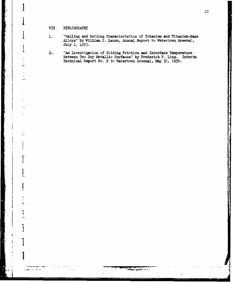
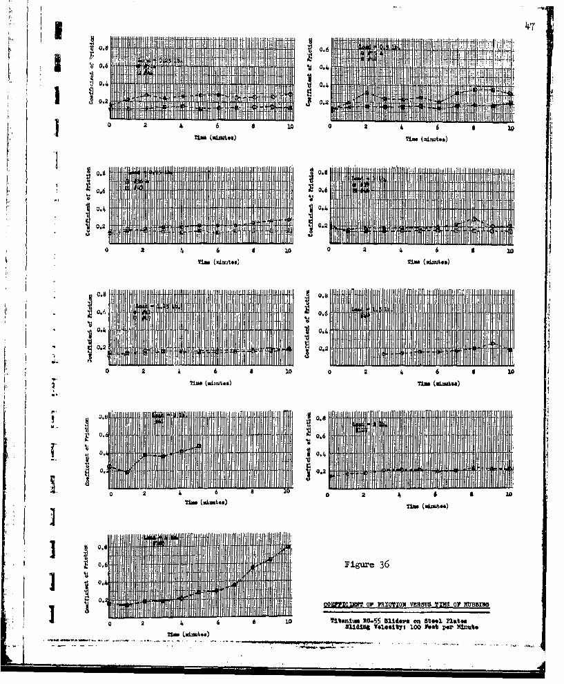
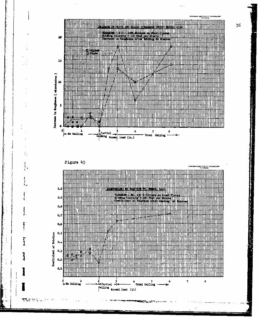
During many of the rubbing tests the coefficient of friction wasmeasured. At the begiuning of a rubbing test the coefficient of friction wasrather low for the dry rubbing of metals. As rubbing continued in the absenceof galling the coefficient of friction would gradually increase. (See figures14, 16, 26, and 36.) When severe galling occurs the coefficient of frictionincreases to a mucb higher value (figures 13, 15 and 45), which seems to bemore or less indtependent of the load. Figure 8 shows the frictional force forTi 75-A rod tips rubbing on RC-55 Plates.* Over the range from about 1 lb.normal load to 10 lb. normaJ. load, heavy galling occured. In the range of0 to I lb. norml load thfe coefficient of friction is quite random. In thisrange heavy galling does not talte place. In the work done on the presentcontract the sensitivity of the friction load apparatus was increased so thatmore accurate measurements could be made in the range of normal loads wheresevere galling does not occur. It was Oound that the coefficient of frictionwas not constant or reproducible In this range. It is probable that in theabsence of galling contaminants which serve as lubricants are always presenton the rubbing surfaces no matter how carefully they are cleansed with carbon-"tetrachloride. As the rubbing time increases some of the lubricant is wornaway and the coefficient of friction increases. The increase in friction whenheavy galling begins may be due to true metal to metal contact replacingcontact between dry lubricated surfaces.
The Relationship Between Roughness, Coefficient ofFriction and Galling
Figures 13, 15p 25, 35, and 45, show how the coefficient of frictionand the increase in surface roughness vary with the normal load for steel.Ti 150-A, RC 130-A, RC-55, and RC 130-B sliders after rubbing on steel plates1 for 10 minutes at a speed of 100 feet per minute.
There is considerable correlation between the coefficient of frictionand the increase in surface roughness. The condition of the surfaces after
* This work was done on Contract DA-36-O61-ORD-112. Galling and SeizingCharacteristics of Titanium and Titanium Base Alloys.

Irubbing is arbitrarily classified in three types (see figures 9 and 10), whichare:
1. No Galling. The plate and sllder, except for some shininess,show no visual surface damage. The surface roughness increasesby no more than 1 or 2 micro-inches and in some cases the surfacemay become smoother. The coefficient of friction is neitherconstant nor reproducible and seems to behave as though a drylubricant were present between the rubbing surfaces.
2. Partial Galling. Visual damage occurs over parts of the rubbingsurfaces but does not extend completely over the entire contactarea. Scratches appear and portions of the rubbing surfacesalternately become roughened and then smooth out during rubbing.During much of the time the coefficient of friction will besufficiently low to suggest the presence of some lubricationbetween the rubbing srfaces.
3. Total or Complete aL•ling. At the beginning of a test partialgallin-gwith iall scratches or rough portions will appear onparts of the rubbing track. However, as rubbing continues theywill not be smoothed out, but will spread over the entire areaof the rubbing surfaces. When this happens the coefficient offriction will increase to a value that does not depend greatlyon normal load or time of rubbing. Powdered metal appears onthe plate and the plate and slider material wear away rapidly.
p IV SLIDING FR~ICTION ANlD IN~TERFACE TME'RA'IRE
An investigation was made of the relationship between friction andthermal effects at the interface of a pair of dry metallic surfaces in slidingcontact with each other. The purpose of this study was two-fold. First tosee if means could be found to gain a better understanding of how the frictionalbehavior of dry rubbing surfaces is related to the interface temperature andsecondly, to establish a criterion for galling through the observation ofthermal effects.
A complete report of this work is presented in Interim Report No. 2,"An Investigation of Sliding Friction and Interface Temperature Between Two
Dry Metallic Surfaces (2)."
Dynamic Thermocouple
The use of a "dynamic thermocouple", formed by the Junction of twodissimilar metals in sliding contact with each other, as a means of measuringthe interface temperature was investigated. This type of thermocouple wascompared with an ordinary "static thermocouple" formed by two dissimilar
t metals brought into intimate contact by means of pressure or fusion.
To evaluate the behavior of a dynamic thermocouple an experiment wasperformed. To reduce the number of variables in the test only one pair ofj dissimalor metals was used. Constantan and steel were selected because oftheir high thermoelectric properties. No titanium materials were tested;however, certain combinations of titanium and other metals will producc a
S1 thermal e.m.f.
,•!• .. . . .... .. ... .......... . .... •= =• • • •=A • -

6
In the test setup shown in figure 11 a constantan rod tip is rubbedagainst a steel plate to form a dynamic thermocouple. A fine wire rotatingin a mercury bath is used to form the second moving contact. One noral loadof 0.5 lb. was used. During rubbing the voltage output of the dynamic thermo-couple, ed was a randomly fluctuating voltage which was divided into twocomponents by the circuit shown in figure 12. There was an alternating com-I ponent of voltage, e'd which was separated from ed by an a-c amplifier andrecorded on an oscillogram and a direct current or constant component Ed whichwas separated from ed by a filter and measured by a potentiometer.
The d-c component Ed was investigated to see if it could be used as ameasure of the interface temperature of the two metals sliding over each other.To do this a cone-shaped constantan rod was rubbed on a steel plate with thesmaller end of the cone making contact with the steel plate. A "staticthermocouple" was placed in the rod at a known distance back from the plate.During rubbing heat generated by friction caused a rise in the temperatures ofthe static thermocouple and the interface of the dynamic thermocouple. Boththe dynamic thermocouple and static thermocouple voltages were measured . Thetemperature measured &b the static thermocouple was used to calculate the time
space averaged interface temperature at the dynamic thermocouple. This temper-ature was found to be In fair agreement with the temperature corresponding tothe d-c component of the dynamic thermocouple voltage when no galling occurs.
The a-c voltage e'd appeared to depend on load and rubbing speed andwas observed for both dissimilar metals, constantan rubbing on steel, and forsimilar metals, steel on steel. This voltage shows promise as a criterionfor galling because it becomes much higher when there is visible galling.
The dynamic thermocouple was used to obtain results, which are not yetconclusive, on the determination of the fractions of the heat generated byfriction which go into the plate specimen and into the specimen which rubs onthe plate, and on the effect of interface temperature on the coefficient offriction.
V SURFACE TREATED SPECIMENS
Slider block specimens of titanium and titanium alloys, Ti 150-A, RC-55,RC 130-A and RC 130-B, with four different types of surface treatments werereceived from Watertown Arsenal Laboratory. The surface treated materials wereto be tested to determine their friction and galling and seizing characterisbics.The degree of improvement in resistance to galling afforded by the surfacetreatments was to be determined.
Because of the number of specimens to be tested the variables in thetests were restricted to the normal load. All specimens weve rubbed on C 1019steel plates that were surface ground to a roughness of 5 to 7 micro-inches.The slider block specimens had a rubbing surface of about 3/16 x 1/4 inches"with the corners chamfered and polished to prevent digging in. A rubbing speedof 100 feet per minute was chosen because it was thought to be high enough that"galling would not be affected by small variations in rubbing speed. The specimens
were rubbed for 10 minutes. Untreated specimens that will eventually gall ata given normal load will generally do so in this length of time, however, surfacetreated specimens that last ten minutes might fail over a longer rubbing periodas the surface treatment wears away.
I!

1 7
To find the degree of improvement in resistance to galling afforded by1 the surface treatments, untreated specimens were tested in the same manner as
the treated ones. Steel on steel was also tested.
The four types of surface treatments are: Treatment AIl Treatment B
Nitriding 16 hours nitrogen at 16000 F.Nitriding 72 hours nitrogen at 16000?. plus 16 hours partial
Te t pressure nitrogen at 16000F.and will be described in the order listed above.
•, Treatment AL. Surface treatment
(a) Fluoride Phosphate coated.
(b) Heat treated, 5 hours at 800 F.(c) Molykote G lubricant
C Specimens having this treatment have a dull black appearance whichbecomes shiny black after rubbing. A surface coated slider block specimen willleave a shiny black path on a steel plate indicating the presence of a dry
lubricant which is rubbed off the slider and deposited on the plate track.As shown in table I, treatment A enables titanium' and titanium alloys to with-stand rubbing at much higher loads than the untreated specimenk. In the caseof RO 130-B no galling occured at a normal load of 10 lb. Higher loads werenot tried because the testing machine was not set up to apply higher loads.The results indicate that the rubbing surfaces were completely lubricated andthere was no metal-to-metal contact until galling occurs. Galling seems to take
1 place when the lubricant is rubbed off on a certain portion of the slider. Whenthis happens there is galling and scratching in this area which quickly spreadsover the entire rubbing area. The coefficient of friction rises to 4 value thatcorresponds to the galling of untreated specimens. The coating in treatment Ais rather thin. ' A small amount of sanding with crocus cloth will wear it awayto the extent that the slider blocks will gall at much lower loads.
Ui The coefficient of friction before galling takes place is much largerU than it would be for surfaces lubricated with a wet lubricant such as grease
or oil. It varies considerably from test to test but is generally lower thenit is for severe galling of the corresponding urtreated specimens.
Treatment BSurface Treatment
(a Fluoride Phosphate coated.1 (b Treated with layer of Mo S2 and phenolic resin.(c Air dried 6 hours, cured 12 hours at 3000F.(d Mo S2 - Resin layer lapped to a thickness of 0.003"-0.004".
The specimens were received in the form of slider blocks which were cutfrom surface coated strips. The specimens showed a poor mechanical bond be-Wteen the metal and the surface coating. The cutting had loosened some ofthe coatings so badly that they fell off. When tested none of the specimensgalled at a normal load of 10 lbs. The coatings were much thicker than those
]1 for treatment A. It would probably take a much higher normal load or longerS..rubbing time to wear the coatings away and make the specimens gall. The
-"m"

8
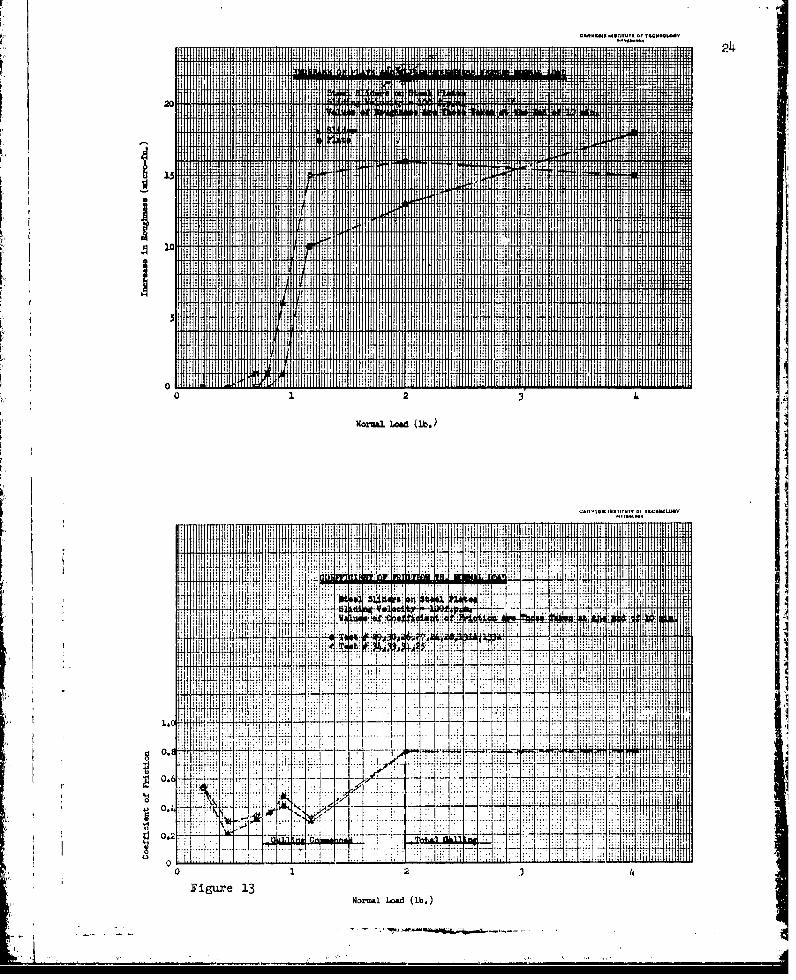
frictional characteristics are similar to those for treatment A when no gallingtakes place. Figure 56 shows the black smear which is deposited on the platetrack. Figure 55 shows the condition of the slider block surface.
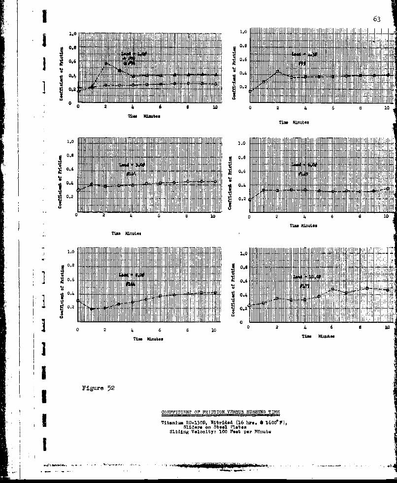
Nitrided Specimens 16 hours nitrogen at 6000 F.I These specimens were received in the form of strips which were then cutinto slider blocks. The metal had a golden yellow appearance and the sur.facewas so hard that one cut on the surface would ruin a hacksaw blade. The surfacesof the specimens were badly deformed into a concave shape. In preparing thesliders the corners were chamfered, leaving the initial contact area as untreatedmetal. When tests were run this area would immediately gall, wear away, andleave two scratches on the two outside edges of the plate track. The treatedportions of the surface would then come into contact with the plate and nofurther galling would take place. This was ruled out as being a failure ofthe surface treatment mid the spe imens were considered as having failed onlyif the galling spread over the treated portion of the contact surface. As shownin figure 58 these specimens left a black smear on the plate which may have actedas a lubricant. As shown in Table I none of the specimens galled at normal loadsof less than 6 lbs. Some specimens did not gall at 10 lbs. No correlation wasfound between the galling loads for the treated alloys and the galling loads ofthe untreated alloys which are listed in Table I in the order of increasingresistance to galling. The coefficient of friction when no galling took placewas much higher than it would be for wet lubricated surfaces but was lower thanthe coefficient of friction for untreated alloys. When galling takes place itbegins on one portion of the contact area and spreads across the entire contactarea. When the treated surface wears away completely the coefficient of frictionrises to a value which corresponds to the coefficient of friction for the gallingof untreated specimens.
Nitrided 72 hours Nitrogen at 1600 F. plus 16 hours partial pressurenitrogen at 1600 F.
The appearance and frictional characteristics of these specimens weresimilar to those for the previously described nitrided specimens. The scope ofthe tests was not sufficient to determine any significant difference betweenthe two types of Nitriding.
'1
.,.

1 9I
VI PERSONNEL
I The personnel who have worked on this project are Eber W. Gaylord,Frederick F. Ling, Yih-O Tu, Allen Selz, Latif Jiji, and Michael Rabins.
I Professor D. W. Ver Planck and the late Professor Wayne S. McKee,have given valuable advice and criticism.
] Bespectftlly Submitted,
CARNEGIE INSTITUTE OF TECHNOLOGY
Eber W. GuLylordAssistant ProfessorDept. of Mechanical Engineering
D. W. Ver PlanckHead, Department ofMechanical Engineering
LZ
i.
1 10I
VII BIBLIOGRAPHY
1 1. "Galling and Seizing Characteristics of Titanium and Titanium-BaseAlloys" by William C. Leone, Annual Report to Watertown Arsenal,
S1 July 1, 1953.
2. "An Investigation of Sliding Friction and Interface TemperatureBetween Two Dry Metallic Surfaces" by Frederick F. Ling. InterimTechnical Report No. 2 to Watertown Arsenal, May 31, 1954.
'I
ii
* I
Ip
I-.,,- t~
' 1

l11
TABLE I
Loads that cause galling for titanitm alloys and surface treated titaniumalloy slider blocks rubbing on steel plates.
Rubbing velocity 100 ft. per minuteRubbing Time 10 minutes
Load thatMaximomi Load causes total
Slider Block Material for no Galling GallingLB. LB.
Ti 150-A untreated 0.5 1.0RC 130-A 0.5 1.0RC 55 0.5 1.5Steel " 0.75 2.0RC 130-B 2.0 3.0
Ti 150-A
Treatment A *4 6Treatment B greater than 10
(Nitrided 16 Hre. N2 "t 1600°F.) greater than 10(Nitrided 72 Hrs. N2 at 16000F.
+ 16 Hrs. N2 at Partial Pressure 16000F.) greater than 10
RC 130-A
Treatment A *4 6* Treatment B greater than 10
(Nitrided 16 Hrs:. N2 at 16000F.) *6 8(Nitrided 72 Hrs. N2 at 16OO°F.
+ 16 Hrs. N2 at Partial Pressure 16000F.) *8 10
RC 55
Treatment A *6 8Treatment B greater than 10
(Nitrided 16 Hrs. N2 at 16000F.) *8 10(Nitrided 72 Hrs. N2 at 16000F.
+ 72 Hrs. N2 at Partial Pressure 16000F.) greater than 10
RO 130-B
Treatment A greater than 10Treatment B greater than 10
S(16 Hrs. N2 at 16000F.) *8 1016 Hrs. N2 at 16000?.
4 + 72 Hrs. N2 at Partial Pressure 16000F.) *8 10
* The material was not tested at loads in between loads for no galling andloads for total galling.
.j

112
I
Figure 1.Photograph of the Friction Apparatus
1 .
* -l
Il
<1_ _ _ _ _
________________________
!I, ., I

1Lu
el..l
C9U
____w

1 14
I SLIDER~ BLCK SPEC IMAN HOLDER WI1TH-P EZOELECTRUCCHYSTAL
I' II-If: z
In
* ADJUSTABLEQU)IDES HOLDSLIDER BLOCK)N PLACE
SLIDER BLOCK
~1AL LAD 4.5 CAFER
[c
PIEZOELECTR)C CRYSTAL-ELET1 ALCNUTR
Ei ____ICALCODCTR
SECTION AA
Figure 3 Diagrami of J31idor Holder' with Piezoeluctrio Crystal.

1.5
'41 Z: z. _oa
Szcr.
000
0, N.. F.I, .- -- - - -°
•,• m • •'
L 0
I!/

116
I --- RELATIVE ROUGHNESS BETWEEN TI7-7ASLIXER BLOCK AND STEELjj PLATE FOR RUBBING
"SPEED OF /0 FTA/IN.
AJ
.1 1U
- - - -.-. NORMA L.. LOADS
- -- dox
li.lk,, J• - - -'- -- ---------- "-------
.J - - . ----------- ---.-- ------- -
Ao .--'l' ',T!" \ ... i ... , 6...0... .. ..
/0 20 30 40 so 0R RUBI NQ TIME, (Nl/NJ
Figure
:< I- _ _ _ _
f ' ,• "' W ,,ir:•T', #''•'•

J.7
RELATIVE ROUGHNESS BETWEEN TI - 75A%n• SLIDER BLOCK AND STEEL
PLATE FOR RUBBING--- SPEED OF 25 "tAN,
.- I
-c OE- - -c
oi-
•4 oz
.-.-.-...--.- .. ...-. -...
0 I I I
-- I
2 0
AA
RUBBIN- TIME. (m/ N.)
"FRAure 6
-- / --- 12,' 1'ox

| 18
RELATIVE ROUGHNESS SETWEEN TI-75 SLIDER BLOCK& STEEL PLATE FOR RUBBINW p.ED OF 0 0r%
u OF SCOPE
---- - 4 oz,•15 ... ~ ~. .. -~--iaoz
-J ', ,.,--- J6 0 ~oz,
J1 ax- - /
,IL
,0it -
- /
w/
i~ ~~ý 4' - -- "
") 4
T3 1m
( I tq,LU" / .. ... 4
i ul5 ..... . . .
I -,
K ] o° J• - 1 L. °,o.Rt0 50IN@ TIME (MJN.)
'.':"i " FI gute '7
-II'

19
'1O 0-1
I]~'O O ___ _ ___ _ __

20
MICROPHOTOGltAHS OF TITANIUM ANDTITANIUM ALLOY SLIDER BLOOKS (lOX)
t/ I a, Some scratches - The bulk,~ ~pP~of the surface iu unchanged
b. Early stages of gallingPartially galled
06 Completely galled
Figure 9

21TYPICAL MIHO0PH0TOGp~ap
OP Sj E-'A~ ITS ~ C TF S rG aEaWIT ?IA~~J~AND TITAMIUMp ALLOySLIDER BLOCK Sp~JxIMSq
as UnluSed plAt.4*
____ ____ ___ ____ ____ ___ ____ ____ ___ b. Par 't ±ia l Sa~lled Plate tl'ao k.,
0~CoinP1etel gaxlled plate traok.
11 gu~re 10

22
Back-up Plate on theFriction Ap~paratus
Dynamic ThermocooupleJuncti on
Rod Specimen Plata Specimen
FlexibleI. Cable
Paho
j i'iui~.11 cchoinatic Dlisgram of Dynaumic 11hernio00uple Se-up.

L- C }dZeads aind NorthropIPotenti orniotr(rciadinga to nearest0.025 11n0ve)
O illogap
0#~ P
Figuro 12 Sohommtic Diagrami of' Arrarigament For Separating~19 0ad into A--C and D~-C COonlponanta.
20 mm f INRA
MI I 1 1
flux 131HI
HIL WRI

qiai
0.
00 2 10 26 91 ~Tim ( min.) Tim. (min.,)
1151iii11 iTr111 ff w i 11 1
00 2 4
TmTimm (min.) 4 (~ )
I. I. i
04+1 IN Il I fI
00 2 a 00' 260
Tim. (z"ii) Tim. (min.,)
Ill Idgir 11111IN
0.%A~l0~ o.? IOIO f .6TM FRlI~f
0.4. 0ldr nSte lt.4
0.2ui eoot ii:.~~ - .
......

CARN9419 INIUTITUTE or ICCHNQLV4V 26
A I
1.lM ll1. 0Jl
IllMIT
illa 3. ;otw 5'"~n 11111 l M4111111 IIIH I Illl
Jill
0H No -fPartial 1. Total Galig . 2rguei
Normal Load (lb.)
CA WlII IN.IUt F KWP't

ii 27
0.8 . I I
IN 1 11 11 JjRI I
0.6~~ I NI dHI .
1.0
0.4 ~
0 2 4 6 a 10 0 2 4 6
T'im (minte) Time (minuties)
o. M il 111 6. If JI0 a
Tim (mizates) Tilas (minut~es)
F"igure 16
Tt~aniuim TX-150A Sliders on st**I. P1&tss7 Slitding VolooitVy l00 Post, por MiLnute,

R TIMl Ii
HI
10
2 3.
I oNaml L.od (Lb.) TO IL V
1.0 ...
0.71
IIi
0 0.334 5
0.2i .o~ . ~ ~ .L)1~ ~±
U
'I*.

29
ii!
0,6.,
0 0. *a
0 2 4 6 8 20 0 2 4 6 a 20
Time Min~ut~es i iue
1 0 ,11I 11111.0
0.4
0 6
02 4 6 831 461
Tims Minutes Tim miniutes
0.6
F'2 4 6 8 10
Tim# Minutes
III
TitanwiTr P-150A, Iharfaes, Tramn AoSliders on Stool Plates
I' Sliding Valooityt 100 Post per Xirmt.

CA~AI(,.r~~t b TCHULth30
.I
MIt it
A
0 1 2 3 4. 5 6 7 d 9 10ZNorma14 Lod .b.)
Figure 19
0.6
005
j0.3
0O. 1 1 6 7 0 91
Moruui Load (1b.) ...

31
Hil 111 Mi i
.611" 1 11 11 11 110.8 N pl'
0 24 6 810 0 2 4 6 810
Tim (minuteus) Tim (miutoo~e)
'11111111 ItMT~lrI IMMI M MIIII RUll iiTM IITI
0.4 09
2a 1 0 0 2 21
Tim (minutes) Tim. (minute$)
0.4 9l '1F
N0~ 1UT
0 2 4 6 810
Time (minutes.)
0IMPM00OfMTION VIPH811 BNG
Titaniumn TT-150A Surfsoo %hroatomot H,
DFiguro 20 Sldn Volooityi 100 Poet ýr Mnut

.2m j 3
I CAN&K ~S7Wtg TMI 1.. ........
114 1f . HIMIM1Tl
.0S ~ * a 4 ; 111:10 2.
............ i.).....
J #IM MI ttQ W Lk
20,1
049
0j
0 1 2 4 5 6 7 a 9 2.0
sw"Iu Load (Ibs) . Figure 2-1

33
o 24t 6 i1
0.801
~0.4 0.6
02 4 6 10 1 0 24 6 810
'rimsi~jnutes Time xi ates
1.0 Il il1.0 . ...
0.6 0.6
0At 0.4
1 0 2 4 6 a 1 0 9 4 6 8 10
018 ... . . 0A
0', 0'
Figure 22
aOZM~TCX1QT OP PttICTION VERSUS EMR1h! IPrmfmc
!1tanmi YI-lSOA, Nitwidso (16 bras. 0 160(f P),811 tro on Steel Plato*
aliding volooltyt 100 post per Ninwbe

11,411 ý ld (11J1.)'
Ficure 23
1.0
009
007
0.5
V 0.3
9.02
0 1 2 3 a. 5 6 7 8 9 10
NmL~ad (lbv)

I 351.0 11 11111H t111 i I ii:lliIIIIII!1 . 1 M : II
I. 0.8
0a R a 11
I Tim Kiimted Timl kinuttet
. ... 1...........i...
0.6 .
0.4 .
0.2 Jil2 .i IN II *.2 'J I~i'iI~
.0. 10. ... .....
21 0.6 0.8
0.& Ii0.6
08 110
0. li Mf4. .
T~m ~n'taaTim. Kinites
Vigure 24
COU"0 MI0XW! OF MRZOTLOW MUMT18 M !TM
?ita~njujI TT-150k, witrifed (72 hrs.+16 bps.
dliding Voloiy 100 Vast per MnImts,
t . ....I . ....

IN
1MR
30.
20.
0 3. Normal Loa4 (lb. 2
Allinx-~ Toa " i

3.7
11 0W4ri I IL1 .41 r~ 1111fl 1111 11111 114 10 11-1:ý I A 1M I 11
0.1 m l10 2 i 11
1.0" .. .
0A O
0 2 4 6 a 10 0 2 46 a 10
Tim* WA~rutes) Timi (w±Kwtes)
0.0 0.s
4.
0 2 Ill 6 a 10 0 2 4. 6 810
Tia*(ronute) Tm (mtiltes
1.0 . .. . 1.0.9 0.
0.6r 266
0 .00
HO13 liders ovi Btiegi PatesTslani"~ IVd1300A TO ee erMnute

I3
0 1as 11 OW i 5f a 1111111I
KW~m 1`1d TL11V
03
... ......
111 Jill I oIICIH)M III
"....... . ....
20 f till !1-

1 0. ... .. ... 1.0 tli
0. 0.4
Od 0. A
0 10INilIm
0 2 4 6 a10 0 2 4 6 a 10
Time Minutes Tim Minutes
1.0 1.0
.0.
*0. 2 02
601 046
0 2 4 6 9 10 046al
4iwMnts i iue
I,0.8 ?IINi ~PIIIO E~~~E~GTM
Figre23TitnlnnRO130, iw~o i~~0.6 A
0.4 ~ r ..... .....PteS1~4iig ~loity: .0 ......... ~ it
I0.-0~- '

CARMfal C IUICom~TE Of VEc"-NOI.OG
I4
[ittINUITT OlP lISCWWW
1.0
Egl
2 3 7 a 91
I ~Norrul 1"di (Lb.)
Figur 29

4141
0.2
o.66i
40.2 0.4
0 00 2 46 10 .1.0 3..0
0.4 0.4
106
S0.4
., 0.4
0 2 4 6 a VX
Time Hinuites
* ~~00H~PVTInINT 0r PRICTION VMfS17B IMPUNG TDME
Figure 30Titardn ium PC30A, Ot'raoe TI~atisekv B,
sliding Veloolty: 100 Post per MInute
Ah.11.19 ,N.111- .1 ... ,tN OUOV 4~2
HU
I If
tA fL IM Y tt ...... O4M
- 0.9
0.7
0.6
0.5
,1~ ~ 2I-a 2-_ __j
Nsueil jad (lb.)

43
U0.2 i111H u.. .I0IIII ;
.00
0,24 0,2
01
Tift XLAU Tim Avlmt s
ij!!ýj iv
IL
4 Dhdli 4eoly 100 0ee 0e 2 4 6
Umwitd i

......r Nrrjt 4NNNLI
. . ... ..
.130 .... f 111[ 09 lý1ý I ...
0
MrmwsJ 1"da (lb.) .lz-
0#9
0.7
o.3
-U 1
2 3 4 5 6.1i (7 . i
'1Figure 33

45
1.0 in1111 I11 N 11 1H IIJ 111 1 0T
U 068 I 0.l811 1 1111HM
0.6 1 1 T l 1
a R
0.2 062 Jl
Time Minutes Time Kiwatas
*0.8 . .I ... 0.8..
0..4
0.22
0,1
0 00 2 410
Tim MnutesTim. Uinute. s
.in ... ... ..
* iA
Tim ~ ~ 3o Minte Tm ente
Slidi~ng Vielooityt 100 Poet per Minute

NM
4P t
til11 Hl H l
'1 1 .113 &1aa~.a± aL~Ml
7 ---. ~--0
I NI
o.640.
*0.2al
Tim (miniutes) Tim (minuites)
0.61HIH
0.4 0 4
0*2~ 0..2
0 00 2 46 2.0
Tim. (millt oo) Um(its
0 2 4 6 a 10 0 0I
Tim. (-nts Tim * -,* *- -
[fill. . . . . . ' N h

"lit .... .....
litI
01 2 2 3 4 561
?dorml Lcad (Lb.4
1'1gure 37
0.8 ... I
0.1
Normal Load- (Lb.)

HOMO 11111tfi
1.0 II*II*
0.2 :v
0. 2
10
10 1,0
U.
0 a. 1
Ti "to UN )OAMtis
I., 0.4
0.2, 110..
1.01
Figure 38

.*. .. .I. .. .... ....
ti l
10
0 1 2 3 A !1 6 7 a 9 10
Normal Load (lb.)
Vigure 39
I L 4
0.3i I
0.2 +i\lull
II:t
0 2 3 4 5 9 i
Normian (Loa b.

411
'd 0.6
0.20.
0 2 4 6 8 00 2 4 6 11 10
Tim e Xinutes Tim . Kia ru.e
0 2 4 6 0 10 0 2 4 6 a11
TimeMinite i~ms xinu~lu
1.0
0.1 6
0.4
1.00 2 4 6J
sldr I te Pao
1 ~Figur~e h4. SlidIng Voloo tyr 100 Noet per Miriuto

CiR 4,lý r nicii M.,Vi IryOMLG
li 1111il 11 - V 52
J44
.. .. ....1
t 1 I 11 1I
11Pe flfi [tll*I fl11lU3' i O11F111
M. I
20.0
Gal0in
~0.9 I
04 3 Hi j l 1 r ii t
0.6
0.4
0.3i
13 46 7 d 9 10
1 -~ ~ VM. -_om L~od (.

S0.2 0.2 IIT i
0.4
0 00 2 4 6 a 10
T~w MnutesTiz Mirnutes
o.6 Hl
'. OJ~ ~0.64O
0.44 0.2
.0.20.
0 2 4 6 S
10 10
0. ill I'lIHI it N1
~0.6 I!'10.26
10 2 4 6
0.2I
0Ofl0C(t" O11 nPIONr01 VDMUS RUTBBING Tfl49
T1itaiumi RO-5, WitwU.4d (16 him. 0 16600P),Sliders oni Steel PlatenI - 8hid1ig V*1ao1t7,. 100 %at~ per Minute,

CAANIrt INAITUTK Of TCCUNO&GG
II.0
hau Za (b
44
1.0
10. 111lit
iiiil0* 1 11 t111 itll
.
IN 11 Im ,1.111 lloa (l Hlb.)flI 1 11 1 111,11111 1 1 ,11111
0 5 .. .. .. .

0.66
1 0.4 1I ý Ij r *. 0.4 1 l 1,1 Ml
S 0.2H 111 1 l 1 .t170.........
a .0 0 2 4 6 a 10
TLm Minutes Ti Minutes
IN 1.111HHM 11
0..9
0.6 'i *1 ':!U .
4j 0.6 IIIl Ii
044
0.2 it
0 4 6 a 10 0 10
Tim. Minute TwMi. rnuItes
[. 0.6
0.4 0.4
0 ............
0 2 4 6 9 10 1
Tile Mintes im Minutes
Titanium RO-55, Witridod (72 bxs.e1L6 bra.Partial Preantir.* l 60(f Pis Sliders on
Steel Plate*Sliding Voloots loo 100ast Per Minute
Y
t~~~~~~I II C~E6IiiytO CII NLV
ti
a 11 9_1__11_
Normal Load (lb.) olQlig--4
rigure 14.5 0M401I~IUC
* PJILeo
~0.
3 .NoQ ~ 144 -.- Pill t4 - Total Galling )0III GallingI ~Normal Loadt (lb)

Oj I m11
HU 111111111 II 'ii
I I&
1111111a. 1111M Tim ,111i).
Figure ~6 ~Nil
v 0.4~
- fl0n~.2~ . ' 0.2"- ~ . A A*4
IIIIIIIII -IIH I II II

I CANNK@~~~IIIIW* ITUIo io.o
fl±&uI I7Lm Id L 1111.11M .ivtyrP,~~rL*
0.8 H1 '" 11111-
H. i RUM lam I I
&A
14 0 II IIM I I .1 E IIl I
.U 0. .I .... M
I 10
0 1 2 3 4 5 6 a1 9 10
NorvAl Load (Lbi). ,.

59
1.0 1.0 bi IiI!1 H W* 0.8 I
11111 HI 11;1 I
. O*1 j it ; Hid 111111 Ill' aI .6
0.l
0d 2. .....0....6
S 0.6 t 0.6
0 0 f" 17
0 246 80 0 2 4 6 10
T 1m Knutse Thim kinutes
10 ..~ ... .......*
0.2468 0. 1 4 11 `.
06I ill"hm RO-130B, tuzc 0.6~~i
0 0

6o
1I ifNL fil ISYI7HT H! TH CI iNllG
-II
I
0.70
morma Load (lb.)
3.,

6111:111111* [H Ij. ITilII11]1 111 1IIiT1 .
0.WI 0.8 ...
~o.6o.
0.4 'R l 0.4 11 11MIIRI ...
~0.2 ~I0.20
o 2 4 6 108 2 4 6 10l
Ti~m irm~tmTim~ RUi~Atit
0.0 0.6
0o.6 0,62
0.
.6j
0 2I~ a 1 ~'~J1'I 01~1U 2U~fI 4t
Tibniu Hin130o Timso freatent
1.0 ~ ~11 ill IN 111911111 1 M N Ililll P1 1 11101a~~~idi~~~~ig~ W~ot'!10V~tPriu
0., 8 -
11IN

1 50
10
Figmre 51
IDA hiad I lb.
0.7 2
j 0.6 2' 1.'I I.01.01
0.24 10 ,
11 I' it tL2 0.JI UI .I ....... FI i l F i It II i
0 2 0 24 6
Time NinuigTiTie )4inute
0.4 I~Fii~~j ~ 0.4i FM 01jFN
~0.2 F02I Tl
0i4 6 8 00
Ij Ti. Minime 2 Time Xinutas
1.0de~ It- Plee Ple e!:1
F' :1..4 1- .` 7,

... 64
4.0
%1o
N~1 L4(2b.)
Figure .53
U1.0SI MaA, IPIVMW
0.L9
0.6
0.2
*~ ~ .... hm1~a
VI1 La (1b.)
awes. - .

65~
0.6 W IM 111ý INH0.6
C10.4
0.20.
r.0 2 4 6 a10 0 2 4 6 a10
1.0 111.0 Tf1 fffTPIUM M1 N
0.6 0.6
0.4
0.24
0 1 8 10 0246U101Ti Miue 6iw miue
0.4
Ties Mirnutes
Parti1al Pressure a 1600fP , gliders an4 stool P'lates
j 31id1Ing Voloaltbyt 100 root per Mfinut

66
TYPICAL MICROPHOTOGRAPHS OF TI-TANIUM AND TITANIUM ALLOY SLIDEBLOCKS WITH SURFACE TAMETSA AND B. (0OX)
a. After rubbing on steel atvery light loads. ( No change)
b. After rubbing at higher loadsshiny black grease like areasappear , represented by lightareas on the photograph.
Figure 55

'67
TYPICAL STE& PLATE TRACKS AFTERBEING RUBBED BY TITANIUM SLIDERBLOCK SPFEOIMENS HAV1ING SURFACETREATMENT B
a. Unused plate
* ~b, The plate is slightly galledat. the edges with 30Oe smearingof a black grease Like lubricant,
o, The center of the plate trackis completely smeared width the
~ r lubricant.
d. copleelygalled plate
-:..
-1 .-. - .
I Figure 56

68
1AICROI'HO OGRAPHS OF TITANIU14 ANDTITANILM ALLOY SLIDER BLOCKS WITH1NI'CRIDED SURF'ACES (10X)
a. After rubbing at very lightloads, - The white marke areactually a shin~y black, greaselike lu~brioant, The bulk ofthe surface in unchanged,
- * b. After rubbing at higher loadsthe shiny black lubricant appea~rs
'v~l'.00 1ý Výalong the top and bottom edges.
-. a, After rubbing at still higherloads the entire surface i8
* ~ axiared with the black lubricant,
* Figure 57

69
TYPICAL MICROPHOTOGRAPHS OF STFEMPLATE TRiACKS AFTER BEING RUB3BEDWITH NITRIDED TITANIUM AND TITAN-IUM ALLOT SLIDER BLOCK SPECIMES
a, Unused plate.
b. Galling on the edes
c. The center of the track isplated with a sh~iny blacklubricant.
4 ( d, Completely galled plate track,
- -M . -

70
TECBNICAL REPORT DISTRIBUTION LIST
Noe of SpmonoringCOPIES TO Agency
2 Department of the Army Ord CorpsL Office, Chief of Ordnaance
The PentagonWashington 25, D. C.
ATTNi: ORDTB R fes. & Materials
I same. ATTN: ORDTX AR E xecutive Library
2 Same. ATTN: ORDIX
7 Same. ATTS: OHDOU-SE
2 Commaniding GeneralAberdeen Proving GroundMaryland
ATTN: ORDBG -R D E, Library
1 Commanding General ~Detroit ArsenalCenter Line, Michigan
1 Commanding General t
Detroit ArsenalCenter ldne,. Michigan
ATILh: Materialsa Laboratory
2 Commanding OfficerFrankford ArsenalBridesburg StationPhiladelphia 37, Pa.
1 Commanding OfficerPicatinny ArsenalDover, New Jersey
2 Commanding GeneralRedstone ArsenalHuntsville, Alabama
1 Commanding OfficerBock Island ArsenalI Book island) Illinois
1 Commanding OfficerSpringfield Armory
Springfield, Mass.
1 Commanding OfficerI Watervliet ArsenalWatervijet, New York
IA

71
"No. of SponsoringQ-OPIES TO Agency
5 Armed Services Technical Information AgencyDocument Service CenterKnott Building,i Dayton 2) Ohio
ATTN. DSC-SD
Commanding Officer Ord CorpsOffice of Ordnance ResearchBox CM, Duke StationDurham, No. Carolina
1 Chief Navy Dept.Bureau of AeronauticsDepartment of the Navy A-Washington 25, D. C.
I. ChiefBureau of ShipsDepartment of the NavyWashington 25) 1D. 0.
i ATTN,. Codu 3tý4
ChiefBureau of Ordnance
Department of the NavyWashington 25, D. C,
IChiefNaval Experimental StationDepartment of the Navy
[Annapolis) Maryland
1Commanding OfficerNaval Proving GroundDahlgren, Virginia
ATTN: A. & P. Lab.
I. DirectorNaval Research LaboratoryAnacostia Station
1 Washington, D. C.
IChief
Office of Naval ResearchDapartment of the NavyWashingrton, D. C.
'i Coimmanding General USAFW6 Wright-Patterson Air Force Base
Dayton 2, OhloATTN: WCRR (WCRRL)
[~~~~~1 "'A'4-k -*~

72
No. of SponsoringCOPIES TO Agency
: 1 Commanding General USAPWright-Patterson Air Force BaseDayton 2, Ohio
ATTN: WCETO
1 DirectorU. S. Department of InteriorBureau of MinesWashington, D. C.
1 ChiefBureau of MinesEastern Research StationCollege Park, Maryland
1 National Advisory Committee for Aeronautics1724 F Street, N. W.Washington, D. C.
1 Office of the Chief of EngineersDepartment of the ArmyWashington 25, D. 0.
ATTN: Eng. Hes. & Dev. Div.Military Oper.
1 U. 8. Atomic Energy CommissionTechnical Information ServiceP.O. Box 62Oak Ridge, Tennessee
ATTN: Chief, Library Branch
II 1 District Chief Ord CorpsPittsburgh Ordnance District200 Fourth AvenuePittsburgh 22, Pa.
S8 Commanding OfficerWatertown Arsenal"Watertown 72, Mass.
ATTN: laboratory
1 Same. ATTN: Technical Representative
A;dLi /
II.I••..l._ .;•','.;.,• _! '• •• • -!''•! ••~'.••. .;.? ,,...,.d., "-'.,• •'• J.' :,.••.u , .. ; '.,..•,:••,.: :'• •• :'':''' .' l 2'_'!'i• :'i:• •.~.& ,Z, _ 'L' . ; .•• ,U•• , •• ,