Embed Size (px)
Citation preview

Machine Components Test
1
Final Project Report:
Machine Components Test
Sponsor: Dr. Peter Schuster
Brandon Younger
(951)212-9420
Lauren Romero
(805)441-4157
Carlos Padilla
[email protected] (559)356-2532
Machine Components Test
2
Table of Contents
List of Figures ................................................................................................................................. 4
List of Tables .................................................................................................................................. 5
Abstract ........................................................................................................................................... 6
Chapter 1: Introduction ................................................................................................................... 7
Chapter 2: Background ................................................................................................................... 8
Chapter 3: Design Development ................................................................................................... 17
Design Objectives ..................................................................................................................... 17
Preliminary Designs .................................................................................................................. 20
Concept Selection ...................................................................................................................... 25
Chapter 4: Final Design ................................................................................................................ 28
Description of Final Design ...................................................................................................... 28
Safety Considerations ................................................................................................................ 31
Material Selections .................................................................................................................... 33
Manufacturing ........................................................................................................................... 34
Maintenance and Repair ............................................................................................................ 34
Cost Analysis............................................................................................................................. 35
Product Management Plan ........................................................................................................ 38
Chapter 5: Product Realization ..................................................................................................... 39
Chapter 6: Testing ......................................................................................................................... 42
Chapter 7: Conclusion and Recommendations ............................................................................. 47
Appendix A: References ............................................................................................................... 49
Appendix B: Quality Function Development (QFD).................................................................... 51
House of Quality ....................................................................................................................... 51
Appendix C: Pugh Matrix ............................................................................................................. 53
Appendix D: Decision Matrices.................................................................................................... 55
Appendix E: Gantt Chart .............................................................................................................. 58
Appendix F: Calculations ............................................................................................................. 61
Appendix G: FMEA Chart ............................................................................................................ 69
Appendix H: DVP Chart ............................................................................................................... 71
Machine Components Test
3
Appendix I: Analysis Plan ............................................................................................................ 73
Appendix J: Hazard Checklist ...................................................................................................... 76
Appendix K: Detail Part Drawings ............................................................................................... 77
Appendix L: Assembly Drawings ................................................................................................. 81
Appendix M: List of Vendors, Contact Information and Pricing ................................................. 84
Appendix N: Published Motor Characteristics ............................................................................. 86
Appendix O: Example Laboratory Instructions ............................................................................ 89
Machine Components Test
4
List of Figures
Figure 1: Lego Model from an intermediate design class. ............................................................................ 8
Figure 2: The Ford three-speed manual transmission used in the Central Washington University lab. ....... 9
Figure 3: The Ford Model T planetary transmission used in Central Washington University's second lab.
.................................................................................................................................................................... 10
Figure 4: Bearing misalignment fixture for John Hopkins University bearing misalignment lab .............. 11
Figure 5: John Hopkins University’s gear stress visualization lab using photoelastic gears. ..................... 11
Figure 6: Worm gearbox analysis lab used in John Hopkins University’s machine design course. ........... 12
Figure 7: Timing belt drive apparatus for John Hopkins University’s lab.................................................. 12
Figure 8: Fatigue testing apparatus for John Hopkins University’s machine design course. ..................... 12
Figure 9: V.M Berg mechanical breadboard design [4] .............................................................................. 13
Figure 10: Pic Design mechanical breadboard example [4] ....................................................................... 14
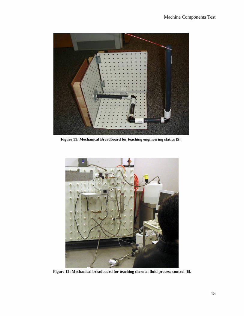
Figure 11: Mechanical Breadboard for teaching engineering statics [5]. ................................................... 15
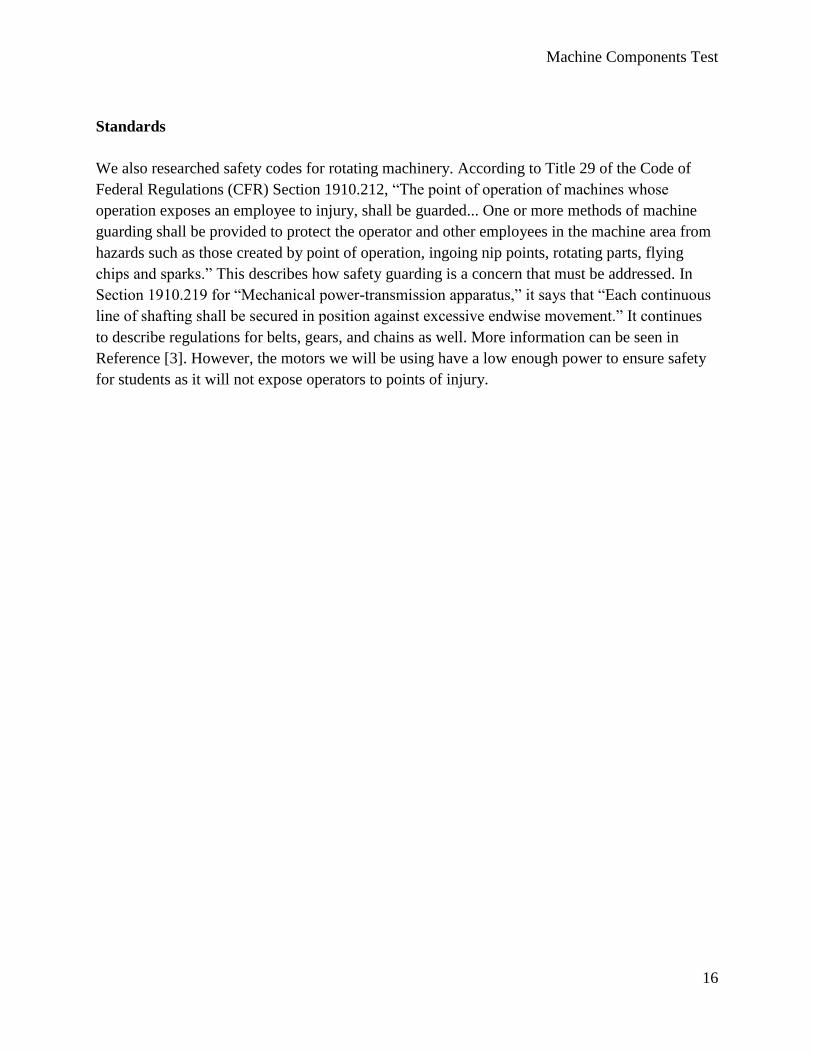
Figure 12: Mechanical breadboard for teaching thermal fluid process control [6]. .................................... 15
Figure 13: Concept model of the mechanical breadboard. ......................................................................... 21
Figure 14: The mechanical components found in a power drill. [7]. .......................................................... 21
Figure 15: Google Sketchup design of a chain system [8]. ......................................................................... 22
Figure 16: Example of components that can be used in the gear section of the lab [9]. ............................. 23
Figure 17: Tool diagram for a Makita 6406 power drill [10]. .................................................................... 23
Figure 18: Kinetic sculpture powered by human crank power [11]. ........................................................... 24
Figure 19: Mechanical Rube Goldberg machine used to open and pour wine [12]. ................................... 25
Figure 20: Preliminary 3D model of the chosen concept, the mechanical breadboard ............................... 26
Figure 21: Preliminary component sub-assemblies of mechanical breadboard .......................................... 27
Figure 22: Machine components test with pulley assembly. ...................................................................... 28
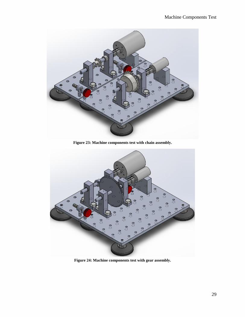
Figure 23: Machine components test with chain assembly. ........................................................................ 29
Figure 24: Machine components test with gear assembly. ......................................................................... 29
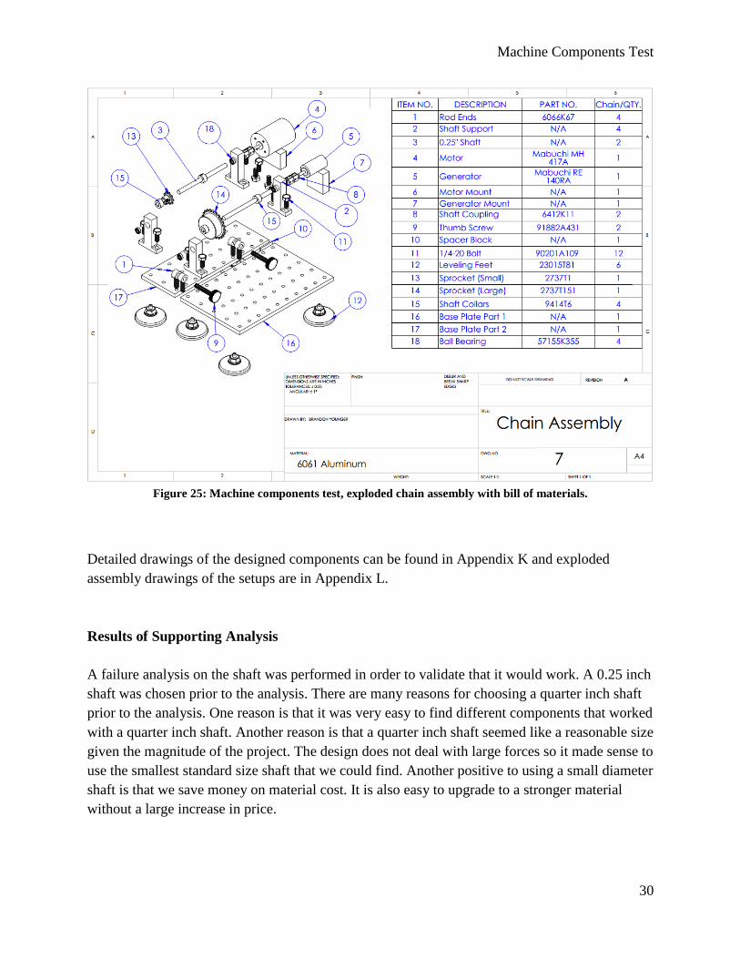
Figure 25: Machine components test, exploded chain assembly with bill of materials. ............................. 30
Figure 26: Attached sticker for safe use [13]. ............................................................................................. 32
Figure 27: This is the CNC that Brandon used to make the parts. .............................................................. 39
Figure 28: This is a picture of the spacer being made in the mill. .............................................................. 40
Figure 29: Temporary shaft couplings were made using delrin plastic on the lathe. .................................. 41
Figure 30: This is a photo of the complete prototype spur gear assembly. ................................................. 42
Figure 31: Picture of the chain and sprocket assembly ............................................................................... 43
Figure 32: This is the completed belt and pulley assembly. Note that temporary shaft couplings are shown
in this picture. Also not the configuration of the motors. ........................................................................... 44
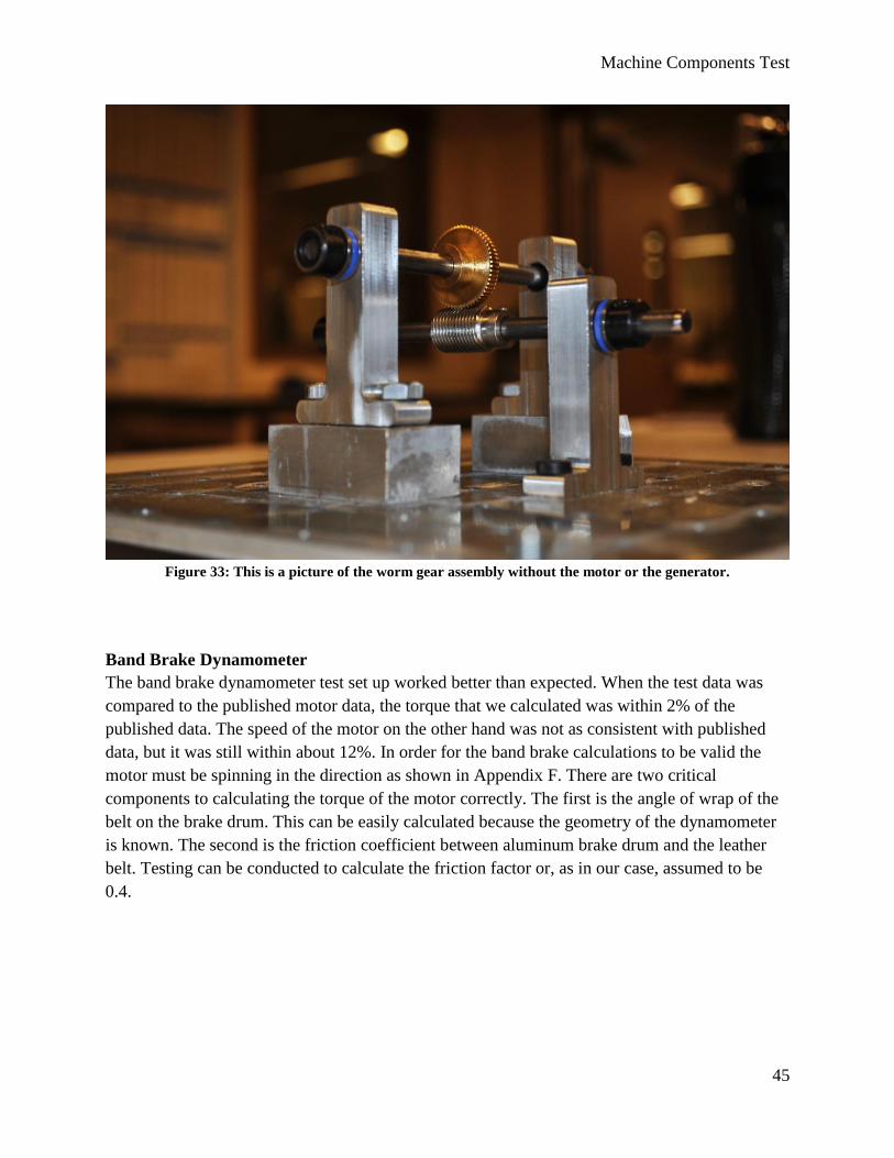
Figure 33: This is a picture of the worm gear assembly without the motor or the generator. .................... 45
Figure 34: This is a photo of the band brake dynamometer configuration without a hanging weight. ....... 46
Machine Components Test
5
List of Tables
Table 1: Machine Components Testing project formal engineering requirements. .................................... 18
Table 2: Results of analysis. ....................................................................................................................... 31
Table 3: Severity rating. .............................................................................................................................. 32
Table 4: Occurrence rating. ......................................................................................................................... 33
Table 5: Bill of materials cost analysis. ...................................................................................................... 36
Table 6: Vendor contact information .......................................................................................................... 37
Table 7: Total costs ..................................................................................................................................... 37
Machine Components Test
6
Abstract
To enhance California Polytechnic State University’s Mechanical Engineering program, Dr. Peter
Schuster has sponsored Brandon Younger, Lauren Romero, and Carlos Padilla to design and develop
a new lab for students in the Intermediate Design class to test real mechanical components. This
report discusses the background and ideation process that led to the development of the Educational
Mechanical Breadboard for Transmission System Components (Machine Components Test).
Additionally, detailed drawings, 3D modeling, testing plans, and analysis are included to show how
the Machine Components Test design will work and be validated.
Machine Components Test
7
Chapter 1: Introduction
Currently, intermediate design students in California Polytechnic State University’s (Cal Poly)
Mechanical Engineering department are in need of more hands on experience with real life
mechanical components. The current ME329 curriculum is missing a critical component.
Students need something that can clearly demonstrate to them what different mechanical
components can do, how they influence each other, and how they influence the system as a
whole. The goal of this addition to the curriculum is to help the students learn the material
presented in class. Cal Poly has a strong “learn by doing” philosophy so it is important that a
more hands on experience is provided in the intermediate design curriculum.
Dr. Schuster saw the need for a hands on interactive lab that would bridge the gap between the
material presented in class and the real world. We were assigned to the task of designing
something that would meet the need for ME329 students with Dr, Schuster as our sponsor.
Ideally the project would be funded by CP Connect with a budget of $2,000. CP Connect is a
program that allows students the opportunity to collaborate on interdisciplinary projects by
providing funding and resources. If we are denied funding by CP Connect, $1,000 will be
allocated by the Mechanical Engineering department to start a design project that will fill the
void in the intermediate design curriculum.
The goal for the project is to give intermediate design students the opportunity to obtain a better
understanding of how different components influence machine performance including shafts,
belts, chains, gears, and bearings. The purpose of this project is to design a mechanism that will
lead intermediate design students to gain the understanding required to become successful
engineers. The mechanism will allow students to measure motor performance curves, contain
real mechanical components, allow students to experiment with the configuration of the power
transmission system, and also to observe how changing different components can affect the
system performance. These are some of the requirements that the final design for this project will
meet. Additional requirements are discussed in the objective section.
Machine Components Test
8
Chapter 2: Background
The ME329 curriculum involves learning how common mechanical components used in real
mechanical systems work. The course introduces the following components: motors, gears, belts,
chains, shafts, bearings, brakes, fasteners, and springs. The students review how each component
works to get an idea of how to choose components for specific design criteria. Part of the reason
for implementing this lab is to help give students a more intuitive feel about how different
components affect a system. This is important for engineers because it allows the engineer to
have a general idea of how a system is going to perform before a formal analysis is conducted.
Because labs are usually only three hours long, not all the concepts covered in ME329 can be
demonstrated. Some concepts that are ruled out due the time constraint are fatigue, wear, and
corrosion. These aspects of design simply take too long to demonstrate. Concepts that can be
demonstrated in a three hour lab include: gear positioning effect on performance, motor
performance analysis, deflection in shafts, component failure mechanisms (like slipping belts, or
a chain skipping a tooth), lubrication effects on bearings, shaft critical speed, and the effect of
different components on the system efficiency.
In Cal Poly’s intermediate design class, the only experience students have with real mechanical
components is what Dr. Schuster calls the “machine teardown”. In the “machine teardown”,
students have the opportunity to take apart old hand power tools to examine how they work. The
students are also assigned a design
project where they make a prototype of
their design using LEGO Technics as
seen in Figure 1. The core of the
student’s design project is usually to
design a power transmission system
using what they learned in class. The
LEGOs allow the students to produce
their designs using plastic gears and
plastic shafts, but Dr. Schuster is
concerned that students do not really
understand how different components
influence the system. He is concerned
that when students work with small scale plastic parts they fail to make the connection between
the system and its components. In other words, because these products are made out of plastic
and are small scale models, they are an unrealistic comparison to common components used in
industry.
Figure 1: Lego Model from an intermediate design class.
Machine Components Test
9
Existing Labs
Initial research has revealed that there are no comparable products on the market. We researched
the Cal Poly library database, Google, and the ASEE site for projects that might be similar to
what we are trying to accomplish. Our problem with finding something similar to what Dr.
Schuster wants is not that no such project exists, but that many of the universities and
educational institutions have not published details of their machine design labs. Another
possibility is that different instructors of intermediate design have different ways of managing
the course that include different projects or labs to explain component interaction.
Although a product that matches the requirements of our project was not found, some examples
of what other universities are doing to educate their engineering students were found. Central
Washington University has developed two labs for their machine design students. The first is the
examination of a three-speed manual transmission with part of the casing removed as shown in
Figure 2. The students get a general introduction about how the transmission works. Then they
are asked to observe the mechanism and determine the input and output ratios by counting the
teeth on the gears. The second lab is an examination of the Ford Model T planetary transmission
seen in Figure 3. Again the students are introduced to the transmission and given some
background information. They then have to analyze the planetary transmission using the
analytical skills they learned in their dynamics course. More information about these labs can be
found by looking at Reference [1].
Figure 2: The Ford three-speed manual transmission used in the Central Washington University lab.
Machine Components Test
10
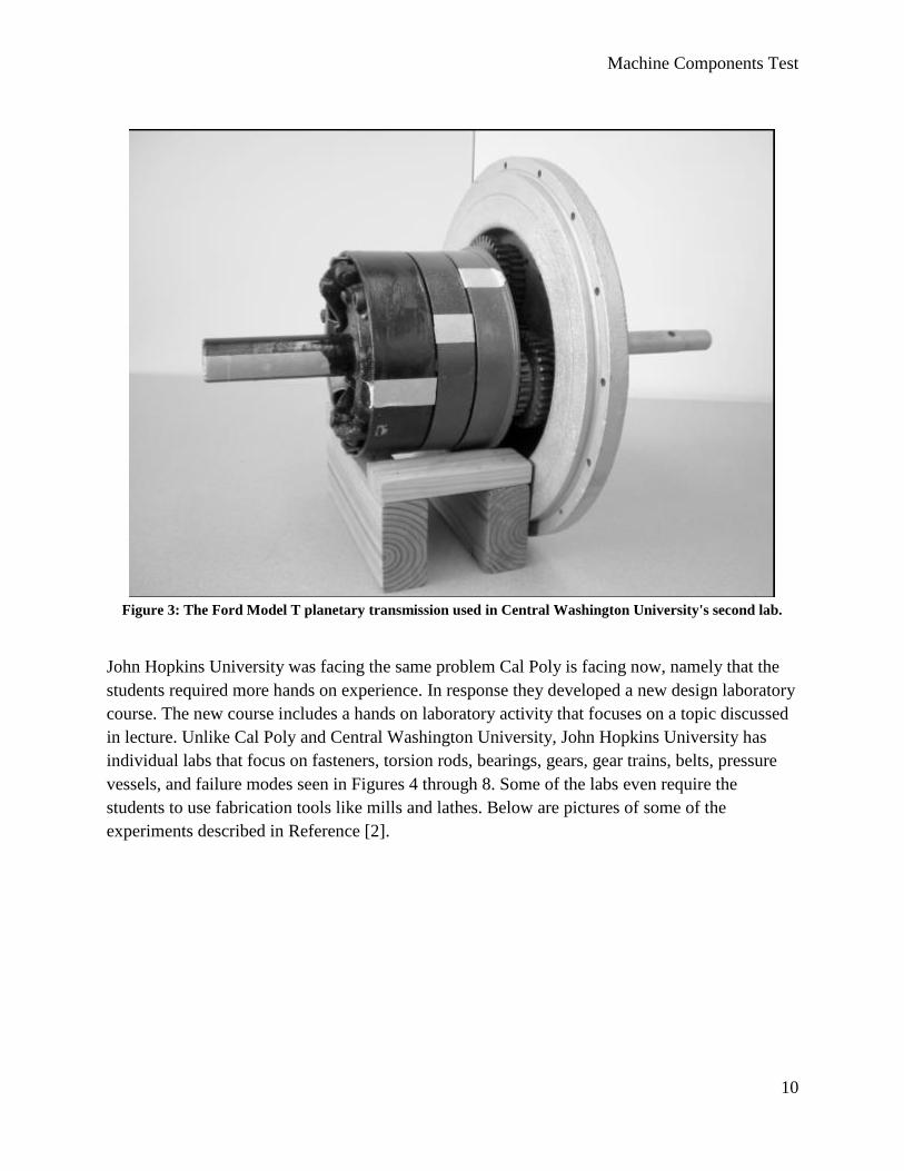
Figure 3: The Ford Model T planetary transmission used in Central Washington University's second lab.
John Hopkins University was facing the same problem Cal Poly is facing now, namely that the
students required more hands on experience. In response they developed a new design laboratory
course. The new course includes a hands on laboratory activity that focuses on a topic discussed
in lecture. Unlike Cal Poly and Central Washington University, John Hopkins University has
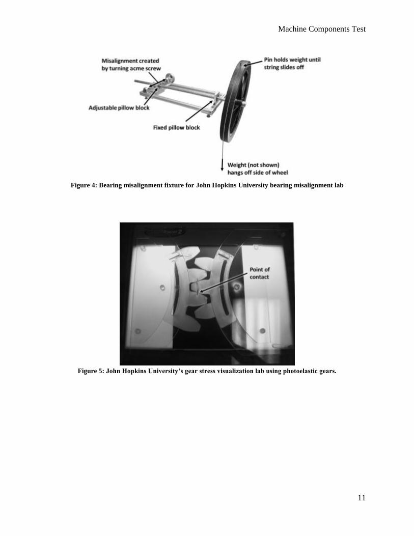
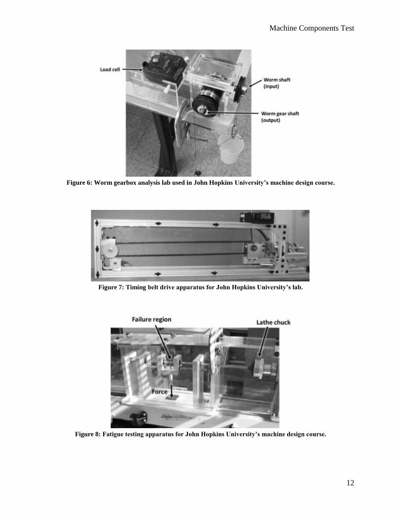
individual labs that focus on fasteners, torsion rods, bearings, gears, gear trains, belts, pressure
vessels, and failure modes seen in Figures 4 through 8. Some of the labs even require the
students to use fabrication tools like mills and lathes. Below are pictures of some of the
experiments described in Reference [2].
Machine Components Test
11
Figure 4: Bearing misalignment fixture for John Hopkins University bearing misalignment lab
Figure 5: John Hopkins University’s gear stress visualization lab using photoelastic gears.
Machine Components Test
12
Figure 6: Worm gearbox analysis lab used in John Hopkins University’s machine design course.
Figure 7: Timing belt drive apparatus for John Hopkins University’s lab.
Figure 8: Fatigue testing apparatus for John Hopkins University’s machine design course.

Machine Components Test
13
State of the Art: Mechanical Breadboards
As stated above, an initial search did not reveal any products that met the requirements for the
design. The problem was that a refined search term was needed for the information to surface.
After some brainstorming, an analogy between what we were trying to accomplish and the
concept of a breadboard used in the Electrical Engineering department was made. This led to a
new search term, the “mechanical breadboard”. A mechanical breadboard uses the same concept
of an electrical breadboard. The difference is that instead of the ability to create different circuits;
the mechanical breadboard allows the use to create different mechanical power transmission
systems.
Mechanical breadboarding is a concept that has been around since the 1950’s. It is not a new
concept, but has not yet been developed to improve student understanding in mechanical
systems. A search revealed only two companies that make a mechanical breadboard kits. Pic
Design and V.M. Berg both make a mechanical breadboard kit that you can buy as shown in
Figures 9 and 10 below. The downside to these products is cost. They have a price range of $500
for a basic system to $4,000 for a complete kit [4]. These products involve precise components
and are designed more to prototype concepts rather than demonstrate mechanical principles.
According to a patent search performed by James Mikes, author of The Analysis and
Development of a Mechanical Breadboard Structure, no patents exist on mechanical
breadboards.
Figure 9: V.M Berg mechanical breadboard design [4]
Machine Components Test
14
Figure 10: Pic Design mechanical breadboard example [4]
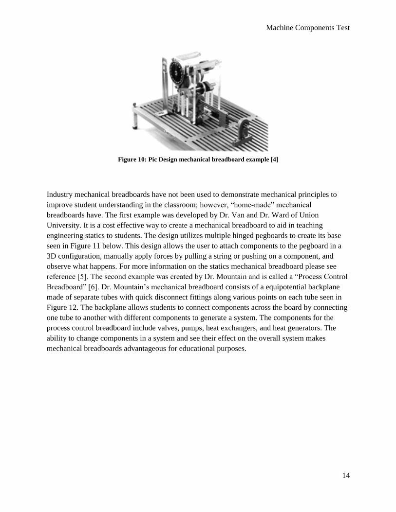
Industry mechanical breadboards have not been used to demonstrate mechanical principles to
improve student understanding in the classroom; however, “home-made” mechanical
breadboards have. The first example was developed by Dr. Van and Dr. Ward of Union
University. It is a cost effective way to create a mechanical breadboard to aid in teaching
engineering statics to students. The design utilizes multiple hinged pegboards to create its base
seen in Figure 11 below. This design allows the user to attach components to the pegboard in a
3D configuration, manually apply forces by pulling a string or pushing on a component, and
observe what happens. For more information on the statics mechanical breadboard please see
reference [5]. The second example was created by Dr. Mountain and is called a “Process Control
Breadboard” [6]. Dr. Mountain’s mechanical breadboard consists of a equipotential backplane
made of separate tubes with quick disconnect fittings along various points on each tube seen in
Figure 12. The backplane allows students to connect components across the board by connecting
one tube to another with different components to generate a system. The components for the
process control breadboard include valves, pumps, heat exchangers, and heat generators. The
ability to change components in a system and see their effect on the overall system makes
mechanical breadboards advantageous for educational purposes.
Machine Components Test
15
Figure 12: Mechanical breadboard for teaching thermal fluid process control [6].
Figure 11: Mechanical Breadboard for teaching engineering statics [5].
Machine Components Test
16
Standards
We also researched safety codes for rotating machinery. According to Title 29 of the Code of
Federal Regulations (CFR) Section 1910.212, “The point of operation of machines whose
operation exposes an employee to injury, shall be guarded... One or more methods of machine
guarding shall be provided to protect the operator and other employees in the machine area from
hazards such as those created by point of operation, ingoing nip points, rotating parts, flying
chips and sparks.” This describes how safety guarding is a concern that must be addressed. In
Section 1910.219 for “Mechanical power-transmission apparatus,” it says that “Each continuous
line of shafting shall be secured in position against excessive endwise movement.” It continues
to describe regulations for belts, gears, and chains as well. More information can be seen in
Reference [3]. However, the motors we will be using have a low enough power to ensure safety
for students as it will not expose operators to points of injury.

Machine Components Test
17
Chapter 3: Design Development
Design Objectives
Our overall objective is to create a machine containing a power transmission system with real
mechanical components that is configurable, allows for power loss measurements, and allows for
motor analysis to help further the knowledge of intermediate design students in the Mechanical
Engineering department.
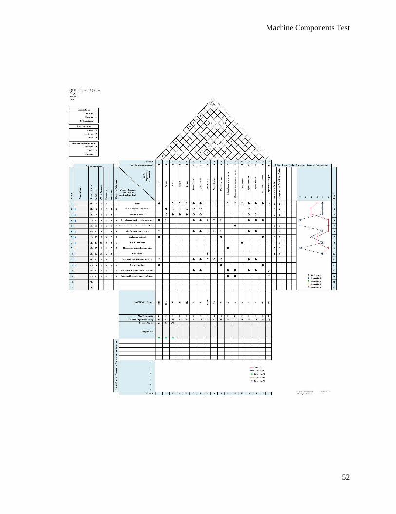
In an effort to meet all our customer’s interests we used quality function deployment to develop a
house of quality, shown and explained in Appendix B, to identify all customer requirements. We
then used the results of our house of quality to generate a table of the engineering requirements
for this product. Additionally, risk is included with three levels of importance, high (H), medium
(M), and low (L). The compliance will be assessed by methods of analysis (A), test (T),
similarity to existing designs (S), and/or inspection (I) as seen in the Table 1 below.
This product will be handled by students and teachers who need to move the product across the
room. Therefore, a reasonable weight limit of 20 pounds is required. Additionally, the size of the
product must fit within a 3 feet wide by 2 feet deep by 1 foot ’X2’X1’ shelf, and thus the
dimensions are limited as well. Our product may be reproduced for future classes. This means
the machining and assembly time for reproducibility must be reasonable, 12 and 3 hours
respectively.
Dr. Shuster would like multiple breadboards to be used in class so that a team of two or three
students can work on an individual board. The cost must then be low, around $300 a piece, to be
in the Mechanical Engineering Department’s budget.
The purpose of the project is for students to visually see the difference between real mechanical
components, therefore a minimum of five types of components: chains, belts, gears, shafts, and
bearings, is our goal. Additionally, at least two types of these five components will be included
to see how different materials affect power loss. We hope to buy as many different components
as possible, but cost will be the limiting factor. These components will all be bought, so we aim
for 90% of our product to include standard parts.
Labs are three hours long, so we need to make a product that can be set up relatively quickly, ten
minutes at most. There also must be no pinch points to allow for the safety of students. The main
measurable parts of our project will be motor characteristics and transmission efficiency. We will
provide the tools and instructions on how students will be able to do this. The will then be able to
compare these measured values to different transmission set ups (at minimum 4).
Machine Components Test
18
Finally, we plan to survey and quiz the students after they use our product to see if it enhanced
their learning. The student survey involves asking students if they thought our new lab was
helpful in their understanding of mechanical components, what they feel was missing or difficult,
and if they think the lab should be offered to future design students. The quiz would assess
student understanding of mechanical components before and after this product was used to see if
there was any improvement.
Table 1: Machine Components Testing project formal engineering requirements.
Spec. # Parameter Description Requirement or Target
(units)
Tolerance Risk Compliance
1 Weight 20 lb max H A,T
2 Size 3’x2’x1’ max H A,T
3 Machining Time 12 hr max L T
4 Assembly Time 3 hr max L T
5 Production Cost $300 max M A,T
6 Real Mechanical
Components
5 different types
(chains, belts, gears,
bearings, shafts)
min L I
7 Number of gears, chains,
belts, and bearings
2 each min M I
8 % of Standard Parts 90% min L A
9 Setup Time 10 min max M T
10 Measurable Motor
Characteristics
3 min M A, T
11 Measurable Power
Transmission Efficiency
2 min M A, T
12 Configurable Components 4 unique configurations min M A,T,I
13 Student Surveys and
Quizes
15% improvement min M I

Machine Components Test
19
Machine Components Test
20
Preliminary Designs
After gaining a strong sense of the problem statement and objectives, we developed a list of
functions our product must do. Appendix B displays a QFD chart that was used to compare
functions, engineering requirements, users, and existing products. These functions were used
when analyzing our different ideas. Once we knew how our product would function, we started
formulating ideas. Some techniques used were brainstorming, brainwriting, and SCAMPER.
Brainstorming is saying out loud all ideas we could come up with and writing them down,
whereas brainwriting is writing down ideas and passing them to another group member to
expand on them. Finally, SCAMPER is taking ideas and adjusting them or combining them to
come up with new ideas.
Through the design ideation techniques, we developed various ideas to help students better
understand mechanical components. Our concepts satisfy specifications because they give
students experiences with actual mechanical components in different ways. Each method tries to
give students a learning opportunity about gears, belts, chains, and motors. Some ideas are more
complex than others and might require more than one lab period to complete. The following are
the preliminary ideas we came up with:
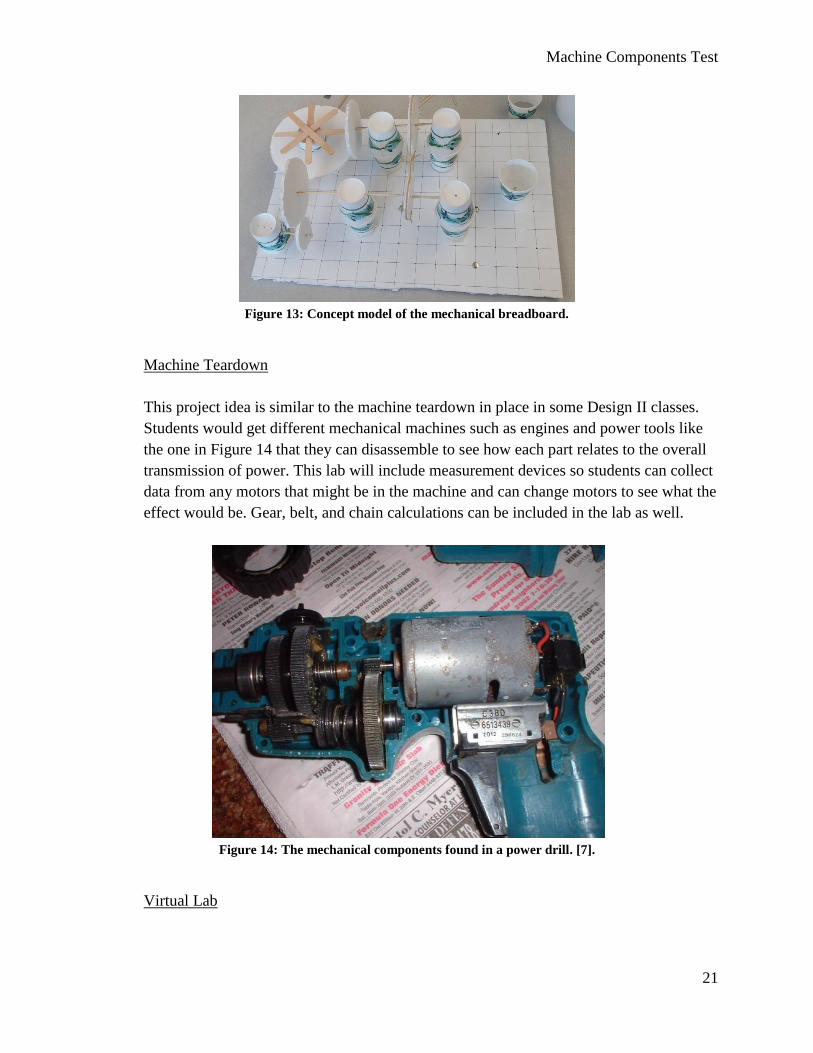
Mechanical Breadboard
The mechanical breadboard lab involves a breadboard meant for mechanical components.
It is larger than the electrical breadboard students are used to using. Parts are
interchangeable on the board to allow for a large range of different transmission systems.
Dynamometers and multimeters would be attached throughout the system to record data.
Students can calculate power loss and directly observe gear slipping and beam bending
with the tangible set up. Power would be supplied by a motor and students would transfer
power to a generator through the use of real gears, pulleys, belts, chains, shafts, and
bearings. Figure 13 below shows a concept model of this design made from foam board,
paper cubs and wood to show this design.
Machine Components Test
21
Figure 13: Concept model of the mechanical breadboard.
Machine Teardown
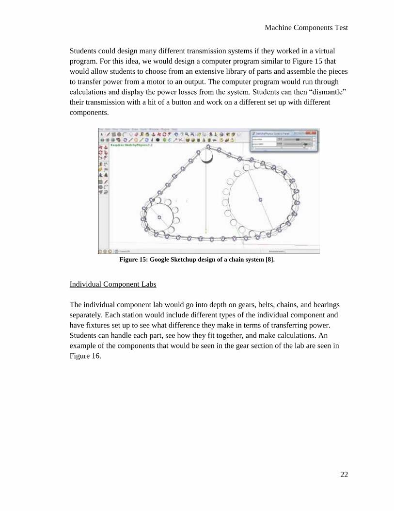
This project idea is similar to the machine teardown in place in some Design II classes.
Students would get different mechanical machines such as engines and power tools like
the one in Figure 14 that they can disassemble to see how each part relates to the overall
transmission of power. This lab will include measurement devices so students can collect
data from any motors that might be in the machine and can change motors to see what the
effect would be. Gear, belt, and chain calculations can be included in the lab as well.
Figure 14: The mechanical components found in a power drill. [7].
Virtual Lab
Machine Components Test
22
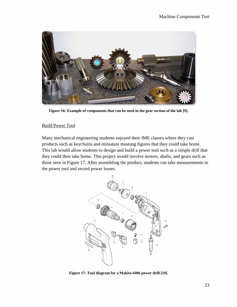
Students could design many different transmission systems if they worked in a virtual
program. For this idea, we would design a computer program similar to Figure 15 that
would allow students to choose from an extensive library of parts and assemble the pieces
to transfer power from a motor to an output. The computer program would run through
calculations and display the power losses from the system. Students can then “dismantle”
their transmission with a hit of a button and work on a different set up with different
components.
Figure 15: Google Sketchup design of a chain system [8].
Individual Component Labs
The individual component lab would go into depth on gears, belts, chains, and bearings
separately. Each station would include different types of the individual component and
have fixtures set up to see what difference they make in terms of transferring power.
Students can handle each part, see how they fit together, and make calculations. An
example of the components that would be seen in the gear section of the lab are seen in
Figure 16.
Machine Components Test
23
Figure 16: Example of components that can be used in the gear section of the lab [9].
Build Power Tool
Many mechanical engineering students enjoyed their IME classes where they cast
products such as keychains and miniature mustang figures that they could take home.
This lab would allow students to design and build a power tool such as a simple drill that
they could then take home. This project would involve motors, shafts, and gears such as
those seen in Figure 17. After assembling the product, students can take measurements in
the power tool and record power losses.
Figure 17: Tool diagram for a Makita 6406 power drill [10].
Machine Components Test
24
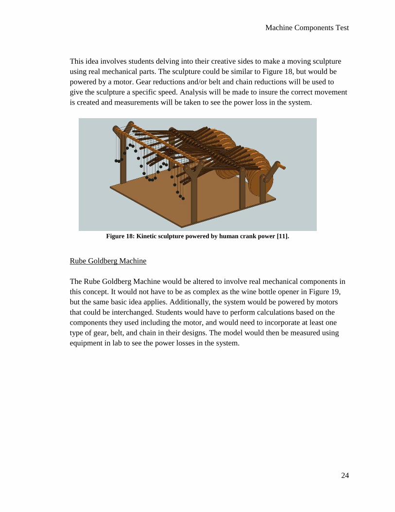
This idea involves students delving into their creative sides to make a moving sculpture
using real mechanical parts. The sculpture could be similar to Figure 18, but would be
powered by a motor. Gear reductions and/or belt and chain reductions will be used to
give the sculpture a specific speed. Analysis will be made to insure the correct movement
is created and measurements will be taken to see the power loss in the system.
Figure 18: Kinetic sculpture powered by human crank power [11].
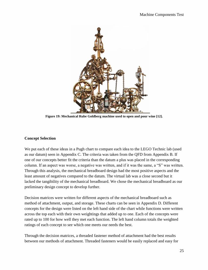
Rube Goldberg Machine
The Rube Goldberg Machine would be altered to involve real mechanical components in
this concept. It would not have to be as complex as the wine bottle opener in Figure 19,
but the same basic idea applies. Additionally, the system would be powered by motors
that could be interchanged. Students would have to perform calculations based on the
components they used including the motor, and would need to incorporate at least one
type of gear, belt, and chain in their designs. The model would then be measured using
equipment in lab to see the power losses in the system.
Machine Components Test
25
Figure 19: Mechanical Rube Goldberg machine used to open and pour wine [12].
Concept Selection
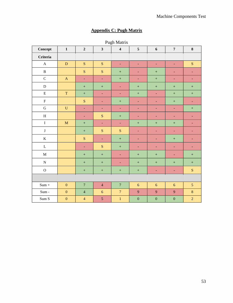
We put each of these ideas in a Pugh chart to compare each idea to the LEGO Technic lab (used
as our datum) seen in Appendix C. The criteria was taken from the QFD from Appendix B. If
one of our concepts better fit the criteria than the datum a plus was placed in the corresponding
column. If an aspect was worse, a negative was written, and if it was the same, a “S” was written.
Through this analysis, the mechanical breadboard design had the most positive aspects and the
least amount of negatives compared to the datum. The virtual lab was a close second but it
lacked the tangibility of the mechanical breadboard. We chose the mechanical breadboard as our
preliminary design concept to develop further.
Decision matrices were written for different aspects of the mechanical breadboard such as
method of attachment, output, and storage. These charts can be seen in Appendix D. Different
concepts for the design were listed on the left hand side of the chart while functions were written
across the top each with their own weightings that added up to one. Each of the concepts were
rated up to 100 for how well they met each function. The left hand column totals the weighted
ratings of each concept to see which one meets our needs the best.
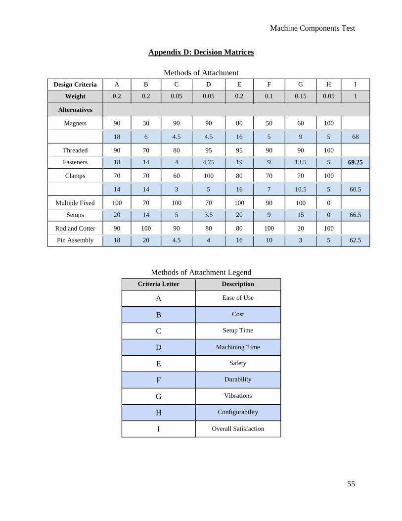
Through the decision matrices, a threaded fastener method of attachment had the best results
between our methods of attachment. Threaded fasteners would be easily replaced and easy for
Machine Components Test
26
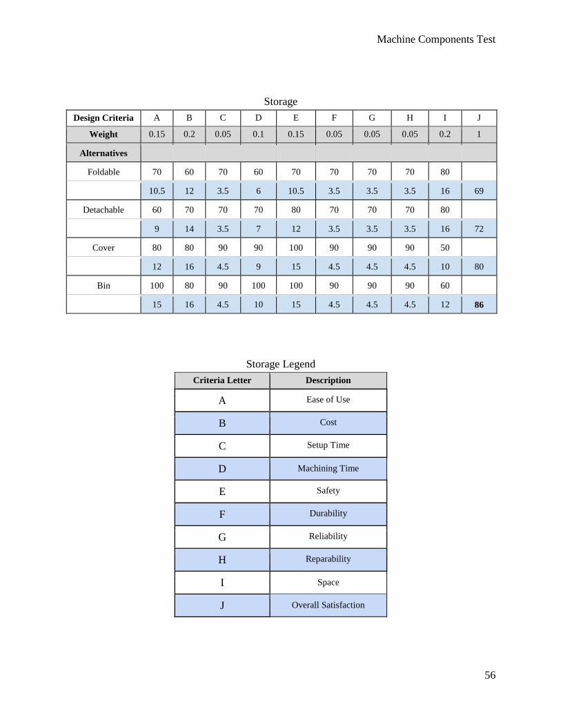
students to use to move components around the base. Additionally, the storage method that
proved best was a bin. This would cheaply hold all the mechanical components and condense
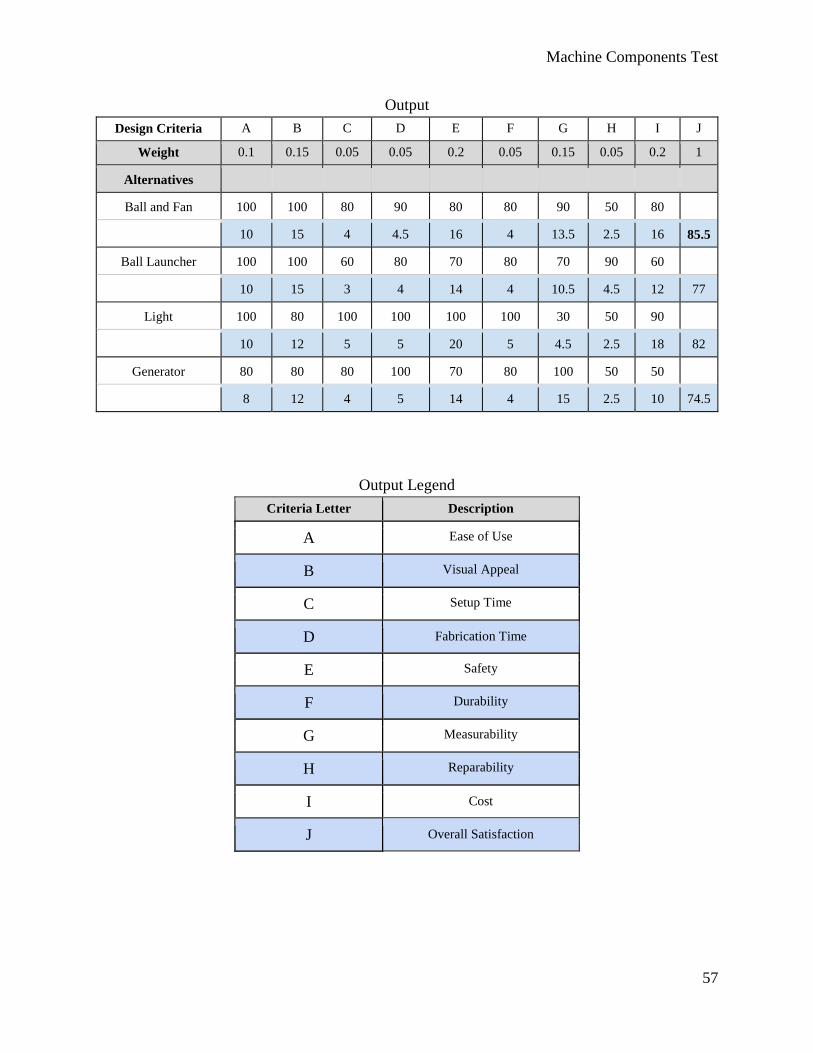
them to better fit in the designated cabinets. Lastly, the output chart showed that a fan and ball
output would be a good visual addition to the lab and add a fluid mechanic aspect. Power output
from the transmission system would power a generator that would then power a fan encased in a
clear tube. Air from the fan would be concentrated to lift a lightweight ball into the air.
Depending on the power losses of the system, the ball would move higher or lower.
To justify our selected concept, analysis was done on the amount of energy it would take to lift a
Styrofoam ball, and the stress that power would cause in the system on the board, fasteners, and
other components. This analysis can be seen in Appendix F, “Calculations.” The results of this
analysis lead us to our desired sizes of components to ensure a safe mechanism.
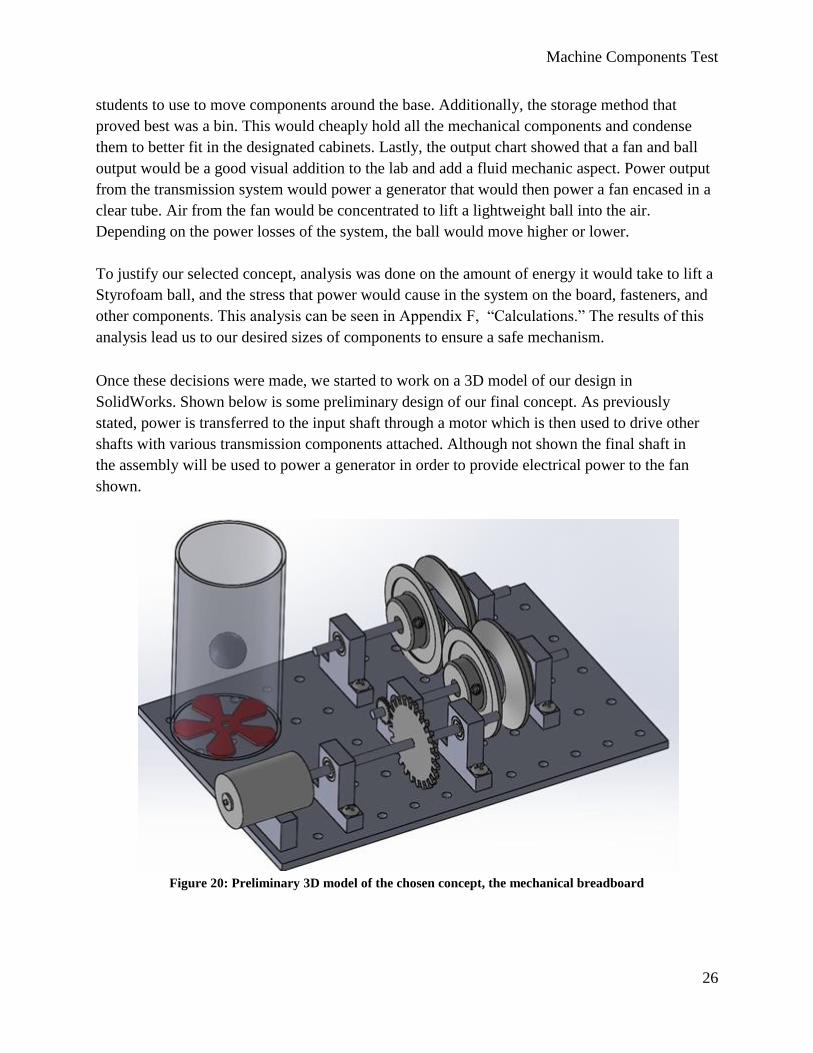
Once these decisions were made, we started to work on a 3D model of our design in
SolidWorks. Shown below is some preliminary design of our final concept. As previously
stated, power is transferred to the input shaft through a motor which is then used to drive other
shafts with various transmission components attached. Although not shown the final shaft in
the assembly will be used to power a generator in order to provide electrical power to the fan
shown.
Figure 20: Preliminary 3D model of the chosen concept, the mechanical breadboard
Machine Components Test
27
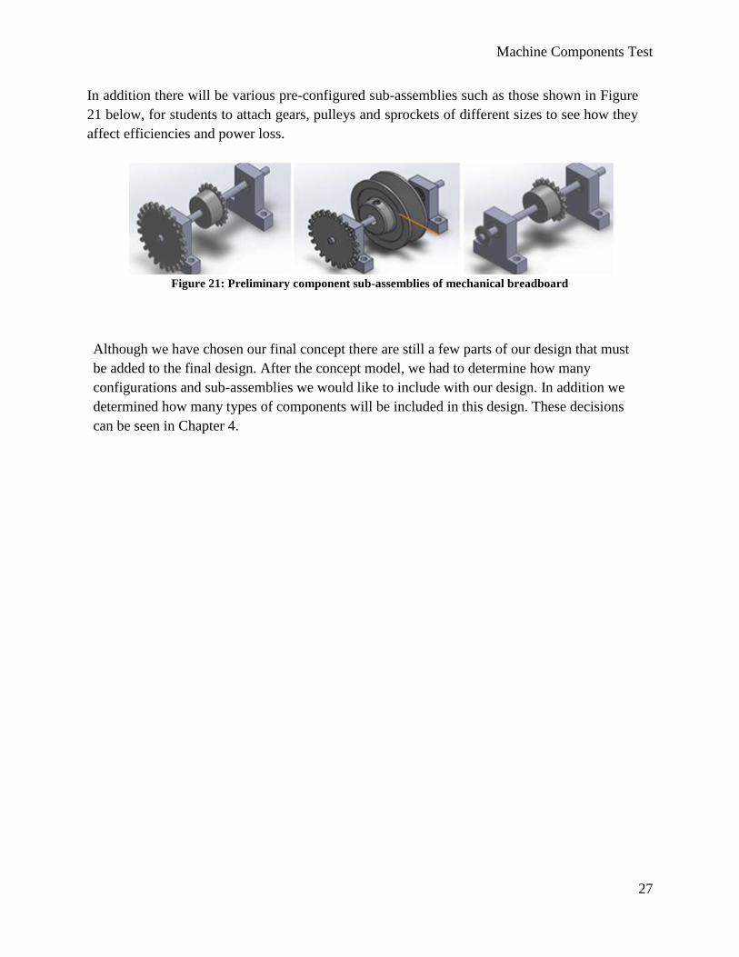
In addition there will be various pre-configured sub-assemblies such as those shown in Figure
21 below, for students to attach gears, pulleys and sprockets of different sizes to see how they
affect efficiencies and power loss.
Figure 21: Preliminary component sub-assemblies of mechanical breadboard
Although we have chosen our final concept there are still a few parts of our design that must
be added to the final design. After the concept model, we had to determine how many
configurations and sub-assemblies we would like to include with our design. In addition we
determined how many types of components will be included in this design. These decisions
can be seen in Chapter 4.
Machine Components Test
28
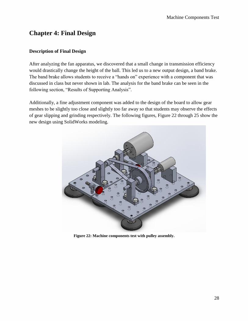
Chapter 4: Final Design
Description of Final Design
After analyzing the fan apparatus, we discovered that a small change in transmission efficiency
would drastically change the height of the ball. This led us to a new output design, a band brake.
The band brake allows students to receive a “hands on” experience with a component that was
discussed in class but never shown in lab. The analysis for the band brake can be seen in the
following section, “Results of Supporting Analysis”.
Additionally, a fine adjustment component was added to the design of the board to allow gear
meshes to be slightly too close and slightly too far away so that students may observe the effects
of gear slipping and grinding respectively. The following figures, Figure 22 through 25 show the
new design using SolidWorks modeling.
Figure 22: Machine components test with pulley assembly.
Machine Components Test
29
Figure 23: Machine components test with chain assembly.
Figure 24: Machine components test with gear assembly.
Machine Components Test
30
Figure 25: Machine components test, exploded chain assembly with bill of materials.
Detailed drawings of the designed components can be found in Appendix K and exploded
assembly drawings of the setups are in Appendix L.
Results of Supporting Analysis
A failure analysis on the shaft was performed in order to validate that it would work. A 0.25 inch
shaft was chosen prior to the analysis. There are many reasons for choosing a quarter inch shaft
prior to the analysis. One reason is that it was very easy to find different components that worked
with a quarter inch shaft. Another reason is that a quarter inch shaft seemed like a reasonable size
given the magnitude of the project. The design does not deal with large forces so it made sense to
use the smallest standard size shaft that we could find. Another positive to using a small diameter
shaft is that we save money on material cost. It is also easy to upgrade to a stronger material
without a large increase in price.
Machine Components Test
31
In order to perform the analysis we had to assume a stall torque. Dr. Schuster was able to provide
some sample motors for testing, from which a stall torque of 0.2 Nm was assumed to be
reasonable for the analysis. For the analysis the shaft was chosen to be made out of 1018 steel.
The failure analysis was performed on both the spur and worm gear subassemblies. Since both
gear assemblies had a small pitch diameter of 0.5 inches the reacting forces would be greater
than the other assemblies. The detailed analysis can be found in Appendix I. A summary of the
results can be found in Table 2. The results of the analysis suggest that a 0.25 inch diameter shaft
is more than strong enough to handle the assumed stall torque of the motor.
Table 2: Results of analysis.
Shaft Components Von Mises Stress
(Mpa)
Safety Factor Max Deflection
(in)
Spur Gear 20.26 15.3 0.00032
Worm Gear 31.8 9.74 0.00137
Safety Considerations
According to the United States Department of Labor, Occupational Safety & Health
Administration Section 1910.212(a)(3)(ii), for guarding rotating machinery, “The point of
operation of machines whose operation exposes an employee to injury, shall be guarded.” ;
therefore, we are considering making a polycarbonate casing that would cover the board and be
secured with magnets. Additionally, there are precautions students must be made aware of.
Appendix J shows a hazard checklist to determine where safety may be a concern.
Students will be our target user for this product, therefore, safety is a major concern. To address
safety, we will include a safety list in the lab instructions. This list will tell students that long hair
must pulled back and long sleeves must be rolled back to prevent hair and clothing from getting
caught in the moving components. The following shows what may be included in the beginning
of the lab:
Safety Checklist
1. Long hair must be pulled back.
2. Long sleeves must be rolled up.
3. Safety glasses must be worn at all times.
4. Turn motor off, and wait until all components stop before rearranging components.
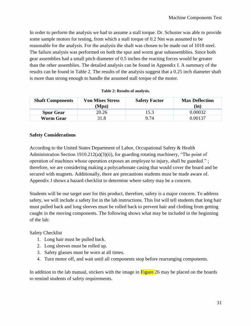
In addition to the lab manual, stickers with the image in Figure 26 may be placed on the boards
to remind students of safety requirements.
Machine Components Test
32
Figure 26: Attached sticker for safe use [13].
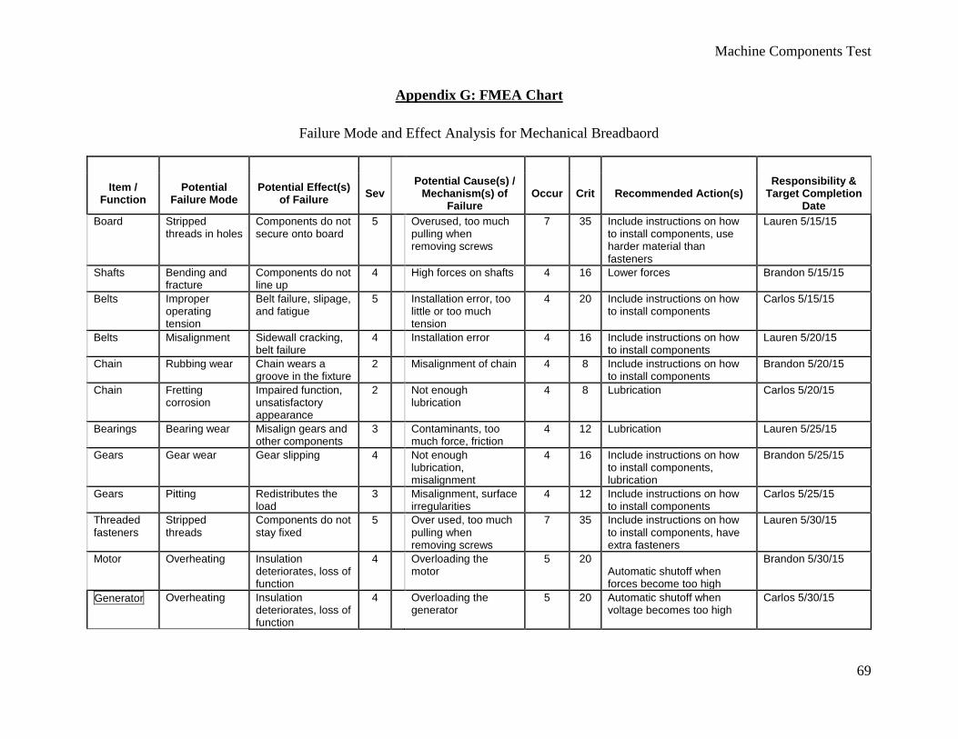
Additionally, to consider the safety of the product design, a Failure Mode Effect Analysis
(FMEA) chart was created. This can be found in Appendix G. With the FMEA, we found all the
potential failure modes of our design and their effects and consequences. Afterwards, we rated
the occurrence and criticality to determine what our main safety concerns will be. For ranking we
used the following scales seen in Tables 3 and 4.
Table 3: Severity rating.
Number Severity
1 Negligible (no discernible
effect)
4 Marginal (appearance or noise
issue, not functional)
7 Critical (degradation of primary
function)
10 Catastrophic (severe injury)
Machine Components Test
33
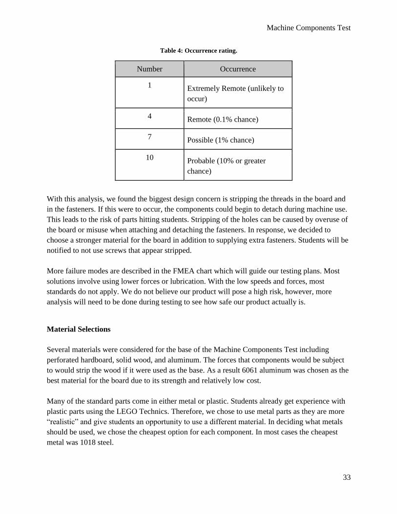
Table 4: Occurrence rating.
Number Occurrence
1 Extremely Remote (unlikely to
occur)
4 Remote (0.1% chance)
7 Possible (1% chance)
10 Probable (10% or greater
chance)
With this analysis, we found the biggest design concern is stripping the threads in the board and
in the fasteners. If this were to occur, the components could begin to detach during machine use.
This leads to the risk of parts hitting students. Stripping of the holes can be caused by overuse of
the board or misuse when attaching and detaching the fasteners. In response, we decided to
choose a stronger material for the board in addition to supplying extra fasteners. Students will be
notified to not use screws that appear stripped.
More failure modes are described in the FMEA chart which will guide our testing plans. Most
solutions involve using lower forces or lubrication. With the low speeds and forces, most
standards do not apply. We do not believe our product will pose a high risk, however, more
analysis will need to be done during testing to see how safe our product actually is.
Material Selections
Several materials were considered for the base of the Machine Components Test including
perforated hardboard, solid wood, and aluminum. The forces that components would be subject
to would strip the wood if it were used as the base. As a result 6061 aluminum was chosen as the
best material for the board due to its strength and relatively low cost.
Many of the standard parts come in either metal or plastic. Students already get experience with
plastic parts using the LEGO Technics. Therefore, we chose to use metal parts as they are more
“realistic” and give students an opportunity to use a different material. In deciding what metals
should be used, we chose the cheapest option for each component. In most cases the cheapest
metal was 1018 steel.
Machine Components Test
34
The shaft supports, and motor mounts will be made 6061 aluminum because it is light, relatively
cheap and will be strong enough to support the shafts and bearings.
Manufacturing
Our plan for construction is to buy all of the components and material from the appropriate
vendors listed in Table 5. We plan on ordering the parts May 8th, allowing two weeks for
delivery. The base plate will then be manufactured on the CNC machine in the Mustang '60
machine shop by Brandon Younger. This part of the manufacturing will take three hours and is
planned to be completed by May 15th.
Additionally, the shaft supports will also be CNC machined in the Mustang '60 machine shop.
We will start with standard rectangular stock and machine 12 housings by May 22. This process
should take up to six hours.
Once all of the components have arrived and parts have been made, assembly will be done based
on the assembly drawing in Appendix L at the Cal Poly Machine Shop. The tools needed will be
wrenches and a hydraulic press and the process will take one hour. We hope to finish this by
May 29th.
Maintenance and Repair
Maintenance for our product involves proper care of the components. This includes proper
storage in the provided bins. Components should be stored in a dry environment. Lubrication
may be used in the gearing to prevent overheating. Any fasteners with stripped threads must be
disposed of as they will risk student safety if used. Additional fasteners will be provided.
Students must read the lab manual for correct use of the product to ensure maximum product life.
Most of the Machine Components Test will be standard parts that can easily be purchased using
the information found in the bill of materials in the detailed drawings. If a component breaks or
is worn out, users may go to the website indicated in the references and search the part number.
Smaller parts such as the threaded fasteners and shaft supports will be the first to break or get
lost, therefore extra parts will be supplied.
The board and shaft supports are not standard parts, and will therefore be machined in house.
The dimensions for machining the board and the supports are included in this report. In addition
G-code for CNC machining this parts will be included in the final design report. If more boards
or shaft supports are desired, or existing pieces have failed, the manufacturing instructions can be
given to the shop techs in one of Cal Poly’s machine labs.
Machine Components Test
35
Cost Analysis
We will be doing the manufacturing and assembly ourselves, so the budget is mostly
concentrated in the materials. Mechanical components can be costly, especially in the smaller
quantities that we need (enough for one lab section). Originally our budget was $300 per
product; however, we plan to distribute more complex components that each lab section can
share. The greater variety of components, the more interesting and educational our product will
be. Therefore, the average cost of each product will be slightly higher than originally anticipated.
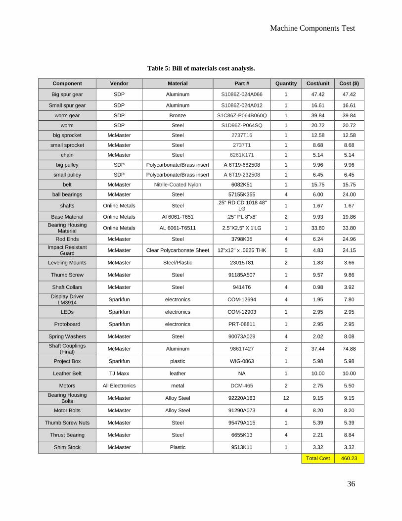
Additionally, some funds must be allocated to prototyping and testing. In Table 5 below, a
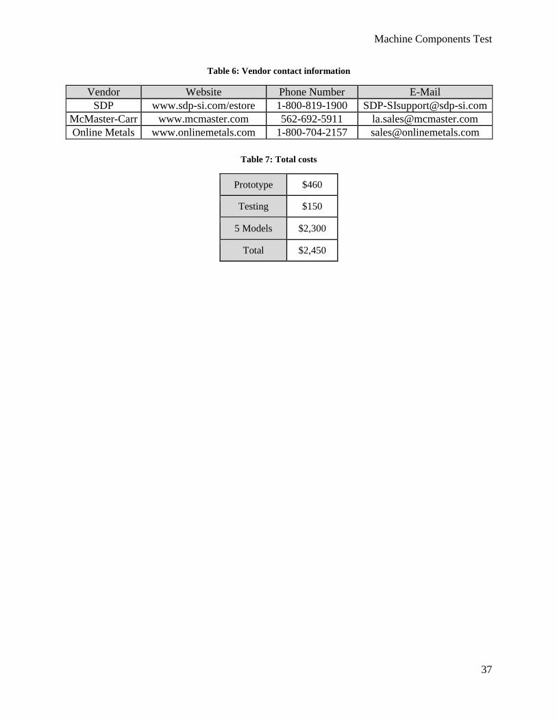
breakdown of the material costs is illustrated. Table 6 gives the contact information for each
vendor. Table 7 includes additional costs for the project.
Machine Components Test
36
Table 5: Bill of materials cost analysis.
Component Vendor Material Part # Quantity Cost/unit Cost ($)
Big spur gear SDP Aluminum S1086Z-024A066 1 47.42 47.42
Small spur gear SDP Aluminum S1086Z-024A012 1 16.61 16.61
worm gear SDP Bronze S1C86Z-P064B060Q 1 39.84 39.84
worm SDP Steel S1D96Z-P064SQ 1 20.72 20.72
big sprocket McMaster Steel 2737T16 1 12.58 12.58
small sprocket McMaster Steel 2737T1 1 8.68 8.68
chain McMaster Steel 6261K171 1 5.14 5.14
big pulley SDP Polycarbonate/Brass insert A 6T19-682508 1 9.96 9.96
small pulley SDP Polycarbonate/Brass insert A 6T19-232508 1 6.45 6.45
belt McMaster Nitrile-Coated Nylon 6082K51 1 15.75 15.75
ball bearings McMaster Steel 57155K355 4 6.00 24.00
shafts Online Metals Steel .25" RD CD 1018 48"
LG 1 1.67 1.67
Base Material Online Metals Al 6061-T651 .25" PL 8"x8" 2 9.93 19.86
Bearing Housing Material
Online Metals AL 6061-T6511 2.5"X2.5" X 1'LG 1 33.80 33.80
Rod Ends McMaster Steel 3798K35 4 6.24 24.96
Impact Resistant Guard
McMaster Clear Polycarbonate Sheet 12"x12" x .0625 THK 5 4.83 24.15
Leveling Mounts McMaster Steel/Plastic 23015T81 2 1.83 3.66
Thumb Screw McMaster Steel 91185A507 1 9.57 9.86
Shaft Collars McMaster Steel 9414T6 4 0.98 3.92
Display Driver LM3914
Sparkfun electronics COM-12694 4 1.95 7.80
LEDs Sparkfun electronics COM-12903 1 2.95 2.95
Protoboard Sparkfun electronics PRT-08811 1 2.95 2.95
Spring Washers McMaster Steel 90073A029 4 2.02 8.08
Shaft Couplings (Final)
McMaster Aluminum 9861T427 2 37.44 74.88
Project Box Sparkfun plastic WIG-0863 1 5.98 5.98
Leather Belt TJ Maxx leather NA 1 10.00 10.00
Motors All Electronics metal DCM-465 2 2.75 5.50
Bearing Housing Bolts
McMaster Alloy Steel 92220A183 12 9.15 9.15
Motor Bolts McMaster Alloy Steel 91290A073 4 8.20 8.20
Thumb Screw Nuts McMaster Steel 95479A115 1 5.39 5.39
Thrust Bearing McMaster Steel 6655K13 4 2.21 8.84
Shim Stock McMaster Plastic 9513K11 1 3.32 3.32
Total Cost 460.23
Machine Components Test
37
Table 6: Vendor contact information
Vendor Website Phone Number E-Mail
SDP www.sdp-si.com/estore 1-800-819-1900 [email protected]
McMaster-Carr www.mcmaster.com 562-692-5911 [email protected]
Online Metals www.onlinemetals.com 1-800-704-2157 [email protected]
Table 7: Total costs
Prototype $460
Testing $150
5 Models $2,300
Total $2,450
Machine Components Test
38
Product Management Plan
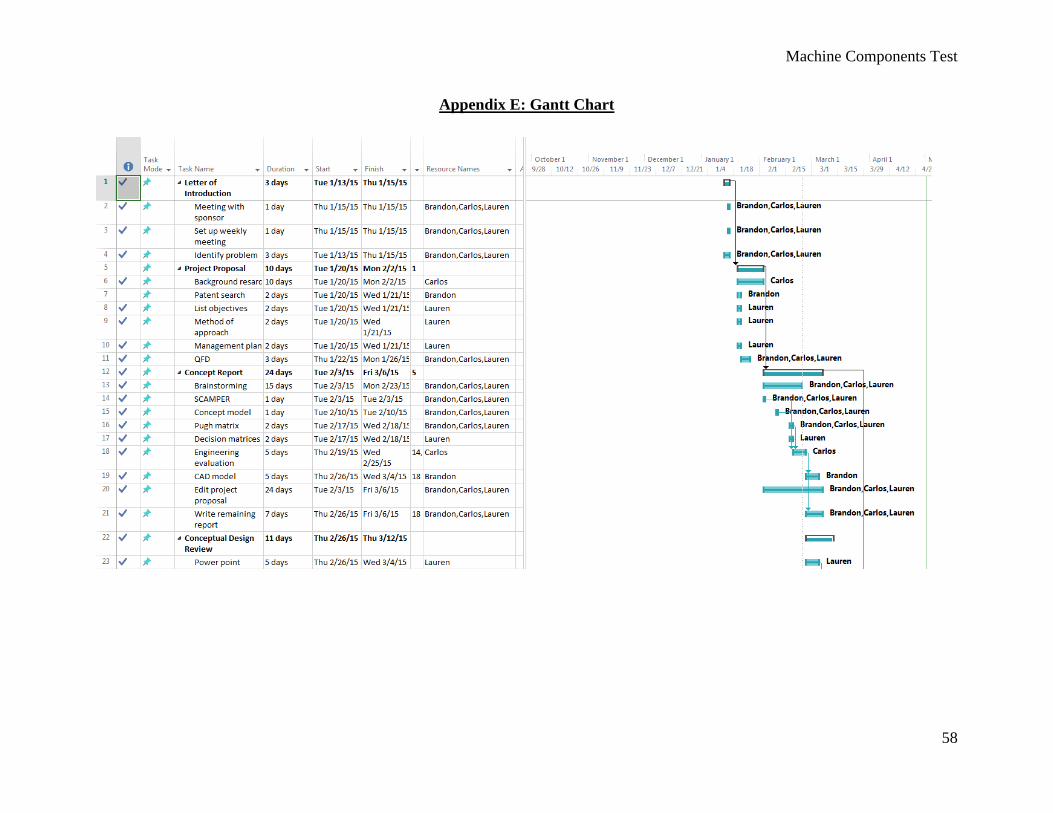
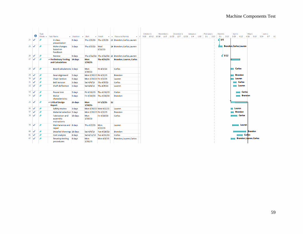
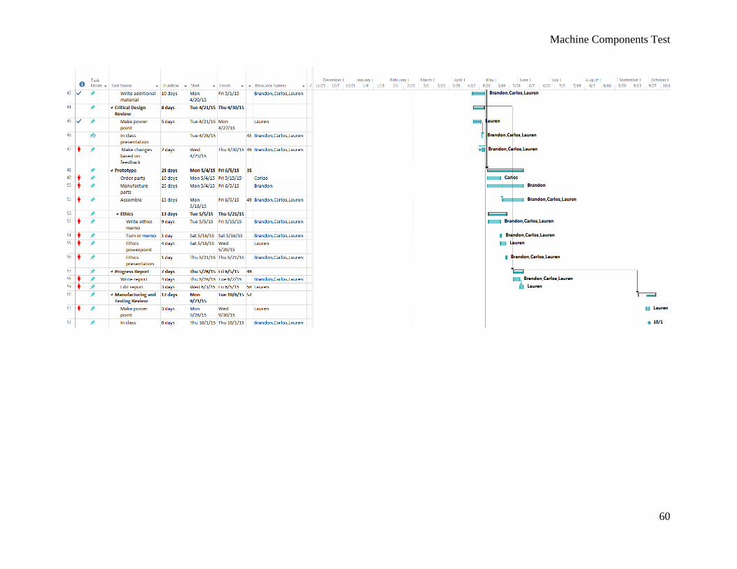
Appendix E displays a Gantt chart of how our project will be divided between team members
and what parts are left to complete. Green check marks indicate the job has been completed. For
jobs not yet finished, the blue bars indicate the length of a specific job and the dark blue line
inside the bar signifies how much of the job has been completed. Furthermore, each job has a list
of names for the individual(s) in charge of the job. The Gantt chart is a helpful tool to keep the
team on track with the many aspects of the project, and to record our progress. The next
milestones in our project include a final concept review, a progress report, the Senior Project
Expo, and a final project report.
The major jobs of this project have been split up in the following manner. Our main contact and
direct connection to our sponsor is Brandon Younger. He is in charge of sending our sponsor all
reports and other necessary information. By contacting Brandon, our sponsor is contacting our
entire team. Manufacturing considerations will also be handled by Brandon Younger. As a
machine shop technician in Cal Poly’s machine lab, his knowledge of machines and
manufacturing will be utilized. He will also have primary responsibility for prototyping. This job
involves making a scale model in SolidWorks and editing the design drawings.
Information gathering will primarily be done by Carlos Padilla. This includes gathering
information for the background segment of the report. The bulk of the analysis will also be
Padilla’s responsibility. He will make calculations based on our design ideas to determine
whether or not our ideas will be possible as well as to delegate calculations to other team
members in order to make the job quicker. Purchasing will be handled by Carlos Padilla as well.
Many websites offer similar products, so it is Padilla’s responsibility to find which sources will
be the most cost effective, and produce a cost analysis based on his findings. Once part lists are
approved, Padilla will purchase the parts using project funding.
Lauren Romero is responsible for the documentation of the project. Her job will be to edit
reports and be in charge of formatting. Additionally, she is in charge of updating the Gantt chart
and product management as the project progresses. She has the role of recorder and will take
notes during sponsor meetings and make sure everyone can get the information. Additionally,
she will be in charge of safety, making sure the team takes proper precautions and that the final
product is safe for student use. Finally, Lauren Romero will be handling testing plans and design
revisions. Romero will develop testing apparatuses, and record data from various tests to ensure
accuracy and safety with the product.
Machine Components Test
39
Chapter 5: Product Realization
Manufacturing Processes Employed
CNC
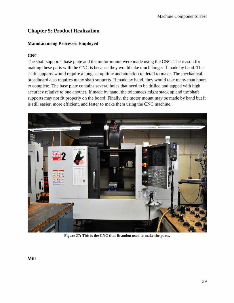
The shaft supports, base plate and the motor mount were made using the CNC. The reason for
making these parts with the CNC is because they would take much longer if made by hand. The
shaft supports would require a long set up time and attention to detail to make. The mechanical
breadboard also requires many shaft supports. If made by hand, they would take many man hours
to complete. The base plate contains several holes that need to be drilled and tapped with high
accuracy relative to one another. If made by hand, the tolerances might stack up and the shaft
supports may not fit properly on the board. Finally, the motor mount may be made by hand but it
is still easier, more efficient, and faster to make them using the CNC machine.
Figure 27: This is the CNC that Brandon used to make the parts.
Mill
Machine Components Test
40
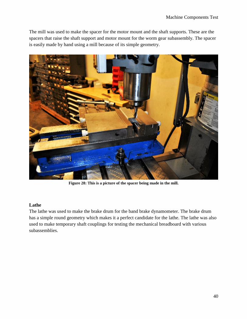
The mill was used to make the spacer for the motor mount and the shaft supports. These are the
spacers that raise the shaft support and motor mount for the worm gear subassembly. The spacer
is easily made by hand using a mill because of its simple geometry.
Figure 28: This is a picture of the spacer being made in the mill.
Lathe
The lathe was used to make the brake drum for the band brake dynamometer. The brake drum
has a simple round geometry which makes it a perfect candidate for the lathe. The lathe was also
used to make temporary shaft couplings for testing the mechanical breadboard with various
subassemblies.
Machine Components Test
41
Figure 29: Temporary shaft couplings were made using delrin plastic on the lathe.
Prototype Differences
The differences between the prototype and the final design will be minimal. There are only three
things that will be different from the prototype and the final design. The first is the shaft
couplings, for most of the testing we used temporary shaft couplings made of delrin plastic. The
final design will have aluminum shaft couplings that were ordered from McMaster Carr. The
second difference will be the prototype polycarbonate cover (not shown) will not have the safety
switch circuit as discussed for the design. The third is that the light up circuit that is powered by
the generator will not have a cover for the prototype.
Future Manufacturing Recommendations
In the future we recommend making the CNC parts in larger batches to optimize the use of the
machine. To make the spacer more efficiently we recommend machining the aluminum bar to
the correct height first, making the correct hole pattern, then cutting the aluminum to length.
Implementing these two recommendations will help reduce the manufacturing time and cost.
Machine Components Test
42
Chapter 6: Testing
Motor
The motor works nicely with the system. It is a Mabuchi RS-385PH and has motor characteristic
as shown in Appendix N. It should be noted that the motor is directional and must be connected
with the positive terminal connected to the terminal on the motor marked by the red dot.
Spur Gear Assembly
The spur gear assembly was one of the easiest to test. It was easy to put together and did not
generate any significant concerns. The first time the spur gear assembly was tested it was done
without thrust bearings. Although there should be no thrust, it seemed that when the motor was
turned on the vibrations of the assembly would thrust the shaft toward one of the shaft collars.
This created a significant amount of friction and slowed the motor down considerably. In order
to avoid this we added the thrust bearings in the spur gear assembly. With the thrust bearings on,
the system worked more efficiently. The mesh of the gears can also easily be tuned with the
thumb screws. When the two base plates touch the gears are slightly under meshed. As the thumb
screws are tightened the mesh can be optimized and even over meshed.
Figure 30: This is a photo of the complete prototype spur gear assembly.
Machine Components Test
43
Chain and Sprocket Assembly
The chain and sprocket assembly was the first subassembly to be tested. This assembly was
sensitive to misalignment of the sprockets. The sprockets needed to be iteratively adjusted until
the system rotated freely. This system was tested without the use of thrust bearings. There was
no apparent difference when the thrust bearings were installed. This system was also sensitive to
chain tension. It is noisy when the chain is slack and the shafts want to stop rotating if the chain
is too tight.
Figure 31: Picture of the chain and sprocket assembly
Flat Belt and Pulley Assembly
The flat belt assembly was the easiest to install. The pulleys have to be aligned so that the flat
belt does not come off, but other than that it seemed to work nicely. The tension of the belt has to
also be optimized for performance. If the belt is loose then it will slip.
Machine Components Test
44
Figure 32: This is the completed belt and pulley assembly. Note that temporary shaft couplings are shown in
this picture. Also not the configuration of the motors.
Worm Gear Assembly
This was the most difficult assembly to construct. A special spacer had to be made in order to
make this assembly work. The spacer is manufactured to be a littler larger than the correct height
for the gears so that the gears are under meshed when the screws first begin to press against the
shaft support. As the screws are tightened the meshing of the worm and worm gear can be
adjusted and even over meshed by tightening the screws too much.
Machine Components Test
45
Figure 33: This is a picture of the worm gear assembly without the motor or the generator.
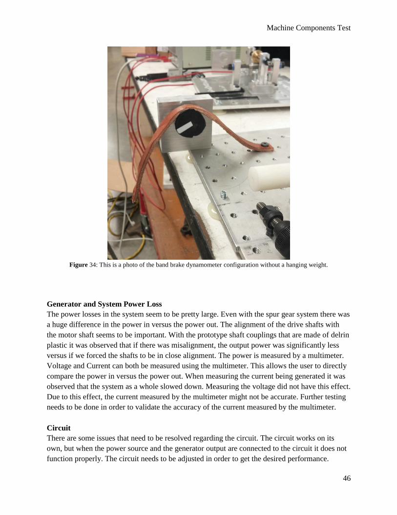
Band Brake Dynamometer
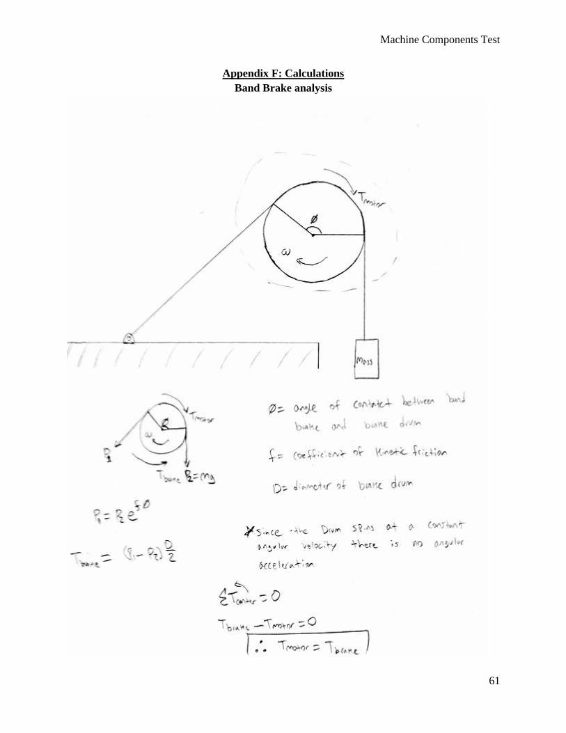
The band brake dynamometer test set up worked better than expected. When the test data was
compared to the published motor data, the torque that we calculated was within 2% of the
published data. The speed of the motor on the other hand was not as consistent with published
data, but it was still within about 12%. In order for the band brake calculations to be valid the
motor must be spinning in the direction as shown in Appendix F. There are two critical
components to calculating the torque of the motor correctly. The first is the angle of wrap of the
belt on the brake drum. This can be easily calculated because the geometry of the dynamometer
is known. The second is the friction coefficient between aluminum brake drum and the leather
belt. Testing can be conducted to calculate the friction factor or, as in our case, assumed to be
0.4.
Machine Components Test
46
Figure 34: This is a photo of the band brake dynamometer configuration without a hanging weight.
Generator and System Power Loss
The power losses in the system seem to be pretty large. Even with the spur gear system there was
a huge difference in the power in versus the power out. The alignment of the drive shafts with
the motor shaft seems to be important. With the prototype shaft couplings that are made of delrin
plastic it was observed that if there was misalignment, the output power was significantly less
versus if we forced the shafts to be in close alignment. The power is measured by a multimeter.
Voltage and Current can both be measured using the multimeter. This allows the user to directly
compare the power in versus the power out. When measuring the current being generated it was
observed that the system as a whole slowed down. Measuring the voltage did not have this effect.
Due to this effect, the current measured by the multimeter might not be accurate. Further testing
needs to be done in order to validate the accuracy of the current measured by the multimeter.
Circuit
There are some issues that need to be resolved regarding the circuit. The circuit works on its
own, but when the power source and the generator output are connected to the circuit it does not
function properly. The circuit needs to be adjusted in order to get the desired performance.
Machine Components Test
47
Set-Up Time
While testing the time to set up the mechanical breadboard it was evident that subassemblies are
required in order to speed up the process. It was found that it takes 6 minutes to set up the base
plate with the rod ends and feet. It also takes 10 minutes to set up the chain and sprocket
assembly. With the chain and sprocket assembly and the base plate pre-assembled it only took
2.5 minutes to get the mechanical breadboard ready.
Chapter 7: Conclusion and Recommendations
As this project comes to a close it should be noted that the final prototype will be about 90%
complete. There are a few things that need to be iterated and retested in order to finalize this
project. The system as a whole works very well. The small nuances of each assembly will give
students a chance to understand different mechanical systems on a deeper level.
This project did cost more than expected. The target goal was to make a complete system with a
budget of only $300. This project cost more than that, but there are a few ways to minimize the
cost. One way is to share some of the subassemblies with different groups. This divides the cost
of a subassembly over a number of mechanical breadboards. Another way to minimize cost is to
use more plastic parts where metal is not needed. For example, the metal gears can be replaced
with plastic gears. The initial reasoning behind metal gears was to give students a more
“realistic” experience with mechanical components.
There are a few things that need to be addressed in order to successfully implement the
mechanical breadboard in lab. The first thing is the circuit needs to be modified to get the desired
output. The circuit it not a critical component of the lab, but it does provide fast visual feedback
to the user. A critical component of the lab is the ability to measure the power generated by the
mechanical components. Power generation measurement needs to be tested further to access its
accuracy. While testing the motor generator it was noted that measuring current using a
multimeter slowed the system down versus measuring the voltage. This needs to be resolved
before the mechanical breadboard can be used successfully in lab.
During our testing we noticed a lot of vibrations. Currently the design does not address a way to
reduce mechanical vibrations. The vibrations can be loud and distracting at times. An
improvement that can be made is to fix the feet that screw into the base plate since the feet screw
in to the base plate and have a tendency to move in or out of the plate. This leads to tilting and
uneven mating of the two plates. The rod ends and nut combination that is used to adjust the gap
between the two plates can also be improved. The current design works, but it can made to be
more user friendly. There may also be a purchasable assembly that performs the desired action,
but we could not find one. Lastly, the safety cover can also be improved. The prototype is just a

Machine Components Test
48
box that surrounds the mechanical breadboard assembly. A circuit can be integrated with the
safety cover that would prevent the motor from running if the cover is not positioned correctly.
These are just a few things that may be improved during the next iteration of this project.
Machine Components Test
49
Appendix A: References
[1] Beardsley, R., & Pringle, C., “Machine Design Lab: Using Automotive Transmission
Examples to Reinforce Understanding of Gear Train Analysis: American Society for
Engineering Education”, Asee.org, 2015. [Online]. Available:
http://www.asee.org/public/conferences/1/papers/838/view. [Accessed: 03- Feb- 2015].
[2] Marra, S., “Development and Evolution of a New Mechanical Design Laboratory Course:
American Society for Engineering Education”, asee.org, 2014. [Online]. Available:
http://www.asee.org/public/conferences/32/papers/9027/view. [Accessed: 03- Feb- 2015].
[3] “Cornell University Law School: 29 CFR 1910.219 - Mechanical power-transmission
apparatus”. [Online]. Available: http://www.law.cornell.edu/cfr/text/29/1910.219. [Accessed: 02-
Feb- 2015].
[4] Mikes, J., “The Analysis and Development of a Mechanical Breadboard Structure”,
http://www.dtic.mil, 2006, [Online]. Available:
http://www.dtic.mil/dtic/tr/fulltext/u2/a461564.pdf. [Accessed: 25-Feb-2015].
[5] Van, D., Ward, D., “Designing a Mechanical Breadboard for Effective Teaching of
Engineering Statics”, asee.org, 2004. [Online]. Available:
http://search.asee.org/search/fetch?url=file%3A%2F%2Flocalhost%2FE%3A%2Fsearch%2Fcon
ference%2F28%2FAC%25202004Paper115.pdf&index=conference_papers&space=1297467972
03605791716676178&type=application%2Fpdf&charset=. [Accessed: 25-Feb-2015].
[6] Mountain, J.R.; Hibbeler, L.C., "Hands-On Process Control Experiences: A Curriculum
Integration Experiment," Frontiers in Education Conference, 36th Annual , vol., no., pp.7,12,
27-31 Oct. 2006
[7] “Rebuilding the Makita Battery Pack”, Kichline.com. [Online]. Available:
http://chuck.kichline.com/fixit/makita/default.htm. [Accessed: 03- March- 2015].
[8] “Spur Gears with a chain and tensioner Version 2”, Youtube.com, 2015. [Online]. Available:
https://www.youtube.com/watch?v=NjTmcUm1QFI. [Accessed: 03- March- 2015].
[9] “Lawler Gears”, Lawler Gear Corp., 2015. [Online]. Available:
http://www.lawlergear.com/PageContent/services.html. [Accessed: 03- March- 2015].
[10] “Makita 6406”, Tool Parts Pro, 2015. [Online]. Available:
http://www.toolpartspro.com/makita-parts/makita-6406-parts.html. [Accessed: 03- March-
2015].
Machine Components Test
50
[11] MJER, “Kinetic Sculpture: “Sine Machine””, Instructables, 2015. [Online].
Available:http://www.instructables.com/id/Kinetic-Sculpture-Sine-Machine/. [Accessed: 03-
March- 2015].
[12] Ehud Riven, “Amazing Steampunk Wine Bottle Opener”, Walyou, 2015. [Online]
Available:http://walyou.com/steampunk-wine-bottle-
opener/?utm_source=feedburner&utm_medium=email&utm_campaign=Feed:+TheWalyouBlog
+(The+Walyou+Blog). [Accessed: 03- March- 2015].
[13] “Warning Safety Label: Moving Parts Can Crush And Cut, Keep Hands Clear While
Operating Machine”,My Safety Labels, 2015. [Online]
Available:http://www.mysafetylabels.com/Warning-Labels/Moving-Parts-Can-Crush-Safety-
Label/SKU-LB-0356.aspx. [Accessed: 09- April- 2015].
Machine Components Test
51
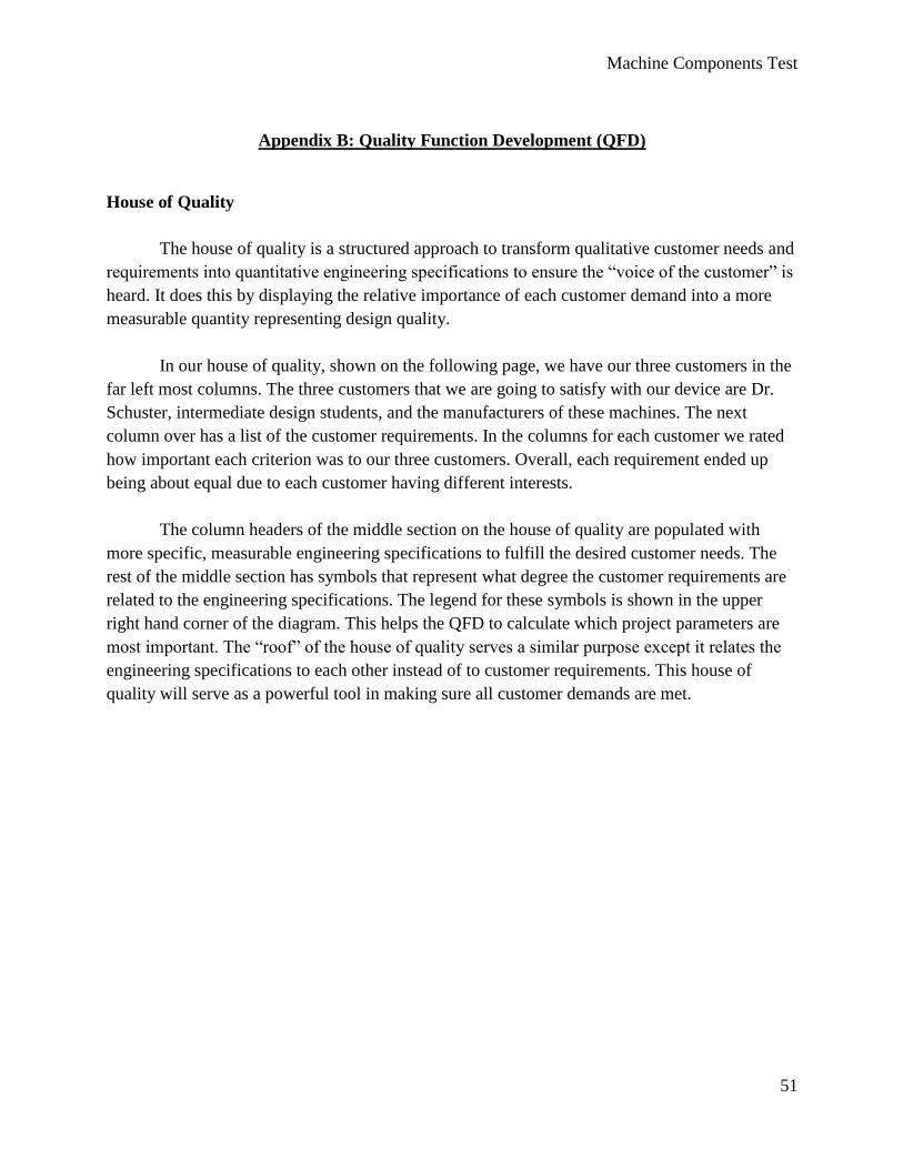
Appendix B: Quality Function Development (QFD)
House of Quality
The house of quality is a structured approach to transform qualitative customer needs and
requirements into quantitative engineering specifications to ensure the “voice of the customer” is
heard. It does this by displaying the relative importance of each customer demand into a more
measurable quantity representing design quality.
In our house of quality, shown on the following page, we have our three customers in the
far left most columns. The three customers that we are going to satisfy with our device are Dr.
Schuster, intermediate design students, and the manufacturers of these machines. The next
column over has a list of the customer requirements. In the columns for each customer we rated
how important each criterion was to our three customers. Overall, each requirement ended up
being about equal due to each customer having different interests.
The column headers of the middle section on the house of quality are populated with
more specific, measurable engineering specifications to fulfill the desired customer needs. The
rest of the middle section has symbols that represent what degree the customer requirements are
related to the engineering specifications. The legend for these symbols is shown in the upper
right hand corner of the diagram. This helps the QFD to calculate which project parameters are
most important. The “roof” of the house of quality serves a similar purpose except it relates the
engineering specifications to each other instead of to customer requirements. This house of
quality will serve as a powerful tool in making sure all customer demands are met.
Machine Components Test
52
Machine Components Test
53
Appendix C: Pugh Matrix
Pugh Matrix
Concept 1 2 3 4 5 6 7 8
Criteria
A D S S - - - - S
B S S + - + - -
C A - - + - + - -
D + + - + + + +
E T + - - + - + +
F S - + - - + -
G U - - - - - - +
H - S + - - - -
I M + - - + + + -
J + S S - - - -
K S - + - - + -
L - S + - - - -
M + + - + + - +
N + + - + + + +
O + + + + - - S
Sum + 0 7 4 7 6 6 6 5
Sum - 0 4 6 7 9 9 9 8
Sum S 0 4 5 1 0 0 0 2
Machine Components Test
54
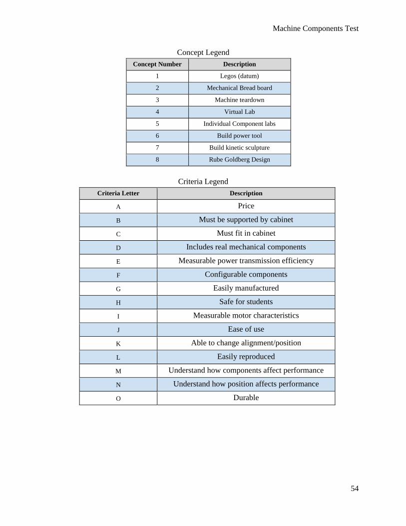
Concept Legend
Concept Number Description
1 Legos (datum)
2 Mechanical Bread board
3 Machine teardown
4 Virtual Lab
5 Individual Component labs
6 Build power tool
7 Build kinetic sculpture
8 Rube Goldberg Design
Criteria Legend
Criteria Letter Description
A Price
B Must be supported by cabinet
C Must fit in cabinet
D Includes real mechanical components
E Measurable power transmission efficiency
F Configurable components
G Easily manufactured
H Safe for students
I Measurable motor characteristics
J Ease of use
K Able to change alignment/position
L Easily reproduced
M Understand how components affect performance
N Understand how position affects performance
O Durable
Machine Components Test
55
Appendix D: Decision Matrices
Methods of Attachment
Design Criteria A B C D E F G H I
Weight 0.2 0.2 0.05 0.05 0.2 0.1 0.15 0.05 1
Alternatives
Magnets 90 30 90 90 80 50 60 100
18 6 4.5 4.5 16 5 9 5 68
Threaded 90 70 80 95 95 90 90 100
Fasteners 18 14 4 4.75 19 9 13.5 5 69.25
Clamps 70 70 60 100 80 70 70 100
14 14 3 5 16 7 10.5 5 60.5
Multiple Fixed 100 70 100 70 100 90 100 0
Setups 20 14 5 3.5 20 9 15 0 66.5
Rod and Cotter 90 100 90 80 80 100 20 100
Pin Assembly 18 20 4.5 4 16 10 3 5 62.5
Methods of Attachment Legend
Criteria Letter Description
A Ease of Use
B Cost
C Setup Time
D Machining Time
E Safety
F Durability
G Vibrations
H Configurability
I Overall Satisfaction
Machine Components Test
56
Storage
Design Criteria A B C D E F G H I J
Weight 0.15 0.2 0.05 0.1 0.15 0.05 0.05 0.05 0.2 1
Alternatives
Foldable 70 60 70 60 70 70 70 70 80
10.5 12 3.5 6 10.5 3.5 3.5 3.5 16 69
Detachable 60 70 70 70 80 70 70 70 80
9 14 3.5 7 12 3.5 3.5 3.5 16 72
Cover 80 80 90 90 100 90 90 90 50
12 16 4.5 9 15 4.5 4.5 4.5 10 80
Bin 100 80 90 100 100 90 90 90 60
15 16 4.5 10 15 4.5 4.5 4.5 12 86
Storage Legend
Criteria Letter Description
A Ease of Use
B Cost
C Setup Time
D Machining Time
E Safety
F Durability
G Reliability
H Reparability
I Space
J Overall Satisfaction
Machine Components Test
57
Output
Design Criteria A B C D E F G H I J
Weight 0.1 0.15 0.05 0.05 0.2 0.05 0.15 0.05 0.2 1
Alternatives
Ball and Fan 100 100 80 90 80 80 90 50 80
10 15 4 4.5 16 4 13.5 2.5 16 85.5
Ball Launcher 100 100 60 80 70 80 70 90 60
10 15 3 4 14 4 10.5 4.5 12 77
Light 100 80 100 100 100 100 30 50 90
10 12 5 5 20 5 4.5 2.5 18 82
Generator 80 80 80 100 70 80 100 50 50
8 12 4 5 14 4 15 2.5 10 74.5
Output Legend
Criteria Letter Description
A Ease of Use
B Visual Appeal
C Setup Time
D Fabrication Time
E Safety
F Durability
G Measurability
H Reparability
I Cost
J Overall Satisfaction
Machine Components Test
58
Appendix E: Gantt Chart
Machine Components Test
59
Machine Components Test
60
Machine Components Test
61
Appendix F: Calculations
Band Brake analysis
Machine Components Test
62
Spur Gear Analysis
Machine Components Test
63
Machine Components Test
64
Machine Components Test
65
Worm Gear Analysis
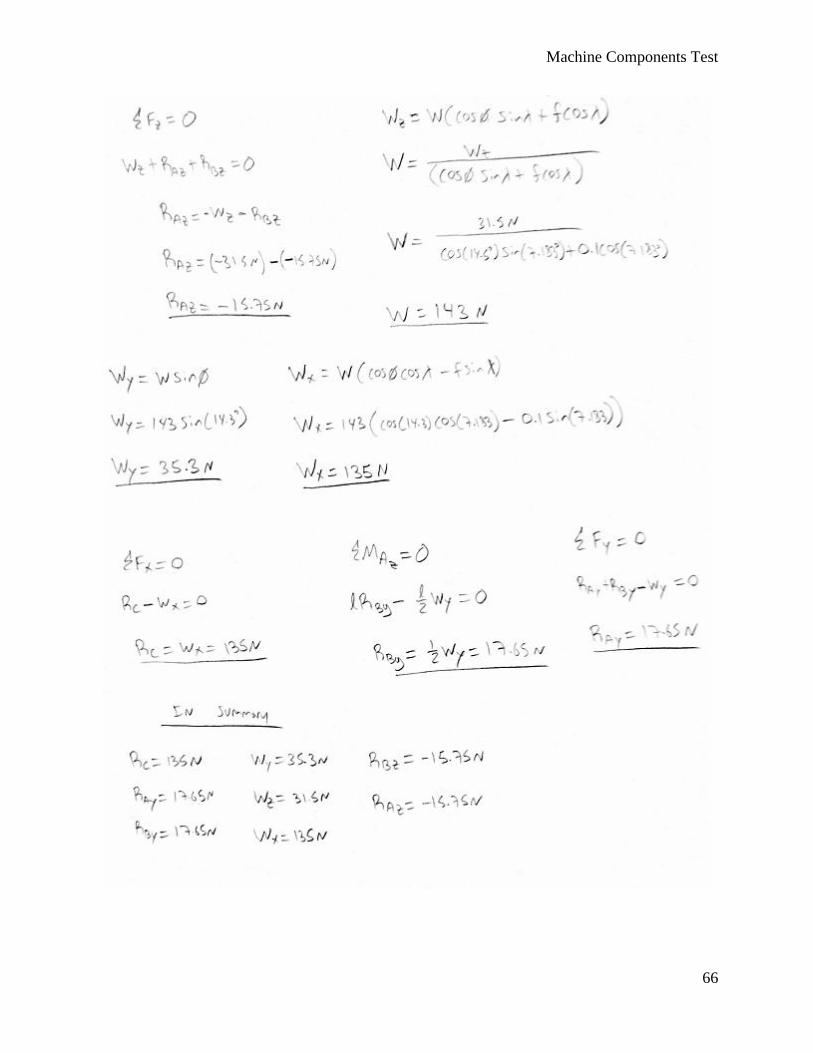
Machine Components Test
66
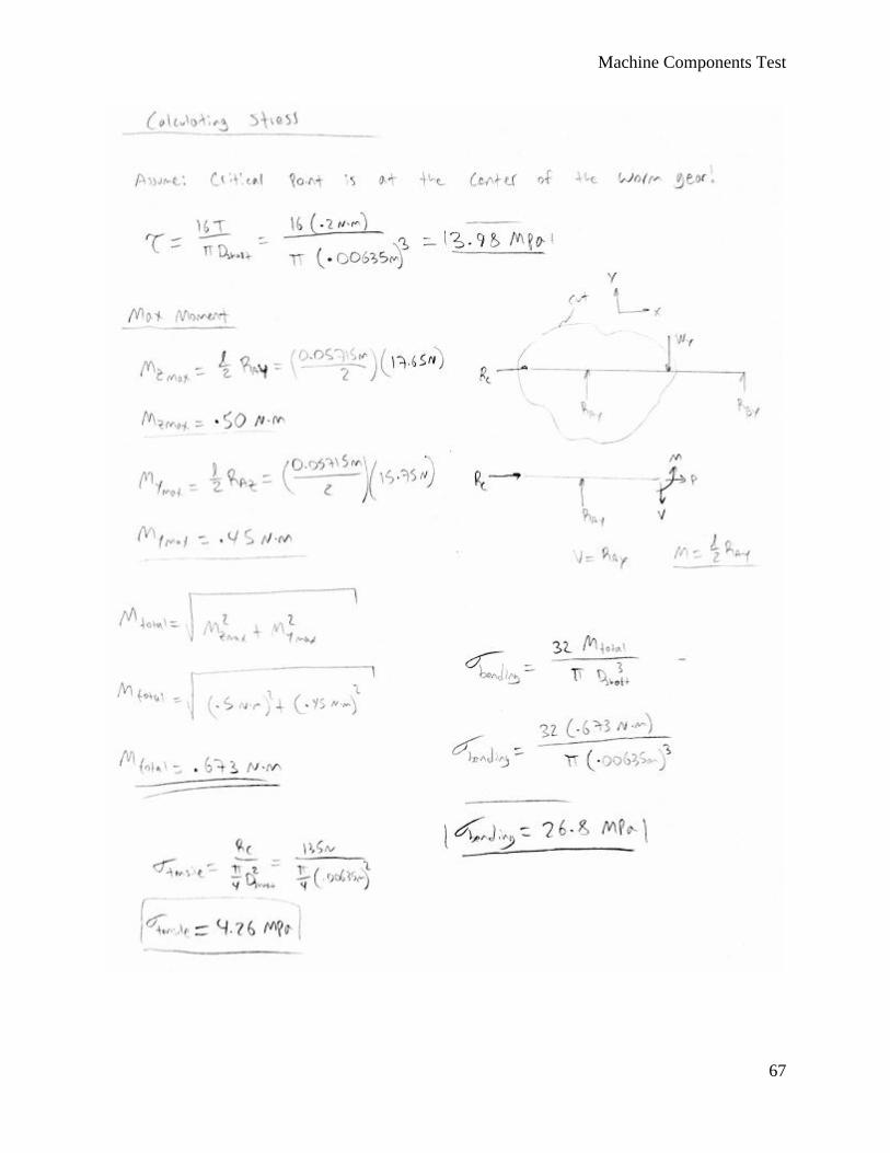
Machine Components Test
67
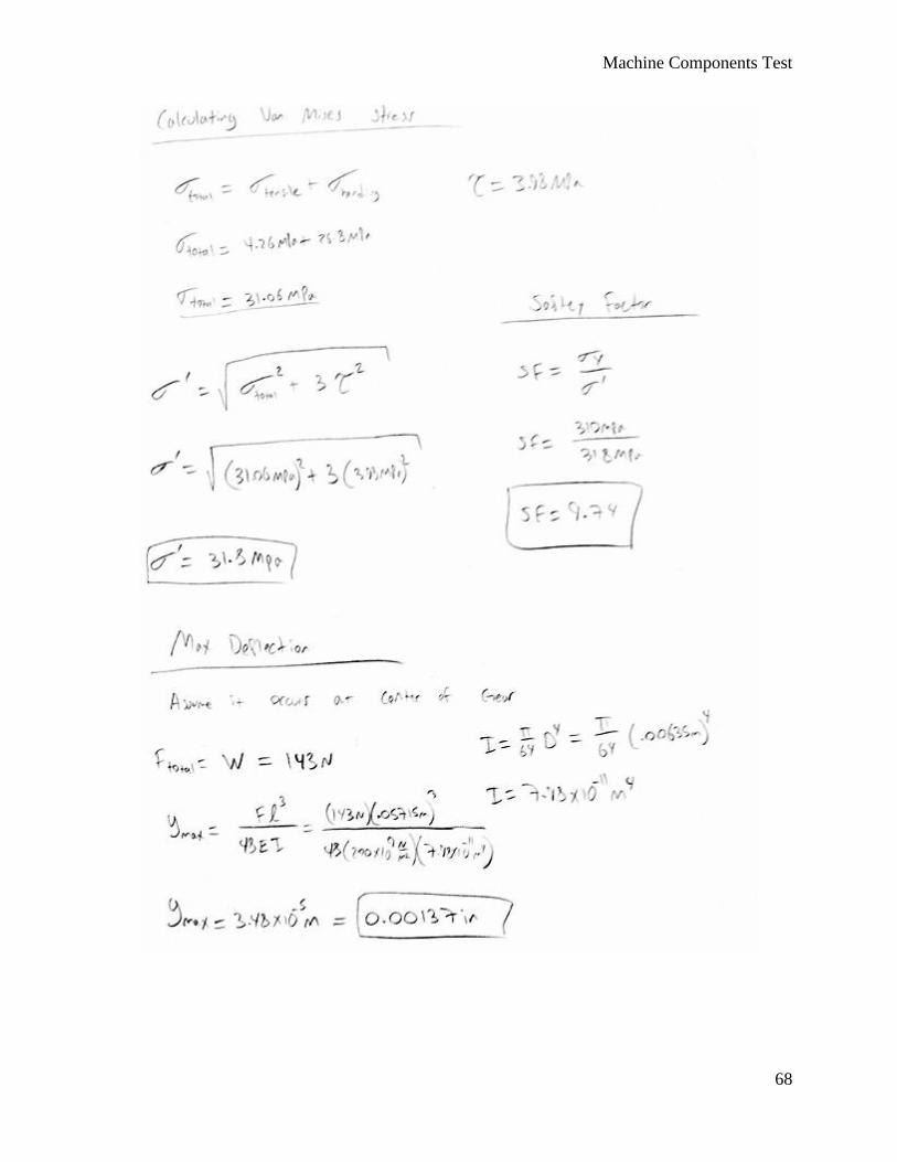
Machine Components Test
68
Machine Components Test
69
Appendix G: FMEA Chart
Failure Mode and Effect Analysis for Mechanical Breadbaord
Item / Function
Potential Failure Mode
Potential Effect(s) of Failure
Sev
Potential Cause(s) / Mechanism(s) of
Failure Occur Crit Recommended Action(s)
Responsibility & Target Completion
Date
Board Stripped threads in holes
Components do not secure onto board
5 Overused, too much pulling when removing screws
7 35 Include instructions on how to install components, use harder material than fasteners
Lauren 5/15/15
Shafts Bending and fracture
Components do not line up
4 High forces on shafts 4 16 Lower forces Brandon 5/15/15
Belts Improper operating tension
Belt failure, slipage, and fatigue
5 Installation error, too little or too much tension
4 20 Include instructions on how to install components
Carlos 5/15/15
Belts Misalignment Sidewall cracking, belt failure
4 Installation error 4 16 Include instructions on how to install components
Lauren 5/20/15
Chain Rubbing wear Chain wears a groove in the fixture
2 Misalignment of chain 4 8 Include instructions on how to install components
Brandon 5/20/15
Chain Fretting corrosion
Impaired function, unsatisfactory appearance
2 Not enough lubrication
4 8 Lubrication Carlos 5/20/15
Bearings Bearing wear Misalign gears and other components
3 Contaminants, too much force, friction
4 12 Lubrication Lauren 5/25/15
Gears Gear wear Gear slipping 4 Not enough lubrication, misalignment
4 16 Include instructions on how to install components, lubrication
Brandon 5/25/15
Gears Pitting Redistributes the load
3 Misalignment, surface irregularities
4 12 Include instructions on how to install components
Carlos 5/25/15
Threaded fasteners
Stripped threads
Components do not stay fixed
5 Over used, too much pulling when removing screws
7 35 Include instructions on how to install components, have extra fasteners
Lauren 5/30/15
Motor Overheating Insulation deteriorates, loss of function
4 Overloading the motor
5 20 Automatic shutoff when forces become too high
Brandon 5/30/15
Generator Overheating Insulation deteriorates, loss of function
4 Overloading the generator
5 20 Automatic shutoff when voltage becomes too high
Carlos 5/30/15
Machine Components Test
70
Machine Components Test
71
Appendix H: DVP Chart
Design Verification Plan and Report for Mechanical Breadboard
Report Date: 3/12/2015 Sponsor: Peter Schuster Component/Assembly:
TEST PLAN Item No
Specification or Clause
Reference
Test Description
Acceptance Criteria
Test Responsibility
Test Stage
SAMPLES TESTED TIMING
Quantity Type Start date Finish date
1 Gear Alignment
Test to verify that Gears are in alignment
40 cycles Brandon Younger
DV 5 PASS 9/28/2015 9/30/2015
2
Chain Tension
Test to verify that sufficient tension exists in chain in proper orientation
40 cycles Lauren Romero
DV 5 PASS 10/1/2015 10/4/2015
3
Belt Tension Test to verify that sufficient tension exists in belt in proper orientation
40 cycles Carlos Padilla DV 5 PASS 10/5/2015 10/9/2015
4
Bearing Alignment
Test to verify that bearing are aligned successfully
10 cycles Brandon Younger
DV 5 PASS 10/5/2015 10/9/2015
5
Motor Load Test to verify that the motor can handle the loads of the various configurations
40 cycles Lauren Romero
DV 3 PASS
6
Setup Time Test to determine how long it takes to set
<10 minutes
Carlos Padilla DV 3 PASS 10/12/2015 10/12/2015
Machine Components Test
72
up the mechanism
8
Ability to accurately characterize the motor curve.
Test to determine the accuracy of the band brake dynamometer
±15% error Lauren Romero
DV 3 PASS
9
Assembly Time
Test to determine how long it take to assemble each mechanism
<3 hrs Carlos Padilla DV 1 PASS
10
Weight Test to determine overall weight of mechanism
<20 lbs Brandon Younger
DV 1 PASS
11
Size Test to determine the overall size of the mechanism
3'x2'x1' Lauren Romero
DV 1 PASS
12
Production Cost
Test to determine the overall cost of a system
$300 Carlos Padilla DV 1 FAIL
15
Configurable Components
Test the number of different configurations the design can do
>4 Brandon Younger
DV 1 PASS
Machine Components Test
73
Appendix I: Analysis Plan
Shaft with spur gear analysis model.
Shear Diagram of the shaft in the X-Y plane.
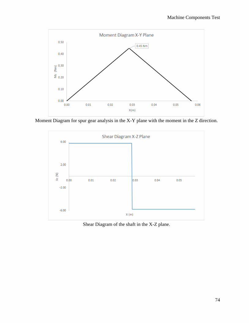
Machine Components Test
74
Moment Diagram for spur gear analysis in the X-Y plane with the moment in the Z direction.
Shear Diagram of the shaft in the X-Z plane.
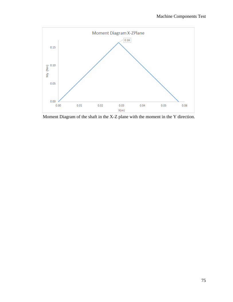
Machine Components Test
75
Moment Diagram of the shaft in the X-Z plane with the moment in the Y direction.
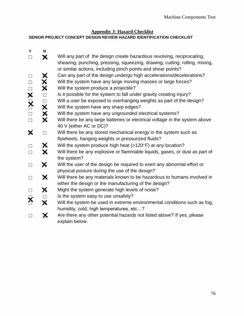
Machine Components Test
76
Appendix J: Hazard Checklist
SENIOR PROJECT CONCEPT DESIGN REVIEW HAZARD IDENTIFICATION CHECKLIST
Y N
Will any part of the design create hazardous revolving, reciprocating,
shearing, punching, pressing, squeezing, drawing, cutting, rolling, mixing,
or similar actions, including pinch points and shear points?
Can any part of the design undergo high accelerations/decelerations?
Will the system have any large moving masses or large forces?
Will the system produce a projectile?
Is it possible for the system to fall under gravity creating injury?
Will a user be exposed to overhanging weights as part of the design?
Will the system have any sharp edges?
Will the system have any ungrounded electrical systems?
Will there be any large batteries or electrical voltage in the system above
40 V (either AC or DC)?
Will there be any stored mechanical energy in the system such as
flywheels, hanging weights or pressurized fluids?
Will the system produce high heat (>120F) at any location?
Will there be any explosive or flammable liquids, gases, or dust as part of
the system?
Will the user of the design be required to exert any abnormal effort or
physical posture during the use of the design?
Will there be any materials known to be hazardous to humans involved in
either the design or the manufacturing of the design?
Might the system generate high levels of noise?
Is the system easy to use unsafely?
Will the system be used in extreme environmental conditions such as fog,
humidity, cold, high temperatures, etc…?
Are there any other potential hazards not listed above? If yes, please
explain below.
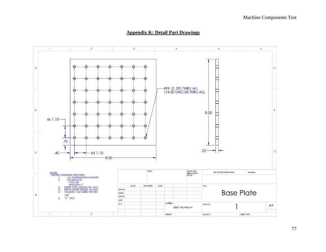
Machine Components Test
77
Appendix K: Detail Part Drawings
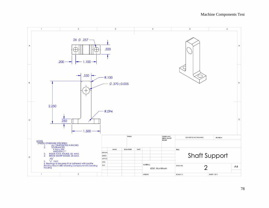
Machine Components Test
78
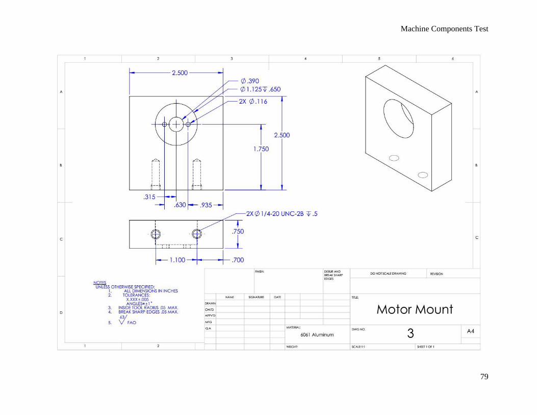
Machine Components Test
79
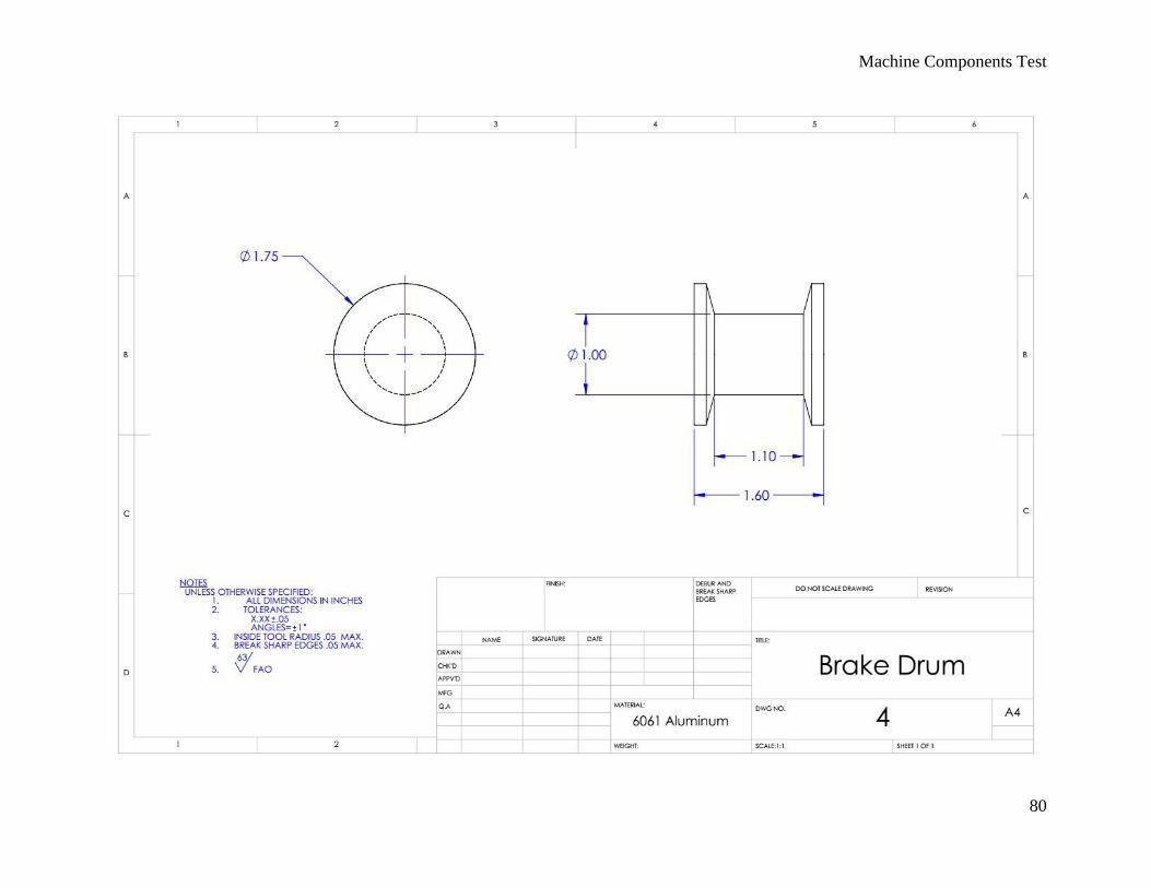
Machine Components Test
80
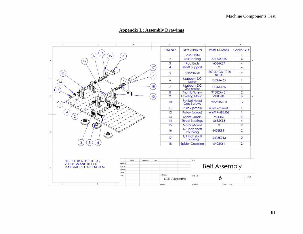
Machine Components Test
81
Appendix L: Assembly Drawings
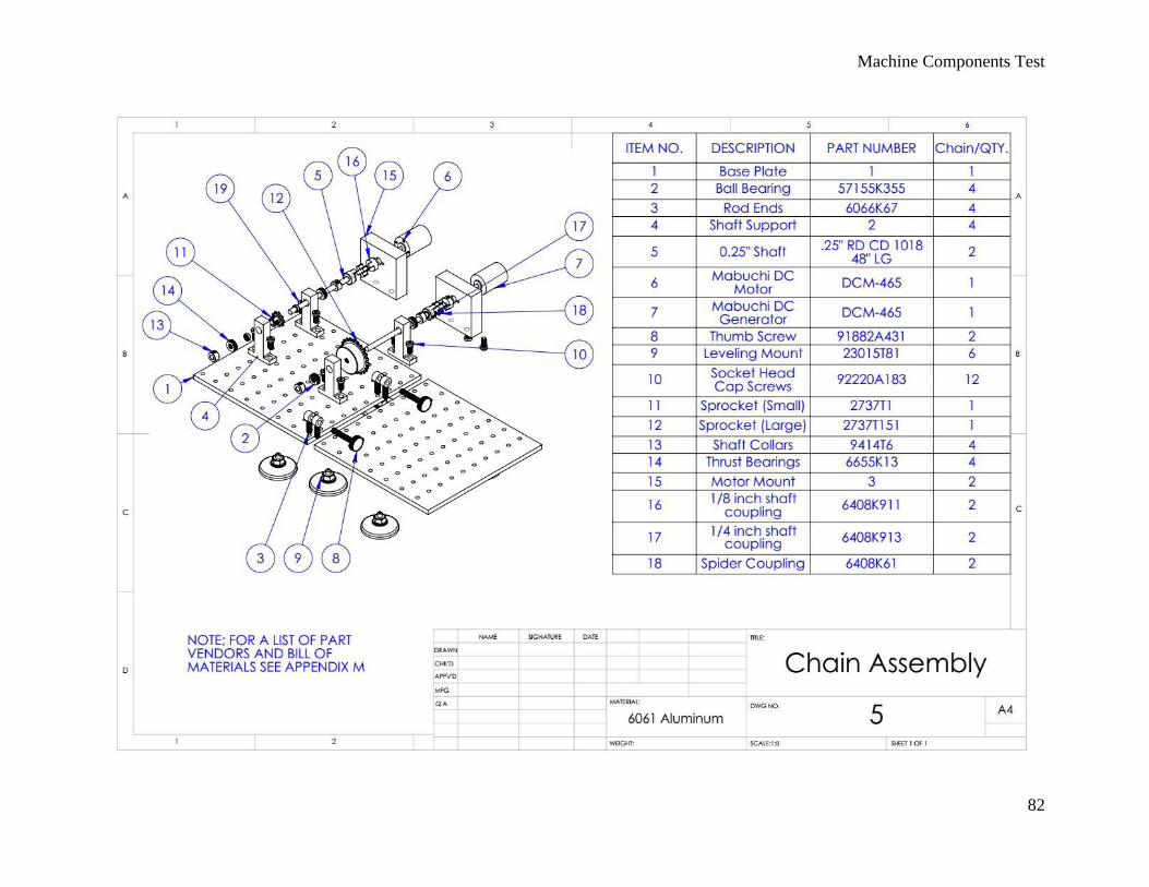
Machine Components Test
82
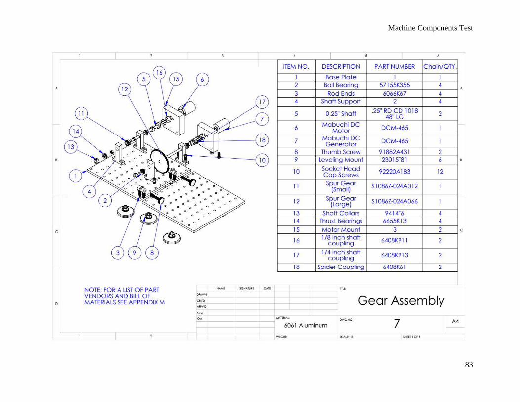
Machine Components Test
83
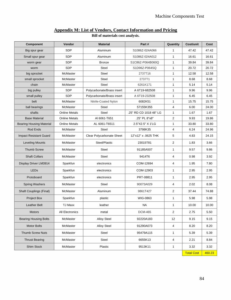
Machine Components Test
84
Appendix M: List of Vendors, Contact Information and Pricing
Bill of materials cost analysis.
Component Vendor Material Part # Quantity Cost/unit Cost
Big spur gear SDP Aluminum S1086Z-024A066 1 47.42 47.42
Small spur gear SDP Aluminum S1086Z-024A012 1 16.61 16.61
worm gear SDP Bronze S1C86Z-P064B060Q 1 39.84 39.84
worm SDP Steel S1D96Z-P064SQ 1 20.72 20.72
big sprocket McMaster Steel 2737T16 1 12.58 12.58
small sprocket McMaster Steel 2737T1 1 8.68 8.68
chain McMaster Steel 6261K171 1 5.14 5.14
big pulley SDP Polycarbonate/Brass insert A 6T19-682508 1 9.96 9.96
small pulley SDP Polycarbonate/Brass insert A 6T19-232508 1 6.45 6.45
belt McMaster Nitrile-Coated Nylon 6082K51 1 15.75 15.75
ball bearings McMaster Steel 57155K355 4 6.00 24.00
shafts Online Metals Steel .25" RD CD 1018 48" LG 1 1.67 1.67
Base Material Online Metals Al 6061-T651 .25" PL 8"x8" 2 9.93 19.86
Bearing Housing Material Online Metals AL 6061-T6511 2.5"X2.5" X 1'LG 1 33.80 33.80
Rod Ends McMaster Steel 3798K35 4 6.24 24.96
Impact Resistant Guard McMaster Clear Polycarbonate Sheet 12"x12" x .0625 THK 5 4.83 24.15
Leveling Mounts McMaster Steel/Plastic 23015T81 2 1.83 3.66
Thumb Screw McMaster Steel 91185A507 1 9.57 9.86
Shaft Collars McMaster Steel 9414T6 4 0.98 3.92
Display Driver LM3914 Sparkfun electronics COM-12694 4 1.95 7.80
LEDs Sparkfun electronics COM-12903 1 2.95 2.95
Protoboard Sparkfun electronics PRT-08811 1 2.95 2.95
Spring Washers McMaster Steel 90073A029 4 2.02 8.08
Shaft Couplings (Final) McMaster Aluminum 9861T427 2 37.44 74.88
Project Box Sparkfun plastic WIG-0863 1 5.98 5.98
Leather Belt TJ Maxx leather NA 1 10.00 10.00
Motors All Electronics metal DCM-465 2 2.75 5.50
Bearing Housing Bolts McMaster Alloy Steel 92220A183 12 9.15 9.15
Motor Bolts McMaster Alloy Steel 91290A073 4 8.20 8.20
Thumb Screw Nuts McMaster Steel 95479A115 1 5.39 5.39
Thrust Bearing McMaster Steel 6655K13 4 2.21 8.84
Shim Stock McMaster Plastic 9513K11 1 3.32 3.32
Total Cost 460.23
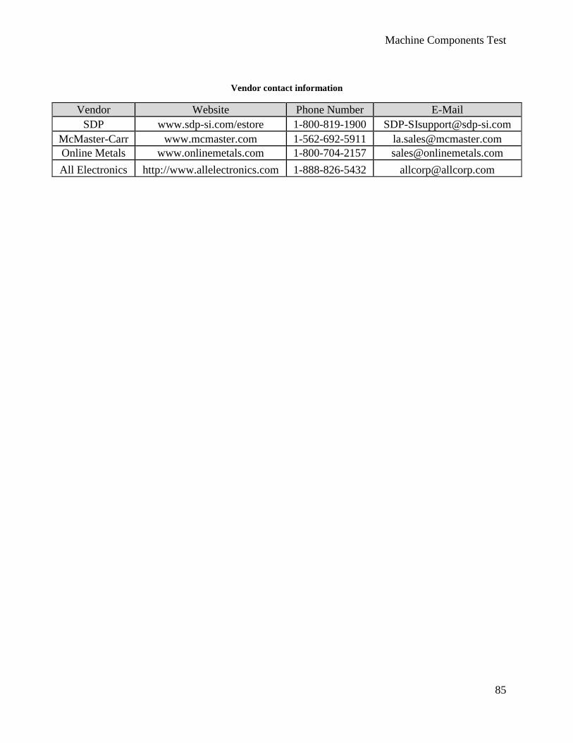
Machine Components Test
85
Vendor contact information
Vendor Website Phone Number E-Mail
SDP www.sdp-si.com/estore 1-800-819-1900 [email protected]
McMaster-Carr www.mcmaster.com 1-562-692-5911 [email protected]
Online Metals www.onlinemetals.com 1-800-704-2157 [email protected]
All Electronics http://www.allelectronics.com 1-888-826-5432 [email protected]
Machine Components Test
86
Appendix N: Published Motor Characteristics
Machine Components Test
87
Machine Components Test
88
Machine Components Test
89
Appendix O: Example Laboratory Instructions
Objective: Students will learn what different mechanical components (chains, belts,
and gears) can do, how they influence each other, and how they influence the system
as a whole.
Safety Checklist:
1. Long hair must be pulled back.
2. Long sleeves must be rolled up.
3. Safety glasses must be worn at all times.
4. Turn motor off, and wait until all components stop before rearranging components.
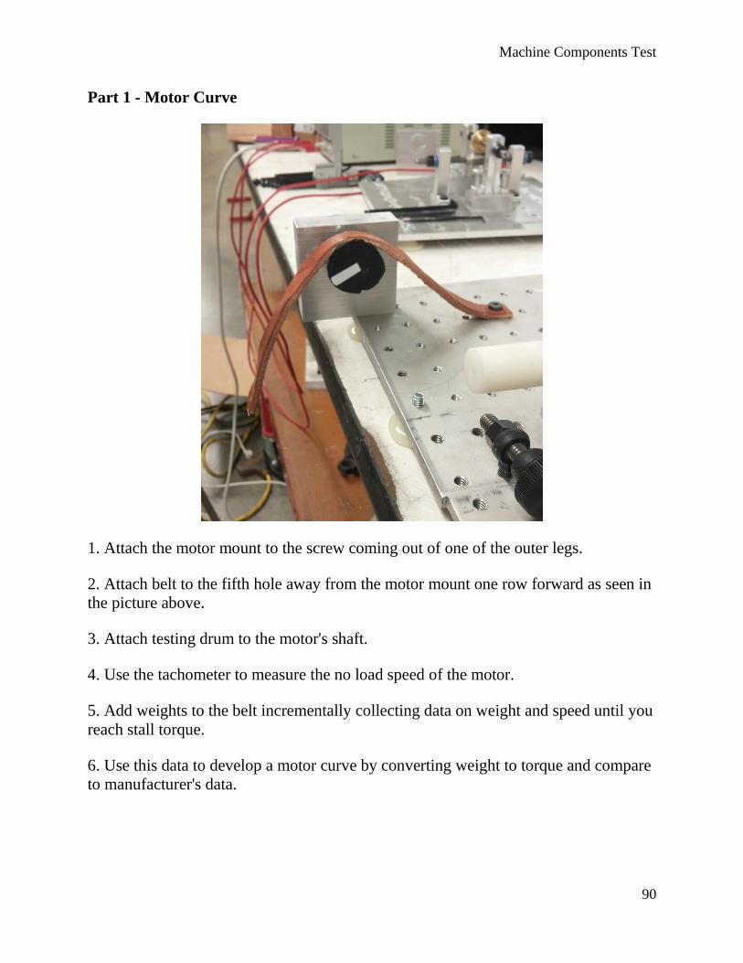
Machine Components Test
90
Part 1 - Motor Curve
1. Attach the motor mount to the screw coming out of one of the outer legs.
2. Attach belt to the fifth hole away from the motor mount one row forward as seen in
the picture above.
3. Attach testing drum to the motor's shaft.
4. Use the tachometer to measure the no load speed of the motor.
5. Add weights to the belt incrementally collecting data on weight and speed until you
reach stall torque.
6. Use this data to develop a motor curve by converting weight to torque and compare
to manufacturer's data.
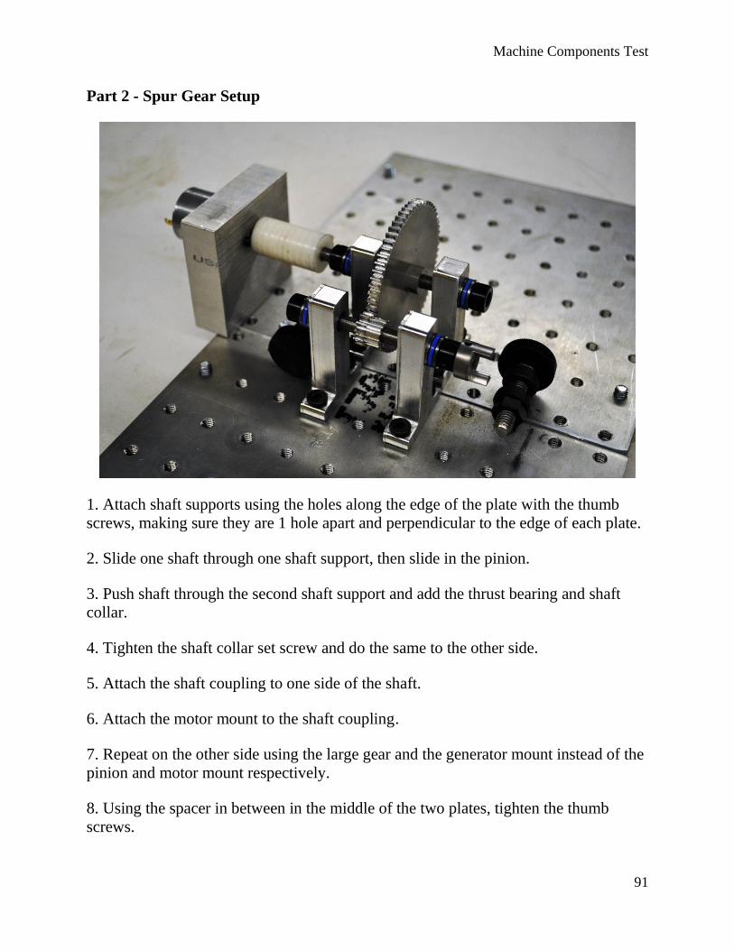
Machine Components Test
91
Part 2 - Spur Gear Setup
1. Attach shaft supports using the holes along the edge of the plate with the thumb
screws, making sure they are 1 hole apart and perpendicular to the edge of each plate.
2. Slide one shaft through one shaft support, then slide in the pinion.
3. Push shaft through the second shaft support and add the thrust bearing and shaft
collar.
4. Tighten the shaft collar set screw and do the same to the other side.
5. Attach the shaft coupling to one side of the shaft.
6. Attach the motor mount to the shaft coupling.
7. Repeat on the other side using the large gear and the generator mount instead of the
pinion and motor mount respectively.
8. Using the spacer in between in the middle of the two plates, tighten the thumb
screws.

Machine Components Test
92
9. Align the gears so they mesh and tighten their set screws.
10. Attach power source to the motor making sure to attach the positive end of the
power supply to the terminal of the motor that has a red circle next to it and slowly
increase the voltage until the gears start to move.
11. Record the input and output voltages.
12. Now remove the spacer and tighten the plates to perfectly mesh.
13. Again record the input and output voltages.
14. Repeat steps 10 and 11 after over meshing the gears.