Embed Size (px)
Citation preview
FINAL REPORT
Tom AprikNatalie HannonJeremy Konz
Don VanderLaan
Emergency Alert Response System (EARS) for the 21st Century AutomobileECE 480: Capstone Design Team 9
Michigan State University
December 3, 2008
Contents
1 Introduction and Background 2
2 Exploring the solution space and selecting a specific approach 3
2.1 Matched Filtering Algorithm and MATLAB . . . . . . . . . . . . . . . . . . 3
2.2 First Microcontroller: dsPIC30F . . . . . . . . . . . . . . . . . . . . . . . . . 3
2.2.1 Data Acquisition . . . . . . . . . . . . . . . . . . . . . . . . . . . . . 4
2.2.2 External Oscillator . . . . . . . . . . . . . . . . . . . . . . . . . . . . 4
2.2.3 Serial Peripheral Interface . . . . . . . . . . . . . . . . . . . . . . . . 4
2.2.4 Issues with dsPIC30F . . . . . . . . . . . . . . . . . . . . . . . . . . . 6
2.3 Second Microcontroller: dsPIC33F . . . . . . . . . . . . . . . . . . . . . . . 7
3 Technical description of work performed 7
3.1 Main Software Functionality . . . . . . . . . . . . . . . . . . . . . . . . . . . 7
3.2 ADC Function and DMA Interrupt . . . . . . . . . . . . . . . . . . . . . . . 8
3.3 Vector Dot Product . . . . . . . . . . . . . . . . . . . . . . . . . . . . . . . . 8
3.4 Change Notice pin . . . . . . . . . . . . . . . . . . . . . . . . . . . . . . . . 9
3.5 Thresholding . . . . . . . . . . . . . . . . . . . . . . . . . . . . . . . . . . . 9
3.6 Dynamic Scaling . . . . . . . . . . . . . . . . . . . . . . . . . . . . . . . . . 9
3.7 Hardware Design . . . . . . . . . . . . . . . . . . . . . . . . . . . . . . . . . 10
4 Test data with proof of functional design 13
5 Final cost, schedule, summary and conclusions 16
5.1 Final Budget . . . . . . . . . . . . . . . . . . . . . . . . . . . . . . . . . . . 16
5.2 Conclusion . . . . . . . . . . . . . . . . . . . . . . . . . . . . . . . . . . . . . 17
A Technical roles, responsibilities, and work accomplished 18
i
Emergency Alert Response System (EARS) for the 21st Century Automobile
A.1 Don VanderLaan . . . . . . . . . . . . . . . . . . . . . . . . . . . . . . . . . 18
A.2 Jeremy Konz . . . . . . . . . . . . . . . . . . . . . . . . . . . . . . . . . . . 19
A.3 Natalie Hannon . . . . . . . . . . . . . . . . . . . . . . . . . . . . . . . . . . 19
A.4 Tom Aprik . . . . . . . . . . . . . . . . . . . . . . . . . . . . . . . . . . . . . 20
B Literature and website references 21
C Detailed technical attachments 24
C.1 Software Flowcharts . . . . . . . . . . . . . . . . . . . . . . . . . . . . . . . 24
C.2 PCB Board Schematic . . . . . . . . . . . . . . . . . . . . . . . . . . . . . . 29
ii
Emergency Alert Response System (EARS) for the 21st Century Automobile
Executive Summary
Team 9 has designed and built an emergency alert response system, referred to as EARS,
intended for use in General Motors products. EARS listens for an emergency siren external
to the automobile using an audio sensor. Successful detection results in notification to the
driver of the presence of an emergency vehicle. The notification takes several forms reduction
in stereo volume and LED indicator display. The purpose of EARS is twofold to reduce
emergency response time by alerting drivers and reduce the number of emergency vehicle
crashes with unaware drivers.
Acknowledgement
Team 9 acknowledges Dr. Deller, professor at Michigan State University, for his guidance and
support throughout the semester. Team 9 also acknowledges General Motors for generous
sponsorship of the project.
1
Emergency Alert Response System (EARS) for the 21st Century Automobile
1 Introduction and Background
With 37,248 fatal vehicle crashes in the United States in 200711 increasing vehicle safety is
an important initiative for automotive companies. Currently, traffic signal preemption15 is
used to alert drivers of the presence of emergency vehicles in conjunction with the emergency
sirens and lights. Traffic signal preemption relies on an emitter on the emergency vehicle
to communicate with a detector mounted on a signal arm of a traffic light. Traffic signal
preemption is used to insure that emergency vehicles have a green light and thereby the right-
of-way through an intersection. However, traffic signal preemption is inherently problematic.
It is only available in select geographic areas where the technology is installed at intersections.
When it is available, traffic signal preemption relies on line-of-sight transmission from the
emergency vehicle. This implies that the vehicle is traveling straight towards the intersection,
which may not always be the case. Lastly, traffic signal preemption can be a source of
confusion for drivers, thereby negating the potential benefits gained from its use.
Another factor to consider is that not all emergency vehicles may be equipped with a
traffic signal preemption emitter. However, it is reasonable to assume that all emergency ve-
hicles have emergency lights and sirens. The U.S. Fire Administration (USFA) has partnered
with the Society of Automotive Engineers (SAE) to determine the effectiveness of emergency
lights on drivers.3 EARS bolsters the effectiveness of emergency sirens to provide advanced
warning to drivers of proximal emergency vehicles.
EARS uses a matched filter to confirm the presence of a siren external to a vehicle. While
matched filtering is not new technology, its use in this realm is unprecedented.
2

Emergency Alert Response System (EARS) for the 21st Century Automobile
2 Exploring the solution space and selecting a specific
approach
2.1 Matched Filtering Algorithm and MATLAB
The main concept behind EARS is matched filtering. Matched filtering is essentially convolu-
tion, which is a repetition of dot products used to determine the presence of a pre-known sig-
nal. A dot product, in mathematics, is an operation which takes a vector of two real numbers
and returns a real-valued scalar quantity, defined as a ·b =∑n
i=1 aibi = a1b1 +a2b2 + ...+anbn
A disadvantage to matched filtering is time-domain signal processing, requiring compu-
tationally intensive convolution for a large sample count. However, this feat was overcome
by selecting a powerful microcontroller, as described in Section 2.2. A major advantage of
matched filtering is a high detection rate. This was the primary reason matched filtering
was selected as the means by which to detect an emergency siren.
2.2 First Microcontroller: dsPIC30F
Initially the microcontroller selected for EARS was the dsPIC30F3014 by Microchip c©. This
40-pin microcontroller had eight analog to digital (A/D) ports and performed operations at
30 million instructions per second (MIPS). The dsPIC30F contained a digital signal process-
ing (DSP) library, including a vector dot product function. As specified by the manufacturer
the dsPIC30F was able to complete a dot product on two vectors of size N in 17+3N cycles.2
The dsPIC30F also provided a cost benefit, averaging less than $5 per unit when pur-
chased in bulk. Traditional DSP chips can range between four to ten times this amount.
The controller area network (CAN) communication bus functionality of the dsPIC30F will
be used to implement EARS into an automobile. The CAN bus is widely used in automotive
applications. It will allow EARS to communicate with other electronic modules within the
3

Emergency Alert Response System (EARS) for the 21st Century Automobile
automobile.
2.2.1 Data Acquisition
Analog to digital conversion (ADC) is required for interpretation of the external audio noise
by the microcontroller. For the dsPIC30F, the A/D Control Register 1 (ADCON1) was
configured so that Timer3 controlled the sampling and conversion. An interrupt was triggered
after a variable number of samples had been converted to initiate the matched filter function
within the main function. However, the dsPIC did not have sufficient internal memory to
store the A/D data, leading to the implementation of an external memory chip.
2.2.2 External Oscillator
An external oscillator was implemented for use with the dsPIC30F. Advantages of an external
oscillator include reduced cost and lower run temperature for the microcontroller. The
dsPIC30F has an oscillator crystal input (OSC1) allowing it to interface with an external
oscillator. The dsPIC30F external clock output is connected to the OSC1 input, which is
routed to the phase locked loop (PLL) multiplier. The PLL will increase the frequency of
the external clock. After the PLL multiplier, the signal is sent to the clock switching and
control block.
2.2.3 Serial Peripheral Interface
A one-megabyte electrically erasable programmable read-only memory (EEPROM) was se-
lected to meet the memory requirements of EARS. This model by Microchip c©, 25LC1024,
communicates via the serial peripheral interface (SPI) bus. Implementation of SPI was sim-
plified by using the dedicated hardware buffers in the dsPIC30F. An output bit rate of 20
megabits/second was deemed sufficient to transfer data. Functioning via four wires, the
SPI protocol was maximized for speed. The external wires included a 20MHz serial clock,
4
Emergency Alert Response System (EARS) for the 21st Century Automobile
serial data input, serial data output, and chip select to enable the EEPROM. Implementing
serial input and serial output allowed for simultaneous read/write operations in the SPI
module. The external memory was intended to store information as the internal memory of
the dsPIC30F filled.
Considerable time was spent to implement the SPI in order to determine the viability of
the dsPIC30F and EEPROM setup. A dedicated communication module on the dsPIC30F
reduced the amount of system resources required to run SPI. This module automatically
sent a 16-bit word when written to the transmit buffer. This also activated the serial com-
munication clock and synchronized it to the serial output. At the same time that data was
transmitted from the dsPIC30F data was read in via the serial in line. This input data was
shifted into a receive buffer bit-by-bit on the active clock edge.
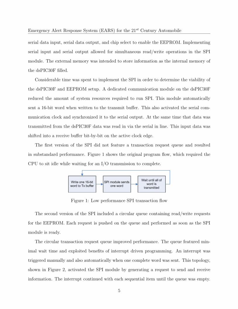
The first version of the SPI did not feature a transaction request queue and resulted
in substandard performance. Figure 1 shows the original program flow, which required the
CPU to sit idle while waiting for an I/O transmission to complete.
Figure 1: Low performance SPI transaction flow
The second version of the SPI included a circular queue containing read/write requests
for the EEPROM. Each request is pushed on the queue and performed as soon as the SPI
module is ready.
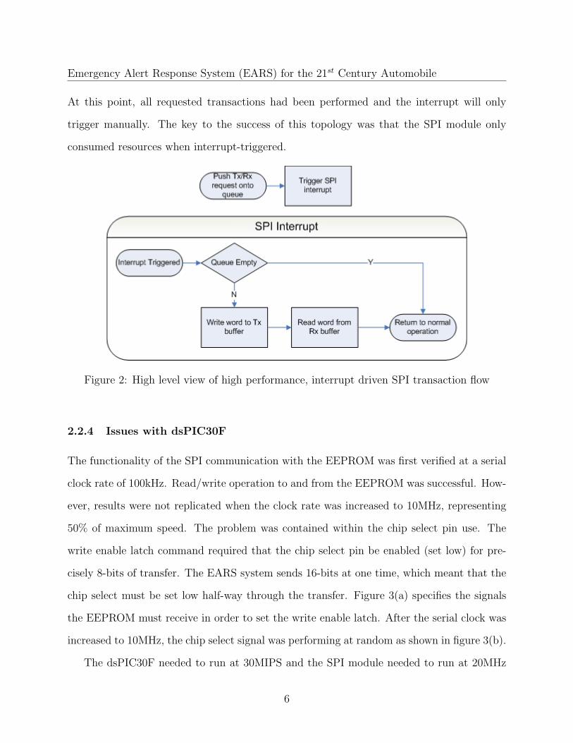
The circular transaction request queue improved performance. The queue featured min-
imal wait time and exploited benefits of interrupt driven programming. An interrupt was
triggered manually and also automatically when one complete word was sent. This topology,
shown in Figure 2, activated the SPI module by generating a request to send and receive
information. The interrupt continued with each sequential item until the queue was empty.
5
Emergency Alert Response System (EARS) for the 21st Century Automobile
At this point, all requested transactions had been performed and the interrupt will only
trigger manually. The key to the success of this topology was that the SPI module only
consumed resources when interrupt-triggered.
Figure 2: High level view of high performance, interrupt driven SPI transaction flow
2.2.4 Issues with dsPIC30F
The functionality of the SPI communication with the EEPROM was first verified at a serial
clock rate of 100kHz. Read/write operation to and from the EEPROM was successful. How-
ever, results were not replicated when the clock rate was increased to 10MHz, representing
50% of maximum speed. The problem was contained within the chip select pin use. The
write enable latch command required that the chip select pin be enabled (set low) for pre-
cisely 8-bits of transfer. The EARS system sends 16-bits at one time, which meant that the
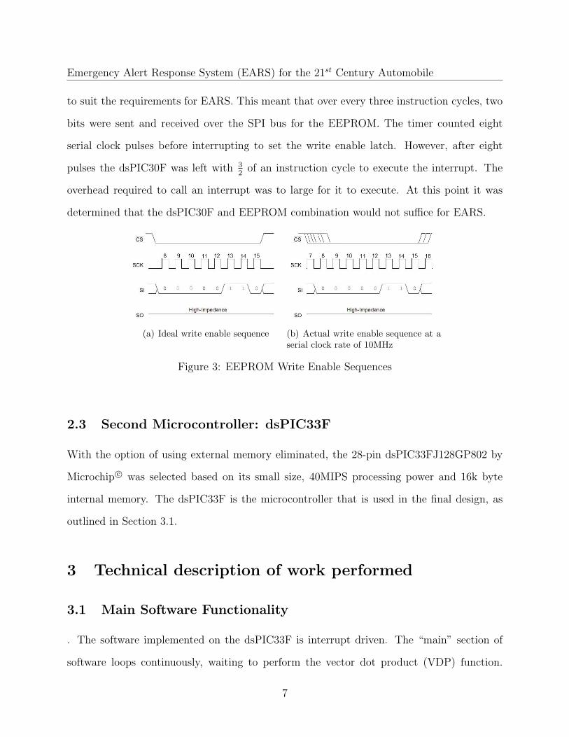
chip select must be set low half-way through the transfer. Figure 3(a) specifies the signals
the EEPROM must receive in order to set the write enable latch. After the serial clock was
increased to 10MHz, the chip select signal was performing at random as shown in figure 3(b).
The dsPIC30F needed to run at 30MIPS and the SPI module needed to run at 20MHz
6
Emergency Alert Response System (EARS) for the 21st Century Automobile
to suit the requirements for EARS. This meant that over every three instruction cycles, two
bits were sent and received over the SPI bus for the EEPROM. The timer counted eight
serial clock pulses before interrupting to set the write enable latch. However, after eight
pulses the dsPIC30F was left with 32
of an instruction cycle to execute the interrupt. The
overhead required to call an interrupt was to large for it to execute. At this point it was
determined that the dsPIC30F and EEPROM combination would not suffice for EARS.
(a) Ideal write enable sequence (b) Actual write enable sequence at aserial clock rate of 10MHz
Figure 3: EEPROM Write Enable Sequences
2.3 Second Microcontroller: dsPIC33F
With the option of using external memory eliminated, the 28-pin dsPIC33FJ128GP802 by
Microchip c© was selected based on its small size, 40MIPS processing power and 16k byte
internal memory. The dsPIC33F is the microcontroller that is used in the final design, as
outlined in Section 3.1.
3 Technical description of work performed
3.1 Main Software Functionality
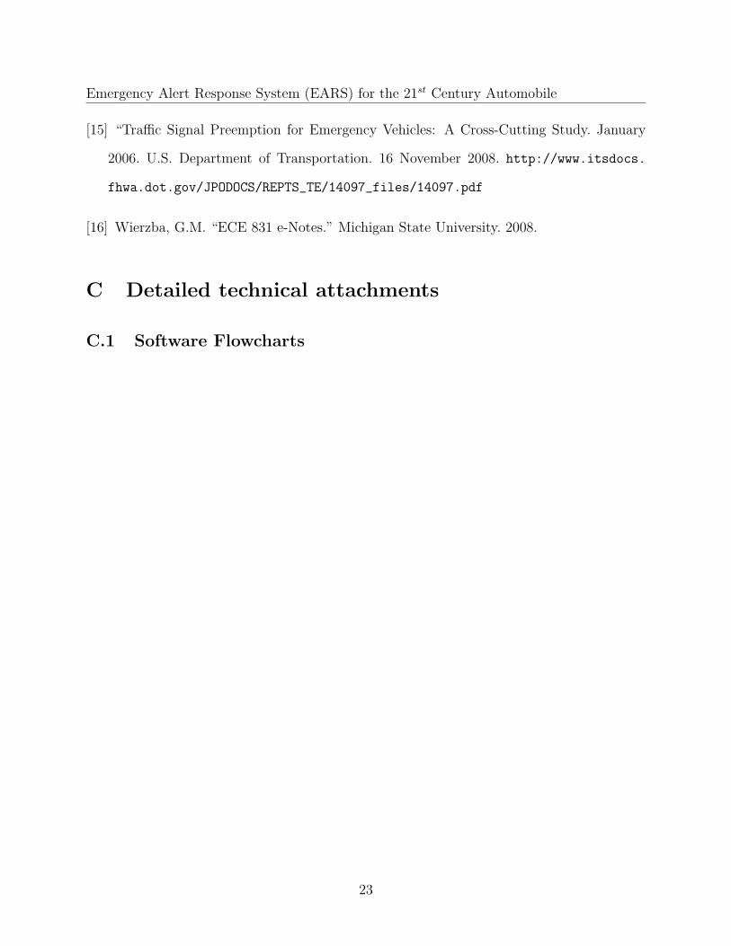
. The software implemented on the dsPIC33F is interrupt driven. The “main” section of
software loops continuously, waiting to perform the vector dot product (VDP) function.
7
Emergency Alert Response System (EARS) for the 21st Century Automobile
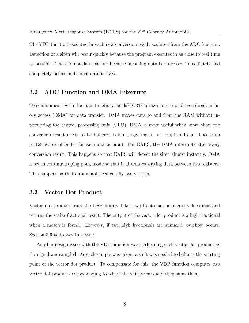
The VDP function executes for each new conversion result acquired from the ADC function.
Detection of a siren will occur quickly because the program executes in as close to real time
as possible. There is not data backup because incoming data is processed immediately and
completely before additional data arrives.
3.2 ADC Function and DMA Interrupt
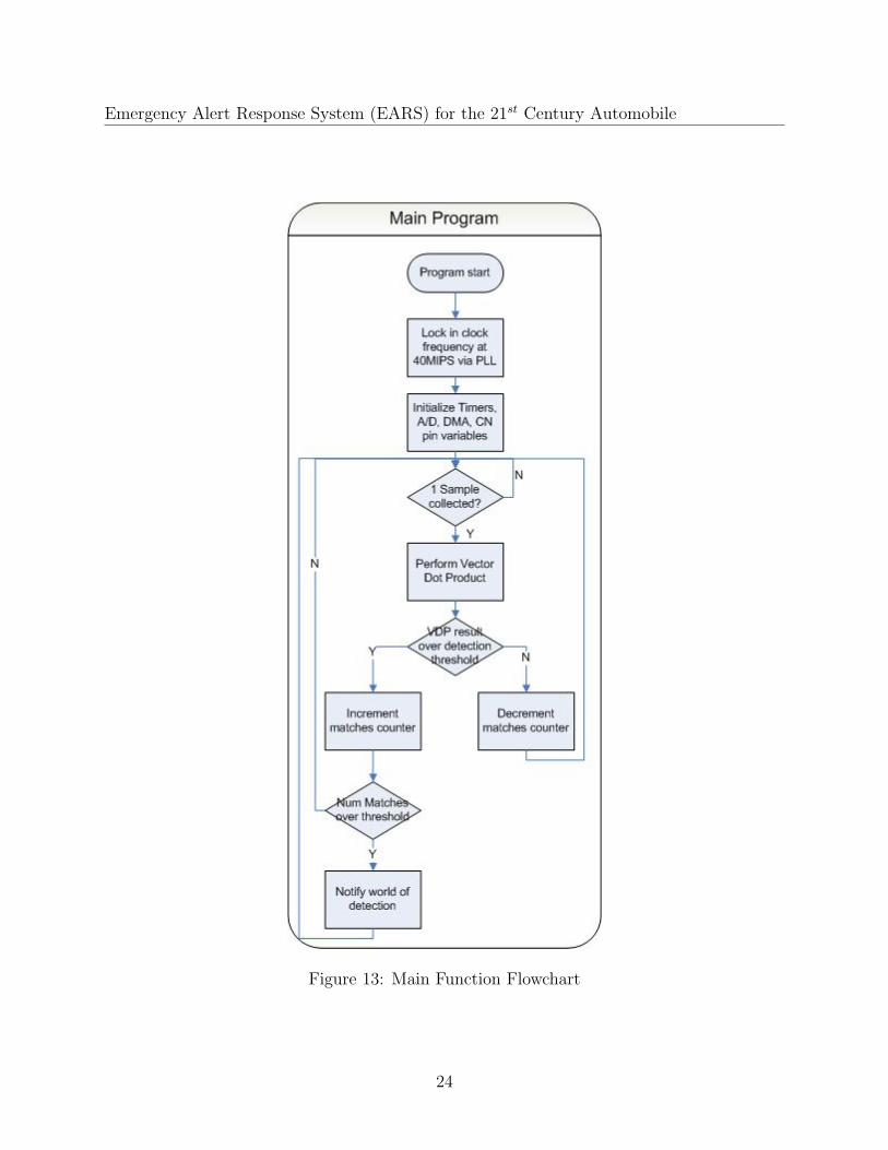
To communicate with the main function, the dsPIC33F utilizes interrupt-driven direct mem-
ory access (DMA) for data transfer. DMA moves data to and from the RAM without in-
terrupting the central processing unit (CPU). DMA is most useful when more than one
conversion result needs to be buffered before triggering an interrupt and can allocate up
to 128 words of buffer for each analog input. For EARS, the DMA interrupts after every
conversion result. This happens so that EARS will detect the siren almost instantly. DMA
is set in continuous ping pong mode so that it alternates writing data between two registers.
This happens so that data is not accidentally overwritten.
3.3 Vector Dot Product
Vector dot product from the DSP library takes two fractionals in memory locations and
returns the scalar fractional result. The output of the vector dot product is a high fractional
when a match is found. However, if two high fractionals are summed, overflow occurs.
Section 3.6 addresses this issue.
Another design issue with the VDP function was performing each vector dot product as
the signal was sampled. As each sample was taken, a shift was needed to balance the starting
point of the vector dot product. To compensate for this, the VDP function computes two
vector dot products corresponding to where the shift occurs and then sums them.
8
Emergency Alert Response System (EARS) for the 21st Century Automobile
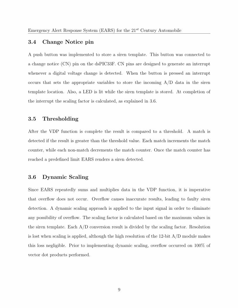
3.4 Change Notice pin
A push button was implemented to store a siren template. This button was connected to
a change notice (CN) pin on the dsPIC33F. CN pins are designed to generate an interrupt
whenever a digital voltage change is detected. When the button is pressed an interrupt
occurs that sets the appropriate variables to store the incoming A/D data in the siren
template location. Also, a LED is lit while the siren template is stored. At completion of
the interrupt the scaling factor is calculated, as explained in 3.6.
3.5 Thresholding
After the VDP function is complete the result is compared to a threshold. A match is
detected if the result is greater than the threshold value. Each match increments the match
counter, while each non-match decrements the match counter. Once the match counter has
reached a predefined limit EARS renders a siren detected.
3.6 Dynamic Scaling
Since EARS repeatedly sums and multiplies data in the VDP function, it is imperative
that overflow does not occur. Overflow causes inaccurate results, leading to faulty siren
detection. A dynamic scaling approach is applied to the input signal in order to eliminate
any possibility of overflow. The scaling factor is calculated based on the maximum values in
the siren template. Each A/D conversion result is divided by the scaling factor. Resolution
is lost when scaling is applied, although the high resolution of the 12-bit A/D module makes
this loss negligible. Prior to implementing dynamic scaling, overflow occurred on 100% of
vector dot products performed.
9
Emergency Alert Response System (EARS) for the 21st Century Automobile
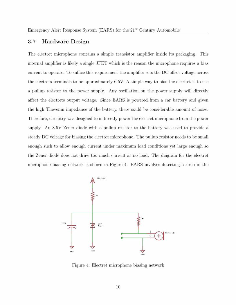
3.7 Hardware Design
The electret microphone contains a simple transistor amplifier inside its packaging. This
internal amplifier is likely a single JFET which is the reason the microphone requires a bias
current to operate. To suffice this requirement the amplifier sets the DC offset voltage across
the electrets terminals to be approximately 6.5V. A simple way to bias the electret is to use
a pullup resistor to the power supply. Any oscillation on the power supply will directly
affect the electrets output voltage. Since EARS is powered from a car battery and given
the high Thevenin impedance of the battery, there could be considerable amount of noise.
Therefore, circuitry was designed to indirectly power the electret microphone from the power
supply. An 8.5V Zener diode with a pullup resistor to the battery was used to provide a
steady DC voltage for biasing the electret microphone. The pullup resistor needs to be small
enough such to allow enough current under maximum load conditions yet large enough so
the Zener diode does not draw too much current at no load. The diagram for the electret
microphone biasing network is shown in Figure 4. EARS involves detecting a siren in the
Figure 4: Electret microphone biasing network
10
Emergency Alert Response System (EARS) for the 21st Century Automobile
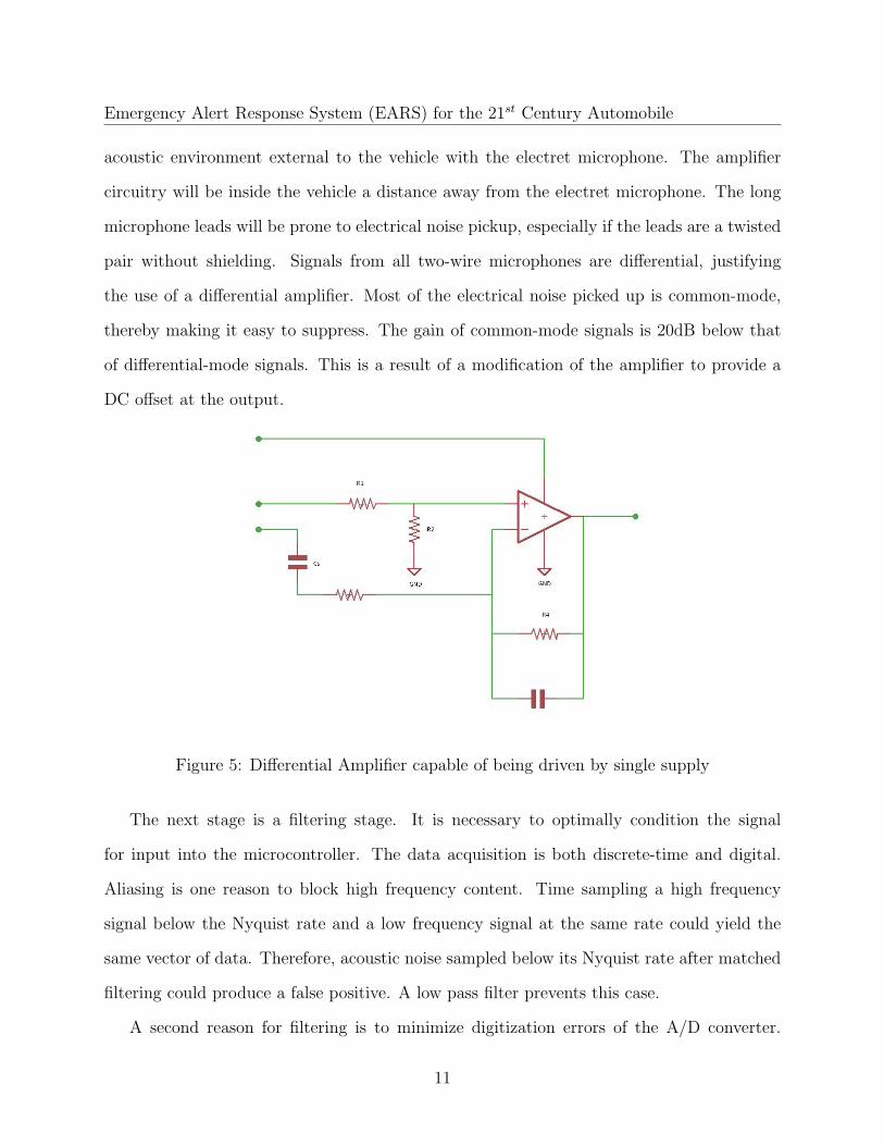
acoustic environment external to the vehicle with the electret microphone. The amplifier
circuitry will be inside the vehicle a distance away from the electret microphone. The long
microphone leads will be prone to electrical noise pickup, especially if the leads are a twisted
pair without shielding. Signals from all two-wire microphones are differential, justifying
the use of a differential amplifier. Most of the electrical noise picked up is common-mode,
thereby making it easy to suppress. The gain of common-mode signals is 20dB below that
of differential-mode signals. This is a result of a modification of the amplifier to provide a
DC offset at the output.
Figure 5: Differential Amplifier capable of being driven by single supply
The next stage is a filtering stage. It is necessary to optimally condition the signal
for input into the microcontroller. The data acquisition is both discrete-time and digital.
Aliasing is one reason to block high frequency content. Time sampling a high frequency
signal below the Nyquist rate and a low frequency signal at the same rate could yield the
same vector of data. Therefore, acoustic noise sampled below its Nyquist rate after matched
filtering could produce a false positive. A low pass filter prevents this case.
A second reason for filtering is to minimize digitization errors of the A/D converter.
11
Emergency Alert Response System (EARS) for the 21st Century Automobile
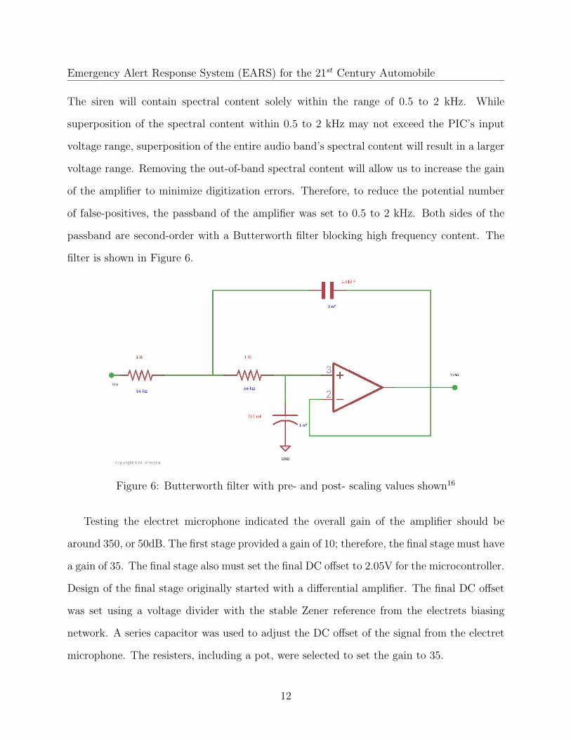
The siren will contain spectral content solely within the range of 0.5 to 2 kHz. While
superposition of the spectral content within 0.5 to 2 kHz may not exceed the PIC’s input
voltage range, superposition of the entire audio band’s spectral content will result in a larger
voltage range. Removing the out-of-band spectral content will allow us to increase the gain
of the amplifier to minimize digitization errors. Therefore, to reduce the potential number
of false-positives, the passband of the amplifier was set to 0.5 to 2 kHz. Both sides of the
passband are second-order with a Butterworth filter blocking high frequency content. The
filter is shown in Figure 6.
Figure 6: Butterworth filter with pre- and post- scaling values shown16
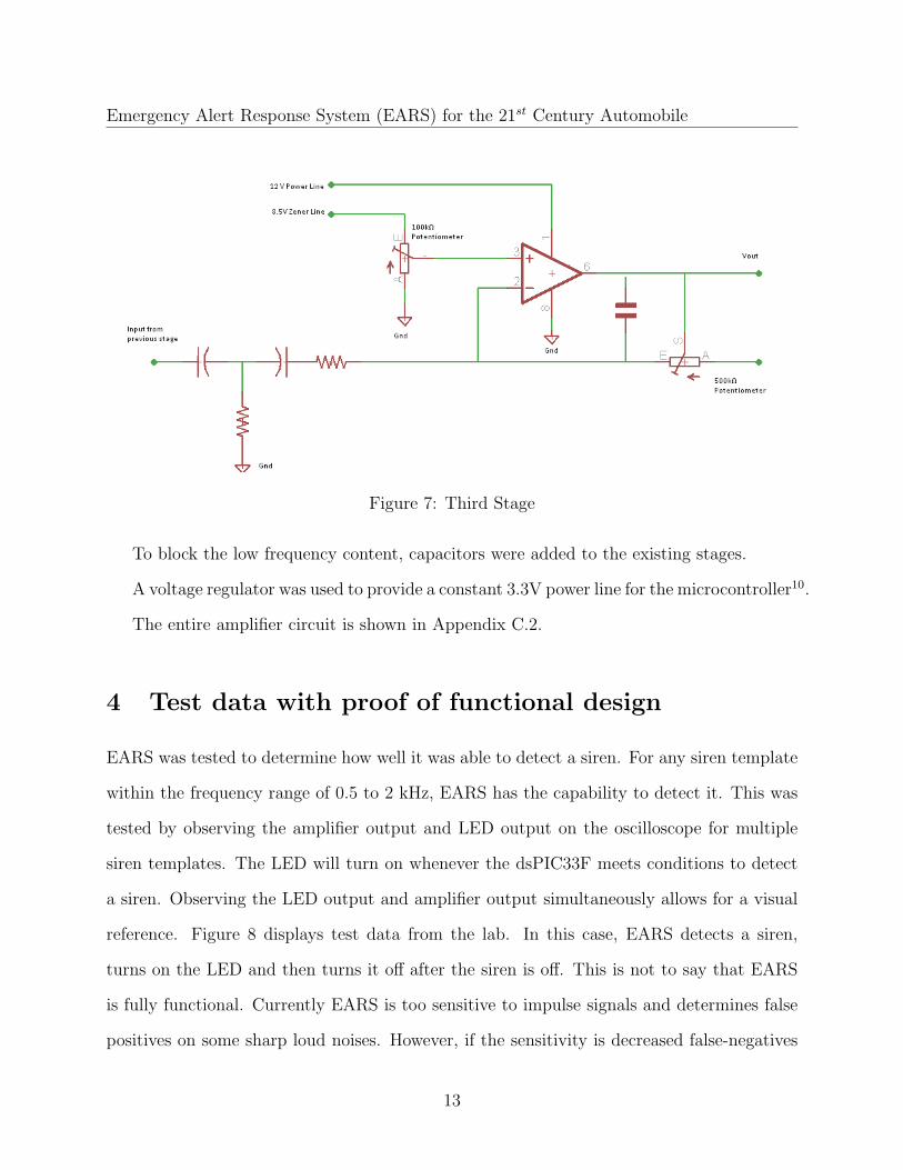
Testing the electret microphone indicated the overall gain of the amplifier should be
around 350, or 50dB. The first stage provided a gain of 10; therefore, the final stage must have
a gain of 35. The final stage also must set the final DC offset to 2.05V for the microcontroller.
Design of the final stage originally started with a differential amplifier. The final DC offset
was set using a voltage divider with the stable Zener reference from the electrets biasing
network. A series capacitor was used to adjust the DC offset of the signal from the electret
microphone. The resisters, including a pot, were selected to set the gain to 35.
12
Emergency Alert Response System (EARS) for the 21st Century Automobile
Figure 7: Third Stage
To block the low frequency content, capacitors were added to the existing stages.
A voltage regulator was used to provide a constant 3.3V power line for the microcontroller10.
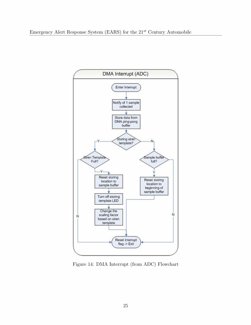
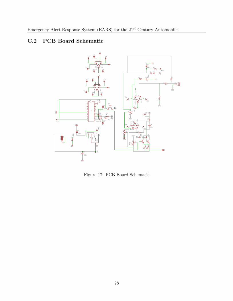
The entire amplifier circuit is shown in Appendix C.2.
4 Test data with proof of functional design
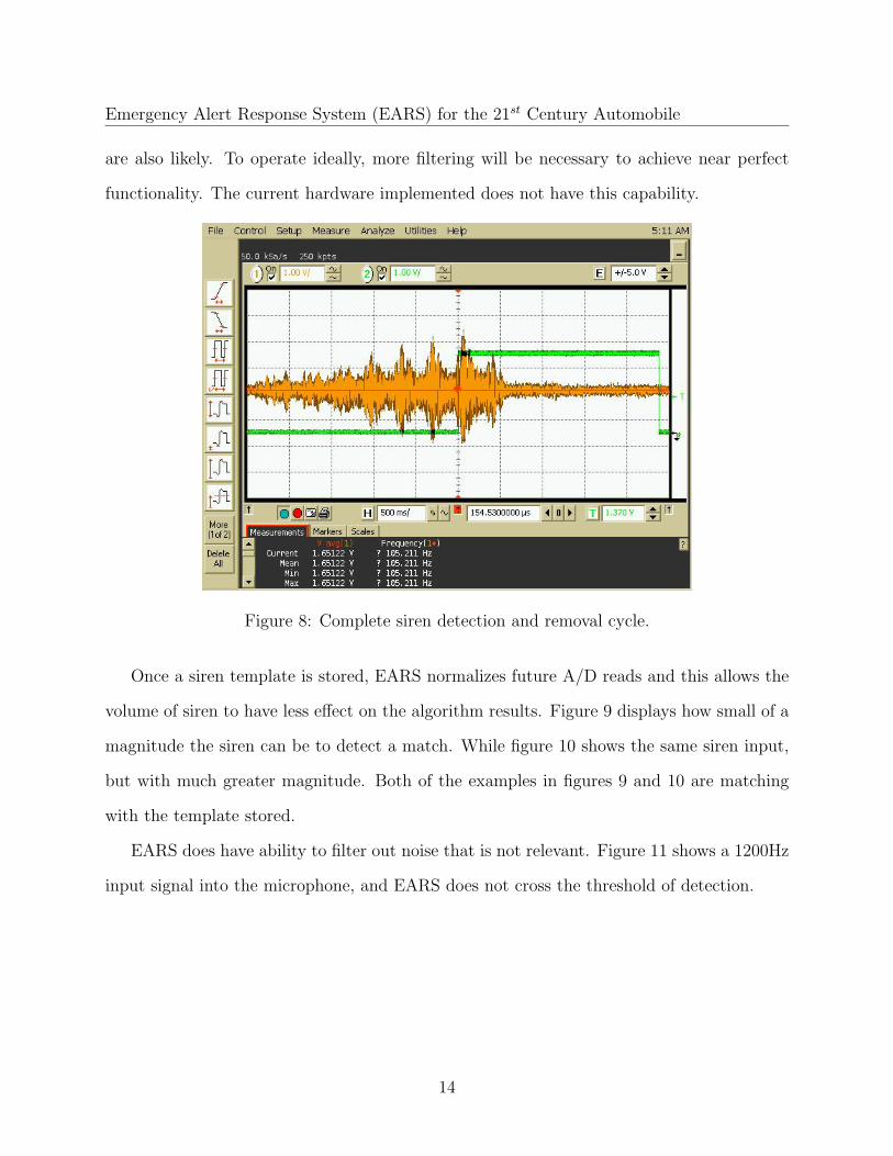
EARS was tested to determine how well it was able to detect a siren. For any siren template
within the frequency range of 0.5 to 2 kHz, EARS has the capability to detect it. This was
tested by observing the amplifier output and LED output on the oscilloscope for multiple
siren templates. The LED will turn on whenever the dsPIC33F meets conditions to detect
a siren. Observing the LED output and amplifier output simultaneously allows for a visual
reference. Figure 8 displays test data from the lab. In this case, EARS detects a siren,
turns on the LED and then turns it off after the siren is off. This is not to say that EARS
is fully functional. Currently EARS is too sensitive to impulse signals and determines false
positives on some sharp loud noises. However, if the sensitivity is decreased false-negatives
13
Emergency Alert Response System (EARS) for the 21st Century Automobile
are also likely. To operate ideally, more filtering will be necessary to achieve near perfect
functionality. The current hardware implemented does not have this capability.
Figure 8: Complete siren detection and removal cycle.
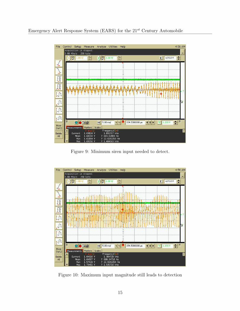
Once a siren template is stored, EARS normalizes future A/D reads and this allows the
volume of siren to have less effect on the algorithm results. Figure 9 displays how small of a
magnitude the siren can be to detect a match. While figure 10 shows the same siren input,
but with much greater magnitude. Both of the examples in figures 9 and 10 are matching
with the template stored.
EARS does have ability to filter out noise that is not relevant. Figure 11 shows a 1200Hz
input signal into the microphone, and EARS does not cross the threshold of detection.
14
Emergency Alert Response System (EARS) for the 21st Century Automobile
Figure 9: Minimum siren input needed to detect.
Figure 10: Maximum input magnitude still leads to detection
15

Emergency Alert Response System (EARS) for the 21st Century Automobile
Figure 11: 1200Hz input signal does not activate siren.
5 Final cost, schedule, summary and conclusions
5.1 Final Budget
Category Quantity Description / Part Number Cost
Main Processing 1 Microchip dsPIC33FJ128GP802 Microcontroller $5.88
Acoustics 1 Electret Micophone / MD9745APZ-F $1.01
Acoustics 1 Siren Template - iTunes App $1.06
Acoustics 2 Operational Amplifier / LF411CN $2.16
Power 1 3.3V Voltage regulator / LM2576T-3.3 $3.05
Housing 1 Display Box / 1591ETCL $12.30
Various - Other low power components (R, C, L) ≤ $5
Total ≤ $29.40
16
Emergency Alert Response System (EARS) for the 21st Century Automobile
5.2 Conclusion
The work on siren detection produced an algorithm and prototype that provides a foundation
for future work on the project. The team found that while matched filtering is easily imple-
mentable and provides reasonable detection rates, the computational and memory resources
are quite demanding.
The end result did not function optimally due to the large number of false positives. These
false positives could be the result of higher spectral content picked up by the amplifier and
aliased down in to the band that the siren template occupies. However this case is unlikely,
because the microphone amplifier was band limited to prevent this. Another possibility is
that the ambient acoustic noise picked up when recording the template is matching with the
ambient acoustic noise present in the testing environment. This would be a more difficult case
to reject, as it would require recording the siren template in a low noise recording studio.
Simple thresholding on the matched filter output is used to determine whether a siren is
present. If the Matlab algorithm was used, then an autocorrelation of the output could
be performed and the distance between peaks would be compared to the siren templates
fundamentals period. Only when the spacing was similar would a siren be detected. This
works well in Matlab, however is too computationally intensive to implement in the PIC
microcontroller used. This leads to the opportunity for future work on the project: alternate
hardware could be used to implement the more advanced algorithm to improve detection
rates. The project was accomplished well under budget, further justifying the possibility of
future work.
17
Emergency Alert Response System (EARS) for the 21st Century Automobile
A Technical roles, responsibilities, and work accom-
plished
A.1 Don VanderLaan
Dons technical work included theoretical justification for matched filtering and design of the
analog circuitry required to interface the microphone with the microcontroller digitizer.
Theoretical simulation of the matched filtering technique was done in Matlab. A siren
audio file was used as the template for matching. Then, a superposition of the template and
various noise profiles was used to see if simple matched filtering work. Various distortions on
the input were also tried, to further determine the algorithms robustness. Tested distortions
include Doppler shift and various fade in and out and their combinations.
Simple matched filtering worked sufficiently for the non-distorted case, but the following
improvements were made to the algorithm: The fundamental frequency of the template
was determined by the inverse of the distance between peaks in an autocorrelation of the
template. An autocorrelation is computed from the output of the simple matched filtering,
and if the peaks in this vector are spaced the same distance as the period of the fundamental
frequency of the template, the siren is deemed present. This resulted in superior detection
for all inputs.
Don also designed the microphone amplifier. The amplifier was used to interface an
electret microphone to the microcontrollers analog to digital converter. The overall gain of
the amplifier needed to be 350, therefore two gain stages were used. A low-pass Butterworth
filter was designed using G. M. Wierzbas procedure of magnitude and frequency scaling a
normalized Butterworth filter.
The electrets bias network included a zener held below the supply to provide a stable DC
voltage for biasing the electret microphone. This will reduce the susceptibility of the design
18
Emergency Alert Response System (EARS) for the 21st Century Automobile
to oscillations on the power supply.
A.2 Jeremy Konz
As one of two computer engineering students on the team, the technical role that Jeremy held
was highly based on software design. He was tasked with creation of the SPI communication
bus module for the dsPIC30F. Jeremy created a SPI function library to communicate with
the EEPROM. After writing the original SPI implementation, he wrote an alternative design
which featured a circular transaction request queue. The second version of the module
decreased use of system resources drastically. However, SPI module testing ultimately led
to the consideration of a new microcontroller for EARS.
For the dsPIC33F Jeremy wrote the main functionality and program flow with the help
of Natalie and Tom. This included memory management, change notice interrupts for push
buttons, and PLL control to achieve 40MIPS operation. Jeremy is the main author of main.c
and common.h, included in Appendix C. He was also involved with implementing dynamic
scaling which eliminated overflow.
A.3 Natalie Hannon
Natalie was responsible for data acquisition. This required knowledge of analog to digital
conversion (ADC) for interpretation of external audio noise by the dsPIC. She was the main
author of adc.c, included in Appendix C. She learned how to configure individual registers
within the A/D module to set reference voltages, configure data types and determine function
control. The ADC function for the dsPIC30F was interrupt-driven, requiring a separate ISR
to communicate with the main code. The switch from the dsPIC30F to the dsPIC33F
required her to re-write adc.c to use direct memory access (DMA). She learned how to
configure the DMA buffer to interrupt after every conversion result to achieve real time
19
Emergency Alert Response System (EARS) for the 21st Century Automobile
operation.
As part of the software team, Natalie assisted in debugging code. She looked at data
and interpreted the validity of the results and tested the ADC function for accuracy. She
worked with Jeremy and Tom to design the program flow, including the structure of the
main function, ADC and VDP functions.
A.4 Tom Aprik
Toms contribution to the project involved developing code for the vector dot product func-
tion. He assisted with the overall programming for the skeleton code of the microcontroller.
He also assisted in debugging all portions of the code, include the SPI, analog to digital
conversion, external oscillator, and DMA interrupt. The SPI portion was coded by Jeremy
and then tested and debugged by all group members, including Tom. The analog to digital
conversion was coded by Natalie and then debugged by Natalie, Jeremy, and Tom. The
integration of the external oscillator was done by Tom and tested by Jeremy. After weeks
of testing and much deliberation, it was decided by the team members that a different PIC
was needed to better suit the needs of the project. With the new microcontroller the SPI
and external oscillator were omitted from the project. The interrupt system had to be re-
written for the new microcontroller as well. Tom assisted with rewriting all the parts to work
correctly with the new microcontroller. Tom was also in charge of designing the complete
layout of the circuitry in Eagle and creating the PCB for the final display.
20

Emergency Alert Response System (EARS) for the 21st Century Automobile
(a) Don VanderLaan (b) Jeremy Konz (c) Natalie Hannon (d) Tom Aprik
Figure 12: Team Members
B Literature and website references
References
[1] “Crash Avoidance Metrics Partnership. December 2002. National Highway Traffic Safety
Administration. 16 November 2008. http://www.nrd.nhtsa.dot.gov/pdf/nrd-12/
CAMPS.pdf
[2] “dsPIC30F Digital Signal Controllers” Microchip. 2008. 04 Nov 2008. http://ww1.
microchip.com/downloads/en/DeviceDoc/dspbrochure_70095G.pdf
[3] “Emergency Vehicle Safety Initiative. August 2004. FEMA. 16 November 2008. http:
//www.usfa.dhs.gov/downloads/pdf/publications/fa-272.pdf
[4] Grimm, Don. “DSRC: An International Perspective. 2 May 2008. Online PowerPoint.
General Motors. 16 November 2008. http://www.acma.gov.au/webwr/_assets/main/
lib310662/23futurebandwidthreqirementsforitspart2.pdf
[5] Holstege, Sean. “GM shows off latest smart-car technology in S.F. Oakland Tribune.
7 November 2005. SIRS BNET. 16 November 2008. http://findarticles.com/p/
articles/mi_qn4176/is_20051107/ai_n15767653
21

Emergency Alert Response System (EARS) for the 21st Century Automobile
[6] “Intelligent Transportation Systems: Research and Innovative Technology Administra-
tion. 2008. U.S. Department of Transportation. 16 November 2008. http://www.its.
dot.gov/index.htm
[7] “Intelligent Vehicle Initiative. 2008. U.S. Department of Transportation. 16 November
2008. http://www.its.dot.gov/ivi/ivihf/index.html
[8] “Microchip dsPIC30F3014/4013 Data Sheet” Microchip. 2008. 04 Nov 2008. http://
ww1.microchip.com/downloads/en/DeviceDoc/70138F.pdf
[9] “Microchip dsPIC33FJ32GP302/304, dsPIC33FJ64GPX02/X04, and
dsPIC33FJ128GPX02/X04 Data Sheet” Microchip. 2008. 04 Nov 2008. http:
//www.microchip.com/wwwproducts/Devices.aspx?dDocName=en532298
[10] “National Semiconductor LM2576 Data Sheet” National Semiconductor. 2008. 01 Nov
2008. http://www.national.com/ds/LM/LM2576.pdf
[11] “National Statistics. Fatality Analysis Reporting System (FARS) Encyclopedia. 16
November 2008. http://www-fars.nhtsa.dot.gov/Main/index.aspx
[12] Murray, Charles J. “GM Shows off Safety Technology. 2 June 2008. Design
News. 16 November 2008. http://www.designnews.com/article/46449-GM_Shows_
off_Safety_Technology.php
[13] Perel, Michael. “IVI Human Factors Research. 12 January 2004. U.S. Department of
Transportation. Online PowerPoint. 16 November 2008. http://www.its.dot.gov/ivi/
ivihf/docs/IVI_HF.ppt
[14] Resendes, Raymond. “Intelligent Vehicle Initiative. U.S. Department of Transportation.
Online PowerPoint. 16 November 2008. http://ivsource.net/public/ppt/021001_
USIVI-Resendes.ppt
22
Emergency Alert Response System (EARS) for the 21st Century Automobile
[15] “Traffic Signal Preemption for Emergency Vehicles: A Cross-Cutting Study. January
2006. U.S. Department of Transportation. 16 November 2008. http://www.itsdocs.
fhwa.dot.gov/JPODOCS/REPTS_TE/14097_files/14097.pdf
[16] Wierzba, G.M. “ECE 831 e-Notes.” Michigan State University. 2008.
C Detailed technical attachments
C.1 Software Flowcharts
23
Emergency Alert Response System (EARS) for the 21st Century Automobile
Figure 13: Main Function Flowchart
24
Emergency Alert Response System (EARS) for the 21st Century Automobile
Figure 14: DMA Interrupt (from ADC) Flowchart
25

Emergency Alert Response System (EARS) for the 21st Century Automobile
Figure 15: Vector Dot Product Function Flowchart
26

Emergency Alert Response System (EARS) for the 21st Century Automobile
Figure 16: Rescale Function Flowchart
27
Emergency Alert Response System (EARS) for the 21st Century Automobile
C.2 PCB Board Schematic
Figure 17: PCB Board Schematic
28
Emergency Alert Response System (EARS) for the 21st Century Automobile
Listing 1: Project Code for dsPIC33F
1 /∗ F i l e : main2 ∗3 ∗Written by : ECE 480 Design Team 9 , Fa l l 084 ∗5 ∗Contains : Main funct ion , a l s o t imer i n i t i a l i z a t i o n , change no t i c e in t e r rupt ,
r e s c a l i n g funct ion , Vector Dot Product6 ∗/78 #inc lude ”common . h”9 #inc lude ”adc . c”
1011 // S e l e c t I n t e r na l FRC at POR12 FOSCSEL(FNOSC FRC) ;13 // Enable Clock Switching and Conf igure14 FOSC(FCKSM CSECMD & OSCIOFNC OFF ) ;15 FWDT(FWDTEN OFF) ; // Watchdog Timer Enabled/ d i s ab l ed1617 i n t main ( )18 {19 TRISB = 0x8000 ; // s e t up the B port as a l l outputs20 CORCONbits .PSV = 1 ; // enable Program Space V i s i b i l i t y212223 /∗∗∗∗∗∗∗∗∗∗∗∗∗∗∗ Functions to s e t up hardware ∗∗∗∗∗∗∗∗∗∗/24 CNinit ( ) ; // i n i t i a l i z e the change no t i c e p ins25 TMRinit ( ) ; // i n i t i a l i z e the t imers26 CLOCKinit ( ) ; // s e t the c l o ck f requency to 40MIPS2728 ADC() ; // i n i t i a l i z e the A/D29 DMA() ; // i n i t i a l i z e the DMA3031 /∗∗∗∗∗∗∗∗∗∗∗∗∗∗ Var iab le i n i t i a l i z a t i o n ∗∗∗∗∗∗∗∗∗∗∗∗∗∗∗/32 ADCstore = &sample [ 0 ] ; // i n i t i a l i z e the l o c a t i o n to s t o r e the ADC
in f o as33 // the out s id e sample34 ind = 0 ;35 RunFi lter = 0 ;36 matches = 0 ;37 MATCH LED = 0 ;383940 whi l e (1 ) /∗ code execut ion − i n t e r r up t dr iven ∗/41 {42 i f ( RunFi lter ) /∗ f l a g s e t upon r e c e i v i n g new sample ∗/43 {44 r e s u l t = VDP( ) ; // perform vec tor dot product matched
f i l t e r i n g45 RunFi lter = 0 ; //Reset f l a g to get more ADC data4647 // i f the r e s u l t i s negat ive , take the 2 s complement so the
29
Emergency Alert Response System (EARS) for the 21st Century Automobile
magnitude can be eva luated48 i f ( r e s u l t >= 0b1000000000000000 )49 {50 r e s u l t = ( r e s u l t ˆ 0xFFFF) + 1 ;51 }5253 i f ( ( r e s u l t >= 0b0001000000000000 ) && ( matches < 300) )
// i f r e s u l t i s above thr e sho ld54 {55 matches += 10 ; // increment
the matches counter56 }57 e l s e i f ( ( r e s u l t < 0b1000000000000000 ) && ( matches > 0) )58 {59 matches−−; //
decrement the matches counter6061 }6263 i f ( matches >= MATCHTHRESHOLD) // d i sp l ay a match to the world64 {65 MATCH LED = 1 ; // turn on LED6667 // t imer i s s e t to turn o f f the match l ed a f t e r 1
second . . .68 // assuming i t i s not r e s e t again here on the next
match69 TMR5 = 0x00 ; // Clear 32−
b i t Timer (msw)70 TMR4 = 0x00 ; // Clear 32−
b i t Timer ( lsw )71 T4CONbits .TON = 1 ; // Star t Timer72 }73 }74 }75 return 0 ;76 }7778 void CLOCKinit ( void )79 { /∗ Name : CLOCKinit ( c l o ck i n i t i a l i z a t i o n )80 ∗ Function : To s e t up the c l o ck to ach ieve maximum speed81 ∗ Explanation : This s tep i s nece s sa ry in order to get 40MIPS operat i on .82 ∗ The onboard RC o s c i l l a t o r i s sent through the PLL to get t h i s
speed .83 ∗84 ∗ Taken from http ://ww1. microchip . com/downloads/en/DeviceDoc
/70216B. pdf85 ∗ Page 2286 ∗/8788 // Conf igure PLL pr e s c a l e r , PLL po s t s c a l e r , PLL d i v i s o r
30
Emergency Alert Response System (EARS) for the 21st Century Automobile
89 PLLFBD = 41 ; // M = 4390 CLKDIVbits .PLLPOST=0; // N1 = 291 CLKDIVbits .PLLPRE=0; // N2 = 29293 // I n i t i a t e Clock Switch to I n t e r na l FRC with PLL (NOSC = 0b001 )94 builtin write OSCCONH (0 x01 ) ;95 builtin write OSCCONL (0 x01 ) ;9697 // Wait f o r Clock switch to occur98 whi l e (OSCCONbits .COSC != 0b001 ) ;99
100 // Wait f o r PLL to lock101 whi l e (OSCCONbits .LOCK!=1) {} ;102 }103104 f r a c t i o n a l res1 , r e s2 ; // r e s u l t s f r a c t i o n a l s from the two ha lve s o f the VDP105106 f r a c t i o n a l VDP( void )107 {108 /∗ Name : VDP ( vec to r dot product )109 ∗ Function : To perform a s i n g l e vec to r dot product110 ∗ Returns : The f r a c t i o n a l r e s u l t o f the VDP matched f i l t e r i n g , ranging
from −1 to 1111 ∗ Explanation : As long as the s i r e n template i s not cu r r en t l y being
s to r ed112 ∗ we w i l l use the sample and the s i r e n template ar rays and
c a l c u l a t e the113 ∗ VDP. This r e s u l t w i l l range between −1 and 1 in a s igned 16−
b i t f r a c t i o n a l114 ∗ because o f the s c a l i n g func t i on . The VectorDotProduct was
inc luded in the115 ∗ DSP l i b r a r y by microchip , i t i s f a s t .116 ∗/117118 i f ( ! s t o r i n g s i r e n )119 {120 i f (ADCstore == &sample [ 0 ] ) // i f the l a t e s t sample i s the
beg inning o f the sample bu f f e r121 { // only
one VDP i s needed122 re turn VectorDotProduct (SAMPLE SIZE, &sample [ 0 ] , &
s i r en t emp l a t e [ 0 ] ) ;123 }124 e l s e125 {126 re s1 = VectorDotProduct (SAMPLE SIZE−ind , &sample [ ind ] ,
&s i r en t emp l a t e [ 0 ] ) ;127 r e s2 = VectorDotProduct ( ind , &
sample [ 0 ] , &s i r en t emp l a t e [ SAMPLE SIZE − ind ] );
128 re turn ( r e s1 + re s2 ) ;
31
Emergency Alert Response System (EARS) for the 21st Century Automobile
129 }130 }131 return NULL;132 }133134 void CNinit ( void )135 {136 /∗ Name : CNinit ( change no t i c e i n i t i a l i z a t i o n )137 ∗ Function : To s e t up the change no t i c e pin138 ∗ Explanation : The change no t i c e pin i s used to de t e c t a button pr e s s139 ∗/140141 CNEN1bits .CN0IE = 1 ; // enable the i n t e r r up t on the CN11 pin142 CNPU1bits .CN0PUE = 1 ; // enable the i n t e r n a l pu l l−up r e s i s t o r f o r
button143 IEC1bits .CNIE = 1 ; // enable the CN in t e r r up t s144 IFS1b i t s .CNIF = 0 ; // c l e a r CN in t e r r up t f l a g145 }146147 void TMRinit ( void )148 { /∗ Name : TMRinit ( t imer i n i t i a l i z a t i o n )149 ∗ Function : To s e t up the t imer that keeps the match LED on f o r150 ∗ an extended per iod o f time151 ∗ Explanation : This t imer c on t r o l s the matched l ed . S ince we want the152 ∗ LED to be on f o r 5 seconds , the t imer needs to be 32−b i t s153 ∗/154155 T5CONbits .TON = 0 ; // Stop any 16−b i t Timer3 opera t ion156 T4CONbits .TON = 0 ; // Stop any 16/32− b i t Timer3 opera t i on157 T4CONbits . T32 = 1 ; // Enable 32−b i t Timer mode158 T4CONbits .TCS = 0 ; // S e l e c t i n t e r n a l i n s t r u c t i o n cy c l e c l o ck159 T4CONbits .TGATE = 0 ; // Disab le Gated Timer mode160 T4CONbits .TCKPS = 0b00 ; // S e l e c t 1 : 1 P r e s c a l e r161 TMR5 = 0x00 ; // Clear 32−b i t Timer (msw)162 TMR4 = 0x00 ; // Clear 32−b i t Timer ( lsw )163 PR5 = 0x04c4 ; // Load 32−b i t per iod value (msw)164 PR4 = 0xb400 ; // Load 32−b i t per iod value ( lsw )165 IPC7bits . T5IP = 0x01 ; // Set Timer3 In t e r rup t P r i o r i t y Leve l166 IFS1b i t s . T5IF = 0 ; // Clear Timer3 In t e r rupt Flag167 IEC1bits . T5IE = 1 ; // Enable Timer3 i n t e r r up t168 T4CONbits .TON = 0 ; // Star t 32−b i t Timer169 }170171 void a t t r i b u t e ( ( i n t e r r u p t , a u t o p s v ) ) CNInterrupt ( void )172 { /∗ Name : CNInterrupt173 ∗ Function : This i n t e r r up t execute s upon any d i g i t a l change on a CN pin174 ∗ Explanation : This i n t e r r up t w i l l execute when any CN button i s pre s sed
. The i n t e r r up t must determine which pin ,175 ∗ and execute the accord ing command , e i t h e r s t o r e a s i r e n or
ackgnowledge one176 ∗/
32
Emergency Alert Response System (EARS) for the 21st Century Automobile
177178 // t h i s case i s the s t o r e s i r e n button179 i f (PORTAbits .RA4 == 0) // i f the CN11 pin has
indeed been pre s s ed180 {181 PORTBbits .RB8 = 1 ; // turn on LED
to show s t o r i n g as template182 ADCstore = &s i r en t emp l a t e [ 0 ] ; // t e l l the ADC to s t o r e the
s h i t in the template183 s t o r i n g s i r e n = 1 ;184 s h i f t s c a l e = 0 ;185 s c a l a r = 1 ;186 }187188 IFS1b i t s .CNIF = 0 ; // c l e a r i n t e r r up t f l a g189 }190191 void a t t r i b u t e ( ( i n t e r r u p t , shadow ) ) T5Inter rupt ( void )192 { /∗ Name : T5Inter rupt193 ∗ Function : This i n t e r r up t execute s when the 32−b i t t imer counts to the
s p e c i f i e d amount194 ∗ Explanation : The f u n c t i o n a l i t y o f t h i s t imer i s to turn o f f the l ed
and r e l ay i nd i c a t i n g a match195 ∗ a f t e r a s p e c i f i e d amount o f time .196 ∗/197198 MATCH LED = 0 ; // turn o f f LED199 T5CONbits .TON = 0 ; // Disab le Timer200 IFS1b i t s . T5IF = 0 ; // Clear Timer1 i n t e r r up t f l a g201 }202203 void r e s c a l e ( void )204 { /∗ Name : r e s c a l e205 ∗ Function : This func t i on w i l l a l t e r the s c a l i n g f a c t o r accord ing to the
cur rent s i r e n template206 ∗ Explanation : The s c a l i n g f a c t o r must be changed accord ing to the
template so that no over f l ow occurs .207 ∗ The s c a l i n g ensure s that the r e s u l t from the VDP w i l l range
between −1 and 1 . I t f unc t i on s by208 ∗ running a VDP with the vec to r which w i l l ach i eve the maximum
VDP r e s u l t and then s c a l i n g209 ∗ every s u c c e s s i v e sample based on that . This i s done by
watching f o r over f low , i f i t i s about to210 ∗ occur , then mult ip ly the s c a l i n g f a c t o r by 2 and d iv i d i ng the
VDP r e s u l t by 2 .211 ∗/212 i n t i ;213 f r a c t i o n a l vdp res = 0 ;214 s c a l a r = 4 ;215216 // turn o f f the A/D so that i t does not i n t e r r up t t h i s operat i on and ove rwr i t e
33

Emergency Alert Response System (EARS) for the 21st Century Automobile
sample va lue s217 AD1CON1bits .ADON = 0 ; // turn o f f both A/D and timer3218 T3CONbits .TON = 0 ;219220 f o r ( i = 0 ; i < SAMPLE SIZE ; i++)221 {222 // determine whether p o s i t i v e or negat ive maximum should be used223 i f ( s i r en t emp l a t e [ i ] > 0)224 {225 sample [ i ] = 0x7FFF ; // p o s i t i v e maximum226 }227 e l s e228 {229 sample [ i ] = 0x8000 ; // negat ive maximum230 }231232 //add the new value233 vdp res += ( sample [ i ] ∗ s i r en t emp l a t e [ i ] ) / s c a l a r ;234235 // i f the vdp r e su l t i s above 0 . 5 , then over f l ow i s p o s s i b l e and must
s c a l e a c co rd ing ly236 i f ( vdp res > 0b0100000000000000 )237 {238 s c a l a r = s c a l a r << 1 ; // mult ip ly by 2239 vdp res = vdp res / 2 ; // d iv id e by 2240 }241 }242243 // resume normal f u n c t i o n a l i t y o f A/D244 AD1CON1bits .ADON = 1 ; // turn on both A/D and timer3245 T3CONbits .TON = 1 ;246 }
34
Emergency Alert Response System (EARS) for the 21st Century Automobile
Listing 2: Project Code for dsPIC33F
1 /∗ F i l e : adc . c2 ∗3 ∗Written by : ECE 480 Design Team 9 , Fa l l 084 ∗5 ∗Contains : f unc t i on d e s c t r i p t i o n s to use the analog to d i g i t a l port o f the
dsPIC33FJ128GP8026 ∗/789
10 f r a c t i o n a l RegisterA [ADC NUM SAMP] a t t r i b u t e ( ( space (dma) ) ) ; // pingpong bu f f e r f o r DMA
11 f r a c t i o n a l RegisterB [ADC NUM SAMP] a t t r i b u t e ( ( space (dma) ) ) ; // pingpong butte r f o r DMA
1213 void ADC( void )14 {15 /∗ Name : ADC16 ∗ Function : To i n i t i a l i z e the analog to d i g i t a l port and timer3 , which
d r i v e s sampling ra t e17 ∗ Explanation : The appropr ia te c on f i g u r a t i on r e g i s t e r s are s e t to
ach ieve the s e t t i n g s we are l ook ing f o r .18 ∗/1920 AD1CON1bits .ADON = 0 ; //make sure ad i s o f f21 AD1CON1bits .ADSIDL = 0 ; // cont inue opera t ion in i d l e mode22 AD1CON1bits .ADDMABM = 1 ; //DMA wr i t t en in order o f conver s i on23 AD1CON1bits .AD12B = 1 ; //12− b i t va lue s24 AD1CON1bits .FORM = 3 ; // f r a c t i o n a l = 2 , i n t e g e r = 025 AD1CON1bits .SSRC = 2 ; // choose t imer3 to sample26 AD1CON1bits .ASAM = 1 ; // auto sample2728 AD1CON2bits .VCFG = 0 ; // use Avdd and Avss29 AD1CON2bits .CSCNA = 0 ; //no scanning30 AD1CON2bits .CHPS = 0 ; // channel 0 only31 AD1CON2bits . SMPI = 0 ; // i n t e r r up t a f t e r every sample32 AD1CON2bits .BUFM = 0 ; // s t a r t f i l l i n g at s t a r t every time33 AD1CON2bits .ALTS = 0 ; // always use sample A from channel3435 AD1CON3bits .ADRC = 0 ; // use system c lock f o r AD conv c l o ck36 AD1CON3bits .ADCS = 26 ; //668 ns /25 ns = 26 .72 , where Tcy = 1/(80 MHz/2)
= 25ns37 //Want to minimize
ADCS f o r f a s t e r A/D
38 //MIPS = Fosc /2 = Fcy= 80 MHz/2 = 40MIPS
39 //Tad = Tcy∗(ADCS+1) =1600 ns > 668 ns
35
Emergency Alert Response System (EARS) for the 21st Century Automobile
l im i t40 //ADC Conversion Time
f o r 12−b i t Tc=14∗Tad = 22 .4 us
414243 AD1CHS0bits .CH0NA = 0 ; // use Vref−44 AD1CHS0bits .CH0SA = 11 ; // use AN114546 AD1PCFGL = 0xFFFF; // s e t up AN11 as analog input , a l l
r e s t d i g i t a l47 AD1PCFGLbits .PCFG11 = 0 ; // AN11 as Analog Input4849 //Timer350 TMR3 = 0x0000 ;51 PR3 = TMR SAMP COUNT; // counts o f how long to count un t i l new sample
i s taken52 IFS0b i t s . T3IF = 0 ;53 IEC0bits . T3IE = 0 ;5455 // Clear the A/D in t e r r up t f l a g b i t56 IFS0b i t s .AD1IF = 0 ;5758 // Set the A/D in t e r r up t enable b i t59 IEC0bits .AD1IE = 0 ;6061 //Turn on the A/D conver t e r62 AD1CON1bits .ADON = 1 ;6364 // Star t Timer 365 T3CONbits .TON = 1 ;66 }6768 void DMA ( void )69 {70 /∗ Name : DMA71 ∗ Function : To i n i t i a l i z e the Dynamic Memory Access72 ∗ Explanation : The c on f i gu r a t i on r e g i s t e r s are s e t to enag l e c o r r e c t
s t o r i n g o f the A/D samples through the DMA module73 ∗/7475 DMA0CONbits . SIZE = 0 ; // t r a n s f e r in words76 DMA0CONbits .DIR = 0 ; // read from pe r i ph e r a l to SRMA77 DMA0CONbits .HALF = 0 ; // i n i t i a t e i n t e r r up t when a l l i s t r a n s f e r r e d78 DMA0CONbits .NULLW = 0 ; //no nu l l data wr i t e79 DMA0CONbits .AMODE = 0 ; // r e g i s t e r i n d i r e c t with post−increment
addre s s ing80 DMA0CONbits .MODE = 2 ; // cont inuous ping pong mode8182 DMA0REQ = 13 ; // t r i g g e r on ADC183
36
Emergency Alert Response System (EARS) for the 21st Century Automobile
84 DMA0STA = bu i l t i n dmao f f s e t ( RegisterA ) ;85 DMA0STB = bu i l t i n dmao f f s e t ( RegisterB ) ; // t h i s i s r e g i s t e r s a
and b8687 DMA0PAD = ( v o l a t i l e unsigned i n t )&ADC1BUF0; // get i n f o from adc
bu f f e r8889 DMA0CNT = ADC NUM SAMP; //number o f t r a n s f e r s from adc9091 IFS0b i t s .DMA0IF = 0 ; // Clear the DMA in t e r r up t f l a g b i t92 IEC0bits .DMA0IE = 1 ; // Set the DMA in t e r r up t enable b i t9394 DMA0CONbits .CHEN = 1 ; // enable channel95 }9697 unsigned i n t DmaBuffer = 0 ;98 void a t t r i b u t e ( ( i n t e r r u p t , a u t o p s v ) ) DMA0Interrupt ( void )99 {
100 /∗ Name : DMA0Interrupt (Dynamic Memory Access i n t e r r up t )101 ∗ Function : To s t o r e the A/D samples to the c o r r e c t l o c a t i o n in memory102 ∗ Explanation : The DAM i s t r i g g e r e d a f t e r every sample so that matched
f i l t e r i n g can be run .103 ∗ When t h i s i n t e r r up t i s t r i g g e r e d the DMA module chooses where
to s t o r e the sample .104 ∗ The sample i s e i t h e r s to r ed as the s i r e n template or the
out s id e sample .105 ∗ The ADCstore po in t e r i s s e t ou t s id e o f t h i s func t i on to d e f i n e
where to l o c a t e the new samples .106 ∗/107108 i n t i ;109110 RunFi lter = 1 ;111112 // t h i s i s the implementation o f the ping−pong DMA bu f f e r s , one can be wr i t t en
to whi l e the other i s be ing s to r ed113 i f ( ! DmaBuffer ) // s t o r i n g to RegA cu r r en t l y114 {115 f o r ( i = 0 ; i < ADC NUM SAMP; i++)116 { ∗ADCstore++ = ( RegisterB [ i ] / s c a l a r ) ;117 ind++;118 }119 }120 e l s e121 {122 f o r ( i = 0 ; i < ADC NUM SAMP; i++)123 { ∗ADCstore++ = ( RegisterA [ i ] / s c a l a r ) ;124 ind++;125 }126 }127 DmaBuffer ˆ= 1 ; // t ogg l e which bu f f e r to wr i t e to
37
Emergency Alert Response System (EARS) for the 21st Century Automobile
128129 i f ( s t o r i n g s i r e n ) // are we s t o r i n g the s i r e n cu r r en t l y ?130 {131 // check whether the ADCstore po in t e r has incremented past the array (
array i s f u l l )132 i f (ADCstore >= &s i r en t emp l a t e [ SAMPLE SIZE ] )133 {134 ADCstore = &sample [ 0 ] ; // s t a r t s t o r i n g samples to the out s id e
no i s e l o c a t i o n135 s t o r i n g s i r e n = 0 ; // r e s e t the f l a g s p e c i f y i n g
that we are s t o r i n g the s i r e n136 PORTBbits .RB8 = 0 ; // turn o f f the LED say ing that
the s i r e n i s be ing s to r ed137 ind = 0 ; // r e s e t the index138139 r e s c a l e ( ) ; // run the func t i on to
s c a l e a l l o f the f o l l ow i ng inputs based on the maximum140 // s i r e n
templateVDP value
141 }142 }143 // the s i r e n i s not being stored , check i f the ADCstore po in t e r has reached the
end o f the out s id e sample queue144 e l s e i f (ADCstore >= &sample [ SAMPLE SIZE ] )145 {146 ADCstore = &sample [ 0 ] ; // r e s e t the ADCstore po in t e r to the
beg inning o f the out s id e no i s e bu f f e r147 ind = 0 ; // r e s e t the index in
use148 }149150151 IFS0b i t s .DMA0IF = 0 ; // Clear the DMA in t e r r up t f l a g b i t152 }
38

Emergency Alert Response System (EARS) for the 21st Century Automobile
Listing 3: Project Code for dsPIC33F
1 /∗ F i l e : common . h2 ∗3 ∗Written by : ECE 480 Design Team 9 , Fa l l 084 ∗5 ∗Contains : Function headers , g l oba l v a r i ab l e d e c l a r a t i o n s6 ∗/789 #inc lude <p33FJ128GP802 . h>
10 #inc lude <dsp . h>1112 /∗∗∗∗∗∗∗∗∗∗∗∗ Var iab le Dec l a ra t i on s ∗∗∗∗∗∗∗∗∗∗∗∗∗∗∗/13 #de f i n e MATCH LED PORTBbits .RB914 #de f i n e MATCHTHRESHOLD 9015 #de f i n e Hold time 1 // hold time in seconds f o r how
long to s i g n i f y match16 #de f i n e FCY 40000000 //40MHz17 #de f i n e TCY 1/FCY18 #de f i n e Ho ld cyc l e s Hold time/TCY1920 #de f i n e ADC NUM SAMP 121 #de f i n e SAMPLINGRATE 600022 #de f i n e TMR SAMP COUNT (FCY/SAMPLINGRATE)−12324 #de f i n e SAMPLE SIZE SAMPLINGRATE/22526 /∗∗∗∗∗∗∗∗∗∗∗∗∗∗∗ Global Var i ab l e s ∗∗∗∗∗∗∗∗∗∗∗∗∗∗∗∗∗∗∗∗∗/27 // t h i s s p e c i f i c a l l y s t a t e s the s i r e n to be in Y data space , and the sample to
be28 // in X data space , doing t h i s maximizes the speed o f the Mult ip ly ACcumulator
func t i on (MAC)29 //which i s used r epea t ed ly in the Vector Dot Product30 f r a c t i o n a l XDATA(32) s i r en t emp l a t e [ SAMPLE SIZE ] ;31 f r a c t i o n a l YDATA(32) sample [ SAMPLE SIZE ] ;3233 f r a c t i o n a l r e s u l t ; // ho lds the r e s u l t o f the VDP34 f r a c t i o n a l ∗ ADCstore ; // po in t e r to where the ADC s t o r e s i t s i n f o35 char RunFi lter ; // f l a g to s p e c i f y when VDP runs36 char s t o r i n g s i r e n = 0 ; // f l a g to s p e i f y whether the s i r e n template i s
be ing s to r ed37 unsigned i n t matches ; // counter to say how many matches we have had38 i n t ind ; // index value o f the sample
which i s next to be s to r ed39 i n t s c a l a r = 1 ; // the value to s c a l e a l l o f the read A
/D va lue s by40 /∗ end g l oba l v a r i a b l e s ∗/4142 /∗∗∗∗∗∗∗∗∗∗∗∗ Function Dec l a ra t i on s ∗∗∗∗∗∗∗∗∗∗∗∗∗∗/43 /∗ The VectorDotProduct func t i on was wr i t t en by Microchip and i s
opt imized f o r speed . ∗/
39

Emergency Alert Response System (EARS) for the 21st Century Automobile
44 extern f r a c t i o n a l VectorDotProduct45 ( i n t numElems ,46 f r a c t i o n a l ∗ srcV1 ,47 f r a c t i o n a l ∗ srcV2 ) ;4849 /∗ Name : CLOCKinit ( c l o ck i n i t i a l i z a t i o n )50 ∗ Function : To s e t up the c l o ck to ach ieve maximum speed51 ∗ Explanation : This s tep i s nece s sa ry in order to get 40MIPS operat i on .52 ∗ The onboard RC o s c i l l a t o r i s sent through the PLL to get t h i s
speed .53 ∗54 ∗ Taken from http ://ww1. microchip . com/downloads/en/DeviceDoc
/70216B. pdf55 ∗ Page 2256 ∗/57 void CLOCKinit ( void ) ;5859 /∗ Name : CNinit ( change no t i c e i n i t i a l i z a t i o n )60 ∗ Function : To s e t up the change no t i c e pin61 ∗ Explanation : The change no t i c e pin i s used to de t e c t a button pr e s s62 ∗/63 void CNinit ( void ) ;6465 /∗ Name : TMRinit ( t imer i n i t i a l i z a t i o n )66 ∗ Function : To s e t up the t imer that keeps the match LED on f o r67 ∗ an extended per iod o f time68 ∗ Explanation : This t imer c on t r o l s the matched l ed . S ince we want the69 ∗ LED to be on f o r 5 seconds , the t imer needs to be 32−b i t s70 ∗/71 void TMRinit ( void ) ;7273 /∗ Name : VDP ( vec to r dot product )74 ∗ Function : To perform a s i n g l e vec to r dot product75 ∗ Returns : The f r a c t i o n a l r e s u l t o f the VDP matched f i l t e r i n g , ranging
from −1 to 176 ∗ Explanation : As long as the s i r e n template i s not cu r r en t l y being
s to r ed77 ∗ we w i l l use the sample and the s i r e n template ar rays and
c a l c u l a t e the78 ∗ VDP. This r e s u l t w i l l range between −1 and 1 in a s igned 16−
b i t f r a c t i o n a l79 ∗ because o f the s c a l i n g func t i on . The VectorDotProduct was
inc luded in the80 ∗ DSP l i b r a r y by microchip , i t i s f a s t .81 ∗/82 f r a c t i o n a l VDP( void ) ;8384 /∗ Name : r e s c a l e85 ∗ Function : This func t i on w i l l a l t e r the s c a l i n g f a c t o r accord ing to the
cur rent s i r e n template
40
Emergency Alert Response System (EARS) for the 21st Century Automobile
86 ∗ Explanation : The s c a l i n g f a c t o r must be changed accord ing to thetemplate so that no over f l ow occurs .
87 ∗ The s c a l i n g ensure s that the r e s u l t from the VDP w i l l rangebetween −1 and 1 . I t f unc t i on s by
88 ∗ running a VDP with the vec to r which w i l l ach i eve the maximumVDP r e s u l t and then s c a l i n g
89 ∗ every s u c c e s s i v e sample based on that . This i s done bywatching f o r over f low , i f i t i s about to
90 ∗ occur , then mult ip ly the s c a l i n g f a c t o r by 2 and d iv i d i ng theVDP r e s u l t by 2 .
91 ∗/92 void r e s c a l e ( void ) ;9394 /∗ Name : ADC95 ∗ Function : To i n i t i a l i z e the analog to d i g i t a l port and timer3 , which
d r i v e s sampling ra t e96 ∗ Explanation : The appropr ia te c on f i g u r a t i on r e g i s t e r s are s e t to
ach ieve the s e t t i n g s we are l ook ing f o r .97 ∗/98 void ADC( void ) ;99
100 /∗ Name : DMA0Interrupt (Dynamic Memory Access i n t e r r up t )101 ∗ Function : To s t o r e the A/D samples to the c o r r e c t l o c a t i o n in memory102 ∗ Explanation : The DAM i s t r i g g e r e d a f t e r every sample so that matched
f i l t e r i n g can be run .103 ∗ When t h i s i n t e r r up t i s t r i g g e r e d the DMA module chooses where
to s t o r e the sample .104 ∗ The sample i s e i t h e r s to r ed as the s i r e n template or the
out s id e sample .105 ∗ The ADCstore po in t e r i s s e t ou t s id e o f t h i s func t i on to d e f i n e
where to l o c a t e the new samples .106 ∗/107 void a t t r i b u t e ( ( i n t e r r u p t ) ) ADC1Interrupt ( void ) ;
41