Embed Size (px)
Citation preview
STP 3 & 4
Final Safety Analysis R
eport
Large-Scale Draw
ings
f 2)
Rev. 06
21.0-313
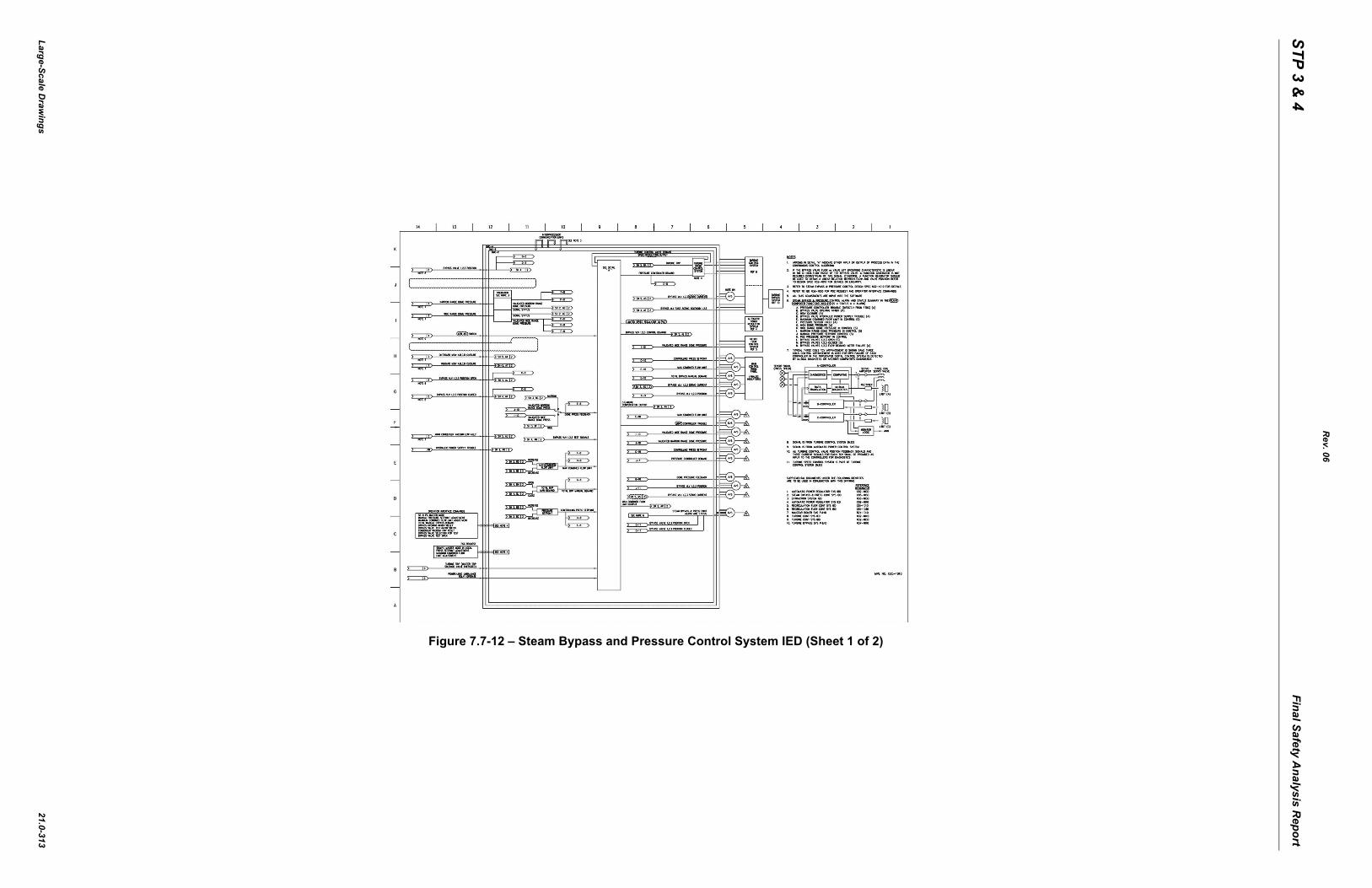
Figure 7.7-12 – Steam Bypass and Pressure Control System IED (Sheet 1 o
STP 3 & 4
Final Safety Analysis R
eport
Large-Scale Draw
ings
f 2)
Rev. 06
21.0-314
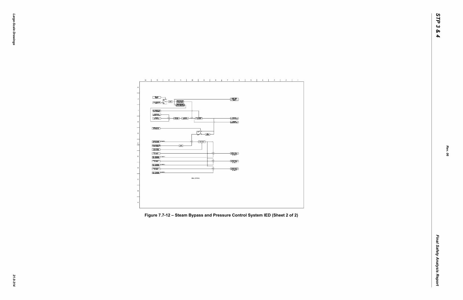
Figure 7.7-12 – Steam Bypass and Pressure Control System IED (Sheet 2 o
STP 3 & 4
Final Safety Analysis R
eport
Large-Scale Draw
ings
f 5)
Rev. 06
21.0-315
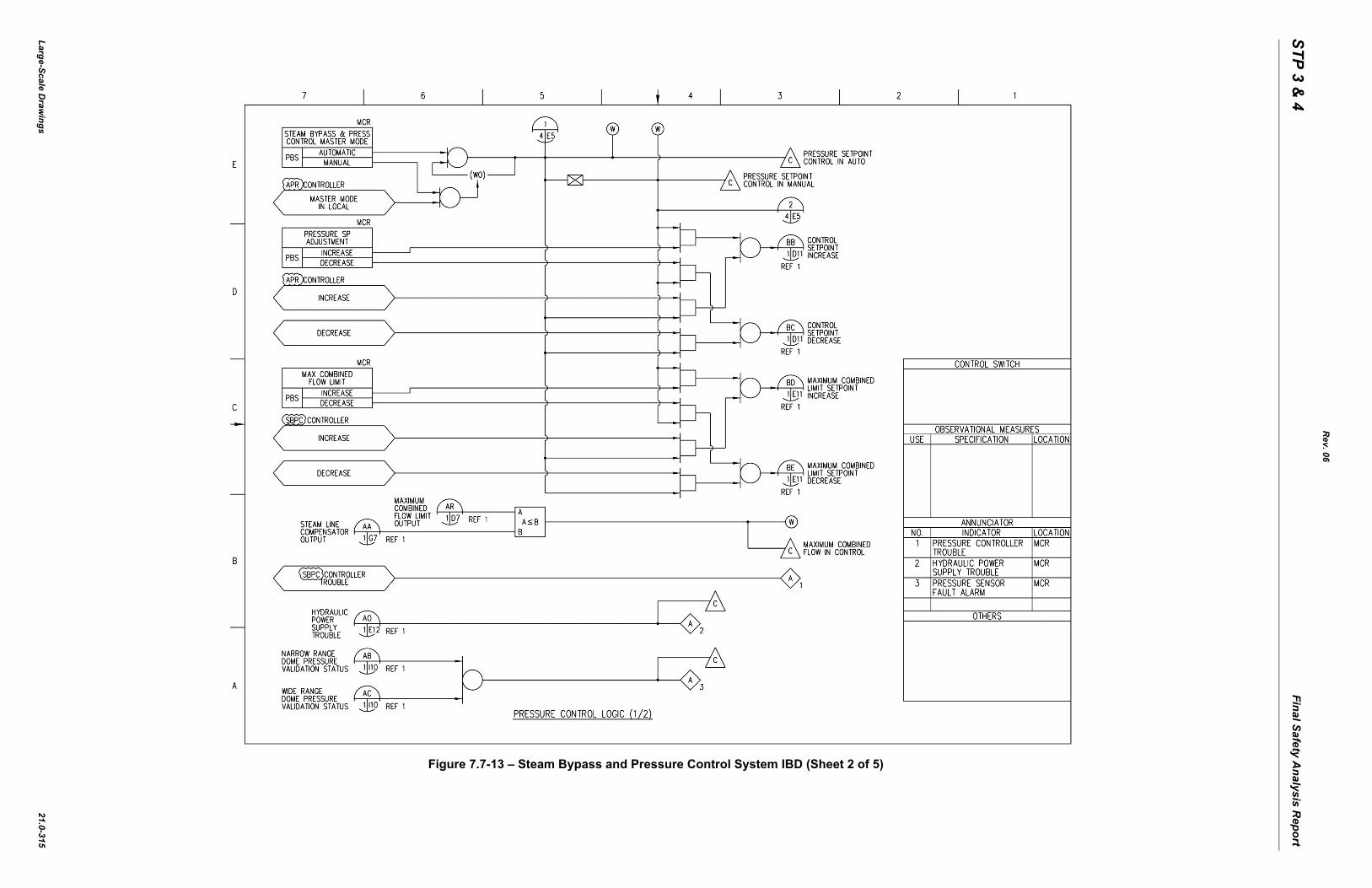
Figure 7.7-13 – Steam Bypass and Pressure Control System IBD (Sheet 2 o
STP 3 & 4
Final Safety Analysis R
eport
Large-Scale Draw
ings
f 5)
Rev. 06
21.0-316
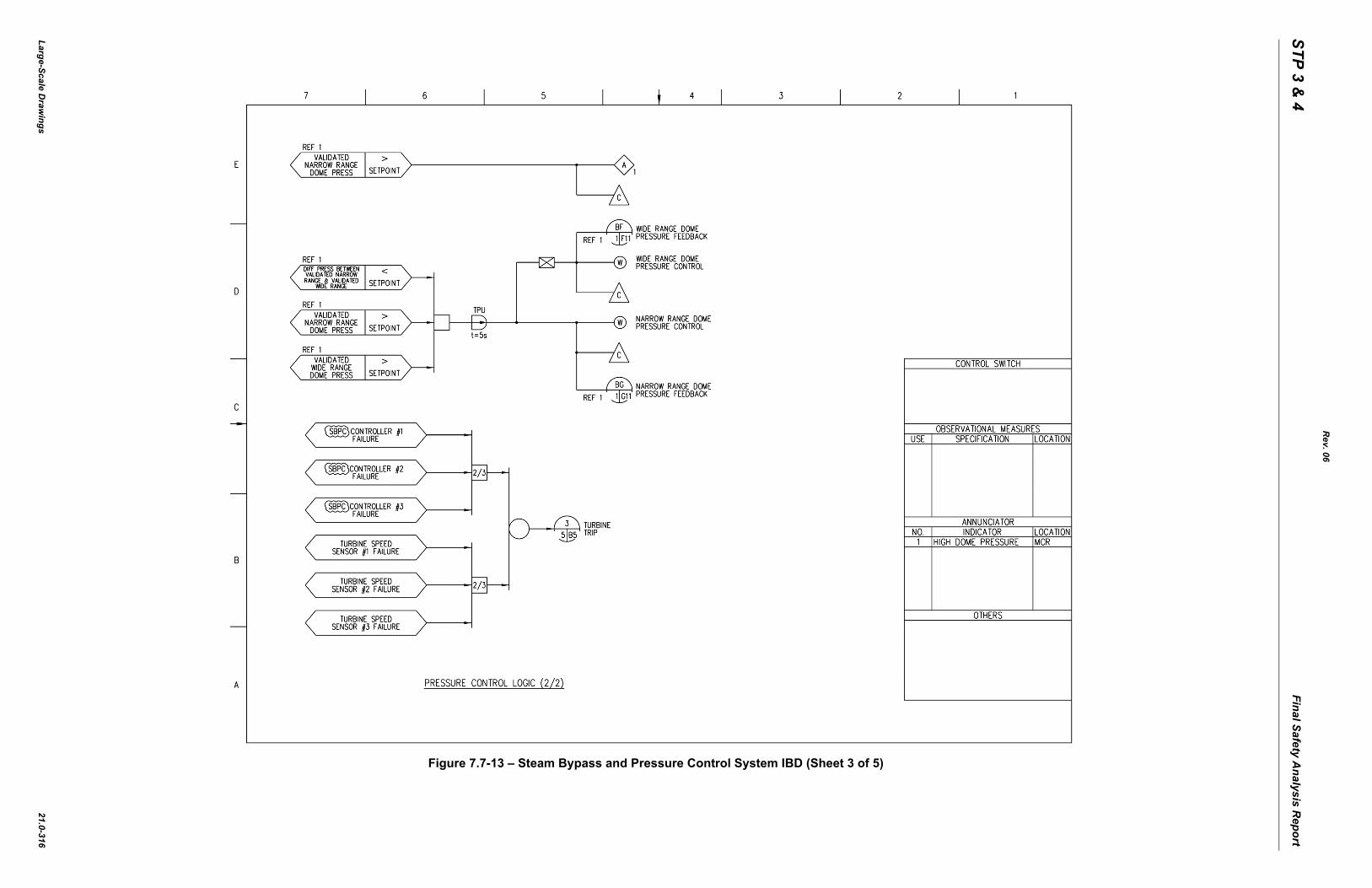
Figure 7.7-13 – Steam Bypass and Pressure Control System IBD (Sheet 3 o
STP 3 & 4
Final Safety Analysis R
eport
Large-Scale Draw
ings
f 5)
Rev. 06
21.0-317
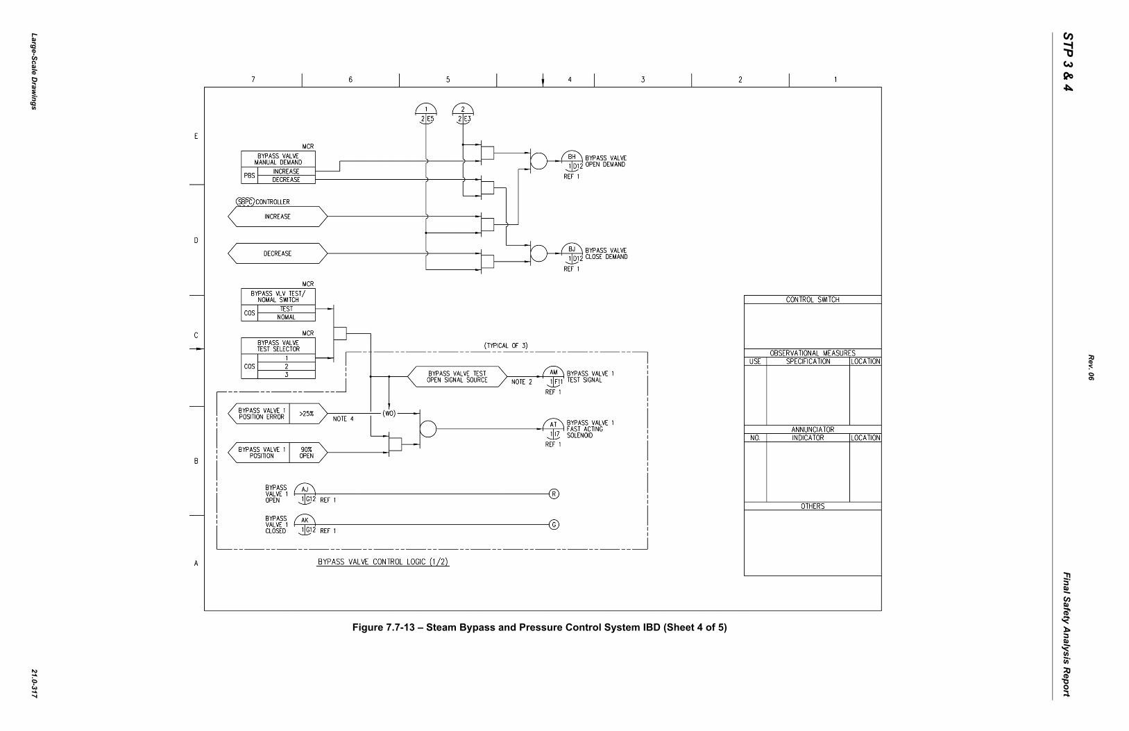
Figure 7.7-13 – Steam Bypass and Pressure Control System IBD (Sheet 4 o
STP 3 & 4
Final Safety Analysis R
eport
Large-Scale Draw
ings
f 5)
Rev. 06
21.0-318
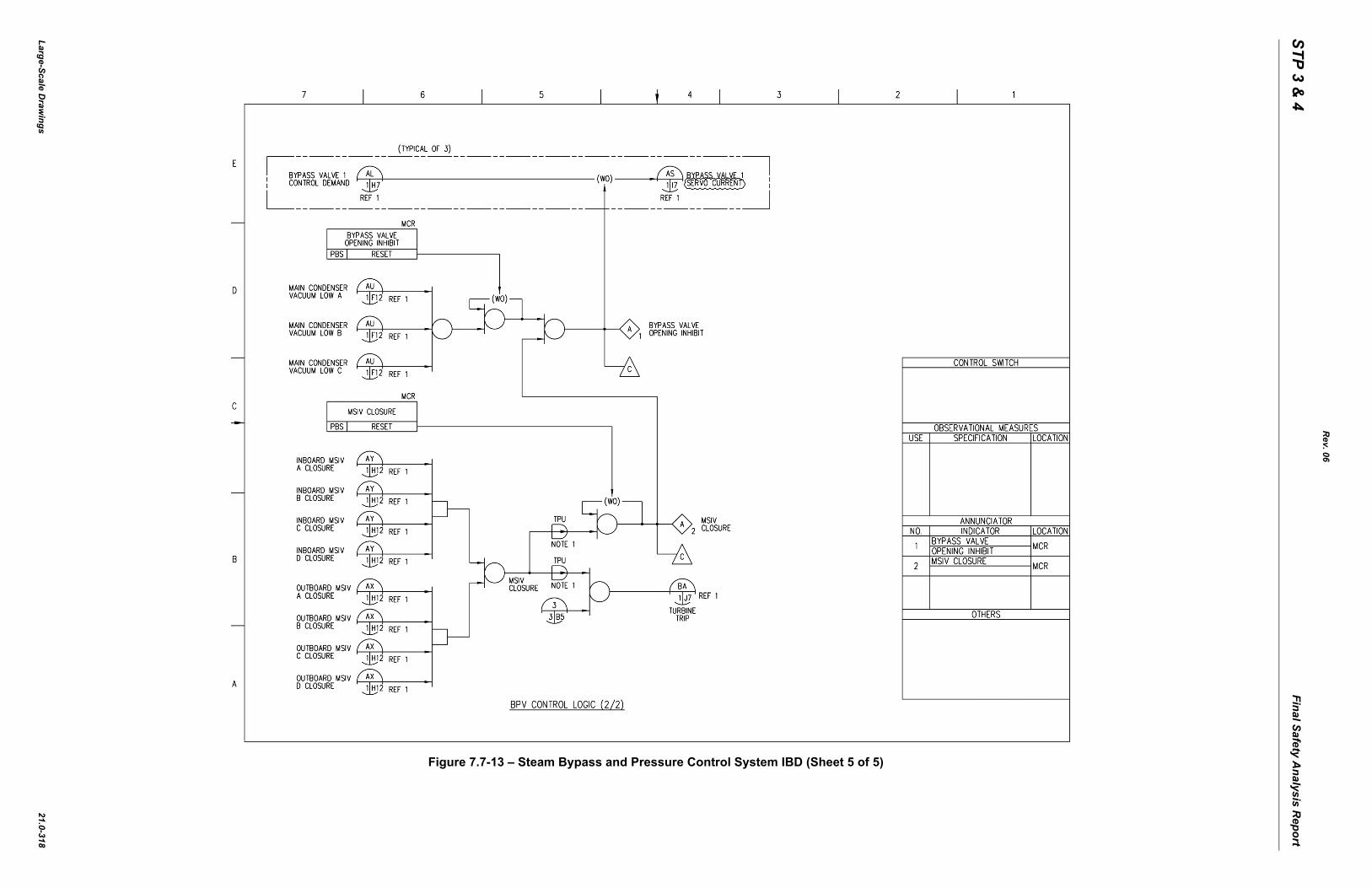
Figure 7.7-13 – Steam Bypass and Pressure Control System IBD (Sheet 5 o
STP 3 & 4
Final Safety Analysis R
eport
Proprietary Inform
ation
Large-Scale Draw
ings
Rev. 06
21.0-319
PROPRIETARY INFORMATION
Figure 8.2-1 – Power Distribution Routing Diagram (Sheet 1 of 7)

STP 3 & 4
Final Safety Analysis R
eport
Proprietary Inform
ation
Large-Scale Draw
ings
Rev. 06
21.0-320
PROPRIETARY INFORMATION
Figure 8.2-1 – Power Distribution Routing Diagram (Sheet 2 of 7)

STP 3 & 4
Final Safety Analysis R
eport
Proprietary Inform
ation
Large-Scale Draw
ings
Rev. 06
21.0-321
PROPRIETARY INFORMATION
Figure 8.2-1 – Power Distribution Routing Diagram (Sheet 3 of 7)

STP 3 & 4
Final Safety Analysis R
eport
Proprietary Inform
ation
Large-Scale Draw
ings
Rev. 06
21.0-322
PROPRIETARY INFORMATION
Figure 8.2-1 – Power Distribution Routing Diagram (Sheet 4 of 7)

STP 3 & 4
Final Safety Analysis R
eport
Proprietary Inform
ation
Large-Scale Draw
ings
Rev. 06
21.0-323
PROPRIETARY INFORMATION
Figure 8.2-1 – Power Distribution Routing Diagram (Sheet 5 of 7)

STP 3 & 4
Final Safety Analysis R
eport
Proprietary Inform
ation
Large-Scale Draw
ings
Rev. 06
21.0-324
PROPRIETARY INFORMATION
Figure 8.2-1 – Power Distribution Routing Diagram (Sheet 6 of 7)

STP 3 & 4
Final Safety Analysis R
eport
Proprietary Inform
ation
Large-Scale Draw
ings
Rev. 06
21.0-325
PROPRIETARY INFORMATION
Figure 8.2-1 – Power Distribution Routing Diagram (Sheet 7 of 7)
STP 3 & 4
Final Safety Analysis R
eport
Large-Scale Draw
ings
Rev. 06
21.0-326
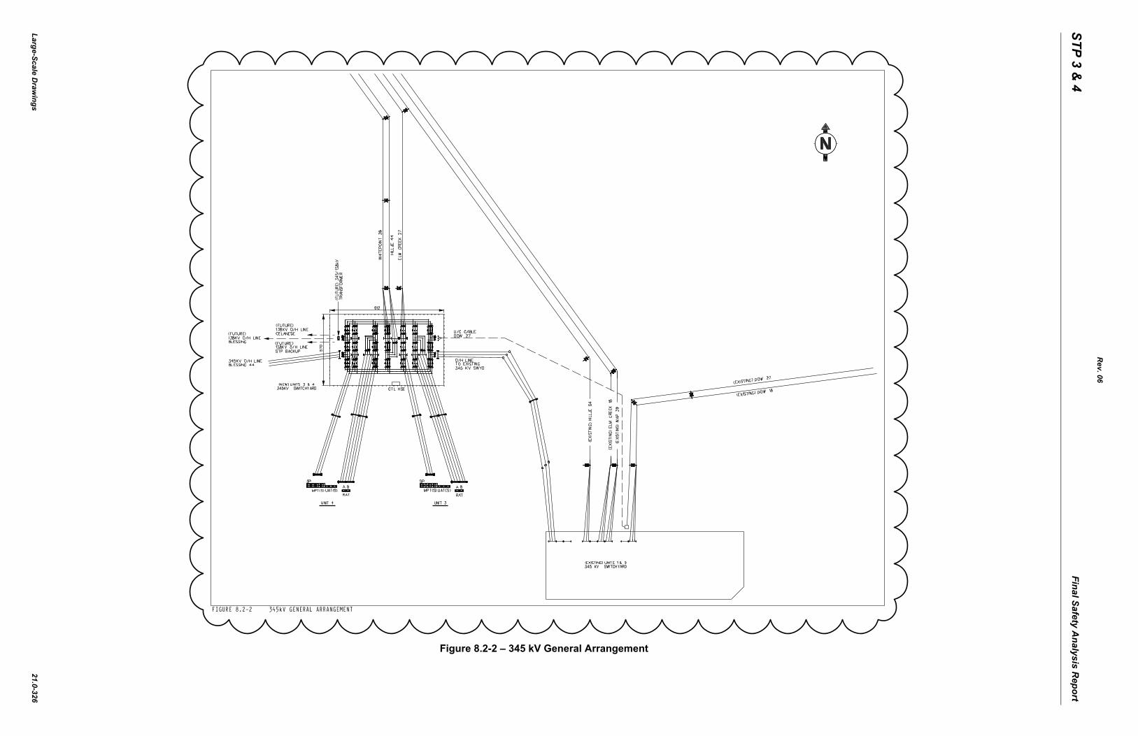
Figure 8.2-2 – 345 kV General Arrangement
STP 3 & 4
Final Safety Analysis R
eport
Large-Scale Draw
ings
Rev. 06
21.0-327
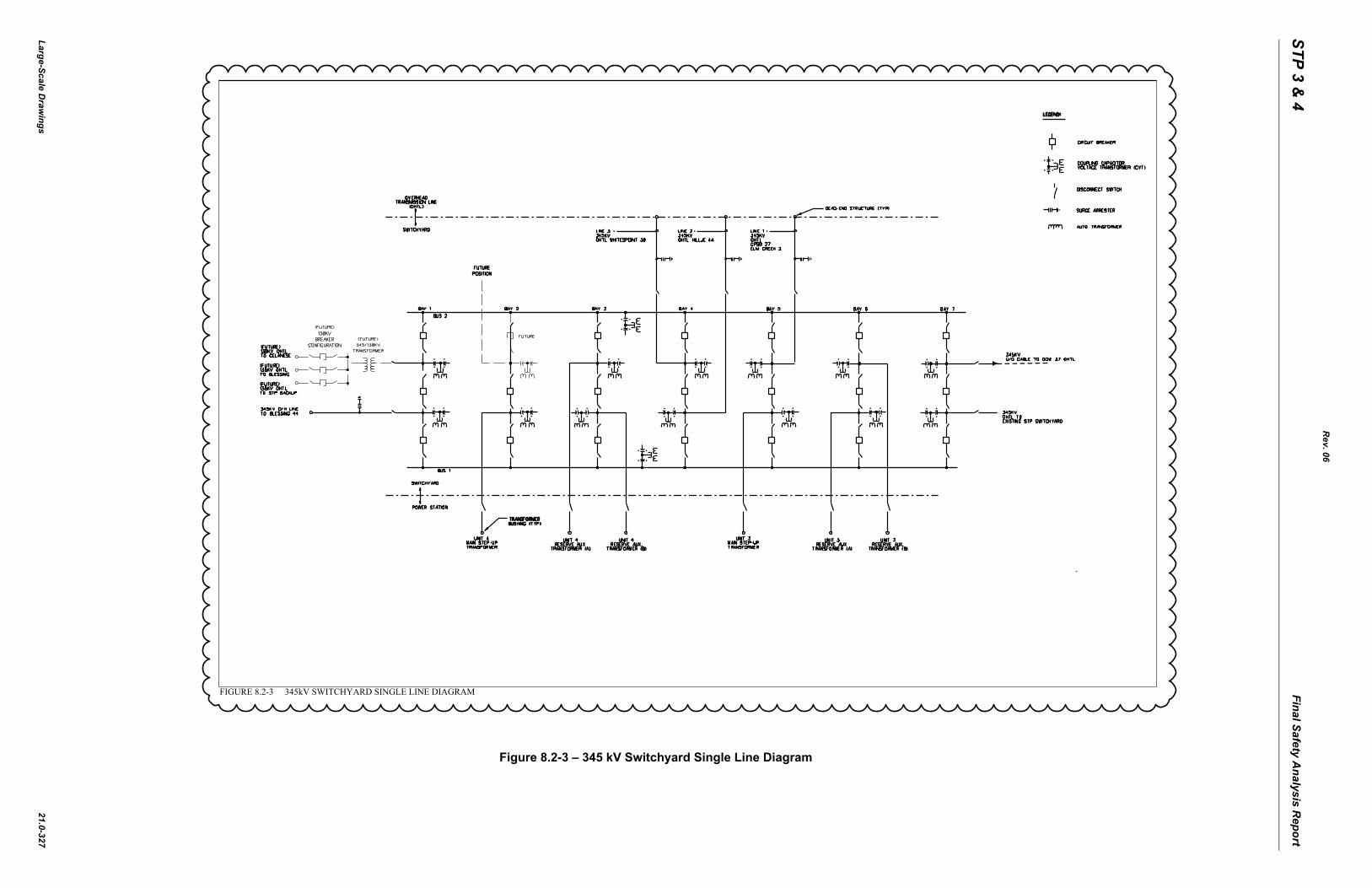
Figure 8.2-3 – 345 kV Switchyard Single Line Diagram
STP 3 & 4
Final Safety Analysis R
eport
Large-Scale Draw
ings
Rev. 06
21.0-328
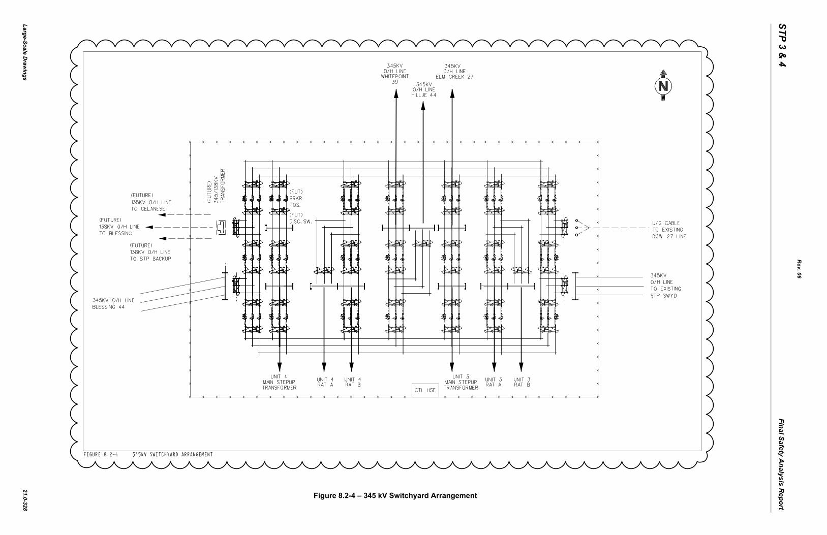
Figure 8.2-4 – 345 kV Switchyard Arrangement
STP 3 & 4
Final Safety Analysis R
eport
Large-Scale Draw
ings
Rev. 06
21.0-329
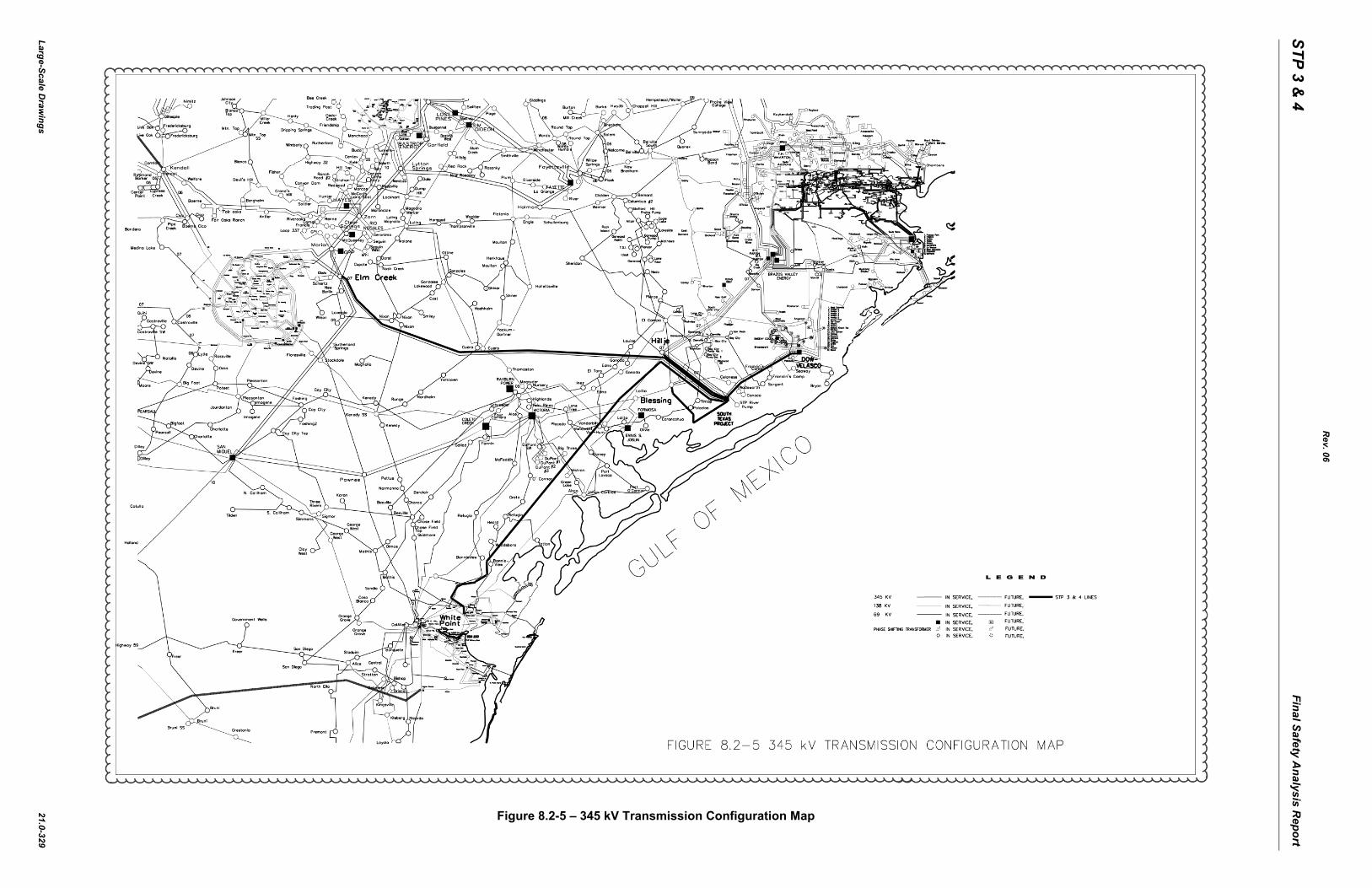
Figure 8.2-5 – 345 kV Transmission Configuration Map
STP 3 & 4
Final Safety Analysis R
eport
Large-Scale Draw
ings
Line)
Rev. 06
21.0-330
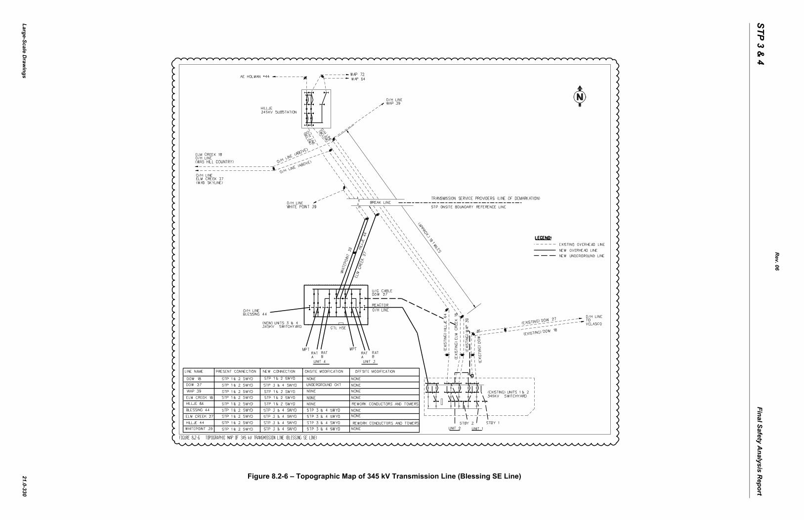
Figure 8.2-6 – Topographic Map of 345 kV Transmission Line (Blessing SE
STP 3 & 4
Final Safety Analysis R
eport
Large-Scale Draw
ings
t 1 of 4)
Rev. 06
21.0-331
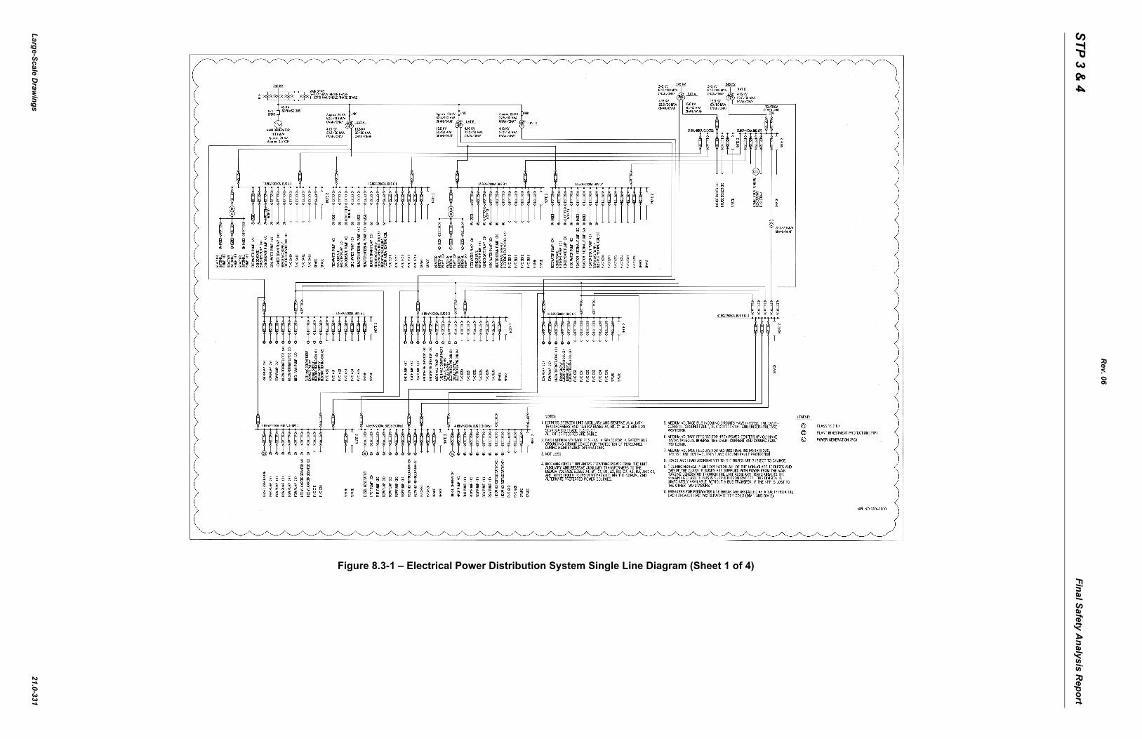
Figure 8.3-1 – Electrical Power Distribution System Single Line Diagram (Shee
STP 3 & 4
Final Safety Analysis R
eport
Large-Scale Draw
ings
t 2 of 4)
Rev. 06
21.0-332
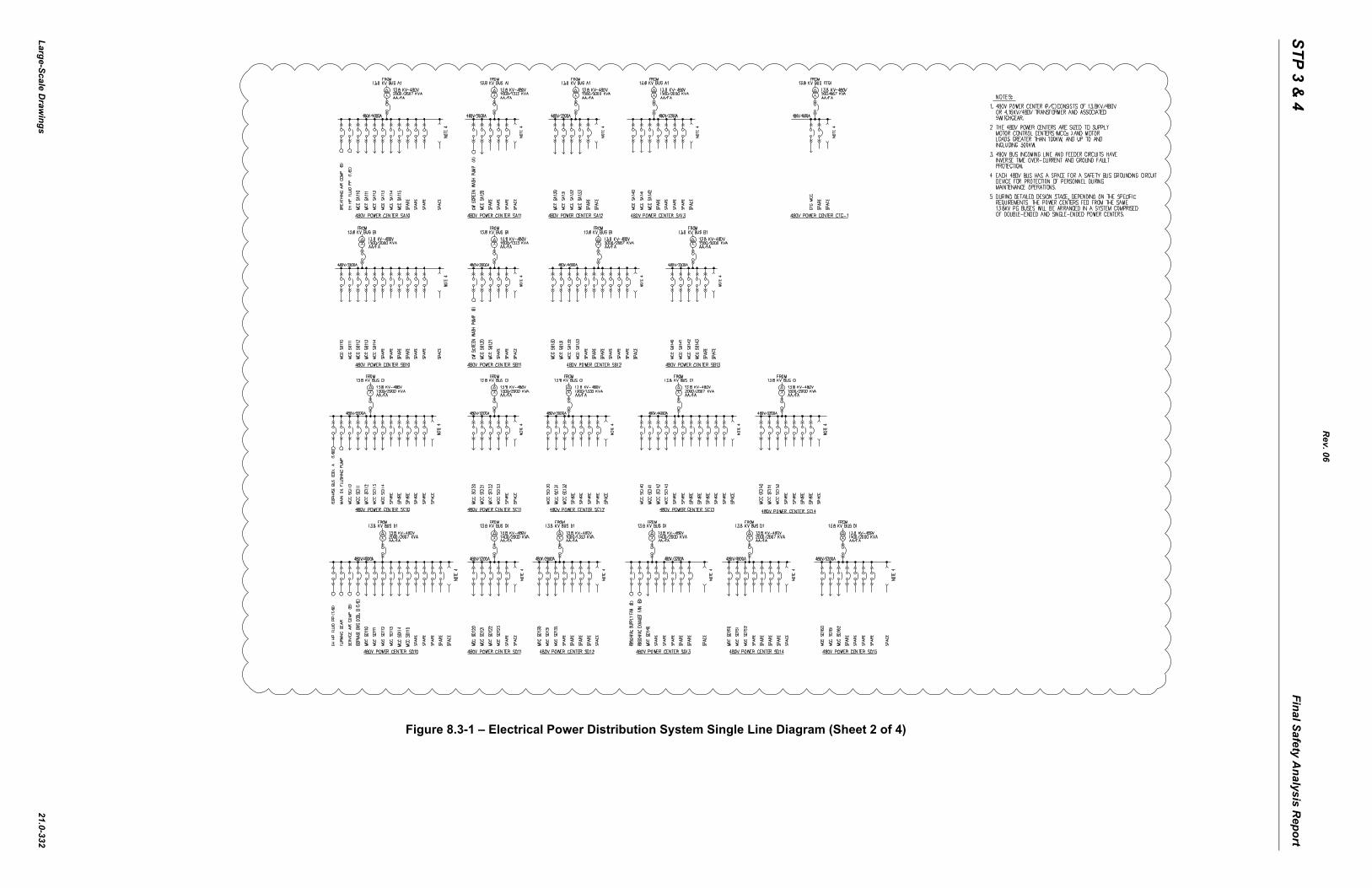
Figure 8.3-1 – Electrical Power Distribution System Single Line Diagram (Shee
STP 3 & 4
Final Safety Analysis R
eport
Large-Scale Draw
ings
t 3 of 4)
Rev. 06
21.0-333
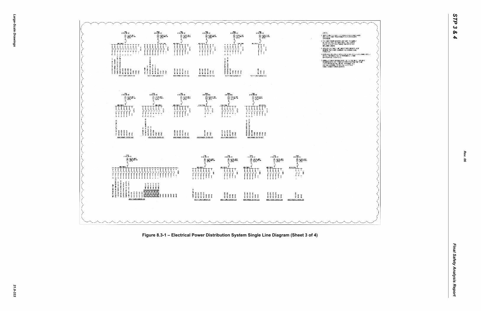
Figure 8.3-1 – Electrical Power Distribution System Single Line Diagram (Shee
STP 3 & 4
Final Safety Analysis R
eport
Large-Scale Draw
ings
t 4 of 4)
Rev. 06
21.0-334
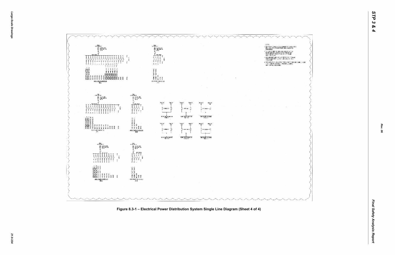
Figure 8.3-1 – Electrical Power Distribution System Single Line Diagram (Shee
STP 3 & 4
Final Safety Analysis R
eport
Large-Scale Draw
ings
Sheet 1 of 1)
ING�����
RMER
C/B MCC 480V F120
REGULATING
AC 120V DPIPD10
RBAC 120V DP
IPD20
CB
(DIV IV)
480/��������
TRANSFORMER
(DIV II)
Rev. 06
21.0-335
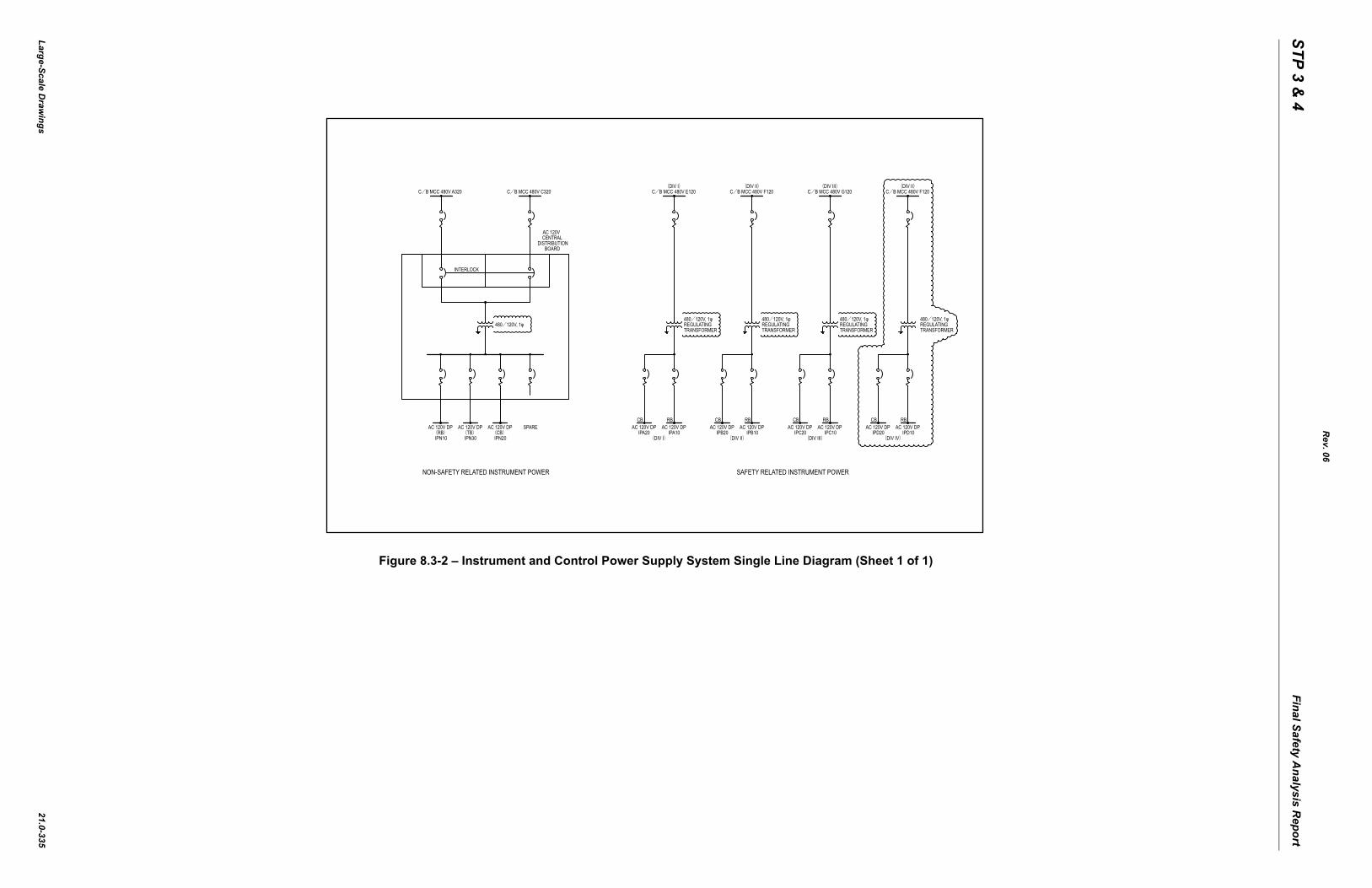
Figure 8.3-2 – Instrument and Control Power Supply System Single Line Diagram (
C/B MCC 480V A320 C/B MCC 480V C320
DISTRIBUTIONBOARD
CENTRALAC 120V
INTERLOCK
480/��������
AC 120V DP(RB)IPN10
AC 120V DP(TB)IPN30
AC 120V DP(CB)IPN20
SPARE
NON-SAFETY RELATED INSTRUMENT POWER
C/B MCC 480V E120
REGULATING
AC 120V DPIPA10
RBAC 120V DP
IPA20
CB
(DIV I)
480/��������
TRANSFORMER
(DIV I)C/B MCC 480V F120
REGULATING
AC 120V DPIPB10
RBAC 120V DP
IPB20
CB
(DIV II)
480/��������
TRANSFORMER
(DIV II)C/B MCC 480V G120
REGULAT
AC 120V DPIPC10
RBAC 120V DP
IPC20
CB
(DIV III)
480/���
TRANSFO
(DIV III)
SAFETY RELATED INSTRUMENT POWER