Embed Size (px)
Citation preview
1
Final Year Internship
Brockman Syncline 4 –Primary Crushing Facility
“A report submitted to the School of Engineering and Energy, Murdoch University in partial fulfilment of the requirements for the degree of Bachelor of Engineering”
Prepared By:Elliott Combes 30081194
2008

i
Abstract
This report presents the research and work completed by the author during completion
of a 16 week Internship as part requirement of the completion of a Bachelor of
Engineering with Murdoch University. Incorporating the project work surrounding the
design and implementation phase of a green-field project for a client in the iron ore
industry. The name of the project/plant being constructed is Brockman Syncline No.4
and the tasks associated with the project undertaken relates to Instrumentation and
Control. This report provides background to the project and an overview of the area of
focus whist providing more in-depth research in the particular area to provide the reader
with a sound background and knowledge into the operation of the equipment in the
plant. Other aspects of the project and associated tasks are also presented including the
allocation of the IO in the distributed IO system implementation and also the testing
practices for testing of PLC code written by other engineers in the team. Whilst the
tasks undertaken throughout the internship are broad they are linked by the work being
completed simultaneously by the other members of the team.
ii
Acknowledgements
Academic Supervisor – Dr Gareth Lee
Internship Unit Coordinator – Prof. Parisa Bahri
Supervisor/Engineer – Tim Galvin
Project Manager - Valerio Martinelli
Systems Engineer – Cobus Strydom
Systems Engineer – Peter Munns
iii
ContentsAbstract ........................................................................................................................ iAcknowledgements....................................................................................................... iiContents ...................................................................................................................... iiiTable of Figures........................................................................................................... iv1 Introduction.................................................................................................... 1
1.1 Engineering Internship ........................................................................... 1
1.2 Brockman 4 Project Overview............................................................... 2
2 Primary Crushing Circuit................................................................................ 42.1 Functional Specification Development ................................................... 4
2.2 Overview ............................................................................................... 5
2.3 Primary Crushing Operation................................................................... 7
2.4 Loading/ROM Bin ................................................................................. 9
2.5 Apron Feeder/Dribble Conveyor .......................................................... 10
2.6 Jaw Crusher ......................................................................................... 12
2.7 Primary Conveyor ................................................................................ 15
2.8 Vibrating Grizzly ................................................................................. 19
3 Distributed IO .............................................................................................. 253.1 Implementation of Remote I/O............................................................. 26
4 Abnormal Situation Management ................................................................. 274.1 Sources of Abnormal Events ................................................................ 28
5 Plant Control System.................................................................................... 305.1 Design Background.............................................................................. 30
5.2 Network ............................................................................................... 30
5.3 Control System Hardware .................................................................... 32
5.4 Modes of Operation.............................................................................. 36
6 Test Development ........................................................................................ 386.1 Introduction.......................................................................................... 38
6.2 Philosophy ........................................................................................... 39
7 Conclusion ................................................................................................... 408 References.................................................................................................... 419 Glossary ....................................................................................................... 42Appendix 2 - Event Count Unity DFV Test Record.................................................... 43
iv
Table of Figures
Figure 1-1 Process Overview Block Diagram................................................................ 3
Figure 2-1 Primary Crushing Circuit ............................................................................. 6
Figure 2-2 ROM Bin..................................................................................................... 9
Figure 2-3 Apron Feeder ............................................................................................. 10
Figure 2-4 VFD System ............................................................................................. 11
Figure 2-5 Jaw Crusher ............................................................................................... 12
Figure 2-6 Grizzly Feeder ........................................................................................... 19
Figure 2-7 Effect of Angled Vibration on Solid........................................................... 20
Figure 4-1 Sources of Abnormal Events ..................................................................... 28
Figure 5-1 Control System Communication Layout .................................................... 34
1
1 Introduction1.1 Engineering Internship
The Engineering Internship is an initiative implemented by Murdoch University to enable
final year students to complete an internship with an industry partner in order to satisfy the
requirements for Semester 2 of their final year. The Internship program gives students the
opportunity to apply and relate the skills learnt whilst studying their chosen degree. This
report provides an insight and background into the Internship completed by Elliott Combes
whilst working for Calibre Controls under the supervision of Tim Galvin. Dr Gareth Lee
provided academic support and supervision throughout the Internship programme. The
placement was a full time position for 16 weeks and this report incorporates background
information relevant to the tasks undertaken and also a description of the work completed
whilst completing the Internship.
During the Internship a Rio Tinto green-field project called Brockman Syncline No.4 was
the basis of the associated tasks. Being assigned to the controls team , the work, in the
early stages of the project, consisted predominantly of design and testing of documents and
PLC code to be used during the implementation stage.
2
1.2 Brockman 4 Project OverviewThe Brockman Syncline No. 4 Project is a proposed green field iron ore mine at the Mt
Brockman site in the Pilbara region of Western Australia. The Brockman Syncline No. 4
deposit is located in the central Pilbara region of Western Australia, approximately 60km
NW of Tom Price and 300 km SE of Dampier occupying 3 mineral tenancies.
The infrastructure and mine are contained within the Shire of Ashburton. At the
completion of construction the rail will run a course from Brockman Syncline No.4 to
Brockman 2. There after, ore from Brockman 4 will be transported along the Brockman 2
spur line to Rosella Siding and subsequently to Port Dampier for unloading and export via
ship.
The mine will be operated with a production output of 6Mtpa in the first year, rising
through 18Mtpa to 22Mtpa in the third year, and a planned 36Mtpa in the sixth year.
The Brockman Syncline No. 4 control systems and instrumentation have been proposed to
implement the Mining in the New Dimension (MiND) philosophy where practicable or if
not practicable to ensure that the technologies implemented do not preclude the future
implementation of this philosophy. “Mining in the New Dimension is a philosophy that
promotes active integration of production management of the complete supply chain from
a strategic level.” [1] Mine, plant, rail and port operations are actively managed at a local
level. Operational areas then coordinate the production in a peer to peer manner. The
production process is managed end to end at a strategic level, allowing optimisation of the
whole system, rather than just optimising subsystems and potentially deoptimising the
whole system.
3
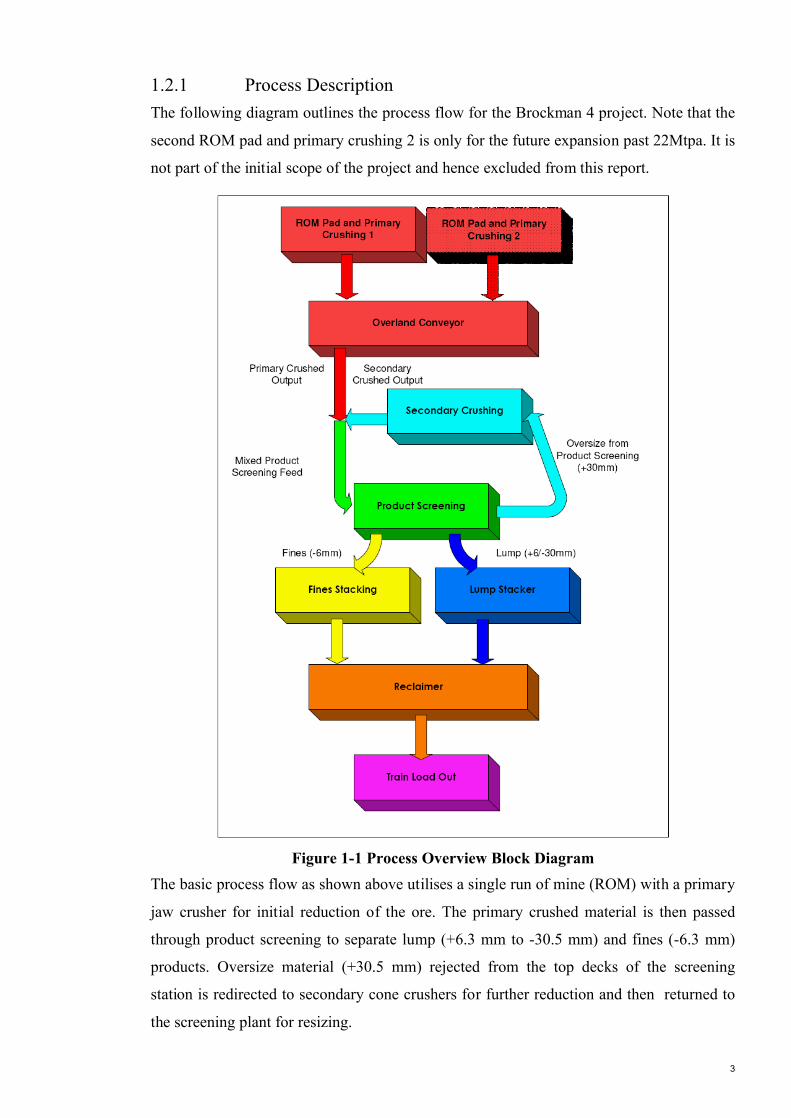
1.2.1 Process DescriptionThe following diagram outlines the process flow for the Brockman 4 project. Note that the
second ROM pad and primary crushing 2 is only for the future expansion past 22Mtpa. It is
not part of the initial scope of the project and hence excluded from this report.
Figure 1-1 Process Overview Block DiagramThe basic process flow as shown above utilises a single run of mine (ROM) with a primary
jaw crusher for initial reduction of the ore. The primary crushed material is then passed
through product screening to separate lump (+6.3 mm to -30.5 mm) and fines (-6.3 mm)
products. Oversize material (+30.5 mm) rejected from the top decks of the screening
station is redirected to secondary cone crushers for further reduction and then returned to
the screening plant for resizing.
4
2 Primary Crushing Circuit2.1 Functional Specification DevelopmentThe purpose for creating the functional specification is to describe the control system
functionality at a detailed level for the Brockman 4 Primary Crushing Plant. The content
of the document includes:
• A detailed description of how the system will operate;
• Sequence description – including system recovery, startup and shutdown;
• Equipment trips and alarm / warning descriptions;
• Control system general parameters;
• Links to reference documents.
The intended audience includes operators, process engineers and control system engineers
to aid in their understanding of how the equipment operates together as a system, and as
such, it serves as a client approval mechanism on how the system will work. This
document is not intended to be a manual on the system. However it may be used by the
training and technical authors to create a training manual for the primary crushing circuit.
It also serves as the primary document for identifying testable requirements. In order to
generate this document a thorough understanding of the primary crushing circuit is
required. This includes an understanding of the overall operation of the circuit as well as
specific equipment related knowledge in order to account for unique equipment behaviour
in the logic conditions. It is also necessary to understand the instrumentation associated
with the equipment as, it is with this equipment that the control system reads and writes the
input and outputs to the plant/equipment. This section of the report reflects the knowledge
developed of the primary crushing plant and also provides a more in depth description of
the equipment with in primary crushing from the control of it to the instrumentation
associated with the respective equipment. The flow of information represents the learning
approach adopted upon commencement of the task. It was first important to understand
how the equipment operated both on its own and as equipment in a group or area of the
plant, then understand the control that was necessary to achieve the desired operation.
Knowing what needed to be achieved meant that it was then necessary to work out how to
achieve the operation required; this happened via the instrumentation for the associated
equipment. It was not possible to include the Primary Crushing Functional Specification
however the control sections for each equipment represents the basis of the functional
specification a completed as a deliverable for the project and Internship.
5
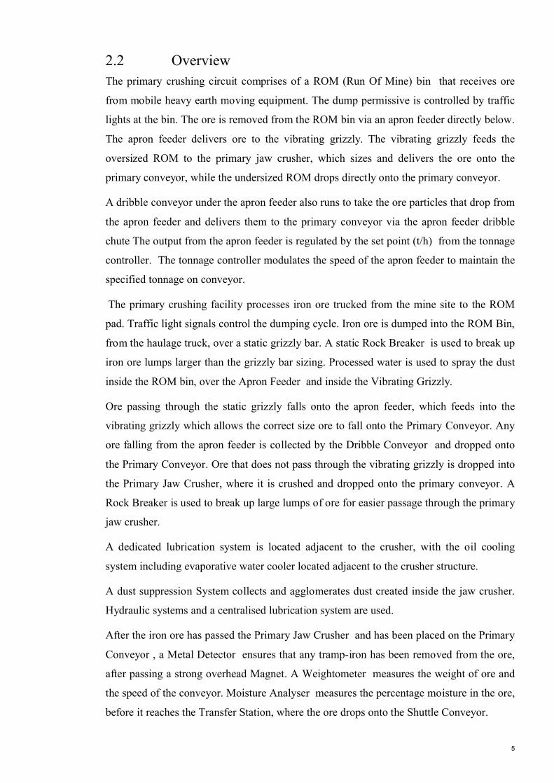
2.2 OverviewThe primary crushing circuit comprises of a ROM (Run Of Mine) bin that receives ore
from mobile heavy earth moving equipment. The dump permissive is controlled by traffic
lights at the bin. The ore is removed from the ROM bin via an apron feeder directly below.
The apron feeder delivers ore to the vibrating grizzly. The vibrating grizzly feeds the
oversized ROM to the primary jaw crusher, which sizes and delivers the ore onto the
primary conveyor, while the undersized ROM drops directly onto the primary conveyor.
A dribble conveyor under the apron feeder also runs to take the ore particles that drop from
the apron feeder and delivers them to the primary conveyor via the apron feeder dribble
chute The output from the apron feeder is regulated by the set point (t/h) from the tonnage
controller. The tonnage controller modulates the speed of the apron feeder to maintain the
specified tonnage on conveyor.
The primary crushing facility processes iron ore trucked from the mine site to the ROM
pad. Traffic light signals control the dumping cycle. Iron ore is dumped into the ROM Bin,
from the haulage truck, over a static grizzly bar. A static Rock Breaker is used to break up
iron ore lumps larger than the grizzly bar sizing. Processed water is used to spray the dust
inside the ROM bin, over the Apron Feeder and inside the Vibrating Grizzly.
Ore passing through the static grizzly falls onto the apron feeder, which feeds into the
vibrating grizzly which allows the correct size ore to fall onto the Primary Conveyor. Any
ore falling from the apron feeder is collected by the Dribble Conveyor and dropped onto
the Primary Conveyor. Ore that does not pass through the vibrating grizzly is dropped into
the Primary Jaw Crusher, where it is crushed and dropped onto the primary conveyor. A
Rock Breaker is used to break up large lumps of ore for easier passage through the primary
jaw crusher.
A dedicated lubrication system is located adjacent to the crusher, with the oil cooling
system including evaporative water cooler located adjacent to the crusher structure.
A dust suppression System collects and agglomerates dust created inside the jaw crusher.
Hydraulic systems and a centralised lubrication system are used.
After the iron ore has passed the Primary Jaw Crusher and has been placed on the Primary
Conveyor , a Metal Detector ensures that any tramp-iron has been removed from the ore,
after passing a strong overhead Magnet. A Weightometer measures the weight of ore and
the speed of the conveyor. Moisture Analyser measures the percentage moisture in the ore,
before it reaches the Transfer Station, where the ore drops onto the Shuttle Conveyor.

6
[Copyrighted Image Removed]
Figure 2-1 Primary Crushing Circuit [11]
7
2.3 Primary Crushing Operation This section discusses the modes of operation and the start and stop sequences during
operation.
2.3.1 Modes of Operation From the control room, the Process Control Room (PCR) operator can select the
primary crusher for any one of the following modes of operation:
• Automatic;
• Maintenance; or,
• Off.
In Maintenance mode, the primary crusher can be run by pressing its local start push-
button on the crusher local control panel. The crusher local control panel also has a stop
push-button that is active at all times. If the local stop push-button is pressed, the button
latches in its stopped (depressed) position and stops the crusher. The crusher will not
start in either the Automatic or Maintenance mode if the local stop push-button remains
in its depressed position.
In Maintenance mode, the primary crusher will not start if it is faulty. However, none of
the other interlock conditions will stop the crusher from starting in maintenance mode.
In the Off mode, the crusher will not run either locally or remotely.
2.3.2 Starting the Primary Crusher System The PCR operator can start the primary crusher in automatic mode with one sequence
start command for the primary crushing group. Provided all of the primary crushing
group drives are in automatic mode and all the necessary interlocks are satisfied, they
will start to operate according to the following sequence:
1. The tramp magnet energises and positions itself over the primary conveyor.
2. The primary conveyor starts to run provided the scalping surge bins are not full.
3. The primary crusher starts to run.
4. When the primary crusher runs satisfactorily for 30 seconds, the grizzly feeder
starts to run.
5. The apron feeder starts to run provided the ROM bin level is not too low.

8
2.3.3 Stopping the Primary Crusher System Similarly, the PCR operator can stop the primary crusher in automatic mode with one
sequence stop command for the primary crushing group, so that:
1. The apron feeder stops.
2. When the apron feeder stops, the grizzly feeder runs for 30 seconds to clear
itself of any ore and then stops.
3. When the grizzly feeder stops, the primary crusher runs for 30 seconds to empty
itself of ore and then stops.
4. When the primary crusher stops, the primary conveyor runs for 90 seconds to
clear itself or any ore and then stops.
5. The tramp magnet goes to its dump position and de-energises.
Any one of the following conditions partially or totally stops the primary crushing
group of equipment:
• Any item of equipment becomes faulty.
• The scalping surge bins becomes too full.
• The dump hopper level becomes too low.
• The automatic grease application system fails to complete a crusher lubrication
cycle in 8 hours.
All drives upstream of the problem area stop immediately while the drives that are
downstream of the problem area keep running. If the problem cannot be solved quickly
then the PCR operator can stop all running drives in the group.
9
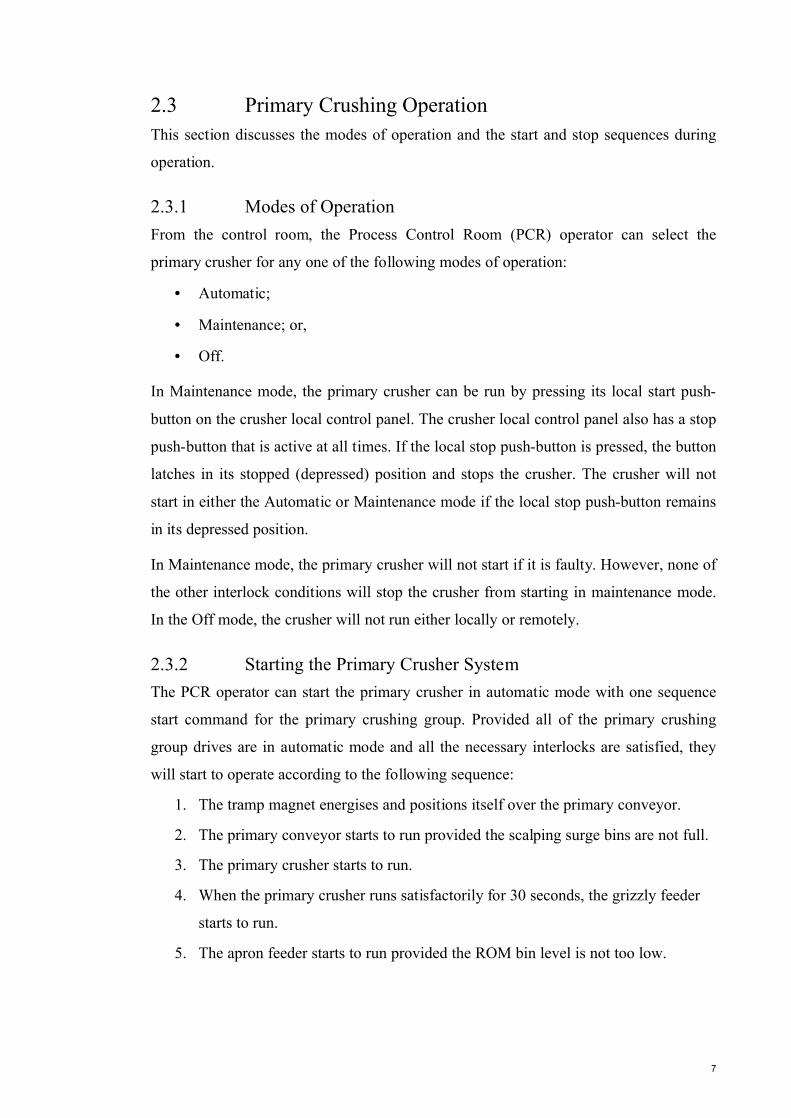
2.4 Loading/ROM BinThe ROM bin has a 600 t capacity of ore and operates in association with a set of
tipping traffic lights, and a set of water sprays (deluge, mist & fog) to settle dust. The
sprays are so-called according to the type of nozzle fitted and method of delivery.
Static grizzly bars are installed inside the ROM bin and are constructed from large ‘I’
beams with internal and external bracing. “Wear liners protect the bars which are
tapered slightly from top to bottom to reduce rock jams. Rubber blocks are placed in the
mounting brackets, reducing the impact shock of large rocks.”[6]
[Copyrighted Image Removed]
Figure 2-2 ROM Bin [6]The static grizzly bars are spaced approximately 1.25 m apart to capture the larger
rocks. If larger rocks are captured by the bars these are broken down using a Rock
Breaker. A Rock Breaker is a large hydraulic jack hammer that is remotely operated that
can reach inside the ROM bin to break up any oversized rocks.
2.4.1 Control
High-level Set Point
When in automatic mode, this controller turns the tipping traffic light red when the bin
level rises above its high level to stop further dumping of ore. It turns the traffic light
green when the level falls below its high set point. This set point is set such that when
the bin level is below its high set point, the bin has the capacity to take another
truckload of ore
Low-level Set Point
The ROM bin also has a low-level set point. Should the bin level fall below this set
point, the control system stops the apron feeder, preventing the level falling any further.
Below this minimum level, the apron feeder will not have enough ore on top to protect
it against damage caused by the impact of large rocks.

10
There are times when the ROM bin needs to be emptied for maintenance purposes. On
such occasions, the operator can disable the operation of the bin low level and run the
apron feeder until the bin is empty.
2.4.2 InstrumentationA radar level transmitter continuously measures the ROM bin level and transmits
current bin levels to a traffic light controller. The operator has full control of the traffic
lights and can disable the automatic operation of the tipping traffic light and force it to
turn red or green, regardless of the bin level.
2.5 Apron Feeder/Dribble ConveyorThe apron feeder has to hydraulic motors on each side of its drive shaft at its discharge
end. The motors have a hydraulic power pack that provides it with motive power. The
motors run in the forward direction for normal operation of the apron feeder. The
motors can be locally run in reverse for maintenance purposes. The apron feeder motor
is wired to an electrical speed controlled Variable Voltage Variable Frequency (VVVF)
motor that allows the speed rate to be varied during operation.
[Copyrighted Image Removed]
Figure 2-3 Apron Feeder [4]
11
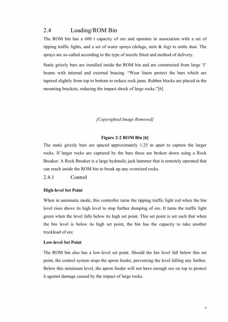
VVVF Motors – Background Theory
VVVF is used to control the rotational speed of an alternating current motor, by
controlling the frequency of the electrical power supplied to that motor [2]. When a
VVVF motor starts, it initially applies low frequency and voltage to the motor. The
starting frequency is typically 2 Hz or less. Starting at such a low frequency avoids the
high inrush current that occurs when a motor is started by simply applying the utility
(mains) voltage by turning on a switch. When a VVVF motor starts, the applied
frequency and voltage are increased at a controlled rate or ramped up to accelerate the
load without drawing excessive current. This starting method typically allows a motor
to develop 150% of its rated torque while drawing only 50% of its rated current. When a
motor is simply switched on at full voltage, it initially draws at least 300% of its rated
current while producing less than 50% of its rated torque [2]. As the load accelerates,
the available torque usually drops a little and then rises to a peak while the current
remains very high until the motor approaches full speed.
[Copyrighted Image Removed]
Figure 2-4 VFD System [2]A VVVF motor can be adjusted to produce a steady 150% starting torque from standstill
right up to full speed while drawing only 50% current.
With a VVVF motor, the stopping sequence is just the opposite as the starting sequence.
The frequency and voltage applied to the motor are ramped down at a controlled rate.
When the frequency approaches zero, the motor is shut off. A small amount of braking
torque is available to help decelerate the load a little faster than it would stop if the
motor were simply switched off and allowed to coast. Additional braking torque can be
obtained by adding a braking circuit to dissipate the braking energy or return it to the
power source.
12
2.6 Jaw CrusherThe primary crusher receives the oversized ROM from the grizzly feeder and crushes it
to below 150 mm in size before discharging the crushed ROM onto the primary crusher
product conveyor.
“The primary crusher of Brockman 4 Mine is a Nordberg C160 single-toggle jaw
crusher. It has a feed opening of 1600 by 1200mm and has a maximum capacity of
880t/h. Its closed-side-setting (CSS) is adjustable between 285 and 150 mm. A 250 kW
electric motor drives the crusher.” [3]
The distinctive feature of the jaw crusher is the two plates that open and shut like animal
jaws. The two plates are normally at an acute angle to each other, and one jaw has a
pivot so that it can swing relative to the fixed jaw. The jaw crusher is shown below in
Figure 2-5. Movements of the jaw alternatively nip and release rocks of ore that are
between the jaws. This crushes the rocks into smaller fragments and allows them to
move down the crushing chamber. Eventually, crushed rocks falls from the crushing
chamber into a discharge chute and onto the primary conveyor.
[Copyrighted Image Removed]
Figure 2-5 Jaw Crusher [3]To convert the rotary movement of a motor into the required movement of the swing
jaw, crusher designs use an eccentric shaft and either one or two toggle plates. Crushers
that use one toggle plate are called single-toggle jaw crushers. Similarly, crushers that
use two toggle plates are called double-toggle jaw crushers. In the Brockman 4 mine a
single-toggle design is used. As mentioned the swing jaw hangs from an eccentric shaft.
13
As the crusher motor turns the eccentric shaft, the upper part of the swing jaw orbits
around the centre rotation. A single toggle plate that holds the swing jaw near its bottom
end converts the swing jaw movement into an elliptical jaw motion which results in the
rocks being moved through the crusher as they are crushed.
2.6.1 ControlThe primary crusher normally operates in automatic mode as part of the primary
crushing group. In this mode, its operation is linked with the operation of other items of
equipment in the group.
The process control room operator can start the primary crusher in automatic mode with
one sequence start command for the primary crushing group. Provided all of the primary
crushing group drives are in automatic mode and all of the necessary interlocks are
satisfied, they will start to operate.
Certain conditions partially or totally stop the primary crushing group of equipment:
• Any one of the items becoming faulty;
• The scalping surge bins becoming to full;
• The dump hopper level becoming too low; or
• The automatic grease application system failing to complete a crusher
lubrication cycle in eight hours.
The crusher can be stopped by the operator in automatic mode with one sequence stop
command for the primary crushing group which stops all drives in the circuit
sequentially.
Level Control
Clark [4] states that a jaw crusher works at its optimum when it is 'choke' fed, because
the weight of the rock pushing down into the crusher creates an even feed into the jaws
of the crusher. In this application the primary jaw crusher is maintained between 90%
and 70% of its maximum capacity by an ultrasonic level transmitter. When the bin level
is above the control operator placed set-point, e.g. 50% the red ‘no tip’ light will
activate conversely when the bin level drops bellow 50% the green ‘OK to tip’ light will
activate. When the bin level drops to a low set point 10% the apron feeder will stop to
ensure a layer of material is left on the apron feeder pans for protection.
14
2.6.2 InstrumentationAs mentioned previously the level in the jaw crusher is monitored using an ultrasonic
level transmitter. Because of the variable nature of the rock size, the echo processing
has to be very good to provide an accurate level and stop the crusher either 'starving' or
overflowing. The transmitter emits a sound pulse from the transducer towards the ROM
bin material, this sound pulse is reflected from the material and is received by the
transducer. Using the speed of sound the time between the pulse and echo is used to
calculate the distance to the material. This information is in turn used to calculate the
quantity of material in the ROM bin, shown on the HMI screen as a bin percentage.
Instrumentation on the jaw crusher is installed more so for conditioning monitoring
rather than monitoring of the process itself.
The jaw crusher also has 4 RTD’s installed to provide the operators and engineers with
feedback as to the temperature of the bearings. These temperature inputs are used to
monitor the condition of the bearings and to detect a high temperature which is
generally an indication of the bearing failing.
15
2.7 Primary ConveyorThe primary conveyor is used to transport the ore from primary to the secondary
crushing and screening transfer tower. A typical conveyor drive unit consists of the
following items of equipment:
• An electric motor that provides the driving power for the unit.
• A coupling that connects the motor to a reduction gearbox and compensates for
small misalignments that may exist between the motor and gearbox.
• A disc brake that is attached to the output shaft of the coupling and stops the unit
from rotating when the motor is switched off.
• A reduction gearbox that reduces the speed of the motor for driving the
conveyor belt at its correct speed.
The electric motor of each conveyor drive unit has the necessary power to drive its
conveyor at its full design load. Generally there are two types of electric motors:
• Those that have soft start capability; and
• Those that are direct online.
Electric motors that have soft start capability start at a low speed and then ramp up to
their full speed over a period of time that depends on the conveyor load. The period will
be short if the conveyor starts with no load; it will be relatively long if the conveyor
starts with full load. The reason for implementing the soft start is to prevent damage to
the drive and improve the reliability of the drive, subsequently reducing down time.
2.7.1 ControlThe primary conveyor takes crushed material from the primary jaw crusher and deposits
it into the head chute of the transfer tower. The primary conveyor also receives the fine
ore particles that fall through the apron feeder and ore particles that pass through the
grizzly deck.
The primary conveyor normally operates in automatic mode as part of the primary
crushing group. In this mode, its operation is linked with the operation of other items of
equipment in the group.
16
2.7.2 InstrumentationEach conveyor normally has the following monitoring and measuring instruments to
stop it when faults develop, and to provide the necessary information to the process
control system:
• pull-wire switches;
• belt-drift switches;
• belt-rip detectors;
• blocked-chute switches;
• under-speed switches;
• tachometers;
• moisture analysers; and
• belt weighers.
Pull-wire switches
Pull-wire switches are installed at nearly equal intervals on both sides of a conveyor and
then connected to trip wires that run along the sides of the conveyor. They are for
people to stop the conveyor in cases of emergencies. To activate them, a person can
simply pull the trip wire. Once activated, a pull-wire switch stops the conveyor
immediately if the conveyor is running in automatic or maintenance mode. It also
prevents the conveyor from starting in either mode. The switch must be manually reset
to allow the conveyor to start.
Belt-drift switches
Belt-drift switches continuously monitor the correct positioning of a conveyor belt. If a
belt-drift switch detects a drift in the belt when the conveyor is running in automatic
mode, it stops the conveyor immediately and prevents it from starting. However, these
switches do not affect the conveyor operation in maintenance mode.
After correcting the drift of the belt, the activated belt-drift switch can be reset by
running the conveyor in maintenance mode for a short time.
Belt-rip detectors
Belt-rip detectors continuously monitor a conveyor for any tear in the conveyor belt.
There are two possible types that can be installed as described below:
17
1. A pan-type detector that has a pan placed under the belt. If there is a tear in the
belt, some of the materials carried by the belt fall on the pan through the tear and
cause the pan to tilt. This activates a switch in the detector.
2. A wire-type detector that contains a wire, normally a fishing line, running across
and closely under the belt. If there is a tear in the belt, the torn piece will cut the
wire, causing a switch in the detector to activate.
If a belt-rip detector activates, it stops the conveyor immediately if the conveyor is
running in automatic or maintenance mode. It also prevents the conveyor from starting
in either mode. The detector must be manually reset to allow the conveyor to start.
This can be done by replacing the broken wire in the wire-type detector or removing the
material on top of the pan in the pan-type detector.
Blocked-chute switch
A blocked-chute switch is a mechanically activated switch that ensures the discharge
chute of a conveyor is clear when the conveyor is running in automatic mode. If the
discharge chute becomes blocked, build-up of materials activates the switch to
immediately stop the conveyor. However, this does not prevent the conveyor from
running in maintenance mode.
The blocked-chute switch will automatically reset itself to allow the conveyor to start in
automatic mode once the chute has been unblocked and the material build-up has been
cleared.
Under-speed Switch
Each conveyor has an under under-speed switch at its tail (non-driven end) pulley. The
switch continuously counts the number of times it receives signals from the two flags
installed at one end of the tail pulley within a specified time. Since the speed of each
conveyor belt is different, the number of counts that corresponds to the correct speed of
a belt differs from one conveyor to another. For example, 50 counts in one minute may
represent the correct speed for one conveyor while 76 counts in one minute may
represent the correct speed for another conveyor. So, each under-speed switch has a
different set point that represents the minimum acceptable number of counts in a
specified time for its conveyor. Counts below the set point is a sign that the conveyor
belt is slipping and, consequently, the switch stops the conveyor if the conveyor is
18
running in automatic mode. The switch requires no resetting and allows the conveyor to
restart immediately after stopping it.
Weightometer
The conveyor weightometer is located after the tramp-metal magnet and metal detector.
The tonne values generated from the weightometer regulate the feed rate from the
variable frequency feeder ( apron feeder), when the tonne rate exceeds the set point for a
conveyor the feeder will slow down to reduce feed onto the conveyor, when the feed
rate falls below the set point the feeder will gradually increase speed to meet the
tonnage value.
Similar to an under-speed unit the weightometer also uses a proximity sensor adjacent
to a pulley to indicate belt speed, conveyor weight is calculated from belt speed and
registered from the weighing unit.
Build up of material on the weightometer can cause false readings, which impact on
feed rates; these need to be cleaned off regularly.
The weightometer needs to be calibrated regularly using a known weight so that they
maintain their accuracy.
Moisture Analyser
It is likely for this plant that the moisture analysers used will be the same as previously
installed on other Rio Tinto plants.
The MA-500 moisture analyser is powered by microwave measurement technique, it
provides real-time information on product moisture content via a local HMI and through
integration with the SCADA control system. ‘The MA-500 outputs both analog and
digital data enabling immediate manual process adjustment and real-time process
automation’ [5]. The MA-500 is used in this application to control the moisture dosing
achieved by the water sprays through the primary crushing circuit. The analyser is
installed across the conveyor and does not interfere with the product flow.
‘The MA-500HDi is purpose-engineered for the iron ore industry to accommodate high
density ores and concentrates, large variations in bulk density and fluctuating bed depth.
‘[5].

19
2.8 Vibrating GrizzlyThe vibrating grizzly feeder takes the ROM from the apron feeder and separates it into
two streams:
• the undersized ROM that mainly contains particles below 500 mm in size; and
• the oversized ROM that mainly contains rocks 500 mm in size or larger.
The grizzly feeder feeds the oversized ROM to the primary jaw crusher while the
undersized ROM drops directly onto the primary crusher product conveyor. This
conveyor also takes the output of the primary crusher and delivers its load to the
scalping surge bins.
[Copyrighted Image Removed]
Figure 2-6 Grizzly Feeder [6]Figure 2-6 shows the main features of the grizzly feeder. The feeder consists mainly of
a screen box assembly that rests on nine upper and five lower isolator springs on each
side. The screen surface of the grizzly consists of an impact plate at the inlet side and
then four rows of bar grates. The open spaces between the bar grates allow particles of
ore that are below 500 mm in size to go through. Larger particles travel on top of the
bar grates and eventually fall from the discharge end of the screen surface. The impact
plate and the first row of bar grates have a downward slope of about 15 degrees to help
ore particles to move forward. The remaining three rows of bar grates slope down at an
angle of about 10 degrees. [6]
Whilst the concept of rocks vibrating on a grate and some falling through and others
being moved along seems fairly simple at first, there is in fact many factors and
mechanical movements that must be accounted for to achieve optimal throughput. When
a surface vibrates, it applies a force to each solid particle on the surface that throws the
particle in the direction of vibration. For example, if we have a number of stones
resting on a flat horizontal surface, a vertical vibration of the surface will cause the
20
stones to hop up and down. Similarly, if we have a number of stones resting on a flat
horizontal surface, a horizontal vibration of the surface will cause the stones to vibrate
with the surface. However, if we make the flat horizontal surface vibrate at a direction
which is between the vertical and horizontal directions, the rocks on the surface will
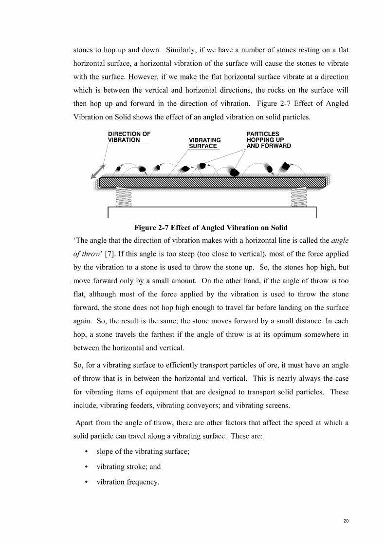
then hop up and forward in the direction of vibration. Figure 2-7 Effect of Angled
Vibration on Solid shows the effect of an angled vibration on solid particles.
Figure 2-7 Effect of Angled Vibration on Solid ‘The angle that the direction of vibration makes with a horizontal line is called the angle
of throw’ [7]. If this angle is too steep (too close to vertical), most of the force applied
by the vibration to a stone is used to throw the stone up. So, the stones hop high, but
move forward only by a small amount. On the other hand, if the angle of throw is too
flat, although most of the force applied by the vibration is used to throw the stone
forward, the stone does not hop high enough to travel far before landing on the surface
again. So, the result is the same; the stone moves forward by a small distance. In each
hop, a stone travels the farthest if the angle of throw is at its optimum somewhere in
between the horizontal and vertical.
So, for a vibrating surface to efficiently transport particles of ore, it must have an angle
of throw that is in between the horizontal and vertical. This is nearly always the case
for vibrating items of equipment that are designed to transport solid particles. These
include, vibrating feeders, vibrating conveyors; and vibrating screens.
Apart from the angle of throw, there are other factors that affect the speed at which a
solid particle can travel along a vibrating surface. These are:
• slope of the vibrating surface;
• vibrating stroke; and
• vibration frequency.

21
The slope of a vibrating surface, when aligned with the direction of vibration, will help
the solid particle travel faster. Conversely, the slope of a vibrating surface against the
direction of vibration will slow down the travel of the solid particles. The slope of the
vibrating surface in an item of equipment, similar to its angle of throw, is fixed and
cannot be changed.
The vibration frequency of a vibrating body is the number of times the body moves
from one extreme to the other and then back in one second. When a body moves from
one extreme to the other and then back, it completes one cycle of vibration (or
oscillation). Everything else remaining the same, ’if we increase the vibration
frequency of a vibrating item of equipment, we increase the flow rate of the material
handled by the equipment’ [6]. Conversely, if we decrease the vibration frequency, we
decrease the flow rate of the material.
There are two common ways of producing the required vibration in an item of
equipment:
• by an electromagnetic drive unit; or
• by rotating unbalanced weights with one or more electric motors.
Since the vibrating grizzly used in Brockman 4 uses the second method this section will
explain how we can produce the required vibration in vibrating items of equipment by
rotating unbalanced weights.
The key to the use of centrifugal forces, is that the centrifugal force results in a pull
away form the centre of rotation. Rotating objects may be balanced or unbalanced
depending on their application. Except in rare occasions, all of the rotating objects in
items of equipment are made balanced. These include the rotors of motors, turbine
rotors, pump rotors and flywheels.
They are made balanced to prevent the equipment from vibrating. However, the
opposite is true in most vibrating equipment. To make them vibrate, the design uses
unbalanced rotating objects. An unbalanced rotating object normally consists of an
electric motor that turns an unbalanced weight, often called the exciter. When the
motor runs, the centrifugal force acting on the exciter rotates with the exciter, causing a
rotational vibration of the surface
So, using two unbalanced rotating objects that are the exact mirror image of each other
will give us a directional vibration.
22
A vibrating item of equipment that uses two exciter motor assemblies works correctly
when the two assemblies are the exact mirror image of each other. This means that:
• One motor must run at exactly the same speed as the other one, but in the
opposite direction.
• The exciters of one assembly on either sides of the motor must be identical.
• The exciters of one assembly must be exactly the mirror image of the exciters of
the other assembly and this must remain true throughout the equipment
operation.
Any deviation from these conditions will result in unwanted vibration of the equipment
that not only disrupts the transportation of the material but also can damage the
equipment. That is why such vibrating machines normally operate with an interlock
that stops them if any one of their two exciter motors stops running.
Apart from failure of an exciter motor, there are other faults that can develop. For
example, an exciter can shift from its position, causing its assembly to become out of
phase with the other assembly. To protect the equipment from damage caused by such
faults, a vibration monitoring system continuously monitors the way the equipment
vibrates. If the system detects an excessive side vibration, it will stop the equipment
from running.
To increase the flow rate of a vibrating machine that uses exciters, we can increase the
speed of its motor or motors. This not only increases the machine’s vibration frequency
but also increases its vibration stroke. As every one revolution of the exciters causes the
machine to go forward and then back once, an increase in the exciter motor speed means
an increase in the number of times the machine will vibrate in a second.
23
2.8.1 Control
The grizzly feeder normally operates in automatic mode as part of the primary crushing
group. In this mode, its operation is linked with the operation of other items of
equipment in the group, which are:
• apron feeder;
• primary crusher;
• tramp magnet over conveyor; and
• conveyor .
The process control room (PCR) operator can start the grizzly feeder in automatic mode
with one sequence start command for the primary crushing group. Provided all of the
primary crushing group drives are in automatic mode and all the necessary interlocks
are satisfied, they will start to operate according to the following sequence:
• The tramp magnet energises and positions itself over conveyor.
• Conveyor starts to run provided the scalping surge bins are not full.
• The primary crusher starts to run.
• When the primary crusher runs satisfactorily for 30 seconds the grizzly feeder
starts to run.
• The apron feeder starts to run provided the dump hopper level is not too low.
• Similarly, the PCR operator can stop the grizzly feeder in automatic mode with
one sequence stop command for the primary crushing group. This stops the
group according to the following sequence:
• The apron feeder stops.
• When the apron feeder stops, the grizzly feeder runs for 30 seconds to clear
itself of any ore and then stops.
• When the grizzly feeder stops, the primary crusher runs for 30 seconds to empty
itself of ore and then stops.
• When the primary crusher stops, the conveyor runs for 90 seconds to clear itself
of any ore and then stops.
• The tramp magnet goes to its dump position and de-energises.
24
Any one of the following conditions partially or totally stops the primary crushing
group of equipment:
• any one of the items of equipment becoming faulty;
• the scalping surge bins becoming too high; or
• the dump hopper level becoming too low.
All drives that are upstream of the problem area stop immediately while the drives that
are downstream of the problem area keep running. If the problem cannot be solved
quickly to return the group to normal running condition, then the PCR operator can stop
the running drives in the group.
From the control room, the PCR operator can select the grizzly feeder for any one of the
following modes of operation:
• automatic;
• maintenance; or
• off.
When selected to maintenance, the feeder can be run by pressing its local start push-
button on the feeder local control panel. The feeder local control panel also has a stop
push-button that is active at all times. If you press the local stop push-button, the button
latches in its stop (depressed) position and stops the grizzly feeder no matter in which
mode of operation the feeder is. The feeder will not start in either the automatic or
maintenance mode if the local stop push-button remains latched in its depressed
position.
In maintenance mode, the grizzly feeder will not start if it is faulty. However, none of
the other interlock conditions mentioned in paragraph 2.8.1 will stop the feeder from
starting in maintenance mode. In the off mode, the grizzly will not run either locally or
remotely.
25
3 Distributed IOIn accordance with the Preliminary Engineering Design Study the control system of
BS4 uses distributed IO in the field, to minimise cabling and marshalling in substations.
The field IO used in the plant is the Schneider Advantys STB distributed IO, this
enables easy integration between Schneider PLC’s and use of the Unity programming
platform.
The control system is designed to have Advantys distributed IO module islands installed
at the various areas throughout the primary crushing circuit. The distributed IO modules
are connected to the PLC via Industrial Ethernet. Each distributed field IO panel
consists of the following:
• 1 x STB NIP 2212 Ethernet Network interface module;
• STB I/O modules as required and as per the standard equipment list;
• 1x Ethernet switch with at least 2 x fibre ports and 6 copper ports.
A number of field I/O panels are used to connect to instruments in the field associated
with drives supplied from the substation. As mentioned previously , the field I/O panels
are connected in a ring topology using fibre and are connected to both I/O switches in
the substation. This will provide a redundant path for I/O communications in the event
of a switch failure, cable break or power failure. Certain ‘field instruments using
Ethernet communications shall be connected to the switches using CAT6 cable in a steel
conduit taking distance limitations between the instrument and the switch into
consideration’ [1].
As previously mentioned, the main advantage of remote I/O devices is that it eliminates
the need to “home-run wire” field devices back to the centralised I/O control system.
This provides savings not only in wiring and material costs, but additionally in
labour/installation costs as well as improving system flexibility significantly. The user
of remote I/O reduces hardware costs and decreases the amount of time troubleshooting,
installing and upgrading equipment [4]. Engineering costs associated with installation
are reduced considerably by consolidating the number and size of the control panel.
This is due to less cooling requirements, wiring in the panel and elimination of the need
to label every connection. Distributed I/O also eliminates the need for a considerable
amount of documentation, as well as allowing easier verification that sensors and
26
actuators are connected to the intended I/O module. Remote I/O systems are also
expandable upon initial installation by adding modules local to the application without
the requirement of extra wire installation.
3.1 Implementation of Remote I/O The implementation of remote I/O system generally involves the following steps and
considerations [9].
1. Replacement of hardwiring with an open network. The adoption of an open network
allows communication of device diagnostics which are not easily accessible via
conventional I/O modules. Use of an open network also allows the connection of more
than one device to a single wire. This provides an obvious advantage to wiring costs.
The main advantage of using digital networks in the migration of remote I/O systems is
due to their ability to move I/O modules closer to the application point without long
wiring runs. Implementation of remote I/O devices on a digital network requires that the
I/O device is compatible with the particular network.
2. Use of compact solutions. Typically there is less cabinet space available close in
proximity to sensors and actuators. As such, the design of remote I/O devices is smaller
is physical size than conventional localised ones. Some remote I/O solutions allow the
addition of I/O modules in small increments to allow better customisability to particular
applications.
3. Flexibility. In many common process applications system expandability is an
important consideration. Remote I/O modules should be chosen in which additional
modules can be added as operational changes occur and in which are able to be installed
quickly and efficiently. Many platforms allow combinations of different I/O modules,
for example analog, AC, high-speed counters and thermocouples etc. This allows
application-specific setup.
3. Use of robust components. Unlike most conventional I/O modules which are located
in a relatively clean, safe environment of the central control room or a cabinet,
distributed modules are located close to the sensors and actuators in an often harsh
environment. As such, many remote I/O systems are designed to meet harsh
environmental standards in addition to physically conforming to the machine or process
being controlled. This also allows the I/O to be located even closer to sensors and
actuators.
27
4 Abnormal Situation ManagementAn abnormal situation is described by the ASM Consortium [10] as a disturbance or
series of disturbances in a process that causes plant operations to deviate from their
normal operating state. In this case the automated control system can not cope with
disturbances adequately and effectively and consequently requires intervention by the
operations team to supplement the control system. The disturbances may be minimal or
catastrophic, and cause production losses, off-spec product, equipment damage, or
worse. The mining industry runs 365 days per year and 24 hours per day, and can not
simply reschedule production, i.e. what is lost is lost. With this in mind the client gave
Calibre Controls the creative licence to design a system based on the ASM approach.
Whilst the tasks completed during this internship did not involve designing of the new
HMI, the future work in the primary crushing plant will. Following on from the
preparation of the functional specification the coding and design of the HMI pages will
be developed. This is where the ASM concept becomes applicable, however there are
issues associated with such a complex, ‘smart’ system.
At the centre of the ASM problem is what is often referred to as the Paradox of
Automation. As systems get more complex, the operator is put into an untenable
position. This happens as a result of systems becoming more complex and more difficult
to operate. Often automation is added to account for operator difficulty, but that in itself
increases complexity through the implementation of automation. It then becomes more
difficult to maintain operator skills when the process is so heavily automated, the very
skills most needed when the automated system is unable to handle a problem and the
operator is required to intervene. Whilst automation is introduced to improve plant
performance it leads to more sophisticated processes which leads to more opportunities
for error. Generally the increasing errors are fixed with still more automation which
causes difficulties for people intervening to correct the problem when things go wrong.
28
4.1 Sources of Abnormal EventsThe ASM Consortium undertook earlier studies of incident reporting systems across
multiple sites that confirmed three principal sources of abnormal situations originally
identified in the literature: people or work context factors; equipment factors; and
process factors.
• People and work context factors accounts for an average 42 percent of incidents (range
of 35% to 58%). The influences on this factor are the training, skill and experience
levels of the operations teams and their stress levels when situations reach alarm
conditions. As well, the organizational structure, communications, environment and
documented procedures and practices (or lack thereof) play a role in operator response.
• Equipment factors account for an average 36 percent of incidents (range 30% to 45%)
This category includes degradation and failures in the process equipment, such as
pumps, compressors and furnaces, and failures in the control equipment, such as
sensors, valves and controllers.
• Process factors account for an average 22 percent of incidents (range 3% to 35%).
Impacts include process complexity, types of materials and manufacturing (batch vs.
continuous) and state of operation—steady state vs. startups, shutdowns and transitions
[Copyrighted Image Removed]
Figure 4-1 Sources of Abnormal Events [6]If we look at the causes of the events themselves, 90% are preventable, and the
majority, by some estimates the vast majority [6], are due to the actions or inactions of

29
people. Human beings will always be a part of the decision-making process in plant
operations and therefore there will always be opportunities for human error to contribute
to abnormal situations. The problem is that they are dealing with too much complexity,
a control system that has given up on solving the problem, and not enough time to
thoroughly analyse the situation and respond accordingly. People have limitations,
people are not good at detecting problems in large bodies of data, are not always given
time to think through an intervention, and people may not consistently as an automation
system given the same inputs. People may also struggle to communicate. For example,
it is currently difficult to send messages to plants affected by disturbance while at the
same time taking compensatory or corrective action. In addition, it has been reported to
the author that miscommunication or no communication at all may occur across shifts
which leads to inappropriate action.
30
5 Plant Control System5.1 Design BackgroundThe plant control system is based on the Preliminary Design Study (PES) [11]. The PES
document uses various MiND initiatives to identify options for consideration on the
BS4 project. Amongst others the following were identified as having a strong business
case and as such have been recommended in the PES for implementation:
• PLC - The latest Schneider Unity PLC to be used on the Quantum platform.
• Field Device I/O system - Field instrumentation connects to the PLC by way of
a fieldbus technology. The analogue and digital systems will be marshalled into
common field device I/O panels (minimum IP66) with I/O modules installed.
• Ethernet network – An Ethernet network that connects the PLCs with alternative
communication paths in case of equipment failure.
• Networked/ Intelligent Motor Control – Motor protection relays connecting to
the PLC using an Ethernet connection rather than individual I/O.
• Interface to Electrical Power System – Power monitoring and control of power
feeds.
• Single local control room – Ergonomically designed facilities with network
equipment room and operator facilities integral to the building and able to
handle mine, plant and train load-out.
The PES also recommended other options however the options listed above are the
major ones implemented on BS4.
Although, the Remote Operations Centre (ROC) is not mentioned in the above list. BS4
has been deemed to be ROC ready as per the ROC technical readiness framework.
5.2 NetworkThe BS4 control system network is formed from two separate ring topology networks.
The networks are physically separated as detailed below, and will be implemented on a
‘diverse fibre optic ring servicing all process critical plant and control locations’ [12].
Non-process critical locations or locations where separate systems are in place such as
bore fields will be serviced using a spur from the main backbone. Production critical
31
mobile equipment such as stackers and reclaimers are designed to enable redundancy
via backup wireless links.
As mentioned the network architecture consists of a two ring topology. The first of
these rings, the primary ring network, is gigabit speed and is known as the PLC /
SCADA network. This network carries all process critical traffic between PLC’s and
between SCADA I/O servers and PLC’s. Stacker and reclaimer substations which have
only one fibre optic path via a trailing cable and rotary joint will have an alternate path
via a wireless backup link. This network has the minimal level of configuration required
to provide a stable environment for network traffic. By simplifying the process critical
network, site support can be more easily provided.
Within each substation a dedicated I/O network exists. This approach allows
segregation of local sub stations I/O traffic from plant backbone traffic. This will
maximise throughput of the respective systems and will minimise network convergence
time, both for the plant backbone and local substation I/O networks. [12]
The secondary ring network is also gigibait speed and is known as the HMI/Services
network. This network is responsible for carrying all non process critical traffic; this
includes HMI traffic, IP CCTV, Voice over IP traffic, Citect File Servers, Citect
Terminal Servers, Citect Domain controllers and other system diagnostic, monitoring
and engineering traffic.

32
5.3 Control System HardwareThe plant control system is implemented using Schneider PLC’s with Unity processors
on a Quantum platform. Advantys distributed I/O from Schneider with Ethernet network
interface modules are used for all distributed I/O. Use of Unity programming software
enables easier integration of the Advantys distributed I/O easier to manage. The BS4
project uses the ABB MNS iS (or similar) intelligent motor controllers for all Low
voltage starters. The PLCs communicate status information and control commands to
the MNS iS system via an ABB supplied MLink module using an Ethernet connection.
There are some instances where a smaller, less powerful PLC is required. In this case
the Schneider M340, Unity programmable PLC is used. This provides a common
hardware and software programming platform across the plant control system.
5.3.1 PLCSchneider PLCs with Unity processors are used with Quantum style power supplies,
backplanes, communication interface and I/O modules. Each of the main substations or
switchrooms will have a Modicon Quantum PLC consisting of a 16 slot backplane for
the CPU and all communication interface cards. Refer to figure 1 for more detail. At
least 1 x 16 slot Quantum style Remote IO (RIO) Drop shall be used where connection
to local I/O in the substation is required. The CPU racks installed in each substation or
switchroom comprise of the following:
• 16 Slot backplane;
• 1 x 140 CPS 124 XX redundant power supply as required;
• 1 x 140 CPU 651 XX processor card or better as required;
• 4 x 140 NOE 771 XX Ethernet communication cards.
The Ethernet communication cards are configured as follows:
• SCADA: This card is used for all communications to the Citect I/O servers.
• PLC: This card is used for all inter PLC communications.
• I/O: This card is used to communicate to all field distributed I/O associated with
equipment supplied from the substation.
• MCC: This card is used to communicate to the ABB MLink MNS iS (or similar)
smart MCC communication module.

33
• The Ethernet port on the CPU is connected to the local HMI/Services network
switch. All programming and diagnostics of the PLC is done using the CPU.
5.3.2 Ethernet portCommunication redundancy shall be provided as shown in Figure 5-1; The NOE card
used for SCADA communication shall be connected to PLC/SCADA layer network
switch 1. The NOE card used for PLC communications shall be connected to
PLC/SCADA layer network switch 2. The NOE card used for I/O communication shall
be connected to the local I/O switch 1. The NOE card used for MCC communications
shall be connected to the local I/O switch 2. Two I/O switches are used in order to form
a ring that can tolerate one switch failure and to separate the I/O traffic from the PLC
and SCADA traffic to minimise network convergence time. Citect configuration is such
that in case of a failure of SCADA communications the PLC NOE card shall be used as
an alternative communication path. The PLC is configured such that in case of a failure
of PLC communications the SCADA NOE card shall be used as an alternative
communication path. Similarly the NOE card used for MCC communication shall be
used as an alternative path in case of I/O communications failure and visa versa. A
router is installed between the PLC/SCADA layer switch 1 and I/O switch 1. The
purpose of the router is to provide a communication path to the I/O devices for
diagnostics purposes.

34
[Copyrighted Image Removed]
Figure 5-1 Control System Communication Layout [1]
35
5.3.3 Networked Motor Control CentreThe following relates to the use of ABB MNS iS switchboards as adapted from the
Plant Control System Philosophy [1]. Each motor control device called MControl is be
connected and communicates with an MLink communication interface module. Up to
60 MControl devices can be connected to one MLink module. The ABB MLink module
communicates to the PLC in the substation via a Modbus over TCP/IP Ethernet link
connected to the MCC NOE card in the PLC. Each MLink module is ‘owned’ by one
PLC being the only PLC in the substation. If a PLC in another substation is required to
communicate and control MNS iS motor starters in a separate substation then a second
MLink module is used in this case. This arrangement ensures that a loss of
communication with an MLink module will result in the motor controllers falling back
to a safe state if communication to the controlling PLC is lost. The second Ethernet
connection on the MLink module is connected to one of the PLC/SCADA layer
switches. This connection is used for diagnostic purposes. Remote configuration of the
ABB MNS iS system is possible as required for future ROC compliance. As mentioned
earlier it is important that all aspects of this project are ROC compliant to allow for
future remote operations. The following motor control signals are communicated to the
PLC as a minimum:
• Contactor State;
• Control Handle State (On, Off, Test, Disconnected etc.);
• Thermal Overload State;
• External hardwired safety input State;
• Μotor current and alarms (If required);
• Start/Stop commands
The ability of the MNS iS smart controllers to relay this sort of information has reduced
the logic required in the PLC and the many interlocks that would previously have been
listed in the functional specification document.
As a minimum the following motor control maintenance information will made
available to the SCADA system if deemed necessary during the implementation phase.
It is envisaged that this information will be made available to the SCADA system via an
OPC server.
• Motor run hours.
36
• Contactor switching cycles.
5.4 Modes of OperationAs a minimum all drives shall have the following three modes of operation:
Auto
In Auto mode the drive shall be enabled to start via a “Group Start Command” or
individually from Citect. The drive shall start providing the sequence interlocks and the
drive critical and non-critical interlocks are healthy. All alarms associated with this
drive shall be enabled. A drive running in maintenance mode when switched to auto
shall continue to run if the previously mentioned conditions are true. A drive shall be
placed in auto via the “Group Auto” command or on an individual basis from Citect.
Major equipment auxiliary drives shall default to Auto mode on the first scan of the
PLC after power up (eg Crusher auxiliaries, conveyor brakes and gearbox fans etc)
since they must be in Auto in order to run the major equipment in any mode. These
drives shall not respond to Citect Group Maintenance Commands. The mode of
auxiliary drives shall not be altered by changes in the mode selection of the major
equipment they are associated with.
Maintenance
In Maintenance mode the drive is started via the start push button located at the local
control station adjacent to the drive. Sequence interlocks are ignored (except in special
cases like Crushers which must still have lube pumps running) and only critical
protection devices are enabled. A drive is placed in maintenance via the “Group
Maintenance” command (except auxiliary drives associated with major equipment as
noted above) or on an individual basis from Citect. Non critical interlocks are disabled
in maintenance mode. Critical interlocks are enabled in Maintenance mode. All
equipment except major equipment auxiliary drives (ie Crusher auxiliaries, conveyor
brakes and gearbox fans etc) default to Maintenance mode on the first scan of the PLC
after power up.
Out of Service
In Out of Service mode the drive will not run and all alarms associated with this drive
are disabled. A drive is placed in OOS from Citect on an individual basis only i.e. there

37
is no group OOS mode. Drives placed in OOS mode will not respond to group
commands. It is possible to place a drive in OOS only when the drive is stopped.
38
6 Test Development6.1 IntroductionSince Brockman 4 is a green-field project it has allowed engineers working on the plant
to define new standards that will then be implemented on future plants. Whilst there is a
separate project being completed simultaneously that focuses purely on the standard of
future plants the standards that are currently being defined on BS4 are being used on the
wider standardisation project. This gives the BS4 engineers the opportunity to develop
the control algorithms and code for the Schneider PLC’s in a modular fashion, to
enable reproduction and reuse upon creation of generic or common blocks or derived
function blocks (DFB’s, so called in the Unity programming environment).
Whilst generating and designing the DFB’s is one aspect of their design, another and
possibly more important aspect is the testing of these blocks to ensure they provide the
desired outputs and behave in the way they are programmed to. Further to that point
they must also be designed robust enough to account for abnormal situations in the
process or equipment such as a switch falling off or becoming jammed. This robustness
reduces downtime in the future and ensures that following installation of the equipment,
the client is not requiring engineering support on a regular basis as carry over from the
initial project. Thorough testing also ensures commissioning runs on time and
minimises start up issues and errors.
Creating a formal test procedure began with the Unity DFB Reference. This document
describes the Derived Function Block that was to be tested. The document provides
details of the requirements satisfied by the features of the DFB, it’s design, and provides
guidance on its use. Accompanying this document is further comprehensive
documentation that is contained within the DFB itself. Following a review of the DFB
Reference Document a formal test procedure was developed. The test procedure
requires the engineer to consider the normal operation of the equipment/logic and also
any abnormal operation that may occur. The test procedure is developed so that any
person may execute the test against the relevant DFB. It comprises of a set of steps that
produce expected outcome at the execution of each step. An example of a simple test
procedure created during the internship is available in Appendix 2. Several other
procedures were also prepared however are unavailable for publication in this report.
39
6.2 Philosophy
The approach or philosophy adopted for the generation of the testing procedures is
discussed in this section, from the test document preparation through to the formal
testing of the code.
Initially it was necessary to understand the required operation of the software block,
then write down a series of tests to test certain functionality or outputs to ascertain
correct operation. Often it was found that another test would need to be created to test
what was happening underneath the functionality. For example testing of a selection
window that moved with the tonnage rate moving average required the calculation of
the moving average to be tested first prior to calculating the percentage OK window.
One test was usually written at a time but generally all the tests that could be thought of
were listed as skeletons upfront.
Having tested the functionality of the software code it was then important to test for
abnormal situations that the programmer may have considered outside the scope of the
software or not even considered during programming.
Formal testing of the code involves stepping through the procedural test steps and
marking the steps as Pass or Fail, in the case of a fail the test procedure would be sent to
the programmer with relevant mark-ups and even suggested correction in the software
for the programmers to make the required changes.
Once the block has been tested and approved it can be stored in the DFB library for use
where required in the project.
40
7 ConclusionThis report provides background information and description of the tasks undertaken
during the final year Engineering Internship with Calibre Controls. In order to complete
the tasks that constituted the internship it was necessary to become familiar with the
process to which the project was being designed for. In this case the process was iron
ore mining. The report provides a brief background of the whole project whilst focusing
in more detail on the section of primary crushing of which the focus was on during the
Internship. It was necessary to develop a thorough understanding of the primary
crushing control logic, its system and associated instrumentation. This was achieved
through research and analysis of existing sites and utilisation of equipment manuals
were possible to provide further background on the operation of the respective
equipment.
On a personal note the engineering internship has provided a very clear view of the type
of work carried out by a controls group in the iron ore industry and on a wider spectrum
an insight into the workings of an EPCM company in the mining industry sector.
Working alongside experienced engineers not only furthers technical skills but also
interpersonal skills and also furthered my ability to deal with situations that may be
difficult due to language barriers or miscommunication. I have appreciated the
opportunity that both Murdoch University and Calibre Controls have given me to
complete this last phase of my study, and look forward in anticipation of the challenges
that lie ahead as I embark on my own career path.
41
8 References[1] P. Sargeant, Plant Control System Philosophy, Brockman 4 Project, Calibre
Controls, 2008
[2] Variable Frequency Drives, Wikipedia, http://en.wikipedia.org/wiki/Variable-
frequency_drive, 2008
[3] Metso Minerals, Nordberg C Series Jaw Crushers Instruction Manual,2008
[4] M. Clark, Primary Crusher Training Module, ROBE River Mining, 2002
[5] MA- 500 On Belt Moisture Analyser, Callidan Insturments, 2008
[6] R. Hooshangian, Vibrating Feeders & Screens, ROBE River Mining, 2003
[7] Y. Heng, ‘Regularity of throwing movement for solid particle on the shakers
screen’, Shanghia University, vol. 23, no. 6, 2002
[8] Rockwell Automation, Distributed I/O:The Benefits of Distributing I/O,
http://www.ab.com/io/iouniversity_iobenefits.html,2007
[9] E.Combes & K. Buesnell, ENG420 SCADA Systems Remote IO, Murdoch
University, 2007
[10] ASM Consortium, Abnormal Situation Management, Honeywell, 2005
[11] S. Vizzer, Brockman Syncline No. 4 Preliminary Design Study, Calibre Projects,
2006
[12] C. Strydom, PLC Technical Specification, Brockman 4 Project, Calibre Controls,
2007
[13] E. Combes, Primary Crushing Functional Specification, Brockman 4 Project,
Calibre Controls, 2008
42
9 Glossary
ASM Abnormal Situation Management. A comprehensive process or system for
improving plant performance, a new control philosophy.
BS4 Brockman Syncline No. 4 project/plant
Citect A “Windows” based computer program from CI Technologies which is user
configurable to provide a dynamic graphical representation of the Plant and
allow operator controls to be sent to the PLC system.
DFB Derived Function Block . A section of code in the Unity programming
environment that is bundled into one block.
EPCM Engineering, Procurement, Construction and Management
FAT Factory Acceptance Test.
HMI Human Machine Interface. The Citect front end of this project, that enables
operator interaction with the plant.
IO Inputs and Outputs.
IP66 Ingress Protection rating. This is used to rate the suitability of electrical
components in the environment given different conditions.
MCC Motor Control Centre.
MiND Mining in the New Dimension. A philosophy that promotes integration of
management and strategic planning.
PID Proportional, Integral Derivative – A Software Controller that uses rate of
change and difference / time from setpoint to control an output.
PLC Programmable Logic Controller. A computer with code linked to electrical
inputs and outputs for sending and receiving signals to equipment.
ROC Remote Operations Control.
ROM Run of Mine.
SCADA Supervisory Control and Data Acquisition.

43
Appendix 2 -
Event Count Unity DFB Test Record