Embed Size (px)
Citation preview
International Journal of Scientific & Engineering Research Volume 9, Issue 3, March-2018 201 ISSN 2229-5518
IJSER © 2018 http://www.ijser.org
Finite Element Analysis for Stresses in Thin-Walled Pressurized Steel Cylinders
Ahmed F. Mohamed Mechanical Engineering Department, Faculty of Engineering, Sohage University, Egypt
Mechanical Engineering Department, Collage of Engineering and Islamic Architecture, Umm Al-Qura University Makkah, KSA
Corresponding author: [email protected]
Abstract— Pressurized steel thin walled cylinder is widely used in industry for transportation of petroleum fuels and gases and it is designed to withstand higher value of pressure. Stresses induced in closed thin steel cylinder are analyzed using simple finite element method to measure the hoop and longitudinal stresses and show the stress distribution through thinly walled cylinder thickness. The linear material model is considering no damage criteria. Flat plat ends are used to close the cylinder ends. The model is compared with mechanics of material concepts. The finite element deduced model is in good agreement and give reasonable results.
Index Terms— pressurized cylinder, thin cylinder, hoop stress, longitudinal stress.
—————————— ——————————
1 INTRODUCTION HE pressure vessel can be defined as a tank containing pressurized fluid higher than atmospheric pressure. The cylinder vessel may contain a changeable state fluid like in
boiler, therefore, it is subject to both temperature and chemical reactions [1, 2]. Many types of the vessels have thinly walled structure thickness; therefore, they need a lot of investigations to analysis stress through the cylinder. Kolekar and Jewargi[1] numerically studied stress induced in the pressurized cylinder vessel with different types of sup-porting heads. They used finite element method to calculate the stress concentration near supporting technique. The results reported that cylinder vessel with the elliptical head was the more efficient. Subramani and Sugathan [3] used finite element analysis to measure buckling phenomena in both cylindrical and elliptical shells. They compared results of linear and non-linear finite element analysis. They concluded that the stresses and loads are very high with linear analysis whereas, it was reduced with nonlinear analysis. Das et al. [4] numerically investigated the stress concentration in thin-walled cylinder vessel at its opening. The effect of dif-ferent opening radiuses on the stress concentration factor was evaluated using Finite Element Analysis of Structures. The study objective is to get cylinder radius opening which gives minimum stress concentration factors, the obtained results were compared by the numerical results obtained by ANSYS. Ibrahim et al. [5]used equations of equilibrium in basic of me-chanics of material to calculate and evaluate the hoop and longitudinal stresses induced in the cylinder wall thickness. A case study was done between the derived equation and strain induced in pressurized cola cans. Finite element analysis is used widely to measured stress and stress concentration in thin shell plate [6-13]. The two main goals of the present study are: 1-prediction of both hoop and longitudinal stress in the thin-walled cylinder 2- Draw stress distribution over the thickness of thin-walled cylinder with closed ends
2 STATUS AND APPLICATION 2.1 Review Stage A thin cylinder 75 mm internal diameter, 250 mm long with walls 2.5 mm thickness is used as a tank in petroleum fuel sta-tion. The pressurized gas in the cylinder is 7 MN/m2. The aim is to build a robust simple finite element model to measured stress induced in the cylinder wall due to the internal pres-sures. The young modulus of cylinder material is 200 GPa and passion ratio is taken as v = 0.3[14].
3 MECHANICS OF MATERIAL MODEL Hoop stress can be defined as the stress which is set up in re-sisting the bursting effect of the applied pressure and can be most conveniently treated by considering the equilibrium of half of the cylinder as shown in Fig. 1. Total force on half-cylinder owing to internal pressure (Ft) can be as follows[14]; 𝐹𝑡 = 𝑝 × 𝑝𝑟𝑜𝑗𝑒𝑐𝑡𝑒𝑑 𝑎𝑟𝑒𝑎
= 𝑝 × 𝑑𝑙 1
Total resisting force owing to hoop stress 𝜎𝐻 set up in the cyl-
inder walls
2𝜎𝐻𝑙𝑡 = 𝐹𝑡 = 𝑝 × 𝑑𝑙
𝜎𝐻 =𝑝𝑑2𝑡
2
Consider now the cylinder shown in Fig. 2. Total force on the end of the cylinder owing to internal pressure[14];
T
IJSER

International Journal of Scientific & Engineering Research Volume 9, Issue 3, March-2018 202 ISSN 2229-5518
IJSER © 2018 http://www.ijser.org
𝐹𝑡 = 𝑝 × 𝑎𝑟𝑒𝑎 = 𝑝 ×𝜋𝑑2
4
𝑎𝑟𝑒𝑎 = 𝜋𝑑𝑡
𝜎𝐿 = longitudinal stress =𝑝𝑑4𝑡
3
Fig. 1 stresses induced in thin-walled cylinder[15]
Fig. 2 stresses induced in closed cylinder in longitudinal direc-
tion[14]
4 FINITE ELEMENT METHOD 4. 1 CONSTITUTIVE EQUATIONS
the linear elastic model of the steel material is used, which implement hooks low, the isotropic linear elastic model is simplest form is as follows [16].
⎩⎪⎨
⎪⎧𝜀11𝜀22𝜀33𝜀12𝜀13𝜀23⎭
⎪⎬
⎪⎫
=
⎣⎢⎢⎢⎢⎡
1/𝐸 −𝑣/𝐸 −𝑣/𝐸 0 0 0−𝑣/𝐸 1/𝐸 −𝑣/𝐸 0 0 0−𝑣/𝐸 −𝑣/𝐸 1/𝐸 0 0 0
0 0 0 1/𝐺 0 00 0 0 0 1/𝐺 00 0 0 0 0 1/𝐺⎦
⎥⎥⎥⎥⎤
⎩⎪⎨
⎪⎧𝜎11𝜎22𝜎33𝜎12𝜎13𝜎23⎭
⎪⎬
⎪⎫
4
For the most simple case the stress and strain tensor re-
duced to simple Hook’s law ; 𝜎 = 𝜀 𝐸 5
4.2 FINITE ELEMENT DOMAIN AND BOUNDARY CONDI-
TION The swept meshing technique is used to generate a domain
of 22126 elements of (C3D8R) type as it is shown in Fig. (4). This type of element is selected because of that element has
more flexibility and easy to be convergence. The finite element domain is subjected to internal pressure overall internal sur-face of the cylinder (see Fig. 5-a), whereas, the two ends of the cylinder constrained in all direction of motions as shown in Fig. (5-b). The model is linear elastic which used young modu-lus and passion ratio of the material previously mentioned. To reduce computational model no damage criteria are selected as the design needs the material to be in the elastic region. The two flat end plates are attached to the cylinder ends using “tie” interaction module. Static perturbation analysis is used for the test.
Fig. 4 Finite element mesh domain
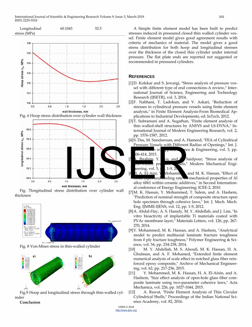
Fig. 5 load and B.C domain Results and validation Figs. (6 and 7) show stress distribution over thickness in the
thin cylinder, it is clearly observed that the change is little, this is because of the thickness is relatively small. A comparison between the hoop and longitudinal stresses induced in the cylinder wall is listed in Table 1. Von-Mises stress contour is illustrated in Fig. 8, the maximum and minimum value of stress at the ends of the cylinder. The mode of deformation for the closed cylinder ends is sever and dangers because the area of flat ends in the pressurized vessel is taking the most of the pressure. Hoop stress contour is shown in Fig. (9-a), whereas, longitudinal stress is shown in Fig. (9-b). The mesh is made medium coarse to reduce computational time. The prediction for longitudinal stress gives an increasing deference than that of hoop stress, this can be attributed to large deformation in the flat ends plate which dissipated the stress through it.
Table 1 Comparison between FEA and mechanics of mate-rial
Stress type FEA Mechanics of material
Hoop stress (MPa) 105.07 105
IJSER
International Journal of Scientific & Engineering Research Volume 9, Issue 3, March-2018 203 ISSN 2229-5518
IJSER © 2018 http://www.ijser.org
Longitudinal stress (MPa)
60.1043 52.5
Fig. 6 Hoop stress distribution over cylinder wall thickness
Fig. 7longitudinal stress distribution over cylinder wall
thickness
Fig. 8 Von-Mises stress in thin-walled cylinder
Fig.9 Hoop and longitudinal stress through thin-walled cyl-
inder Conclusion
A Simple finite element model has been built to predict stresses induced in pressured closed thin walled cylinder ves-sel. Finite element model gives good agreement results with criteria of mechanics of material. The model gives a good stress distribution for both hoop and longitudinal stresses over the thickness of the closed thin cylinder under internal pressure. The flat plate ends are reported not suggested or recommended in pressured cylinders.
REFERENCES [1] D. Kolekar and S. Jewargi, "Stress analysis of pressure ves-
sel with different type of end connections-A review," Inter-national Journal of Science, Engineering and Technology Research (IJSETR), vol. 3, 2014.
[2] F. Nabhani, T. Ladokun, and V. Askari, "Reduction of stresses in cylindrical pressure vessels using finite element analysis," in Finite Element Analysis-From Biomedical Ap-plications to Industrial Developments, ed: InTech, 2012.
[3] T. Subramani and A. Sugathan, "Finite element analysis of thin walled-shell structures by ANSYS and LS-DYNA," In-ternational Journal of Modern Engineering Research, vol. 2, pp. 1576-1587, 2012.
[4] S. Das, M. Sundaresan, and A. Hameed, "FEA of Cylindrical Pressure Vessels with Different Radius of Openings," Int. J. for Research in Applied Science & Engineering, vol. 3, pp. 406-414, 2015.
[5] A. Ibrahim, Y. Ryu, and M. Saidpour, "Stress analysis of thin-walled pressure vessels," Modern Mechanical Engi-neering, vol. 5, pp. 1-9, 2015.
[6] H. A. EI-Aini, Y. Mohammed, and M. K. Hassan, "Effect of mold types and cooling rate on mechanical properties of Al alloy 6061 within ceramic additives," in Second Internation-al conference of Energy Engineering; ICEE-2, 2010.
[7] M. K. Hassan, Y. Mohammed, T. Salem, and A. Hashem, "Prediction of nominal strength of composite structure open hole specimen through cohesive laws," Int. J. Mech. Mech. Eng. IJMME-IJENS, vol. 12, pp. 1-9, 2012.
[8] A. Abdal-Hay, A. S. Hamdy, M. Y. Abdellah, and J. Lim, "In vitro bioactivity of implantable Ti materials coated with PVAc membrane layer," Materials Letters, vol. 126, pp. 267-270, 2014.
[9] Y. Mohammed, M. K. Hassan, and A. Hashem, "Analytical model to predict multiaxial laminate fracture toughness from 0 ply fracture toughness," Polymer Engineering & Sci-ence, vol. 54, pp. 234-238, 2014.
[10] M. Y. Abdellah, M. S. Alsoufi, M. K. Hassan, H. A. Ghulman, and A. F. Mohamed, "Extended finite element numerical analysis of scale effect in notched glass fiber rein-forced epoxy composite," Archive of Mechanical Engineer-ing, vol. 62, pp. 217-236, 2015.
[11] Y. Mohammed, M. K. Hassan, H. A. El-Ainin, and A. Hashem, "Size effect analysis of open-hole glass fiber com-posite laminate using two-parameter cohesive laws," Acta Mechanica, vol. 226, pp. 1027-1044, 2015.
[12] A. Rawat, "Finite Element Analysis of Thin Circular Cylindrical Shells," Proceedings of the Indian National Sci-ence Academy, vol. 82, 2016.
IJSER
International Journal of Scientific & Engineering Research Volume 9, Issue 3, March-2018 204 ISSN 2229-5518
IJSER © 2018 http://www.ijser.org
[13] D. D. Babu and T. J. Balaji, "Theoritical and Finite El-ement Analysis of High Pressure Components," IOSR Jour-nal of Engineering, vol. 3, 2013.
[14] E. J. Hearn, Mechanics of Materials 2: The mechanics of elastic and plastic deformation of solids and structural materials: Butterworth-Heinemann, 1997.
[15] A. Ramsay, "Simulation Governance for the Expert Witness."
[16] N. S. Korim, M. Abdellah, M. Dewidar, and A. Abdelhaleem, "Crushable Finite Element Modeling of Me-chanical Properties of Titanium Foam," International Jour-nal of Scientific & Engineering Research, vol. 6, pp. 1221-1227, 2015.
IJSER