Embed Size (px)
Citation preview

Advanced Steel Construction Vol. 10, No. 4, pp. 463-475 (2014) 463
FINITE ELEMENT ANALYSIS OF CFRP STRENGTHENED STEEL HOLLOW SECTIONS UNDER TENSION
Sabrina Fawzia1 and Kaniz Shahanara2
1, 2 Science and Engineering Faculty, School of Civil Engineering and Built Environment, Queensland University of Technology, Brisbane 4000, Queensland, Australia
*(Corresponding author: E-mail: [email protected])
Received: 2 December 2013; Revised: 19 June 2014; Accepted: 24 June 2014
ABSTRACT: This paper presents a nonlinear finite element (FE) model for the analysis of very high strength (VHS) steel hollow sections wrapped by high modulus carbon fibre reinforced polymer (CFRP) sheets. The bond strength of CFRP wrapped VHS circular steel hollow section under tension is investigated using the FE model. The three dimensional FE model by Nonlinear static analysis has been carried out by Strand 7 finite element software. The model is validated by the experimental data obtained from Fawzia et al [1]. A detail parametric study has been performed to examine the effect of number of CFRP layers, different diameters of VHS steel tube and different bond lengths of CFRP sheet. The analytical model developed by Fawzia et al. [1] has been used to determine the load carrying capacity of different diameters of CFRP strengthened VHS steel tube by using the capacity from each layer of CFRP sheet. The results from FE model have found in reasonable agreement with the analytical model developed by Fawzia et al [1]. This validation was necessary because the analytical model by Fawzia et al [1] was developed by using only one diameter of VHS steel tube and fixed (five) number of CFRP layers. It can be concluded that the developed analytical model is valid for CFRP strengthened VHS steel tubes with diameter range of 38mm to 100mm and CFRP layer range of 3 to 5 layers. Based on the results it can also be concluded that the effective bond length is consistent for different diameters of steel tubes and different layers of CFRP. Three layers of CFRP is considered most effective wrapping scheme due to the cost effectiveness. Finally the distribution of longitudinal and hoop stress has been determined by the finite element model for different diameters of CFRP strengthened VHS steel tube. Keywords: Carbon fibre reinforced polymer (CFRP), Polymer, Finite element analysis (FEA), Analytical model, Joints and adhesive
1. INTRODUCTION Civil infrastructure in Australia represents a substantial amount of investment and is essential to the function and economic well-being of society. Current social and political pressure to maintain existing facilities in service for extended periods of time are high because of the involvement of huge cost of replacing existing facilities. Engineers are facing a rising level of aging infrastructure which has, in turn, led them to implement new materials and techniques to efficiently combat this problem. Using non-ferrous materials in the form of carbon fibre-reinforced polymer (CFRP) sheets as external reinforcement for VHS steel tubular structures can provide extensive benefits including weight savings, high strength to weight ratio, resistance to corrosion, flexibility to form all kinds of shapes and ease of handling during construction. The outstanding properties of CFRP such as high strength, high elastic modulus, light weight and good durability have made them a suitable alternative to steel in strengthening work. CFRP’s high strength-to-weight ratio has played a significant role in creating interest in strengthening, repair and rehabilitation of steel structures which has been demonstrated in a recent paper [2]. This review paper has covered wide area of CFRP strengthening of steel structure including hollow and concrete-filled steel tubes with external CFRP confinement. A comprehensive study on steel plates with double strap joint under tension has been done by the author Fawzia [3-6]. Although most columns should be in compression, sometimes they may be in tension under some load conditions such as wind uplift. Therefore research is needed for CFRP strengthened steel tube with double strap joint under tension load.

464 Finite Element Analysis of CFRP Strengthened Steel Hollow Sections under Tension
Experimental investigation on very high strength circular steel tubes strengthened by carbon fibre reinforced polymer subjected to axial tension has been conducted by Fawzia et al [1].VHS steel tube is popular due to its high strength (yield stress of around 1350 MPa and an ultimate strength of 1500 MPa), light weight and acceptable ductility [7]. High Modulus MBrace CF530 (640 GPa) and high strength epoxy Araldite 420 were used in the strengthening process of VHS steel tubes [1]. Several specimens with five layers of CFRP were tested in axial tension. Analytical model was developed to estimate the maximum load for a given CFRP arrangement based on the measured strain distribution across the CFRP layers. However, these experiments and the models were limited to one size of steel tube and 5 layers of CFRP [1]. In the present study an FE model has been developed for VHS steel hollow sections wrapped with CFRP sheets. The developed FE model was validated by the experimental data from Fawzia et at [1]. A detailed parametric study has been conducted by varying number of CFRP layers ( 3 to 5 layers), size of the steel hollow sections (diameters ranging 38mm to 100mm) and different bond length of CFRP sheet (5mm to 85mm). The results from FE models use to validate the analytical model developed by Fawzia et al [1] more widely. Finally the distribution of longitudinal and hoop stress has been established for different sizes of CFRP strengthened VHS steel tubes. 2. FINITE ELEMENT ANALYSIS (FEA) In the present study a series of finite element models for circular hollow steel sections wrapped with CFRP sheet composites is developed. The simulation was done in Strand7 finite element software by running nonlinear FE analysis solver to account for the nonlinear properties of the materials. In the models, a cylindrical coordinate system was selected. All materials were modelled as brick elements. Only a quarter of specimen was modelled for the symmetry of the sections. First cross sectional areas of all materials were created as plate element by adding nodes and then extruded along the longitudinal direction to represent the brick element. Figure 1(a) shows the schematic of experimental specimen of circular hollow section with double strap joints under tension and Figure 1(b) shows the corresponding FE model in the longitudinal direction. Two steel tubes were joined together using adhesive at the joint and 5 layers of CFRP were applied in the joint with the aid of adhesive. The CFRP length L1 was kept shorter than L2 to make failure happen in shorter bond length side. The total length of the specimen was 800mm, diameter was 38mm, and the thickness varies from 1.6mm to1.84mm. As no noticeable changes were reported because of small changes in steel tube thickness [4], the steel thickness of 1.84 mm was considered in all FE models for simplicity. In FE model different layers of CFRP was created as individual layers to find the load carrying capacity of each layer. The thickness of CFRP sheets was 0.19mm according to the manufacturer data [8]. In the experiments, it was difficult to maintain constant thickness of CFRP layers throughout the bond length as constant thickness of adhesive used cannot be maintained. Therefore, the thickness of adhesive layers is measured at different locations and the average thickness (0.09mm) was used in all FE models. Figure 2 represents the cross section of the sample in the FE model. Uniform displacement in the axial direction observed in the experimental test was applied in the FE model. This displacement data is factored in Strand 7 model to get a series of data to compare with experimental test until failure of the specimen. The FE model was validated using the experimental data from Fawzia et al.[1] and with the validated models a parametric study was carried out by varying number of CFRP layers (3 to 5), tube diameter (38 to 100mm) and CFRP bond length (5 to 85mm).

Sabrina Fawzia and Kaniz Shahanara 465
(a) Details of experimental specimen
(b)FE model representation (one fourth model)
Figure 1. Schematics View of the Experimental Specimen and FE Model (Longitudinal Section) 3. MATERIAL PROPERTIES In the present FE models, to match with the experimental investigation [1], MBrace high modulus fibre CF530, Araldite 420 adhesive and VHS steel tube were used. Similarly, all measured material properties from experimental study were used in the FE model. The summary of measured properties obtained from Fawzia et al [1] and Jiao and Zhao [9] are presented in Table 1. 4. FAILURE MODE AND ULTIMATE LOAD In order to determine the deformation clearly, Strand7 uses information about the nominal size of the structure and automatically provide a reasonable displacement scale. Fig. 3 shows, by using 5% displacement scale from Strand 7 software. The failure mode was fiber break at the joint which was exactly same as the experimental failure mode shows in Figure 4. The comparison of load carrying capacity between experimental [1] and FE results is shown in Table 2. It can be seen that there is reasonably good agreement between the experimental and the FE model results with mean =1.0325 and COV=0.1557.
200mm
L2 L1
Steel
5 layers of CFRP withAdhesive
200mm 400mm
L2 L1
Steel
5 layers of CFRP withAdhesive
400mm
800mm Length, 1.84 mm thick & dia varies from 38mm to 100mm
Steel Joint

466 Finite Element Analysis of CFRP Strengthened Steel Hollow Sections under Tension
(a) Cross section of the FE model
(b) One fourth model representation
(c) Detail of One fourth model representation
Figure 2: FE model representation (cross section)
See detail c

Sabrina Fawzia and Kaniz Shahanara 467
Table 1. Measured Material Properties by Fawzia et al [1] and Jiao and Zhao [9] CFRP Steel Adhesive Tensile modulus (GPa)
475
200
1.9
Tensile strength (MPa) 1016 1500 28.6
Table 2. Comparison of Experimental (Fawzia et al[1]) and FE Results for VHS Circular Steel Tube
Specimens Level
D mm
t (mm)
Experimental Results
FE Model Results Pu,FE / Pu,EXP
Remarks
Bond Length (mm)
Pu,EXP kN
Bond Length (mm)
Pu,FE kN
M1 38.24 1.84 85 84.9 85 73.06 0.8605 Fibre Break M3 38.30 1.79 65 74.1 65 73.53 0.9923 Fibre Break M4 38.10 1.60 62 77.5 62 73.36 0.9466 Fibre Break M5 38.27 1.74 50 67.3 50 72.73 1.0807 Fibre Break M6 38.10 1.60 40 54.8 40 70.28 1.2825 Fibre Break
Mean 1.0325 COV 0.1557
Figure 3. Failure Mode of the FE Specimen
5. EFFECTIVE BOND LENGTH The ultimate load carrying capacity against the bond length is plotted in Figure 5. In this figure comparison between experimental results from Fawzia et al [1] and the results of FE model from same bond length specimens is presented. It can be seen that the load carrying capacity reaches a plateau after the bond length exceeds a certain value. This length, beyond which no significant increase in load carrying capacity will occur, is called the effective bond length. It can also be seen from Figure 5 that the loads continue to increase with increase in the bond length. The ultimate load reaches a plateau after 50mm bond length. According to the definition of effective bond length, it can be concluded that effective bond length for 38mm diameter CFRP strengthened VHS steel tube is 50mm in both experimental [1] and FE model.

468 Finite Element Analysis of CFRP Strengthened Steel Hollow Sections under Tension
Figure 4. Failure Mode of the Test Specimen[1]
0
20
40
60
80
100
0 10 20 30 40 50 60 70 80 90
Load (kN)
Bond length (mm)
FE Result
EXP. Result
Effective bond length
Figure 5. Comparison of Experimental [1] and FE Results 6. PARAMETRIC STUDY VHS circular sections are used in situation where impact protection and extra strength is the critical requirement. It is also advisable that strength of VHS steel tube can be further increased by applying CFRP sheets. A parametric study has been conducted using finite element analysis. The main parameters studied are layers of CFRP, size of steel hollow sections and CFRP bond length.

Sabrina Fawzia and Kaniz Shahanara 469
6.1 Effect of Number of Layers of CFRP Sheets Finite element analysis has been carried out for 38mm diameter steel hollow sections by varying CFRP layers from 3 layers to 5 in order to find out the variation of load carrying capacity with the increase in CFRP layers. Also it is intended to examine the changes in effective bond length by varying the CFRP number of layers. The ultimate loads from FE analysis for 3, 4 and 5 CFRP layers shown in Table 3. The objective of this analysis is to check the impact of reducing the number of CFRP layers for cost effectiveness. A comparison has been done for 3 to 4 layers and 3 to 5 layers. The values of COV are 0.054 and 0.094 for 4 layers/ 3 layers and 5layers / 3layers respectively. This comparison is showing that there are no significant changes in load carrying capacity with the increment of CFRP layers. Figure 6 presents the ultimate load under different bond lengths for 38mm diameter of 3 (38_3layers), 4 (38_4layers) and 5 (38_5layers) CFRP layer models. The load carrying capacity will contribute slightly higher by increasing the number of CFRP layers although it is not significant. From Figure 6 it can be determined that the effective bond length of 50mm [1] for high modulus CFRP strengthened VHS steel tube is not changed by the increase of number of CFRP layers. Therefore it can be concluded that three layers of CFRP are cost effective and most efficient.
Table 3. Comparison of Load Carrying Capacity of Different Layers of CFRP for 38mm Diameter Steel Tube
D mm
t (mm)
Bond Length (mm)
FE Model Results Pu,FE kN 4 Layer/ 3 Layer
5 Layer/ 3Layer
3 Layer 4 Layer 5 Layer
38.0 1.84 85 55.96 64.52 73.06 1.153 1.306 38.0 1.84 75 55.79 64.46 73.39 1.155 1.315 38.0 1.84 65 56.47 64.30 73.53 1.139 1.302 38.0 1.84 55 56.42 65.85 73.05 1.167 1.295 38.0 1.84 50 56.36 65.68 72.73 1.165 1.290 38.0 1.84 45 56.21 65.43 71.42 1.164 1.271 38.0 1.84 30 54.68 60.93 67.01 1.114 1.225 38.0 1.84 15 46.25 47.30 47.78 1.023 1.033 38.0 1.84 5 17.26 17.27 17.27 1.001 1.001
Average 1.12 1.226
COV 0.054 0.094
6.2 Effect of Different Diameters of VHS Steel Circular Tube Commercially available size of VHS circular sections are varies from 19mm to 100mm. Therefore FE model has been carried out by using four different diameters (38mm, 50mm, 75mm and 100mm) to check the effect of different sizes of CFRP strengthened VHS circular hollow section. Table 4 shows the list of ultimate load carrying capacity for 38mm, 50mm, 75mm and 100mm diameters VHS circular hollow sections. It can be concluded from the Table 4 that the load carrying capacity increases proportionally with the increase of diameter of VHS steel hollow sections. However, as can be seen in Figure 7 the effective bond length is not affected by the increase of diameter. The effective bond length remains 50mm for different sizes (38mm, 50mm, 75mm and 100mm) of CFRP strengthened VHS steel tube.
470 Finite Element Analysis of CFRP Strengthened Steel Hollow Sections under Tension
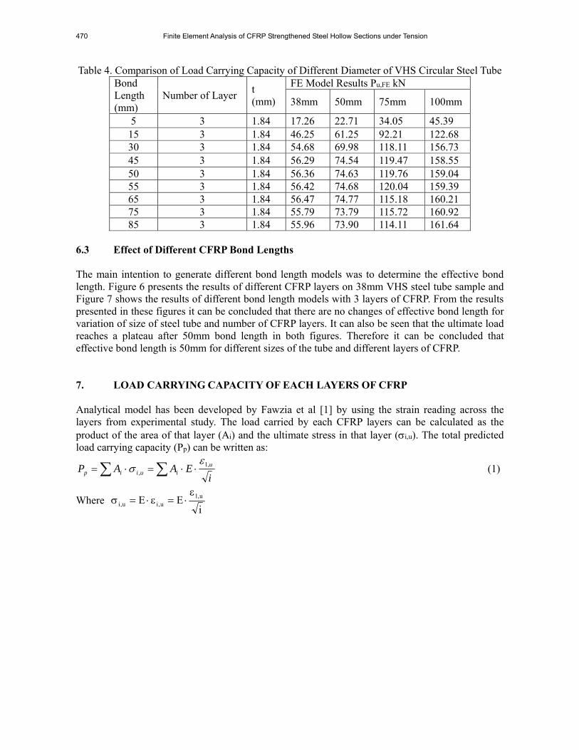
Table 4. Comparison of Load Carrying Capacity of Different Diameter of VHS Circular Steel Tube Bond Length (mm)
Number of Layer t (mm)
FE Model Results Pu,FE kN
38mm 50mm 75mm 100mm
5 3 1.84 17.26 22.71 34.05 45.39 15 3 1.84 46.25 61.25 92.21 122.68 30 3 1.84 54.68 69.98 118.11 156.73 45 3 1.84 56.29 74.54 119.47 158.55 50 3 1.84 56.36 74.63 119.76 159.04 55 3 1.84 56.42 74.68 120.04 159.39 65 3 1.84 56.47 74.77 115.18 160.21 75 3 1.84 55.79 73.79 115.72 160.92 85 3 1.84 55.96 73.90 114.11 161.64
6.3 Effect of Different CFRP Bond Lengths The main intention to generate different bond length models was to determine the effective bond length. Figure 6 presents the results of different CFRP layers on 38mm VHS steel tube sample and Figure 7 shows the results of different bond length models with 3 layers of CFRP. From the results presented in these figures it can be concluded that there are no changes of effective bond length for variation of size of steel tube and number of CFRP layers. It can also be seen that the ultimate load reaches a plateau after 50mm bond length in both figures. Therefore it can be concluded that effective bond length is 50mm for different sizes of the tube and different layers of CFRP. 7. LOAD CARRYING CAPACITY OF EACH LAYERS OF CFRP Analytical model has been developed by Fawzia et al [1] by using the strain reading across the layers from experimental study. The load carried by each CFRP layers can be calculated as the product of the area of that layer (Ai) and the ultimate stress in that layer (i,u). The total predicted load carrying capacity (Pp) can be written as:
i
EAAP uiuiip
,1,
(1)
Where i
EE u,1u,iu,i

Sabrina Fawzia and Kaniz Shahanara 471
0
20
40
60
80
0 10 20 30 40 50 60 70 80 90 100
Load (kN)
Bond Length (mm)
38_5layer
38_4layer
38_3layer
Effective bond length
Figure 6. Effect of Number of CFRP Layers
0
20
40
60
80
100
120
140
160
180
0 10 20 30 40 50 60 70 80 90 100
Load (kN)
Bond Length (mm)
38_3layer
50_3layer
75_3layer
100_3 layer
Effective bond length (mm)
Figure 7. Effect of Different Size of Circular Steel Sections in FE Results

472 Finite Element Analysis of CFRP Strengthened Steel Hollow Sections under Tension
The value of 1,u is taken as the maximum strain (2113 microstrain) obtained in tensile tests of CFRP with epoxy and the Young’s modulus E is taken as 457,900 MPa [1]. The above analytical model has been used to calculate the ultimate load carrying capacity for each layer of CFRP. Table 5 and Figure 8 present the load carrying capacity of 1st, 2nd and 3rd layers of CFRP on 38, 50, 75 and 100 mm VHS circular steel tube. It can be seen that the first CFRP layer is carrying larger load than others. Once this layer carried the maximum capacity then the load is transferred to 2nd layer and so on. Finally the third layer is carrying very minimum load.
Table 5. Load Carrying Capacity of Different CFRP Layers of 38, 50,75 and 100 mm
dia VHS Circular Steel Tube Layer number
38mm dia 50mm dia 75mm dia 100mm dia
Ultimate load (kN)
Ultimate load (kN)
Ultimate load (kN)
Ultimate load (kN)
1 22.92 30.12 45.13 60.14 2 16.37 21.46 32.07 42.68 3 13.50 17.66 26.32 34.98 Total 52.79 69.24 103.52 137.80
The first layer is carrying almost 43% of total load, 2nd layer is carrying 30% and 3rd layer is carrying only 25% load. From this finding it can be concluded that 3 layers of CFRP can be considered as the most efficient combination. Use of 4th and 5th layers of CFRP will only slightly increase the ultimate load which will be negligible compared to the 3 layers capacity. Table 6 shows the comparison of analytical model and FE Model for load carrying capacity of different diameters of CFRP strengthened VHS circular steel tube. The analytical model has reasonable agreement with the FE model as the COV of Table 6 is 0.04. It can be concluded that the analytical model to predict the load carrying capacity by using the ultimate strain of each layers of CFRP is applicable to 38mm to 100mm range of CFRP strengthened VHS steel tubes.
Table 6. Comparison of Analytical Model and FE Model for Load Carrying Capacity of Different Diameter of VHS Circular Steel Tube Diameter Analytical FE FE/Analytical Ultimate load Ultimate load mm kN kN 38 52.79 56.36 1.07 50 69.24 74.63 1.08 75 103.52 119.76 1.16 100 137.80 159.04 1.15 mean 1.11 COV 0.04
8. DISTRIBUTION OF LONGITUDINAL STRESS Figure 9 shows the distribution of longitudinal stress at the joint for CFRP strengthened 38mm, 50mm, 75mm and 100mm diameter VHS steel hollow sections. In this figure, longitudinal stress of the first or bottom CFRP layer is shown as the bottom layer of CFRP is carrying the highest load. The horizontal axis of Figure 9 is a factor which has been applied to the FE model to represent the applied load. It can be seen that the longitudinal stress is increasing with the increase of the factor,

Sabrina Fawzia and Kaniz Shahanara 473
which means that longitudinal stress increases with the increase of the load. From Figure 9 it can be seen that longitudinal stress is increasing with the increase of the size of steel tube. Therefore it can be concluded that increasing the size of steel tube will increase the longitudinal stress at the joint of double strap joint.
0
10
20
30
40
50
60
70
0 1 2 3 4
Ultimate load (kN)
CFRP layer number
38
50
75
100
Figure 8. Comparison of Load Carrying Capacity of Different Layers of CFRP for 38, 50, 75 and
100 mm dia CFRP Strengthened VHS Steel Tube
Figure 9. Distribution of Longitudinal Stress for Different Diameter CFRP Strengthened
VHS Steel Hollow Section

474 Finite Element Analysis of CFRP Strengthened Steel Hollow Sections under Tension
9. DISTRIBUTION OF HOOP STRESS Figure 10 shows the distribution of hoop stress for 38mm, 50mm, 75mm and 100mm diameter VHS steel hollow section double strap joints. Determination of the distribution of hoop stress is really important for circular hollow section. Figure 10 is representing the hoop stress distribution at the first or bottom CFRP layer at the joint of double strap joint. The horizontal axis of Figure 10 is a factor which has been applied to the FE model to represent the applied load. It can be seen that the hoop stress is increasing with the increase of the factor, which means that hoop stress is increasing with the increase of the applied load. It can be seen that the maximum hoop stress at the joint for 38mm, 50mm, 75mm and 100mm diameter samples are 50, 85, 97 and 113MPa respectively. Therefore it can be concluded from Figure 10 that increasing the size of steel tube will increase the hoop stress capacity of CFRP strengthened steel hollow tube.
Figure 10. Distribution of Hoop Stress for Different Diameter CFRP Strengthened
VHS Steel Hollow Section 10. SUMMARY In this paper the results from finite element analysis of CFRP strengthened VHS steel tube double strap joint specimens under tension are presented. The investigated variables are CFRP bond lengths, number of CFRP layer, and size of circular steel hollow sections. The findings from the parametric studies are summarised as follows: 1. Load carrying capacity does not change significantly with the increment of bond length after 50mm for CFRP strengthened VHS steel tube double strap joint. Therefore it can be concluded that the effective bond length is 50mm for CFRP strengthened VHS steel tubes. 2. There was no change in effective bond length for variation of CFRP layers. Load carrying capacity increased with the increase in number of CFRP layers but the improvement was not significant. Therefore it can be concluded that three layers of CFRP is the most effective for CFRP strengthened VHS steel tubes. Effective bond length of CFRP strengthened VHS steel tubes is 50mm for different number of CFRP layers (3 to 5 layers). 3. There was no change in effective bond length for different diameters of CFRP strengthened VHS steel hollow sections. Load carrying capacity increased by increasing the size of steel hollow section but the change was not significant. Effective bond length of CFRP strengthened VHS steel specimens is 50mm for different sizes (38mm to 100mm) of CFRP strengthened VHS steel tubes. 4. Three layers of CFRP do not carry same load for a given CFRP arrangement. The first or bottom layer of CFRP carry about 43% load, 2nd layer carry 30% and 3rd layer carry 25% load for the double strap joint investigated in this research.

Sabrina Fawzia and Kaniz Shahanara 475
5. Three layers of CFRP are cost effective and most efficient layers for CFRP strengthened VHS steel hollow tube. 6. Increasing the size of steel tube will increase the longitudinal stress and hoop stress at the joint of steel hollow section double strap joint. NOTATION Ai = Product of the area of the layer E = Young’s modulus of CFRP L1 = Short bond length (mm) L2 = Long bond length (mm) Pu,EXP = Ultimate load of experiment Pu,FE = Ultimate load of FE model Pp =The total predicted load carrying capacity i,u =The ultimate stress in the ith layer i,u =The ultimate strain in the ith layer 1,u =The ultimate strain in the first (bottom) layer εi = Strain in the ith layer I = Layer number REFERENCES [1] Fawzia, S., Al-Mahaidi, R., Zhao, X.L., and Rizkalla, S., “Strengthening of Circular Hollow
Steel Tubular Sections using High Modulus CFRP Sheets”, Construction and Building Materials, 2007, Vol. 21, No. 4, pp. 839-845.
[2] Teng, J.G., T.B. Yu and Fernando, D., “Strengthening of Steel Structures with Fiber-reinforced Polymer Composites”, Journal of Constructional Steel Research, 2012, Vol. 78, pp.131–143.
[3] Fawzia, S. “Evaluation of Shear Stress and Slip Relationship of Composite Lap Joints”, Composite Structures, 2013, 100, pp.548-553.
[4] Fawzia, S., Zhao, X.L. and Al-Mahaidi, R., “Bond–slip Models for Double Strap Joints Strengthened by CFRP”, Composite Structures, 2010, Vol. 92, No. 9, pp. 2137-2145.
[5] Fawzia, S., Al-Mahaidi, R. and Zhao, X.L., “Experimental and Finite Element Analysis of a Double Strap Joint between Steel Plates and Normal Modulus CFRP”, Composite Structures, 2006, Vol. 75, No. 1-4, pp. 156-162.
[6] Fawzia, S., Zhao, X.L., Al-Mahaidi, R. and Rizkalla, S., “Bond Characteristics between CFRP and Steel Plates in Double Strap Joints”, Advanced Steel Construction-An International Journal, 2005, Vol. 1, No. 2, pp. 17–28.
[7] Zhao, X.-L., “Section Capacity of Very High Strength (VHS) Circular Tubes under Compression”, Thin-Walled Structures 2000, Vol. 37, No. 3, pp. 223-240.
[8] BASF Construction Chemicals Australia Pty Ltd., “Mbrace Fibre CF 530, Technical Data Sheet”, 7 Kingston Town Close, Oakleigh, Australia.
[9] Jiao, H. and Zhao, X.L., “Material Ductility of Very High Strength (VHS) Circular Steel Tubes in Tension”, Thin-Walled Structures, 2001, Vol. 39, No. 11, pp. 887–906.