Embed Size (px)
Citation preview

823
Journal of Engineering Sciences
Assiut University
Faculty of Engineering
Vol. 43
No. 6
November 2015
PP. 823 – 836
PERFORMANCE OF MASONRY ARCHES
STRENGTHENED WITH CFRP SANDWICH
Ahmed M. Anwar
Construction Research Institute, Cairo, Egypt
(Received 28 September 2015; Accepted 20 October 2015)
ABSTRACT
Upgrading and strengthening of structural and architectural arches for functionality purpose as well
as for conversation of cultural heritage are of great concern. In the current research, Carbon Fiber
Reinforced Polymers (CFRP) was used to raise the structural integrity of masonry arches. The
strengthening efficiency and structural performance of arches having semi-circle and quarter circle
shapes covering the same opening span were studied. Strengthening by fitting CFRP sheets in a
Sandwich form was investigated. At the beginning, CFRP sheets alone were directly applied along
the intrados and extrados surfaces of the arches. Secondly, the same technique was adopted but after
adding a thin layer of plain concrete at the extrados surface prior to the application of the external
layer of CFRP. Six Arches with different strengthening configurations were prepared.
Comprehensive static and dynamic evaluations were conducted. The efficiency of strengthened
arches with semi-circle shape was found, in general, better than arches of quarter circle shape.
CFRP works on prevention of the formation of hinges in either the extrados or intrados surfaces of
the arches, and consequently improving the performance of arches during failure. The load carrying
capacity was also enhanced significantly. The addition of thin plain concrete layer was found
significant in distributing the applied load and preventing the conventional slippage failure mode at
interface between mortar and bricks. The obtained dynamic modal parameters of the examined
arches due to excitation with light impact hummer at the crest of strengthened arches showed
enhancement in their dynamic performance as well.
Keywords: Masonry Arches, CFRP strengthening, Physical modeling, Collapse, Damage,
Dynamic analysis.
1. Introduction
Masonry arches played an important role in construction of a wide range of hydraulic
structures in Egypt. Arches constitute not only the fundamental constructive element in
transmitting the traffic loads to the carrying systems but also are of considerable historical
and architectural importance. Aging problems, accidental problems and/or the need to
increase arch carrying capacity are among the challenges that should be put into focus. In
addition, masonry arches are scarcely resistant to horizontal loads, and therefore highly
vulnerable to seismic actions. Strengthening or repairing of such structures is not always an
easy task. The compatibility and adequacy of the chosen material should be studied probably
in such a way that the expected brittle failure of masonry should be prevented. Moreover, in

824
JES, Assiut University, Faculty of Engineering, Vol. 43, No. 6, November 2015, pp. 823 – 836
hydraulic structures the used material should be of durable, light weight, high tensile strength
and does not occupy additional volume for hydraulic and navigation aspects.
It has been investigated, by many researchers, the possibility of using fiber reinforced
polymers (FRP) sheets directly to masonry constructions [1, 2, 3]. The load carrying
capacity of masonry arches and vaults can be increased by modifying the collapse
mechanism of the structure using strengthening materials externally bonded at the intrados
or the extrados surfaces [4]. Cancelliere et al. [1] reported that strengthening the arch with
FRP at the extrados surface only was capable to change the failure mechanism from
formation of hinges to collapse due to the limit strength of the constituent materials. Tao et
al. [2] studied the effect of using FRP as a repair material applied on the intrados of a large
model masonry arch bridge of two vents. Juntao Kang et al. [5] reported that the internal
forces in a double curved arch bridge have been favorably redistributed by adding
reinforced concrete layer at specific portions of the extrados surface of the bridge. Anania
et al. [6], introduced a technique based on the use of the composite CFRP applied using a
calibrated shape ‘‘Ω-Wrap’’ around a high resistance mortar core realized at the barrel
vault extrados as a supporting rib.
Angelo et al. [7] studied analytically the effect of using composite unbonded tendons to
the extrados surface of semicircle arch as another alternative for arch strengthening.
Furthermore, Francesca et al. [8] studied the behavior of single bricks and small masonry
pillars strengthened by means of fabric reinforced cementitious matrix systems made with
glass-fiber grids. Garmendia et al. [9] showed that using a basalt textile embedded in an
organic matrix known as Basalt Textile-Reinforced Mortar as a reinforcement system for
stone arches enhanced their load-bearing capacity and ductility.
Maruccio et al. [10] conducted advanced non-linear simulations of experimental test
results to study the interfacial behavior of brittle substrate (masonry) and the thin elastic
sheet (FRP) used for strengthening historical arches and vaults. Spinella et al. [11] showed
results of in-situ tests carried out on ancient masonry full-scale arch walls after retrofitting
by pre-tensioned stainless steel ribbons. Borri et al. [12] reported the effectiveness of using
glass and carbon FRP plates placed at the intrados of masonry arches.
Few researches dealt with the dynamic behavior of strengthened arches. In fact,
dynamic tests are nondestructive and cause no damage to these structures. Calik et al. [3]
identified the dynamic characteristics of the masonry vault before and after repair, using
steel fasteners at the peak of vaults. Bayraktar et al. [13] conducted formal modal analysis
on eight historical masonry stone arch bridges with different spans to determine their
natural frequencies, damping ratios and mode shapes. The dynamic behavior and modal
parameters of brick masonry arches strengthened with prepreg polymer composites were
experimentally and numerically studied by Cakir and Uysal [14]. Xie et al. [15] used
CFRP to strengthen a concrete buried arch against blast applied at its soffit surface only.
In the current research, two different shapes of masonry arches were investigated; the
first was semi-circle while the other was quarter circle. The two sets of arches were
subjected to different strengthening scenarios. The strengthening techniques depend
mainly on using CFRP sheets in the form of a sandwich, i.e. covering bricks at both upper
and lower surfaces simultaneously. This methodology was uncovered in previous works.
The arches were evaluated using dynamic and static tests. Modal parameters, load carrying
capacity, and failure mechanism for each condition were obtained and discussed. In

825
Ahmed M. Anwar, performance of masonry arches strengthened with CFRP sandwich
addition, numerical modelling using finite element analysis was conducted to validate the
obtained modal parameters for the examined arches.
2. Experimental program
2.1 Materials
In the current research, masonry arches constituted of red clayey solid brick units
bonded together with cement mortar. Each brick unit was of dimensions (length x width x
thickness) equal to (180x80x60 mm). The average binding mortar thickness was 10 mm.
The physical properties for both materials were investigated at their separate and combined
states. The compressive strength test was conducted on one unit of bricks laid horizontally,
whereas, a mortar cube of dimensions (70x70x70 mm) was used for this purpose. The
flexure strength was determined by adopting four points load test on one brick unit. While
mortar specimens of dimensions (160x40x40 mm) were used for both flexure and splitting
tests. For the purpose of strengthening, sheets of CFRP as well as a layer of plain concrete
(P.C.) of 50 mm thickness were used. Uni-directional CFRP sheets, 0.111 mm thickness
was used. As per the manufacturer, the tensile strength, and modulus of elasticity of CFRP
are 3400 N/mm2, and 2.45x10
5 N/mm
2, respectively. CFRP was pasted on the required
surfaces using two compounds epoxy recommended and supplied by manufacturer. The
Physical properties of the Epoxy resin are shown in Table 1. For plain concrete, cylinders
of diameter, 100 mm, and height, 200 mm, were prepared for compression and splitting
tests. Whereas, prisms of dimensions (500 x 100 x 100 mm) were set for four points
flexure test. Table 2, shows the physical properties of the used materials.
Table 1. Physical Properties of the Bonding Epoxy
Color Specific
Gravity
Flexure Strength
(N/mm2)
Tensile Strength
(N/mm2)
Shear Strength
(N/mm2)
Viscosity
(MPa.S)
Blue 1.17 + 0.1 40 30 10 20000
Table 2.
Physical Properties of used Materials
Type of
Specimens
Unit Weight
(KN/m3)
Compressive
Strength
(N/mm2)
Flexure Strength
(N/mm2)
Indirect Tensile
Strength
(N/mm2)
Clayey
Bricks
21.0 3.5 0.7 --
Cement
Mortar
22.5 15.0 2.5 1.3
Plain
Concrete
23.1 23.0 2.9 2.1
In addition, sets of combined bricks and mortar were prepared to determine the properties
of their combined actions. Firstly, the compressive strength of a set of three overlaying bricks
was examined (Figure 1a). It was found that compressive strength was 3.22 N/mm2.
Secondly, the interfacial shear strength between the mortar and the bricks were also
examined experimentally. Three bricks were joined in such a way that the middle brick was
oriented ahead of the two edge blocks with an overlap splice length of 100 mm (Figure 1b).
The interfacial shear strength between mortar and bricks were found 0.74 N/mm2. For all
these combined samples, replicates of three were prepared for examination.

826
JES, Assiut University, Faculty of Engineering, Vol. 43, No. 6, November 2015, pp. 823 – 836
Fig. 1. Masonry Specimens used for: a) Compression Test, and b) Interfacial Shear Test.
2.2 Specimens preparation
2.2.1 Masonry beams At the beginning, the suggested sandwich strengthening by applying, simultaneously,
CFRP sheets at the upper and lower surfaces of masonry beams was conducted. Seven bricks
were arranged along their width and bonded together with mortar to form masonry beams.
The total flexure span was adjusted to 420 mm. Replicates of three were prepared to examine
the efficiency of the suggested strengthening. The flexure strength of the beams was
examined under four points flexure test. Figure 2, shows the specimens with different
strengthening configurations. First, the specimen with no strengthening (hereinafter referred
to as “MAS”) was examined and kept as a control for comparison. Furthermore, another two
sets were prepared to simulate the strengthening conditions that will be used later for the
masonry arches. The first was to apply CFRP directly on both the soffit and upper surfaces of
masonry beam (hereinafter referred to as “MAS_CFRP”). For the last strengthening
configuration (hereinafter referred to as “MAS_CFRP_CONC”), a thin layer of plain
concrete was added prior to the application of CFRP at the upper surface of the beam.
In fact, plain concrete was added in the second day of constructing the masonry beams
and left in normal room temperature to cure together by daily sprinkling of water on them.
Moreover, CFRP was applied after 21 days of concrete casting. The required surface was
polished followed by water and air cleaning. The masonry beams were kept for complete
dryness for one day. Finally, epoxy (hardener and resign) was applied in two coats – above
and underneath the CFRP sheet. Special steel roller was used to ensure the absence of any
air voids and ensure full contact. The specimens were kept to cure together till the end of
the 28 days. The upper CFRP sheets were used to conform to the same strengthening
condition used with arches, as the target was to investigate the enhancement in the group
actions of masonry strengthened in sandwich form.
Fig. 2. Different Strengthening Configurations for Masonry Beams
2.2.2 Masonry arches Masonry arches with different geometries and subjected to different strengthening
condition were chosen for examination. Mainly, two basic groups of arches with different
geometries were investigated. The first was the semi-circle arch (S-Arch) while the second
827
Ahmed M. Anwar, performance of masonry arches strengthened with CFRP sandwich
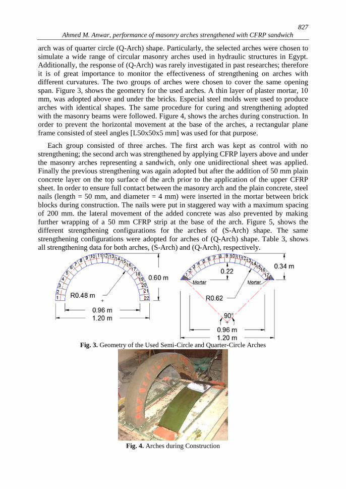
arch was of quarter circle (Q-Arch) shape. Particularly, the selected arches were chosen to
simulate a wide range of circular masonry arches used in hydraulic structures in Egypt.
Additionally, the response of (Q-Arch) was rarely investigated in past researches; therefore
it is of great importance to monitor the effectiveness of strengthening on arches with
different curvatures. The two groups of arches were chosen to cover the same opening
span. Figure 3, shows the geometry for the used arches. A thin layer of plaster mortar, 10
mm, was adopted above and under the bricks. Especial steel molds were used to produce
arches with identical shapes. The same procedure for curing and strengthening adopted
with the masonry beams were followed. Figure 4, shows the arches during construction. In
order to prevent the horizontal movement at the base of the arches, a rectangular plane
frame consisted of steel angles [L50x50x5 mm] was used for that purpose.
Each group consisted of three arches. The first arch was kept as control with no
strengthening; the second arch was strengthened by applying CFRP layers above and under
the masonry arches representing a sandwich, only one unidirectional sheet was applied.
Finally the previous strengthening was again adopted but after the addition of 50 mm plain
concrete layer on the top surface of the arch prior to the application of the upper CFRP
sheet. In order to ensure full contact between the masonry arch and the plain concrete, steel
nails (length = 50 mm, and diameter = 4 mm) were inserted in the mortar between brick
blocks during construction. The nails were put in staggered way with a maximum spacing
of 200 mm. the lateral movement of the added concrete was also prevented by making
further wrapping of a 50 mm CFRP strip at the base of the arch. Figure 5, shows the
different strengthening configurations for the arches of (S-Arch) shape. The same
strengthening configurations were adopted for arches of (Q-Arch) shape. Table 3, shows
all strengthening data for both arches, (S-Arch) and (Q-Arch), respectively.
Fig. 3. Geometry of the Used Semi-Circle and Quarter-Circle Arches
Fig. 4. Arches during Construction

828
JES, Assiut University, Faculty of Engineering, Vol. 43, No. 6, November 2015, pp. 823 – 836
2.3 Test setup
The arches were examined first statically. A concentrated load was applied at the crest
of the arch. Both load and mid-span deflections were measured. The load-deflection plots
for each strengthening condition were put into glance and compared together. The failure
mode was also reported. On the other hand, dynamic evaluation for all arches was
performed. All the arches were subjected to vertical impulse by a light impact hammer
applied at the crest of the arches. For each strengthening condition, the test was performed
twice, before and after strengthening. Acceleration time histories were collected by means
of piezoelectric accelerometer vertically placed at the top of the arch. The collected data
were filtered and analyzed using Fast Fourier Transformation (FFT) technique. The natural
frequencies were obtained and compared with each other. In the current application, the
sampling rate was selected to be 5000 Hz. This allowed the capturing up to the second
mode for both arches with sufficient resolution. Figures 6a, and b, show the test procedure
for static and dynamic tests, respectively.
Fig. 5. Typical Strengthening Configurations for (S-Arch)
Table 3.
Description of Strengthening Configuration for Investigated Arches
Specimen Strengthening Configuration
S-Arch Semi-circle Arch with no strengthening
S-Arch-CFRP Semi-circle Arch with CFRP sheets at both the extrados and intrados surfaces
S-Arch-CFRP-Conc Semi-circle Arch with 50 mm concrete at the intrados followed by CFRP
sheets at both the extrados and intrados surfaces
Q-Arch Quarter-circle Arch with no strengthening
Q-Arch-CFRP Quarter-circle Arch with CFRP sheets at both the extrados and intrados surfaces
Q-Arch-CFRP-Conc Quarter-circle Arch with 50 mm concrete at the intrados followed by CFRP
sheets at both the extrados and intrados surfaces
Fig. 6. a) Static Loading Test Setup, and b) Dynamic Testing of Masonry Arches

829
Ahmed M. Anwar, performance of masonry arches strengthened with CFRP sandwich
3. Results and discussions
3.1 Static test results
3.1.1 Masonry beams For all masonry beams, the load, strain and deflection at the mid-span of all beams were
monitored and compared. Figures 7a, and b show the load-deflection, and load-strain
curves for all tested beams, respectively. It was noted that the load carrying capacity of the
beam strengthened with CFRP only (MAS_CFRP), and with both CFRP and concrete
together (MAS_CFRP_CONC), were 3.41 and 10.9 times that of the control specimen
(MAS). The slope of the load- deflection curves showed the high stiffness of
(MAS_CFRP_CONC) over (MAS_CFRP). Moreover, the much higher strain obtained in
(MAS_CFRP_CONC) indicated the enhancement of ductility of the specimen over the rest
of the examined beams. It was also clear that the failure mode of (MAS) was pure flexure
occurred in the middle third of the beam at the interface joint between mortar and bricks.
Actually, the current strengthening techniques overcame the unfavorable flexure failure
due to the weakness of the mortar-masonry interface in transmitting the tensile forces. The
use of sandwich like CFRP strengthening played an important role in preserving the
integrity of the masonry beams; the fibers along the tensile soffit retarded the generation of
cracks till certain strain after which the CFRP bears all the tensile stress till failure
occurred. Whereas, the fibers along the compression surface slightly enhance the ductility
of the beam. It was noticed that the conventional flexure failure was prevented. Shear
failure between mortar and bricks occurred instead. Thus, the sandwich like CFRP
strengthening worked as a wrap to the joined blocks of bricks and optimize the group
action of bricks till failure occurred. In order to overcome both flexure and/or interfacial
shear failure at the brick-mortar interface; a thin layer of plain concrete was added prior to
application of CFRP at the compression side. It was also shown that adding plain concrete
layer played an important role in improving the shear resistance, redistributing the load
among all the bricks, and enhancing the overall stiffness of the masonry beams, i.e. it gave
the sandwich a sort of rigidity. The failure of specimen (MAS_CFRP_CONC) showed that
the failures occurred previously has been replaced by a pure shear failure in the brick unit
itself followed by interfacial debonding of plain concrete over the cracked portion of
bricks. Figure 8, shows the mode of failure occurred for masonry beams.
Fig. 7. (a) Load-Deflection and (b) Load-Strain Curves for Masonry Beams
830
JES, Assiut University, Faculty of Engineering, Vol. 43, No. 6, November 2015, pp. 823 – 836
Fig. 8. Failure Modes for Masonry Beams with (a) no Strengthening, (b) CFRP Sandwich
Strengthening, and (c) Concrete and CFRP Sandwich Strengthening
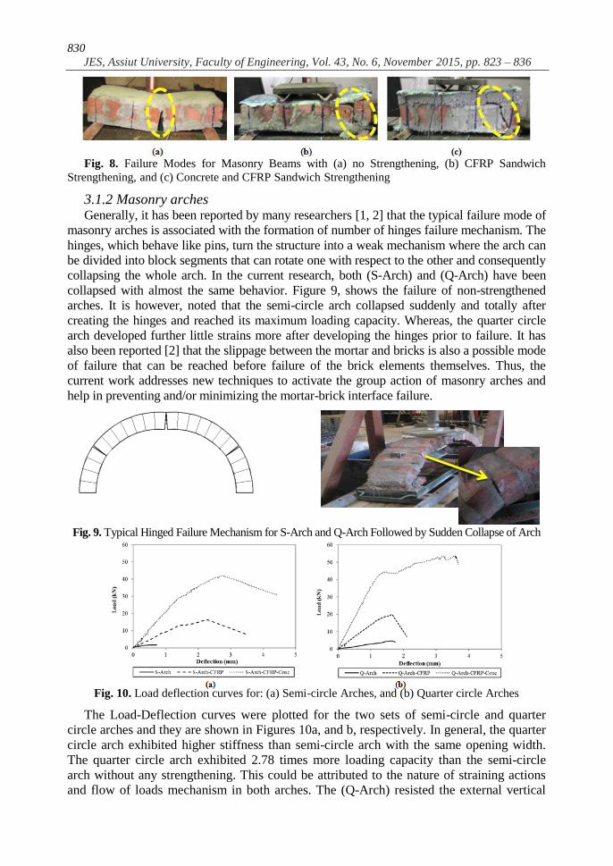
3.1.2 Masonry arches Generally, it has been reported by many researchers [1, 2] that the typical failure mode of
masonry arches is associated with the formation of number of hinges failure mechanism. The
hinges, which behave like pins, turn the structure into a weak mechanism where the arch can
be divided into block segments that can rotate one with respect to the other and consequently
collapsing the whole arch. In the current research, both (S-Arch) and (Q-Arch) have been
collapsed with almost the same behavior. Figure 9, shows the failure of non-strengthened
arches. It is however, noted that the semi-circle arch collapsed suddenly and totally after
creating the hinges and reached its maximum loading capacity. Whereas, the quarter circle
arch developed further little strains more after developing the hinges prior to failure. It has
also been reported [2] that the slippage between the mortar and bricks is also a possible mode
of failure that can be reached before failure of the brick elements themselves. Thus, the
current work addresses new techniques to activate the group action of masonry arches and
help in preventing and/or minimizing the mortar-brick interface failure.
Fig. 9. Typical Hinged Failure Mechanism for S-Arch and Q-Arch Followed by Sudden Collapse of Arch
Fig. 10. Load deflection curves for: (a) Semi-circle Arches, and (b) Quarter circle Arches
The Load-Deflection curves were plotted for the two sets of semi-circle and quarter
circle arches and they are shown in Figures 10a, and b, respectively. In general, the quarter
circle arch exhibited higher stiffness than semi-circle arch with the same opening width.
The quarter circle arch exhibited 2.78 times more loading capacity than the semi-circle
arch without any strengthening. This could be attributed to the nature of straining actions
and flow of loads mechanism in both arches. The (Q-Arch) resisted the external vertical

831
Ahmed M. Anwar, performance of masonry arches strengthened with CFRP sandwich
applied force by internal axial compression force that transmits the loads to the support
causing big horizontal reactions. Whereas, the (S-Arch) the external load forced the arch to
deform laterally and consequently accelerated the formation of hinges.
In general, the load carrying capacity of all examined arches achieved much higher values
than their control specimens. For Semi-circle arches, it was noted that the load carrying
capacity for (S-Arch-CFRP) and (S-Arch-CFRP-Conc) exerted 9.72, and 24.96 times more
than the original arch with no strengthening (S-Arch). Whereas, the quarter circle arches (Q-
Arch-CFRP) and (Q-Arch-CFRP-Conc) reached 4.25, and 11.39 times the load carrying that
of the control (Q-Arch). It was also clear that the efficiency of strengthening of semi-circle
arches was almost more than twice those of the quarter circle arches.
The modes of failure of the strengthened arches are shown in Figure 11. It was clear that the
formation of multi-hinges mechanism was avoided and a better arch performance was achieved.
For (S-Arch-CFRP), the crack started in the vicinity of the load at the mortar-brick interface
causing concentration of stresses in the CFRP sheet at the intrados surface followed by interfacial
debonding and this matched with previously reported [16]. Successively, slippage between
mortar-brick interface at the left base of the arch due to horizontal force was captured. For (Q-
Arch-CFRP), no horizontal slippage was monitored; however, interfacial shear failure at mortar-
brick interface occurred at vicinity of the load till the intrados surface leading to interfacial
debonding of CFRP sheet. For (S-Arch-CFRP-Conc), the crack started from the load application
point and thoroughly cut the brick unit itself in shear mode till reaching the intrados surface
where debonding of CFRP sheet occurred. The performance of (Q-Arch-CFRP-Conc) exhibited
the best performance among all strengthening conditions. Occurrence of interfacial debonding
has no longer being existed, group of flexure-shear cracks starting from load application point
through the plain concrete, crossing bricks and mortar till the right support. The shear failure in
bricks revealed that the failure started after reaching the maximum capacity of the constitutional
materials. This indicated that this strengthening mechanism worked in increasing the efficiency of
the strengthened masonry arch. It was also shown that no signs of slippage were noticed. The thin
layer of plain concrete works in redistribution of the applied load along the extrados surface and
prevented any concentrations in the stresses. Moreover, it increased the overall stiffness of the
arch and confined the arch causing enhancement of the group action of the bricks.
Fig. 11. Modes of Failure for Strengthened Arches

832
JES, Assiut University, Faculty of Engineering, Vol. 43, No. 6, November 2015, pp. 823 – 836
3.2 Dynamic test results
The dynamic evaluation of masonry arches is not of less importance than that of the
static. Practical wise, arches might be subjected to cycles of continuous vertical loads such
as traffic with their dynamic effect. In addition seismic forces with vertical and horizontal
components can also affect their efficiency. Therefore, it was of great importance to study
the effect of strengthening on the dynamic performance of masonry arches. In the current
research, acceleration time histories, in vertical direction, were collected at the crest of
arches due to impact by a light mass hummer. Figures 12 a, and b show a sample of
records measured for (S-Arch) and (Q-Arch), respectively. It can be easily noticed that the
damping ratio for (Q-Arch) was much higher than (S-Arch). Particularly, the high rigidity
of the arch with less curvature (Q-Arch) played an important role in restoring the arch to
its original position in shorter time. Modal analysis, using Fast Fourier Transformation
FFT, was conducted. The Fourier spectrum for all specimens before and after
strengthening were plotted together to facilitate the comparison. Figures 13a, and b, show
the FFT plot for the examined specimens for (S-Arch) and (Q-Arch), respectively. The first
two modes of all specimens were captured experimentally and reported in Table 4.
Fig. 12. Acceleration-Time History for: a) (S-Arch), and b) (Q-Arch)
Fig. 13. Fourier Spectrum for (S-Arch) and (Q-Arch)
For better understanding the dynamic behavior of the arches, further numerical analysis by
means of the Finite Element Analysis software, SAP2000 [17], was also conducted. Frame
elements were used to model the arches. Each arch was discretized into reasonable number
of frame elements. The values of the physical properties obtained experimentally were used
in the simulation. The boundary conditions were set as hinged supports. Formal modal
analysis for arches without any strengthening was simulated. The Finite element analysis was
used just as an indicator and guidance for the values and shapes for the first two modes. In
fact, the first mode was obtained showing an in-plane sway, whereas, the second mode was

833
Ahmed M. Anwar, performance of masonry arches strengthened with CFRP sandwich
of pure bending behavior. The numerical work has proved good coincidence with the
experimental frequencies. Table 5, shows the frequencies obtained numerically.
Table 4.
Fundamental Natural Frequencies for all Arches
Specimen First Mode
Frequency (Hz)
Second Mode
Frequency (Hz)
Before After Difference (%) Before After Difference (%)
S-Arch
209.961
-- --
371.094
-- --
S-Arch-CFRP 229.492 9.3 380.859 2.6
S-Arch-CFRP-
Conc 263.672
25.6 390.625
5.3
Q-Arch
234.375
-- --
478.516
-- --
Q-Arch-CFRP 244.14 4.2 498.047 4.1
Q-Arch-
CFRP-Conc 292.969
25.0 537.109
12.2
Table 5.
Fundamental Natural Frequencies for S-Arch and Q-Arch obtained numerically
Specimen
Frequencies of Fundemental Modes Obtained Numerically (Hz)
1st Mode
2nd
Mode
S-Arch 206.133 403.205
Q-Arch 236.020 476.167
By comparing the natural frequencies obtained experimentally for (S-Arch) and (Q-
Arch) without strengthening, one can obtain that the (Q-Arch) was much stiffer, in elastic
stage, by a ratio of 11.6%, and 28.9% for the first two modes, respectively. Table 4 showed
also that the enhancement in the dynamic properties in the vertical direction due to CFRP
sandwich strengthening only was not significant. This could be attributed to the very small
thickness of CFRP sheets with small flexural rigidity which might not significantly
influenced the section overall rigidity in elastic stage. On the other hand, noticeable
enhancement in arches strengthened with a layer of concrete along with CFRP sandwich,
especially at the first mode. This could be attributed to the effect of increasing the arch
stiffness due to the increase of concrete thickness overlaying the arches.
4. Conclusions
The current research suggested utilization of CFRP sheets for strengthening of masonry
arched structures in sandwich form. CFRP alone or together with plain concrete layer was
used for strengthening purpose. Static and dynamic evaluations were conducted. The
current research shows that the effectiveness of strengthening of semi-circle arch was
found, in general, much better than that of quarter circle arch for the same strengthening
configuration. The following are among the main findings of the research:

834
JES, Assiut University, Faculty of Engineering, Vol. 43, No. 6, November 2015, pp. 823 – 836
1- The quarter circle arch exhibited higher load carrying capacity than semi-circle arch
by 178% for the same opening span and without strengthening.
2- Sandwich strengthening with CFRP sheets only enhanced the global group action of
bricks leading to better arch performance. The strengthened arches achieved 9.72
and 4.25 times the load carrying capacity over their controls for both (S-Arch) and
(Q-Arch), respectively.
3- Adding thin layer of plain concrete prior to CFRP application at the extrados surface
played an important role in distributing of load and prevented stress concentration among
the strengthened arches. The strengthened arches achieved 24.96 and 11.39 times the load
carrying capacity over their controls for both (S-Arch) and (Q-Arch), respectively.
4- For all strengthened arches, no sudden collapse was achieved just after reaching the
maximum load. The formation of hinges mechanism at failure was prevented. This
shows the enhancement in the ductility of the strengthened arches in releasing the
gained energy during loading.
5- The dynamic test showed that the enhancement in the natural frequency of arches
strengthened with CFRP alone was not as much as the case where a layer of plain
concrete was added to the sandwich strengthening.
6- The numerical model results proved good coincidence with the physical model and
were of a good guidance in determining the arches natural frequencies.
REFERENCES
[1] Ilaria Cancelliere, Maura Imbimbo, Elio Sacco, “Experimental tests and numerical modelling
of reinforced masonry arches”, Engineering Structures, Vol. 32, 2010, pp. 776 – 792.
[2] Y. Tao, T.J. Strarford, J.F. Chen, “Behaviour of masonry arch bridge repaired using fibre-
reinforced polymer composities”, Engineering Structures, Vol. 33, 2011, pp. 1594 – 1606.
[3] Ismet Calik, Alemdar Bayraktar, Temel Turker, Halil Karadeniz, “Structural dynamic
identification of a damaged and restored masonry vault using Ambient Vibratons”,
Measurments, Vol. 55, 2014, pp. 462 – 472.
[4] Foraboschi P. Strengthening of masonry arches with fiber-reinforced polymer strips. J
Compos Construct, Vol. 8(3), 2004, pp. 191–202.
[5] Juntao Kang, Xuefeng Wang, Jian Yang, Yingang Du, “Strengthening double curved arch
bridges by using extrados section augmentation method”, Construction and Building
Materials, Vol. 41, 2013, pp. 165 – 174.
[6] Laura Anania, Antonio Badala, Giusppe D’ Agata, “The post strengthening of the
masonary vaults by the Ω-Wrap technique based on the use of C-FRP”, Construction and
Building Materials, Vol. 47, 2013, pp. 1053 – 1068.
[7] Angelo D’Ambrisi, Luciano Feo, Francesco Focacci, “Masonry arches strengthened with
composite unbonded tendons”, Composite Structures, Vol. 98, 2013, pp. 323 – 329.
[8] Francesca Giulia Carozzi, Gabriele Milani, Carlo Poggi, “Mechanical properties and
numerical modeling of Fabric Reinforced Cementitious Matrix (FRCM) systems for
strengthening of masonry structures”, Composite structures, Vol. 107, 2014, pp. 711 – 725.
[9] L. Garmendia, J.T. San-Jose, D. Garcia, P. Larrinaga, “Rehabilitation of masonry arches
with compatible advanced composite material”, Construction and Building Materials, Vol.
25, 2011, pp. 4374 – 4385.
[10] Claudio Maruccio, Ismael Basilio, Daniel V. Oliveira, Paulo B. Lourenco, Giorgio Monti,
“Numerical modelling and parametric analysis of bond strength of masonry members
retrofitted with FRP”, Construction and Building Materials, Vol. 73, 2014, pp. 713 – 727.

835
Ahmed M. Anwar, performance of masonry arches strengthened with CFRP sandwich
[11] Nino Spinella, Piero Colajanni, Antonino Recupero, “Experimental in situ behaviour of
unreinforced masonry elements retrofitted by pre-tensioned stainless steel ribbons”,
Construction and Building Materials, Vol. 73, 2014, pp. 740 – 753.
[12] Antonio Borri, Giulio Castori, Marco corradi, “Intrados strengthening of brick masonry
arches with composite materials”, Composites: Part B, Vol. 42, 2011, pp. 1164 – 1172.
[13] Alemdar Bayraktar, Temel Turker, Ahmet Can Altunisik, “Experimental frequencies and
damping ratios for historical masonry arch bridges”, Construction and Buildings
Materials, Vol. 75, 2015, pp. 234 – 241.
[14] Ferit Cakir, Habib Uysal, “Experimental modal analysis of brick masonry arches
strengthened prepreg composities”, Journal of Cultural Heritage, Vol. 16, Issue 3, 2015,
pp. 284-292.
[15] Wei Xie, Meirong Jiang, Hailong Chen, Jiannan Zhou, Ying Xu, Peng Wang, Hualin Fan,
Fengnian Jin, “Experimental behaviors of CFRP cloth strengthened buried arch structure
subjected to subsurface localized explosion”, Composite structures, Vol. 116, 2014, pp.
562 – 570.
[16] Maalej M. and Leong K.S., “Effect of Beam Size and FRP Thickness on Interfacial Shear
Stress Concentration and Failure Mode of FRP-Strengthened Beams”, Composites
Science and Technology, 65, 2005, pp. 1148-1158.
[17] SAP2000, User manual, Ver. 14.2.2, Computers and Structures, Inc., 2010.

836
JES, Assiut University, Faculty of Engineering, Vol. 43, No. 6, November 2015, pp. 823 – 836
بعد تقويتها الطيني أداء القباب المبنية من الطوب
يالكربونالفيبرش من بوليمارات تستخدام ساندوياب
:ملخص البحث
أهمية الطيني الطوب وحدات ت القبابية المبنية منتدعيم ورفع كفاءة المنشآيمثل اختيار المواد المناسبة ل
ب كثيراً في تغيير الطبيعة المعمارية والتاريخية للمنشأ. كبيرة بحيث تكون متجانسة مع طبيعة المنشأ وال تتسب
في هذه الدراسة تم استخدام شرائح البوليمرات الكربونية لتدعيم المباني القبابية ذات األشكال النصف دائرية
شكل في البداية تم دراسة السلوك االستاتيكي والديناميكي لتلك القباب بعد عمل تدعيم عليوالربع دائرية.
التدعيم فحصللحصول علي أداء أفضل تم والبوليمرات الكربونية فقط. ساندويتش لها باستخدام شريحتين من
العلوية من الفيبر ةحيقبيل لصق الشر مباشرة إضافة طبقة رقيقة من الخرسانة العادية أعلي القباببالسابق
أن الشرائح المستخدمة علي شكل ساندويتش تعمل علي منع تكون أية التوصل إليبصفة عامة، تم . الكربوني
نقاط دوران تؤدي إلي انهيار القباب قبل الوصول إلي أقصي اجهادات لمكونات القباب نفسها وحدوث االنهيار
استخدام طبقة رقيقة من الخرسانة العادية عندعلي السطح الفاصل بين المونة والطوبة نفسها. وقد تالحظ
انحناء وقص معاً شروخيؤدي إلي حدوث مما وث توزيع في األحمال بشكل أفضلالعلوية حد ةحيسفل الشرأ
للعناصر المكونة للقباب. علي الجانب االخر، تم دراسة الوصول إلي أعلي كفاءة ممكنة يمكن منوهذا
.ام مطرقة خفيفةنتيجة تعرضها للصدم باستخد دعمة والغير مدعمةمالخصائص الديناميكية للقباب ال
بصفة عامة وكانت القباب النصف ش المستخدم لتدعيم القباب من الطوبتساندويأوضحت النتائج كفاءة الو
.دائرية أعلي استجابة للتدعيم من القباب الربع دائرية لنفس نوعية التدعيم