Embed Size (px)
Citation preview
International Journal of Scientific Research and Engineering Development-– Volume 3 Issue 6, Nov-Dec 2020
Available at www.ijsred.com
ISSN : 2581-7175 ©IJSRED: All Rights are Reserved Page 646
Finite Element Analysis of Stress and Deflection of Beam for
Various Cross-sections under Central Point Loads
Abhishek Kumar Gupta1, Shalini Kumari
2 and Sawan Kumar Gupta
3
1,2 Harcourt Butler Technical University, Kanpur, India
3Ashoka Institute of Technology and Management, Varanasi, India
[email protected], [email protected] and [email protected]
-----------------------------************************--------------------------------
Abstract
Beam is a structural element which is subjected to transverse loading. Generally, different types of beams
such as simply supported beam, cantilever beam, fixed beam, overhanging beam etc are used in
construction and infrastructure development. In this research paper an attempt is made to used simply
supported beam with different cross section and finite element analysis on ANSYS Software 20 was
carried out to investigate the stress and deflection of structural steel beam in which various cross section is
used. Structural steel is widely used in construction area because of its excellent durability and mechanical
properties. The primary function of beam is to resist the deformation. Six different cross section of beam
which is circular section, hollow circular section, square section, hollow square section, rectangular cross
section and I-section were considered in this modelling with constant cross-sectional area and length.
Stress and deflection of simply supported beam were analysed to know the highest resistanceto
deformation at varying loads of 8kN to 14kN.
Keywords: Stress and deflection, Simply supported beam, ANSYS software, Various cross section, Loads.
------------------------------************************------------------------------
1. INTRODUCTION
In a few decades, the use of Computer Aided Engineering (CAE) for modelling and simulation analysis has
been increased because of the development of designing software and machines [1]. Beam structure are
used in many area like mechanical, civil and aerospace engineering purpose and after the application of
loads on these structural beam, damage is also seen which is undesirable and these damage in a beam are
due to presence of micro crack through which a fracture may be initiated [2, 3] Therefore, proper analysis
is required to overcome this failure.SanasamVipej et al has reported that with the use of different
arrangements of member (horizontal, vertical, square frame and ring), stiffening effects can be improved
through finite element analysis [9, 11].Yidu Bu and LerayGarderhas reported that with the help of finite
element models, 59 experiments of I-section column have been carried out covering both conventionally
RESEARCH ARTICLE OPEN ACCESS
International Journal of Scientific Research and Engineering Development-– Volume 3 Issue 6, Nov-Dec 2020
Available at www.ijsred.com
ISSN : 2581-7175 ©IJSRED: All Rights are Reserved Page 647
welded and laser welded column. Experimental results are validated by finite element results which are
well satisfactory [6].Mohammed M. Eladlyhas found that by using 3D model of stainless steel beam to
column bolted joint,FEA was carried out for stiffness, ultimate moment capacity, overall moment rotation
and failure behaviour [5].J. Samuel et al. explained the experimental and numerical simulation of effects of
cold farmed steel with reinforcing bar and in this analysis, load carrying capacity, deflection, strain and
failure parameters were examined [4, 7].TapanSabuwala et al. explained the effects of blast load on steel
beam to column connection with the help of FE Analysis on ABAQUS Software and the results showed
that the criteria for steel connection subjected to loads are inadequate [2].Ou Zhao et al. have reported the
design of stainless steel square hollow section and rectangular hollow section beam column subjected to
bending moment was carried out to determine the bending performance through finite element analysis [1].
FE analysis results are composed with numerical data and after analysis it was found that finite element
analysis results was very close to numerical values.
In the present work, geometric modelling of structural steel beam for various constantcross-sectional
areaand length have been modelled. Simply supported beam with central point load was used and stress
and deflection of beam were calculated at varying point load of 8000N to 14000N to determine which
geometry of beam has much more stiffer and also able to resist more deformation.
2. FINITE ELEMENT ANALYSIS OF BEAM
FEA is a computer based analysis which is used to solve a various engineering problems with the
help of some designing software such as ANSYS Software, MATLAB, AbaqusSoftwareetc
which gives a very accurate results of problems.FEA has become a important part of designing
process in the field of automobile, civil construction, aerospace engineering etc [8].The basic
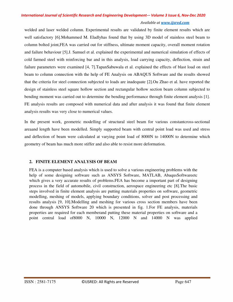
steps involved in finite element analysis are putting materials properties on software, geometric
modelling, meshing of models, applying boundary conditions, solver and post processing and
results analysis [9, 10].Modelling and meshing for various cross section members have been
done through ANSYS Software 20 which is presented in fig. 1.For FE analysis, materials
properties are required for each memberand putting these material properties on software and a
point central load of8000 N, 10000 N, 12000 N and 14000 N was applied
International Journal of Scientific Research and Engineering Development-– Volume 3 Issue 6, Nov-Dec 2020
Available at www.ijsred.com
ISSN : 2581-7175 ©IJSRED: All Rights are Reserved Page 648
Fig. 1. Meshing on models.
3. RESULTS AND DISCUSSION
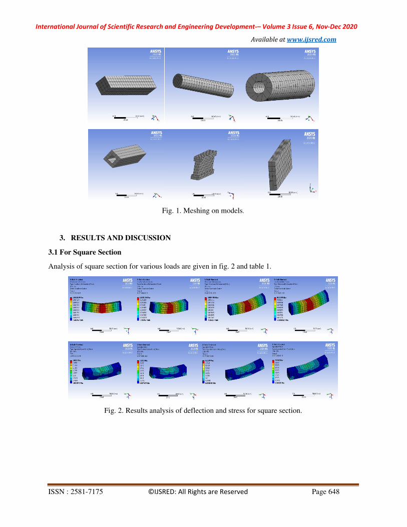
3.1 For Square Section
Analysis of square section for various loads are given in fig. 2 and table 1.
Fig. 2. Results analysis of deflection and stress for square section.
International Journal of Scientific Research and Engineering Development-– Volume 3 Issue 6, Nov-Dec 2020
Available at www.ijsred.com
ISSN : 2581-7175 ©IJSRED: All Rights are Reserved Page 649
Table1.Results of deflection and stress for square section at various loads.
S No Load (N) Deflection (mm) Stress (MPa)
1 8000 6.52 4.09
2 10000 8.14 5.12
3 12000 9.77 6.14
4 14000 11.40 7.16
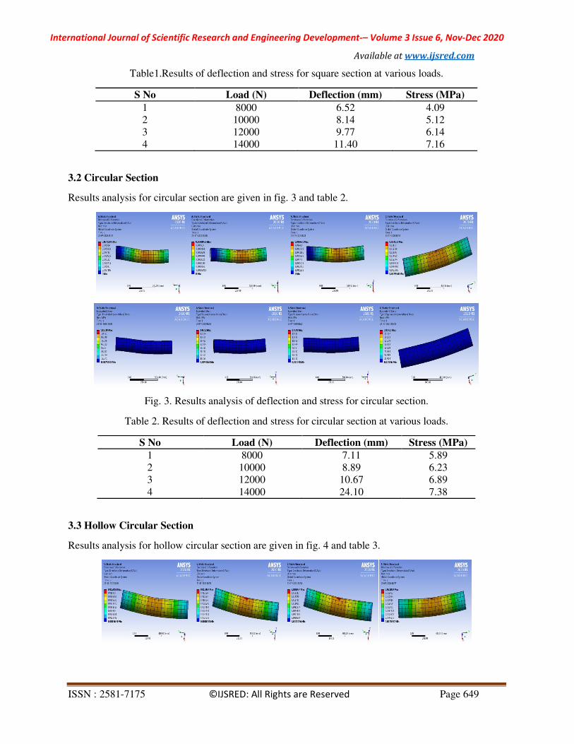
3.2 Circular Section
Results analysis for circular section are given in fig. 3 and table 2.
Fig. 3. Results analysis of deflection and stress for circular section.
Table 2. Results of deflection and stress for circular section at various loads.
S No Load (N) Deflection (mm) Stress (MPa)
1 8000 7.11 5.89
2 10000 8.89 6.23
3 12000 10.67 6.89
4 14000 24.10 7.38
3.3 Hollow Circular Section
Results analysis for hollow circular section are given in fig. 4 and table 3.
International Journal of Scientific Research and Engineering Development-– Volume 3 Issue 6, Nov-Dec 2020
Available at www.ijsred.com
ISSN : 2581-7175 ©IJSRED: All Rights are Reserved Page 650
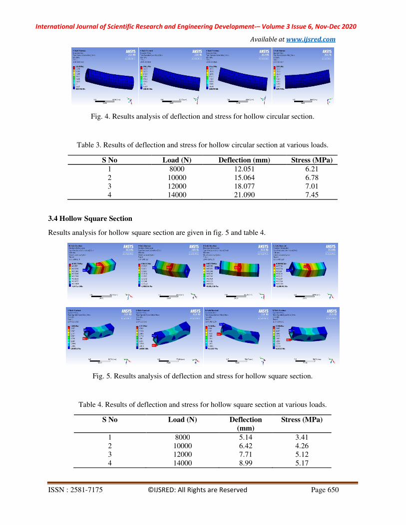
Fig. 4. Results analysis of deflection and stress for hollow circular section.
Table 3. Results of deflection and stress for hollow circular section at various loads.
S No Load (N) Deflection (mm) Stress (MPa)
1 8000 12.051 6.21
2 10000 15.064 6.78
3 12000 18.077 7.01
4 14000 21.090 7.45
3.4 Hollow Square Section
Results analysis for hollow square section are given in fig. 5 and table 4.
Fig. 5. Results analysis of deflection and stress for hollow square section.
Table 4. Results of deflection and stress for hollow square section at various loads.
S No Load (N) Deflection
(mm)
Stress (MPa)
1 8000 5.14 3.41
2 10000 6.42 4.26
3 12000 7.71 5.12
4 14000 8.99 5.17
International Journal of Scientific Research and Engineering Development-– Volume 3 Issue 6, Nov-Dec 2020
Available at www.ijsred.com
ISSN : 2581-7175 ©IJSRED: All Rights are Reserved Page 651
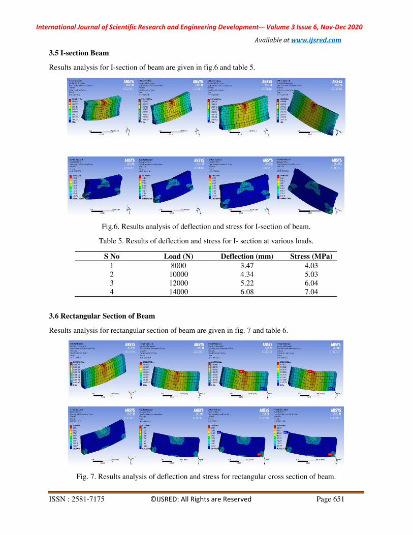
3.5 I-section Beam
Results analysis for I-section of beam are given in fig.6 and table 5.
Fig.6. Results analysis of deflection and stress for I-section of beam.
Table 5. Results of deflection and stress for I- section at various loads.
S No Load (N) Deflection (mm) Stress (MPa)
1 8000 3.47 4.03
2 10000 4.34 5.03
3 12000 5.22 6.04
4 14000 6.08 7.04
3.6 Rectangular Section of Beam
Results analysis for rectangular section of beam are given in fig. 7 and table 6.
Fig. 7. Results analysis of deflection and stress for rectangular cross section of beam.
International Journal of Scientific Research and Engineering Development-– Volume 3 Issue 6, Nov-Dec 2020
Available at www.ijsred.com
ISSN : 2581-7175 ©IJSRED: All Rights are Reserved Page 652
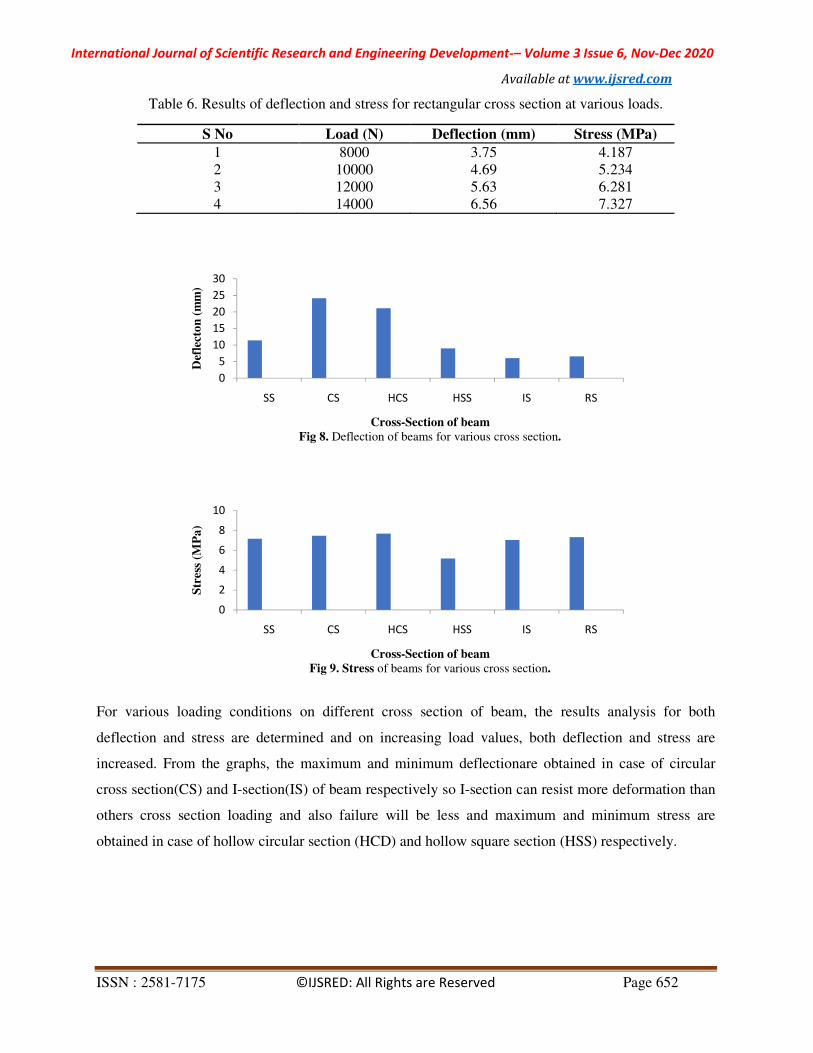
Table 6. Results of deflection and stress for rectangular cross section at various loads.
S No Load (N) Deflection (mm) Stress (MPa)
1 8000 3.75 4.187
2 10000 4.69 5.234
3 12000 5.63 6.281
4 14000 6.56 7.327
For various loading conditions on different cross section of beam, the results analysis for both
deflection and stress are determined and on increasing load values, both deflection and stress are
increased. From the graphs, the maximum and minimum deflectionare obtained in case of circular
cross section(CS) and I-section(IS) of beam respectively so I-section can resist more deformation than
others cross section loading and also failure will be less and maximum and minimum stress are
obtained in case of hollow circular section (HCD) and hollow square section (HSS) respectively.
0
5
10
15
20
25
30
SS CS HCS HSS IS RS
Def
lect
on
(m
m)
Cross-Section of beam
Fig 8. Deflection of beams for various cross section.
0
2
4
6
8
10
SS CS HCS HSS IS RS
Str
ess
(MP
a)
Cross-Section of beam
Fig 9. Stress of beams for various cross section.
International Journal of Scientific Research and Engineering Development-– Volume 3 Issue 6, Nov-Dec 2020
Available at www.ijsred.com
ISSN : 2581-7175 ©IJSRED: All Rights are Reserved Page 653
4. CONCLUSIONS
After analysing of different cross section of beam for various loading conditions, I-section can sustain
more load followed by rectangular section, hollow square section, square section, hollow circular
section and circular section. I-section of beam will be reliable to use and also can sustain more
deformation than others cross section of beam.
REFERENCES
[1] OuZhaoa, Leroy Gardner and Ben Young, Finite element modelling and design of stainless steel
SHS and RHS beam-columns under moment gradients, Thin-Walled Structures 134, 220–232, 2019.
[2] TapanSabuwala, Daniel Linzell and Theodor Krauthammer, Finite element analysis of steel beam
to column connectionssubjected to blast loads, International Journal of Impact Engineering 31, 861–
876, 2005.
[4] J. Samuel and P.S. Joanna, Experimental Study And Numerical Modelling On The Behaviour Of
Built-Up Cold-Formed Steel Beams With Diagonal Web Bars,
InternationalJournalofScientific&TechnologyResearchVolume 9, Issue 02, February 2020.
[5] Mohammed M. Eladly, Behaviour of stainless steel beam-to-column bolted connections Part 1:
Simplified FE model, Journal of Constructional Steel Research 164, 105784, 2020.
[6] Yidu Bu and Leroy Gardner, Laser-welded stainless steel I-section beam-columns: Testing,
simulation and design, Engineering Structures 179, 23–36, 2019.
[7] Yidu Bu and Leroy Gardner, Finite element modelling and design of welded stainless steel
I-section columns, Journal of Constructional Steel Research,
https://doi.org/10.1016/j.jcsr.2018.03.026.
[8] S. Arun Kumar, V. Velmurugan, V. Paramasivam and S. Thanikaikarasan, Modelling analysis of
stainless steel cantilever beam crack dynamics using finite element method, Materials Today:
Proceedings, https://doi.org/10.1016/j.matpr.2019.06.740.
[9] SanasamVipej Devi and KonjengbamDarunkumar Singh, Finite element study of the stiffening
effects on torsional capacity of perforated stainless steel slender semi-elliptical hollow section
members, Structures 26, 66–78, 2020.
[10] Yue Li and YaqiangLi, Evaluation of elastic properties of fiber reinforced concrete

International Journal of Scientific Research and Engineering Development-– Volume 3 Issue 6, Nov-Dec 2020
Available at www.ijsred.com
ISSN : 2581-7175 ©IJSRED: All Rights are Reserved Page 654
with homogenization theory and finite element simulation, Construction and Building Materials 200,
301–309, 2019.
[11] YuQUAN and ChangchunPEI, Finite element analysis of flexural behavior of different fiber
reinforced ultra-high-strength concrete beam under different environments, 5th International
Conference on Machinery, Materials and Computing Technology (ICMMCT) 2017.