Embed Size (px)
Citation preview
SECTION 5.28.30 - FIRE ALARM AND SIGNALING DESIGN AND CONSTRUCTION STANDARD
Design & Construction Standards, Revised January 2013 5.28.30-1
PART 1 GENERAL
1.01 Scope of Standard
A. This Standard is intended to assure that fire alarm and signaling systems at The
University of Texas at Austin provide the highest level of fire safety possible. This
document is not intended to be a guide specification. 1.02 Scope of Work
A. This standard is to be used in the development of all fire alarm and signaling
system designs for buildings and structures at The University of Texas at Austin.
B. This standard is to apply to all fire alarm and signaling system components and
equipment installed at any University of Texas at Austin campus during new
construction or as part of any improvement project.
C. The work addressed in this section consists of a fire protection system, which may
include, and at least will be coordinated with all of the following building systems
or components:
1. Fire Suppression Systems.
2. HVAC, fire, smoke, and combination fire/smoke dampers.
3. Emergency power systems.
4. Elevator installation. See the Texas State Elevator Code ASME/ANSI
A17.1 and ASME/ANSI A17.3.
5. Central Control and Monitoring System.
6. Security Systems.
7. Gas Detection Systems (future)
8. Mass Notification Systems (future)
9. Smoke Control Systems (future)
D. Referenced Publications: The documents or portions thereof listed in this section
shall be considered part of the requirements of this document. (Utilize latest
editions)
1. NFPA 1, Uniform Fire Code 2. NFPA 13, Standard for the Installation of Sprinkler Systems
3. NFPA 14, Standard for the Installation of Standpipe and Hose Systems 4. NFPA 17, Standard for Dry Chemical Extinguishing Systems 5. NFPA 17A, Standard for Wet Chemical Extinguishing Systems
6. NFPA 20, Standard for the Installation of Stationary Pumps for Fire
Protection 7. NFPA 70, National Electrical Code 8. NFPA 72, National Fire Alarm and Signaling Code
9. NFPA 90A, Standard for the Installation of Air Conditioning and Ventilating Systems
10. NFPA 92, Standard for Smoke-Control Systems
11. NFPA 101, Life Safety Code 12. NFPA 2001, Standard on Clean Agent Fire Extinguishing Systems

SECTION 5.28.30 - FIRE ALARM AND SIGNALING DESIGN AND CONSTRUCTION STANDARD
Design & Construction Standards, Revised January 2013 5.28.30-2
13. NFPA 5000, Building Construction and Safety Code
14. IBC-International Building Code
15. IFC-International Fire Code 16. UL Standard 268, Smoke Detectors for Fire Protective Signaling Systems 17. UL Standard 268A, Smoke Detectors for Duct Application 18. UL Standard 346, Waterflow Indicators for Fire Protective Signaling
Systems
19. UL Standard 521, Heat Detectors for Fire Protective Signaling Systems 20. UL Standard 864, Control Units for Fire Protective Signaling Systems 21. UL Standard 1424, Cables for Power—Limited Fire Protective Signaling
Systems 22. UL Standard 1480, Speakers for Fire Protective Signaling Systems
23. UL Standard 1481, Power Supplies for Fire Protective Signaling Systems 24. UL Standard 1711, Amplifiers for Fire Protective Signaling Systems
25. UL Standard 1971, Signaling Devices for the Hearing Impaired 26. UL Standard 2572, Control and Communication Units for Mass Notification
Systems 27. ADA-Americans with Disabilities Act
28. TAS-Texas Accessibility Standards
29. American Society of Mechanical Engineers (ASME)/American National
Standards Institute (ANSI):
a. ANSI A17.1, Elevator Code, latest edition.
b. ANSI A17.3, Elevator Code for Existing Elevators, latest edition.
c. ANSI A117.1, Accessibility Code, latest edition.
1.03 Objectives
A. This standard is intended to achieve consistently high levels of fire
detection/alarm system performance by:
1. Allowing designers to incorporate required or desired features as early in
the design development process as possible.
2. Assuring all systems are designed to meet all applicable codes, ordinances,
laws, and sound engineering judgment.
3. Providing a basis for a general understanding among all parties involved
in the design of systems. 1.04 Concepts
A. All systems are to be compliant with applicable paragraphs of NFPA 101 "Life
Safety Code".
B. All systems are to be compliant with the requirements of NFPA 72 "National Fire
Alarm and Signaling Code".
1.05 System Features
A. All system product lines shall be comprised of components capable of
SECTION 5.28.30 - FIRE ALARM AND SIGNALING DESIGN AND CONSTRUCTION STANDARD
Design & Construction Standards, Revised January 2013 5.28.30-3
providing the following features when appropriate and specified by the project
documents or the University:
1. Floor above/floor below notification.
2. Private alarm notification.
3. Positive alarm sequence.
4. Voice alarm notification.
5. Fireman's communications.
6. Elevator capture/recall.
7. Elevator power shunt trip.
8. Smoke control/fan shutdown.
9. Door release.
10. Release locks on normally locked egress doors.
11. Release and monitoring of clean agent and/or pre-action sprinkler systems.
12. Alarm Verification.
13. Monitor non-water based fire suppression systems.
14. Multiple channel digital voice.
15. Provisions for Mass Notification signals (future).
B. Provide audible notification throughout the building in accordance with NFPA
72. Provide an individually silenceable 10 inch, 24 VDC general alarm bell on
the building exterior.
C. Visual notification to ADA levels and TAS requirements shall be provided
throughout the building.
D. Smoke detectors shall be provided at all elevator lobbies, elevator
equipment rooms and elevator hoistways to perform capture/recall functions.
E. All systems shall be designed to provide manual means of alarm initiation at
every exit from every level. Elevators are not to be considered an exit or
means of egress.
1.06 Description of Work
A. All designs shall provide for each building a complete and working digital,
addressable, closed circuit, automatic and manual fire detection / alarm and
signaling system for each floor of the building to perform detection, monitoring,
signaling and other alarm and control functions for the building. 1.07 Fire Alarm and Signaling System Engineering Documents and Bid Design Documents
A. Approval and Acceptance
1. The Authority Having Jurisdiction (AHJ) shall be notified prior to
installation or alteration of equipment or wiring.
2. At the AHJ‘s request, complete information regarding the system or system
alterations, shall be submitted for approval.
3. Neither approval nor acceptance by the AHJ shall relieve the designer(s) or
installer(s) from providing a system compliant with all governing laws,
SECTION 5.28.30 - FIRE ALARM AND SIGNALING DESIGN AND CONSTRUCTION STANDARD
Design & Construction Standards, Revised January 2013 5.28.30-4
codes or standards.
4. Deviations from requirements of governing laws, codes or standards, shall
be clearly identified and documented as such. Documentation of
equivalencies shall be provided in accordance with NFPA 72, Section 1.5.
B. Design Documents
1. Prior to installing new systems, replacing an existing system, or upgrading a
system, preliminary design documents shall be prepared.
2. Systems that are altered shall have design documents prepared that are
applicable to the portion(s) of the system being altered.
3. Preliminary design documents shall contain but not limited to the following
information related to the system.
a. Specifications applicable to the project.
b. Floor plan scale shall be not smaller than 1/8‖ = 1‘ and shall include
a bar scale on the respective sheets.
c. Floor plans shall have building column lines shown and identified.
d. Fire safety and related symbols shown on drawings and diagrams
shall comply with NFPA 170.
e. When devices are shown on preliminary drawings, the devices shall
be located in accordance with standards, listings, and limitations of
the equipment specified. When no particular product limitations are
specified, the prescriptive criteria of applicable standards shall be
used.
f. Interface between systems such as fire alarm, mass notification,
security, HVAC, smoke control, elevators, access control, other fire
protection systems, etc.
g. Input/Output matrix showing sequence of operation between
actions.
h. Survivability of system circuits and equipment.
i. Input Devices
i. Automatic smoke detection shall be provided at the location
of each fire alarm control unit(s), notification appliance
circuit power extenders, and supervising station transmitting
equipment to provide notification of fire at that location.
1. Where ambient conditions prohibit installation of
automatic smoke detection, automatic heat detection
shall be permitted.
ii. Manual fire alarm pull stations shall be provided each
required exit from every level.
1. All manual pull stations located in buildings that are
used for classes shall have an STI Stopper II or equal.
iii. The location of detectors used to monitor HVAC systems,
close dampers and/or control smoke management systems
shall be the sole responsibility of the fire alarm system
engineer, and/or preliminary design professional. The
engineer, and/or preliminary design professional of fire alarm
system shall coordinate with the mechanical engineer to
SECTION 5.28.30 - FIRE ALARM AND SIGNALING DESIGN AND CONSTRUCTION STANDARD
Design & Construction Standards, Revised January 2013 5.28.30-5
properly locate detectors used to monitor HVAC systems,
close dampers and/or control smoke management systems.
j. Audible Notification
i. The ambient sound pressure levels used as a basis for the
system design shall be shown on plans.
ii. Acoustically Distinguishable Spaces (ADS) assignments shall
be submitted for review and approval.
iii. Each ADS shall be identified as requiring or not requiring
voice intelligibility.
iv. ADS measurement points shall be shown on plans or
otherwise described in a way that permits future testing at the
same locations.
v. Audible notification devices shall have the dB output for each
speaker labeled adjacent to the speaker to substantiate the
design and assist the installer in sizing amplifiers.
vi. Acoustic properties of spaces and sound loss shall be
considered and documented on design drawings with respect
to speaker selection and placement to ensure audibility and
intelligibility requirements can be met. Acoustical treatments
shall include, but not be limited to sound baffles, sound
absorption materials, or other such physical treatments to a
space.
vii. Achieving intelligibility in certain spaces such as large open
or hard surfaced spaces often requires evaluation of the
environmental acoustic properties. The burden of audibility
and speech intelligibility is frequently placed on the installing
fire alarm contractor. However, the contractor has no control
over the architectural acoustic aspects of spaces. Therefore, it
is essential that the architects and engineers account for the
necessary acoustic treatments and intended speaker placement
during the physical design of the space.
viii. The architect, engineer, and/or preliminary design
professional shall identify the need for, and provide
provisions for acoustical treatments required to achieve
speech intelligibility.
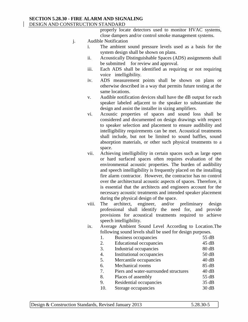
ix. Average Ambient Sound Level According to Location.The
following sound levels shall be used for design purposes.
1. Business occupancies 55 dB
2. Educational occupancies 45 dB
3. Industrial occupancies 80 dB
4. Institutional occupancies 50 dB
5. Mercantile occupancies 40 dB
6. Mechanical rooms 85 dB
7. Piers and water-surrounded structures 40 dB
8. Places of assembly 55 dB
9. Residential occupancies 35 dB
10. Storage occupancies 30 dB
SECTION 5.28.30 - FIRE ALARM AND SIGNALING DESIGN AND CONSTRUCTION STANDARD
Design & Construction Standards, Revised January 2013 5.28.30-6
x. In existing facilities the typical average ambient sound levels
specified above shall not be used in lieu of actual sound level
measurements.
1. The authority having jurisdiction shall be permitted
to require actual sound level measurements be taken
by an approved independent third party with
expertise in audio engineering.
2. The independent third party shall be independent of
the Professional Service Provider or design team.
3. All actual sound level measurements shall be
performed prior to system design.
k. All control devices utilized for controlling auxiliary functions shall
be mounted within 3 feet of the equipment being controlled.
4. Preliminary design documents for smoke managements systems shall
contain information related to the system which shall include preliminary
plans such as those used for bidding or solicitation, specifications,
input/output matrix, input device locations, fire department smoke control
panel locations, control function locations and graphic panel locations.
C. All designs shall be performed by State of Texas Fire Alarm Planning
Superintendent (NICET Level III in Fire Alarm Systems) or by a Professional
Engineer (P.E.) registered in Fire Protection in the State of Texas.
1.08 Quality Assurance
A. Fire Alarm Contractor Qualifications:
1. Authorized and designated representative of fire alarm manufacturer to
sell, install, and service proposed manufacturer's equipment. The
contractor shall have a minimum of 2 factory trained and certified
technicians for the system proposed.
2. Licensed by the Texas State Fire Marshal‘s Office to sell, install, and
service fire alarm systems.
3. Actively engaged in business of selling, installing, and servicing fire alarm
systems for at least five years with minimum of ten such installations
completed and operating properly.
4. Equipment furnished shall be of current manufacture.
B. Fire Alarm and Signaling System Shop Drawing Designer and System
Programmer Qualifications
1. Personnel who are factory trained and certified for fire alarm system
design and emergency communications system design and programming
of the specific type and brand of system and who are acceptable to the
University of Texas Fire Marshal‘s Office.
2. The design shall be performed by State of Texas Fire Alarm Planning
Superintendent (NICET III) or by a Professional Engineer (P.E.)
registered in Fire Protection in the State of Texas.
3. The programming shall be performed by individuals complying with
one of the following qualifications:

SECTION 5.28.30 - FIRE ALARM AND SIGNALING DESIGN AND CONSTRUCTION STANDARD
Design & Construction Standards, Revised January 2013 5.28.30-7
a. State of Texas Fire Alarm Planning Superintendent (NICET III).
b. NICET Level II and factory trained and certified for programming
of the specific type and brand of system.
c. Personnel who are factory trained and certified for programming
of the specific type and brand of system and who are acceptable to
the University of Texas Fire Marshal‘s Office and the Fire Safety
Systems Shop.
4. The system designer and programmer shall provide evidence of their
qualifications and/or certifications to the University of Texas Fire
Marshal‘s Office.
5. Shop drawings shall be revised as necessary following installation to
represent as-built conditions and include record drawings on all new
systems and any system modifications.
C. System Installer
1. Fire alarm systems and emergency communications systems installation
personnel shall be qualified or shall be supervised by persons who are
qualified in the installation, inspection, and testing of the systems.
2. The installation of all fire alarm devices, signaling devices or systems,
including monitoring equipment shall be performed by or under the
direct supervision of a licensed fire alarm technician or a fire alarm
planning superintendent. The certifying licensee shall be licensed under
the ACR number of the primary registered firm and shall be present for
the final acceptance test prior to certification.
3. The system installer shall provide evidence of their qualifications and/or
certifications to the University of Texas Fire Marshal‘s Office.
D. The equipment furnished shall be listed and approved by a testing laboratory that have been approved by the State of Texas Commission on Fire Protection. This listing shall be for all functions required by this specification.
E. The Contractor shall provide a signed "Fire Alarm and Emergency
Communication System Inspection and Testing Form‖ for each system,
consisting of completed copies of the appropriate pages from NFPA 72, at the
final Acceptance Test. The fire alarm contractor shall attach the appropriate
fire alarm tags to the panel as required by the State of Texas.
F. The fire alarm contractor shall provide the Texas Insurance Code Fire Alarm
System Installation Inspection Form to the University of Texas Fire Marshal‘s
Office at the following intervals:
1. At the completion of the device back-box installation but prior to the start
of cable installation;
2. At the completion of cable installation but prior to the start of device
installation; and
3. At the completion of device installation but prior to activating the fire
alarm system.
G. Provide staff installation superintendents who are licensed by the State Fire

SECTION 5.28.30 - FIRE ALARM AND SIGNALING DESIGN AND CONSTRUCTION STANDARD
Design & Construction Standards, Revised January 2013 5.28.30-8
Marshal‘s Office for such purpose and under whose supervision installation,
final connections, and testing will be performed.
H. All systems shall comply with applicable paragraphs of the National Electric
Code. 1.09 Submittals
A. Prior to installation, the following documents shall be provided to the
University of Texas at Austin for reference and/or approval:
1. Shop Drawings: Include manufacturer's name, model numbers, ratings,
power requirements, equipment layout, conduit, device arrangement,
and complete point to point wiring diagrams along with other required
information including but not limited to:
a) General Drawing Notes
b) Electrical back box requirements
c) Control Equipment Schedules
d) Panel Schematics showing all connections, between modules within
panels, to all modules from field wiring with zones identified.
e) Riser Diagrams indicating circuits, type of devices, number of
devices, number of conductors, conduit size, junction boxes, and
zones.
f) Scaled floor plans with layout of all devices with point numbers for
initiating and notification devices, wiring connections, zoning, wire
sizes and routing.
I. Wattage setting for each speaker labeled adjacent to the
speaker. Candela rating for each strobe labeled adjacent to
the strobe.
II. All new devices, existing devices and devices to be
removed shall be shown. 2. Detailed Legend
3. Detailed input/output matrix.
B. Product Data: Provide electrical characteristics, connection requirements and
compatibility listing showing that components are compatible with each other
including but not limited to:
1. Full equipment list including model numbers and quantities
2. Complete system operation
3. Highlighted Data Sheets on Devices and Products
a. Fire Alarm Control Panel
b. Wiring
c. Batteries
d. Detectors
e. Manual Stations
f. Audible Signaling Devices
g. Visual Signaling Devices
h. Control Devices
4. Wiring diagrams of all equipment
SECTION 5.28.30 - FIRE ALARM AND SIGNALING DESIGN AND CONSTRUCTION STANDARD
Design & Construction Standards, Revised January 2013 5.28.30-9
5. Installation instructions for all equipment
6. Equipment testing procedures
7. Equipment maintenance manuals
8. Wire data sheets.
C. System Calculations - Complete calculations shall be provided which show
the electrical load on the following system components (identify all
mathematical formulas, variables, and constants used in all calculations):
1. Each system power supply, including stand alone booster supplies
2. Standby Battery Calculations plus a 20 percent de-rating factor
3. Voltage drop calculations for each type of circuit
4. dB loss calculations for speaker circuits
5. Speaker circuit loading and amplifier loading
6. Strobe circuit loading
7. Each auxiliary control circuit that draws power from any system power
supply
8. 120VAC power requirement calculations
D. Software and Database Information:
1. Proposed point numbers.
2. Labels of all addressable devices.
3. English action messages.
4. Add Programming rules, Equations, with comments listed.
5. Please send a copy to FSS and PMCS‘ Project Support Fire Protection
Engineer.
E. The submittal package shall be signed by the State of Texas Fi re Alarm
Planning Superintendent (NICET III) or signed and sealed by a Professional
Engineer (P.E.) registered in Fire Protection in the State of Texas.
1. All code deficiencies and/or variances shall be noted on the fire alarm
submittals and/or drawings.
1.10 Technical Assistance
A. The authority having jurisdiction shall be permitted to require a review by an
approved independent third party with expertise in the matter to be reviewed at
the submitter‘s expense.
B. The independent reviewer shall provide an evaluation and recommend
necessary changes of the proposed design, operation, process, or new
technology to the authority having jurisdiction.
PART 2 PRODUCTS
2.01 Fire Alarm Control Units (FACU)
SECTION 5.28.30 - FIRE ALARM AND SIGNALING DESIGN AND CONSTRUCTION STANDARD
Design & Construction Standards, Revised January 2013 5.28.30-10
A. Acceptable Manufacturers models EST-3, Notifier 3030, Siemens XLSV FIRE
FINDER, and Simplex 4100U.
1. All Fire Alarm System components shall be keyed alike.
B. All fire alarm control units shall be intelligent, addressable Central Processing
Units (CPU) based and meets the latest edition of UL 864.
C. All FACUs shall be capable of providing circuit integrity monitoring for all
Signaling Line Circuits at a level of Class A, as defined in NFPA 72.
D. All FACUs shall be capable of providing circuit integrity monitoring of
Initiating Device Circuits (IDC's) at a level of Class B as defined in NFPA 72.
E. All FACUs shall be capable of providing circuit integrity monitoring of
Notification Appliance Circuits (NAC's) at a level of Class B as defined in
NFPA 72.
F. Panels shall have provisions for smoke detector "Alarm Verification" for
Signaling Line Circuits shall be provided.
G. Manufactured terminal boxes labeled ―FIRE ALARM TERMINAL BOX‖
Space Age TC2 series or equal.
H. With each installed field device affix a label to indicate the devices full address
on its signaling line circuit.
I. Mark each cable or wire to designated terminal with labeling tool.
J. All FACUs shall provide twenty percent (20%) excess power supply, input
circuit, and output circuit capacity at final acceptance to allow for future
expansion by the owner.
K. Zone labeling shall be textual by alpha-numeric display at the FACU and
remote annunciator to allow ―first response‖ by persons not trained in fire
alarm technology.
L. Textual (alpha-numeric) language shall be conventional, concise, clear and
accurate to facilitate rapid response. The label shall contain the device type,
floor location, equipment or area served, and an exact device location,
M. All FACUs shall provide a control to bypass the Public Alarm to allow
for maintenance and testing, and to reduce disruption.
N. All FACUs shall provide controls to override door holder release, smoke
control activation, damper activation, and fan shutdown features to allow for
maintenance and testing. Program panel to allow functions to be disabled by
floor or by group as required by UT. A means to disable all water flows shall be
provided.

SECTION 5.28.30 - FIRE ALARM AND SIGNALING DESIGN AND CONSTRUCTION STANDARD
Design & Construction Standards, Revised January 2013 5.28.30-11
O. All FACUs shal l be connected to a Primary and Secondary Power source.
The secondary power supply shall be sized to provide 5 minutes of operation
in alarm conditions after 24 hours of system operation in standby power.
Where voice evacuation systems are utilized, 15 minutes of alarm shall be
provided.
P. All FACUs shall provide a separate digital address for each initiating device
to facilitate rapid response and maintenance and testing.
Q. All FACUs shall provide a separate digital address for each individual flow
switch.
R. All programming shall be permanent and non-volatile to reduce outage time
due to failure.
S. All FACUs shall provide a panel mounted printer to print a log of all
status change activity.
T. All FACUs shall be listed and approved as the smoke detector sensitivity test
set to reduce maintenance costs.
U. All FACUs shall be capable of providing drift compensation. Drift
compensation is considered equal to adjustability at the detector.
V. All FACUs shall be field programmable, using internal or connected
components, for all changes, alterations, modifications, additions, deletions
and hardware and software upgrades.
W. All messages shall be recorded in a female voice.
X. All FACUs sha l l be capable, using internal or connected components, of
generating comprehensive reports for sensitivity, verification counts, address
registers.
Y. Where a clean agent fire suppression system and/or preaction sprinkler system
is specified for the project, the FACU shall be UL listed for releasing service
the preaction and/or clean agent system specified in Section 5.21.20.
Initiating devices shall be connected to a UL listed releasing panel. All
initiating, output and releasing circuits shall reside in one fire alarm control
panel.
Z. A fault isolation device shall be provided electrically between each building
level. This device shall be capable of automatically isolating wire-to-wire
faults on each SLC to the building level involved. The device shall be
powered by the SLC loop. The device shall provide visual indication at the
device of a short circuit (isolate) condition. The device shall reset to the
normal mode upon elimination of the wire-to-wire short. All fault isolation
devices shall be physically located within the marshaling box for that floor.

SECTION 5.28.30 - FIRE ALARM AND SIGNALING DESIGN AND CONSTRUCTION STANDARD
Design & Construction Standards, Revised January 2013 5.28.30-12
2.02 Remote Monitor
A. All systems shall be capable of interconnection to the Campus-Wide
Proprietary Supervisory Signaling System utilizing one set of Form C contacts
(one normally open, one normally closed) for transmission of each of the
following signals separately:
1. ALARM
2. WATERFLOW
3. SUPERVISORY
4. TROUBLE
B. All systems shall provide a Wiring Interface Panel (Space Age TC2 or equivalent) to accommodate the connection between the new fire alarm system and the existing Proprietary Protective Signaling System. The WIP shall be accessible and located within a room that is nearest to the campus utilities tunnel system. Conduit and 18/10 conductor cabling shall be provided between this panel and the FACU to perform the functions listed above. The contractor will be responsible for extending any existing campus monitoring wires when needed to accommodate a new WIP box location.
2.03 Distributed Power Supplies
A. Distributed power supplies for powering Notification Appliance Circuits,
beam smoke detectors, and control relays may be used.
B. All distributed power supply inputs shall be controlled by addressable
interface devices located on the same floor levels as the power supply and
controlled by the SLC serving the area to facilitate maintenance.
C. The distributed power supplies shall be sized to provide 5 minutes of operation
in alarm after 24 hours of system operation in standby power. Where voice
evacuation systems are utilized, 15 minutes of alarm shall be provided after
operation in standby power.
1. The power supplies shall be sized to provide 20 percent spare capacity to
accommodate future expansion.
D. The power supplies shall be located in an area that is readily accessible to the
fire safety shop and mounted at a height that is easily accessible for regular
routine maintenance.
E. All remote power supplies shall be of the same manufacturer as the fire alarm
system. All remote power supplies shall also be keyed the same as the fire
alarm system.

SECTION 5.28.30 - FIRE ALARM AND SIGNALING DESIGN AND CONSTRUCTION STANDARD
Design & Construction Standards, Revised January 2013 5.28.30-13
2.04 Manual Pull Stations
A. All manual pull stations shall be of the "double-action" type to reduce
unintentional or vandal alarms. Pull stations required to break glass to activate
are not acceptable. Provide pull stations that utilize the same key as FACU
for resetting.
B. Each manual pull station shall have a unique digital address on the SLC.
C. Where separate addressable monitor modules are used for monitoring
conventional type manual pull stations, the modules are required to be installed
within the manual pull station back box.
D. All manual pull stations located in buildings that are used for classes shall have
an STI Stopper II or equal.
1. All Stopper II‘s shall be 24 VDC powered.
2. The power shall be received from an auxiliary power supply of the same
model as those supplied to power the building visual notification.
3. The auxiliary power supply shall be monitored for trouble by the FACU.
4. The 24 VDC power to the Stopper II‘s shall not be supervised.
5. The quantity and location of the auxiliary power supplies shall be
determined by the engineer or contractor.
6. A smoke detector located at the auxiliary power supply that supplies power
to the Stopper II‘s is not required.
7. The individual Stopper II‘s shall not be monitored by the FACU.
8. Manual pull stations that are protected by Stopper II‘s shall be single
action. 2.05 Heat Detectors
A. All heat detectors shall be fixed temperature, rate-of-rise, or combination
fixed temperature and rate-of-rise, spot type.
B. Each addressable or conventional heat detector shall have a unique address on
the SLC.
C. Non resetting detectors shall give visual indication of "ALARM" condition
to facilitate rapid response.
D. Where separate addressable monitor modules are used for monitoring
conventional type heat detectors, the modules are required to be installed within
the heat detector junction box.
2.06 Smoke Detectors
A. All spot type smoke detectors shall be photoelectric or combination
photoelectric and ionization type.
SECTION 5.28.30 - FIRE ALARM AND SIGNALING DESIGN AND CONSTRUCTION STANDARD
Design & Construction Standards, Revised January 2013 5.28.30-14
B. Each smoke detector, whether spot-type, or projected-beam type, shall have
a unique digital address on the SLC.
C. All smoke detectors shall be measurable and adjustable for sensitivity.
D. All smoke detectors, except projected beam type, shall be powered from the
SLC.
E. The FACU shall function as the smoke detector sensitivity test set and shall
be approved and listed for that service.
F. All smoke detectors shall meet or exceed the requirements of Underwriter's
Laboratory Standard 268, as amended, and shall be listed and approved for use
with the FACU provided.
2.07 Duct-Mounted Smoke Detectors
A. It is the joint responsibility of the Fire Alarm and the Mechanical Contractors
to assure that all supply and return air is sampled as required per NFPA
90A. Label duct work and direction of air flow and identify the proper
locations for duct detectors. Provide only addressable system duct detectors,
factory installed duct detectors within the air handling unit are not acceptable.
B. ¾ inch armorflex or equal type insulation shall be installed behind all cold deck
mounted duct detectors. The insulation shall be sized so that it is a minimum of
3 inches wider than the detector in all directions to allow for sealing the
armorflex to the existing insulation
C. The fire alarm planner/designer shall affix a label at the locations on duct work
intended for smoke monitoring in coordination with the mechanical engineer.
The label will identify the AHU number, identify if the duct is for supply or
return air, and the direction of the airflow in the duct.
2.08 Projected-Beam Smoke Detectors
A. All projected-beam detectors shall operate on the infrared principle.
B. All projected-beam detectors shall have automatic gain control circuits to
compensate for deterioration of signal strength due to environmental factors
such as dirt and dust accumulation, component aging and temperature
fluctuations.
C. Transmitting and receiving units of projected-beam detectors shall be
protected from physical damage.
D. All projected-beam smoke detectors shall have circuits to prevent "false"
alarms due to sudden and complete obscuration.

SECTION 5.28.30 - FIRE ALARM AND SIGNALING DESIGN AND CONSTRUCTION STANDARD
Design & Construction Standards, Revised January 2013 5.28.30-15
E. Written AHJ approval will be required for the installation of beam smoke
detectors.
2.09 Air Sampling Smoke Detection
A. Provide air sampling smoke detection system if required by the project.
B. Locate air sampling ports in accordance with NFPA 72 and manufacturer‘s
requirements.
C. Maintain a maximum transport time of 120 seconds, or the transport time specified by the manufacturer, from the farthest sampling point, whichever is less.
D. Utilize CPVC piping that is listed for use in air sampling systems. Label
piping as required per NFPA 72.
E. Air sampling system power supplies shall be monitored for any impairment
and shall all be keyed alike to FACU. The power supplies shall be of the same
manufacturer as the sampling system unless otherwise specified in the
manufacturer‘s documentation.
F. Any impairment of the air sampling system shall report to the building fire
alarm system.
2.10 Waterflow Switches
A. Fire detection/signaling systems shall be interconnected to the fire sprinkler
systems. Waterflow switches shal l be set for a 60 second or greater
delay/retard not to exceed 90 seconds prior to the "ALARM".
B. Each waterflow switch shall be monitored w i t h a unique digital address on
the SLC.
C. It is the responsibility of the Sprinkler Contractor to locate the waterflow
switches to assure indication of water flow within the building and at each
level of the building to reduce water damage.
2.11 Supervisory (Tamper) Switches
A. Connect tamper switches installed on all sprinkler or standpipe system valves
to the fire alarm system to indicate closing or opening of the valves.
B. Each tamper switch shall be monitored with a unique digital address on the
SLC.

SECTION 5.28.30 - FIRE ALARM AND SIGNALING DESIGN AND CONSTRUCTION STANDARD
Design & Construction Standards, Revised January 2013 5.28.30-16
2.12 Audible Appliances
A. Fire alarm system audible notification is required to be provided by speakers
in all buildings. The fire alarm s i g n a l generated shall be the distinctive
three-pulse temporal pattern described by NFPA 72 and ANSI codes.
B. The Evacuation Signal produced by the speakers shall be alternated with a
custom textual message as indicated in Section 3.07 below.
C. Provide audible systems with voice intelligibility measured in accordance with
the guidelines in Annex A of IEC 60849, Sound Systems for Emergency
Purposes. When tested in accordance with Annex B, Clause B1, of IEC 60849,
the system shall considered acceptable if at least 90 percent of the measurement
locations within each area have a measured STI of not less than 0.45 (0.65 CIS)
and an average STI of not less than 0.50 STI (0.70 CIS).
2.13 Visual Appliances
A. All visual notification appliances shall be xenon strobe, compliant with
current requirements of ADA and TAS.
B. All visual notification devices within a room or adjacent space within the field
of view shall be synchronized as required per NFPA 72.
C. Strobes shall be clear or nominal while meeting the listing requirements of
UL 1971 and either have no marking or be marked with the word ―ALERT‖
stamped or imprinted on the appliance and be visible to the public.
2.14 Remote Annunciator
A. When required by the project, an LCD remote annunciator shall be located in
an open accessible area at or adjacent to the main ground level entrance to
the building. The FACU may then be located in a remote location or room.
B. Remote annunciator must display the same addressable and common signal
information as the main FACU.
2.15 Monitoring Devices
A. Addressable monitoring devices used to monitor contact-closure initiating
devices such as waterflow switches, and tamper switches shall derive power
from the SLC to which they are connected.
B. Each monitoring device shall have a unique digital address on the SLC.
SECTION 5.28.30 - FIRE ALARM AND SIGNALING DESIGN AND CONSTRUCTION STANDARD
Design & Construction Standards, Revised January 2013 5.28.30-17
2.16 Control Devices
A. Addressable control devices shall not control more than one type of
appliance/device.
B. SLC form ‗C‖ Relay shall be rated for the load. Interposing relays are not
allowed. 2.17 Documentation Storage
A. Storage cabinet shall be provided at or adjacent to (within five feet of) the
FACU. This cabinet shall be a Space Age DBXA or equal 64 and capable
of storing and securing all documents required for system maintenance and
response. Storage shall be s e p a r a t e d from all active electrical, electronic, or
electromechanical parts and components. If adequate, storage may contain
unconnected spare/repair parts.
2.18 Remote Microphone
A. Remote microphones shall be installed at all new and existing FACU‘s with
voice capabilities on the campus of the University of Texas at Austin as an
ancillary function. The remote microphone shall be installed within five feet of
the Fire Alarm Control Units or within five feet of the Fire Command Center
outside of any locked rooms. The remote microphone shall provide Building
Managers with a simple means to activate ―All EVACS SPEAKERS‖. Visual
notification shall not activate upon the activation of the remote microphone.
Any fire alarm signal shall take precedence over the remote microphone use
and the remote microphone shall be rendered inoperable. The remote
microphone shall have a lower priority and shall not interfere with the
performance requirements of the fire alarm system or mass notification system.
The Remote Microphone shall be in a locked enclosure (key to be specified).
B. Remote Microphone shall consist of the following features:
1. A supervised keyed microphone handset.
2. Surface mounted lockable cabinet.
3. Lock shall be keyed differently than the Fire Alarm Control Unit
(FACU).
4. Power On LED.
5. Trouble LED.
6. Ready or Active LED indicators
PART 3 INTERCONNECTION AND OPERATION

SECTION 5.28.30 - FIRE ALARM AND SIGNALING DESIGN AND CONSTRUCTION STANDARD
Design & Construction Standards, Revised January 2013 5.28.30-18
3.01 Signaling Line Circuits (SLC)
A. All FACUs shall provide circuit integrity monitoring for all Signaling Line
Circuits at a level of Class A serving no more than 3 levels with short isolators
in place for each level.
B. All the following devices/appliances shall be individually addressed on the
SLC:
1. Smoke detectors.
2. Heat detectors.
3. Manual stations.
4. Monitor devices.
5. Control devices.
6. IDCs.
7. Audio NACs.
8. Visual NACs. 3.02 Initiating Device Circuits (IDC)
A. Initiating Device Circuits (IDCs) shall be monitored at a level of Class B.
3.03 Notification Appliance Circuits (NAC)
A. All Notification Appliance Circuits (NACs) shall be monitored at a level of
Class B.
B. Direct current notification appliance power provided from a distributed
power supply shall be controlled by a digital addressable control device on the
SLC.
3.04 Auxiliary Functions
A. Locate control devices utilized for operating auxiliary functions mounted
within 3 feet of the equipment being controlled as required per NFPA 72.
3.05 Floor Above/Floor Below Notification
A. Selective evacuation shall be permitted if approved by the AHJ.
B. In high rise structures, each level shall constitute a minimum of one audio
Notification Appliance Circuit and one visual Notification Appliance Circuit.
NACs shall be capable of initiating a general alarm or allow selectable
notification.
C. The FACU shall also provide a control at the panel to allow sounding the
Public Alarm throughout the structure (All-call) and activate both audio and
visual notification for building evacuation at the FACU.

SECTION 5.28.30 - FIRE ALARM AND SIGNALING DESIGN AND CONSTRUCTION STANDARD
Design & Construction Standards, Revised January 2013 5.28.30-19
3.06 Positive Alarm Sequence
A. Positive alarm sequencing shall be permitted if approved by the AHJ. 3.07 Voice Alarm Notification
A. Provide speakers for annunciation of voice messages. Signals generated shall
be the Distinctive Evacuation Signal (three-pulse temporal pattern) alternated
with the custom message listed below in 3.07dB in a female voice.
B. Audible message required for voice evacuation shall be as follows:
1. "Attention, please! Attention, please! An emergency situation has been
detected in the building. Please evacuate immediately in accordance
with safety and security regulations. Use stairwells; do NOT use
elevators. Repeat: use stairwells; do NOT use elevators. Go to your
assigned area outside the building or follow the instructions of the staff
or emergency personnel. Do not re-enter the building until instructed
to do so by emergency personnel. Please evacuate the building
immediately."
C. Digitized audible evacuation messages shall sound once and shall be preceded
by a minimum of two cycles of the three pulse temporal pattern emergency
evacuation signal.
D. The FACU shall provide a microphone and associated controls to allow
voice paging to selected areas.
3.08 Fire Department Communication System
A. Where required by code, provide a complete and separate two-way fire
department communication system.
B. Electrically supervised two way fireman‘s phone jacks shall be provided at
the entrance to all elevators, enclosed stairwells, elevator lobbies,
emergency and standby power rooms. Phone jacks are also required in fire
pump rooms and fire command centers, where provided.
C. Wiring for the Fireman's Communications System may be installed in
common raceway or conduit utilized by the fire alarm system.
D. Provide an adequate number of handsets and a storage cabinet to hold the
handsets when not in use at the fire alarm control panel.
3.09 Elevator Recall
SECTION 5.28.30 - FIRE ALARM AND SIGNALING DESIGN AND CONSTRUCTION STANDARD
Design & Construction Standards, Revised January 2013 5.28.30-20
A. Provide elevator recall in accordance with ASME A17.1, ASME A17.3,
elevator manufacturer‘s instructions, and NFPA 72. 3.10 Fan Shutdown, Dampers, and Smoke Control
A. Duct-mounted smoke detectors shall cause shutdown of associated air handling
units and report a supervisory signal to the fire alarm control panel. 120 VAC power circuits shall not be routed through the housing.
B. The SLC shall connect to a control device within three feet of the motor starter or other approved location to interrupt the motor control circuits.
C. Smoke detectors for damper control shall be located within 5 feet of the damper.
D. Damper controls shall have separate control relays external of the duct detector. The SLC form ―C‖ Relay contacts shall be rated for the load. Additional interposing relays are not allowed.
1. Where a smoke control system is provided, connect FACU to smoke
control panel using form C relays for initiation of smoke control system
and associated dampers in accordance with NFPA 92. The smoke
control panel, provided by others, is required to comply with UL 864
and listed as smoke control equipment.
2. Provide individual supervised ―Service Switches or Software Zones‖ to
bypass Fan Shutdown, Damper Control, Smoke Control, and Stair
Pressurization. A trouble shall be posted on the FACU when a bypass
condition is active.
3.11 Automatic Door Control
A. Automatic Release-to-Close 1. Smoke control doors normally held open electrically shall be allowed
to close upon any "ALARM" condition.
B. Automatic Unlock
1. Access control doors normally electrically locked for security shall
unlock on any "ALARM" condition.
2 Provide UT card access control for the Fire Command Center that will
unlock on FIRE. 3.12 Wiring
A. Basic wiring materials and installation shall comply with NFPA 70.
B. Conductor sizes shall be sized in accordance with NFPA 72 and NFPA 70
to provide the minimum required voltage drop.
C. Install wiring in conduit or raceway where required per NFPA 70.
SECTION 5.28.30 - FIRE ALARM AND SIGNALING DESIGN AND CONSTRUCTION STANDARD
Design & Construction Standards, Revised January 2013 5.28.30-21
D. All system wiring shall be color coded in accordance with the following:
1. Power circuits - Black
2. Strobe circuits - Yellow or White
3. One way voice speakers – Blue
4. Signaling line circuits, initiating device circuits, network
communications cable – Red
5. Grounding conductor – Green
6. Elevator interface wiring shall meet NEC 620.
a. Main Floor Recall - Red
b. Alternate Floor Recall - Blue
c. Fire Hat Signal - Yellow
d. Supply power - Black
E. Circuits extending beyond buildings
1. Where circuits are required to extend outside of the building, wiring
shall be provided with primary protectors in accordance with NFPA 70
Article 760 and Article 800.
PART 4 SPECIAL CONDITIONS
4.01 General
A. It is the responsibility of the Contractor to assure that there is no disruption of
the University's normal functions during construction such as studying,
testing, class, research or administration. 4.02 Connecting to or Modifying Existing Systems
A. Operating, modifying, and connecting to existing fire alarm systems shall be
supervised and/or coordinated by the University of Texas at Austin Fire
Safety Systems Shop (FSSS) staff. Documentation indicating all changes shall
be provided at the FACU at the time changes are made.
B. Existing systems shall remain operational during modifications or additions to
the existing system throughout the duration of the project.
C. Where part or all of the existing fire alarm system is required to be
demolished, remove the existing fire alarm components only after the new
system installation is complete and accepted by FSSS and FPS.
D. Existing equipment that is required to be salvaged by the University shall
be stored in a secure area designated by the University.
4.03 Preaction and Clean Agent Releasing Systems

SECTION 5.28.30 - FIRE ALARM AND SIGNALING DESIGN AND CONSTRUCTION STANDARD
Design & Construction Standards, Revised January 2013 5.28.30-22
A. Where the project requires releasing of a preaction and/or clean agent system, the
room or area in which the suppression system is located shall utilize two separate
smoke detectors or activation of a manual release station to activate the
suppression system.
B. Reduce smoke detector spacing for rooms or areas utilizing high airflow as
required per NFPA 72.
C. If a separate Suppression FACU is installed, it shall be intelligent, listed for the
release application, and of the same manufacturer as the building fire alarm
system, unless specifically authorized by the AHJ.
4.04 Smoke Control System
A. Where a smoke control system is required for the project, connect FACU to
smoke control panel for initiation of smoke control and associated dampers upon
activation of sprinkler system water flow switch and/or a total coverage smoke
detection system located within the area requiring smoke control. The smoke
control panel, provided by others, is required to comply with UL 864 and listed as
smoke control equipment. Where a smoke control system is required, the FACU
shall provide the relay interface to a separate smoke control panel of the same
model and manufacturer as the FACU.
B. The Smoke Control panel shall be listed in accordance with UL 864 as smoke
control equipment.
C. Provide control relay for Facilities Monitoring that activates on any AHU control,
Damper control, Smoke control, and Stair pressurization control event at the
FACU or designated Mechanical room.
4.05 Mass Notification System
A. Include the additional equipment required to connect to the future campus wide
mass notification system. Fire alarm speakers and speaker/strobes will be utilized
for the audible portion of the mass notification system. Coordinate with UT for
additional requirements involving equipment and connection to mass notification
system.
B. The FACU shall be capable of generating a Slow Whoop pre-tone for future Mass
Notification.
4.06 Third Party Fire Alarm Monitoring
A. This procedure applies to temporary third party monitoring of fire alarm control unit signals when contract personnel are responsible for emergency response. It

SECTION 5.28.30 - FIRE ALARM AND SIGNALING DESIGN AND CONSTRUCTION STANDARD
Design & Construction Standards, Revised January 2013 5.28.30-23
defines the actions and responsibilities that shall be adhered to by UT personnel and contract personnel when responding to fire alarm panel signals.
B. Purpose 1. The purpose of this document is to specify the responsibilities and steps
required for contractors to respond to Trouble, Supervisory or Alarm signals from fire alarm panels. It applies when building fire systems, or portions of systems, are not the responsibility of the Fire Safety Systems Shop (FSSS), but require monitoring, response to signals, and resolution of problems by contractors.
2. For every new construction or renovation project, either the FSSS or the contractor will be responsible for providing a responding technician to Fire Alarm Signals throughout the project. The decision as to who maintains responsibility is made as early in the project timeline as possible, typically at 60% design review but always before construction begins. The scope of the project and extent of impact on fire systems influence this decision. The decision shall be made on a case-by-case basis for each project as an agreement between the UT Police Department (UTPD) and the FSSS and shall be clearly communicated to the Project Manager. This procedure applies when the contractor is the responsible party, or when a contractor takes responsibility for a fire system for any reason.
C. Definitions 1. Fire Alarm - The highest priority on a fire alarm panel indicating that a
smoke detector, heat detector, manual pull station or water flow switch has been activated. The alarm system will be in full activation including audio, visual and emergency notifications. The monitoring company will receive the alarm and immediately notify the Austin Fire Department (AFD). The panel will have to be reset after an all clear is given by the AFD.
2. Supervisory Signal - The second highest priority on the fire alarm panel indicating that one or more critical fire protection devices is indicating a problem with the input circuit. This could result from a number of causes such as a sprinkler tamper switch or a smoke detector. A local panel alarm will sound and the monitoring company will receive a Supervisory Signal. The fire department will not be called, but a qualified on-call contractor representative will be contacted and shall respond. The panel will have to be reset once the problem is identified.
3. This is the lowest priority on the system and indicates an electrical or device malfunction such as a wiring fault, phone line problem, or device problem. A local panel alarm will sound and the monitoring company will receive a Trouble Signal. The fire department will not be called, but a qualified on-call contractor will be contacted and must respond. The panel will have to be reset once the problem is identified.
D. Requirements 1. When the fire alarm system is turned over to the Contractor by the Fire
Safety Systems Shop: a. Contractor provides two operational phone lines and ensures that
120 VAC is available at the Fire Alarm Control Unit (FACU). b. Contractor ensures that there is a fully operational Digital Alarm
Communicator Transmitter (DACT) with their monitoring service. c. Contractor provides 24-hour advance notice to the FSSS to witness
the transmission and receipt of Trouble, Supervisory and Alarm
SECTION 5.28.30 - FIRE ALARM AND SIGNALING DESIGN AND CONSTRUCTION STANDARD
Design & Construction Standards, Revised January 2013 5.28.30-24
signals. d. After successful witness of signal transmission and receipt, the
FSSS removes the campus-wide monitoring connection from the FACU.
e. The Project Manager sends out notification to all appropriate University and Contractor personnel including FPS, UTPD and Facilities Monitoring stating that the Contractor is fully responsible for operation of the system and reporting and notification of signals per this specification
2. On any automatic Fire Alarm or Water Flow alarm a. First, the monitoring company is to call AFD.
i. They shall give the name and address of the building. b. Second, the monitoring company is to call UTPD.
i. They shall give the name and address of the building. c. Third, the monitoring company is to call the responding technician.
i. They shall give the name and address of the building. ii. The responding technician shall to arrive at the fire alarm
panel location within 2 hours after receipt of a call. iii. After receiving a call from the monitoring company, the
responding technician shall call Facilities Monitoring to inform them of their estimated time of arrival. a. Facilities Monitoring Operators shall log the estimated
responding technician‘s time of arrival. iv. Upon arrival, the responding technician shall report to
Facilities Monitoring and sign in. v. Upon completion of work, the responding technician shall
report to Facilities Monitoring, brief them on the status of the fire alarm system, and sign out.
d. Fourth the monitoring company is to call Facilities Monitoring i. They shall give the name and address of the building and
verify that AFD, UTPD and the responding technician were contacted successfully. a. Facilities Monitoring Operators shall log the
information received. 3. On any Supervisory Signal
a. First, the monitoring company is to call the responding technician. i. They shall give the name and address of the building.
ii. The responding technician shall to arrive at the fire alarm panel location within 2 hours after receipt of a call.
iii. After receiving a call from the monitoring company, responding technician shall call Facilities Monitoring to inform them of their estimated time of arrival. a. Facilities Monitoring Operators shall log the estimated
time of arrival of the responding technician. iv. Upon arrival, the responding technician shall report to
Facilities Monitoring and sign in. v. Upon completion of work, the responding technician shall
report to Facilities Monitoring, brief them on the status of the fire alarm system, and sign out.
b. Second, the monitoring company is to call Facilities Monitoring. i. They shall give the name, address of the building, and verify
that the responding technician was contacted successfully. a. Facilities Monitoring Operators shall log the
information received. 4. On any Trouble Signal

SECTION 5.28.30 - FIRE ALARM AND SIGNALING DESIGN AND CONSTRUCTION STANDARD
Design & Construction Standards, Revised January 2013 5.28.30-25
a. First, the monitoring company is to call the responding technician. i. They shall give the name and address of the building.
ii. The responding technician shall to arrive at the fire alarm panel location within 4 hours after receipt of a call.
iii. After receiving a call from the monitoring company, the responding technician shall call Facilities Monitoring to inform them of their estimated time of arrival. a. Facilities Monitoring Operators shall log the estimated
time of arrival of the responding technician. iv. Upon arrival, the responding technician shall report to
Facilities Monitoring and sign in. v. Upon completion of work, the responding technician shall
report to Facilities Monitoring, brief them on the status of the fire alarm system, and sign out.
b. Second, the monitoring company is to call Facilities Monitoring. i. They shall give the name, address of the building, and verify
that the responding technician was contacted successfully. a. Facilities Monitoring Operators shall log the
information received.
4.07 Silencing Fire Alarms During Construction and Testing in Existing Buildings
A. Contractors may silence alarms during fire alarm installation and testing only on floors, areas or any part of a building that has not been commissioned and turned over to the University.
B. The contractor shall cease all work and/or testing and investigate the cause of the alarm.
C. Contractors shall notify the proprietary central monitoring station and/or UTPD and Fire Safety Systems Shop immediately after the alarm investigation in buildings that have reporting capabilities that the alarm is false.
D. Simultaneously with central monitoring station and/or UTPD and Fire Safety Systems Shop notification, the building occupants shall be notified of the false alarm.
E. The contractor shall fill out a detail report of the cause of the false alarm. The report shall include, but not limited to alarm cause, alarm time, location, persons involved and corrective actions.
F. Contractors shall not silence alarms on floors, areas or any part of a building that has been commissioned and turned over to the University.
4.08 Fire Watch
A. Where a required fire alarm system is out of service for more than 4 hours in a 24-hour period, FPS shall be notified, the building shall be evacuated, or an approved fire watch shall be provided for all parties left unprotected by the shutdown; until the fire alarm system and/or automatic sprinkler system has been returned to service.

SECTION 5.28.30 - FIRE ALARM AND SIGNALING DESIGN AND CONSTRUCTION STANDARD
Design & Construction Standards, Revised January 2013 5.28.30-26
B. The fire watch shall be performed for the entire duration of the outage. This includes lunches, breaks, and any lag time between the completion of work and the system restoration. 1. All areas of the affected area shall be surveyed a minimum every thirty
minutes.
C. One person or several people can perform the fire watch and if all areas without sprinkler and/or fire alarm coverage are occupied with workers, the group can perform the fire watch. At least one individual involved in the fire watch shall be provided as the primary contact and the fire watch shall involve some special action beyond normal staffing, such as assigning additional personnel to walk the areas affected. Such individuals shall be specially trained in fire prevention and in the use of fire extinguishers, in notifying UTPD, in sounding the building fire alarm, and in understanding the particular fire safety situation for public education purposes. 1. Although a group of workers are allowed to be the fire watch; the entire
group shall receive fire watch instructions and at least one person shall perform a survey over the entire area affected by the outage or shutdown every 30 minutes and 30 minutes after work is completed.
D. The following is the required minimum knowledge of the fire alarm and sprinkler
system to perform a fire watch: 1. At what frequency is the fire watch to be performed?
a. Answer - Minimum every thirty minutes. 2. How long after work has been completed and the system restored is the fire
watch required to be continued. a. Answer - Thirty minutes.
3. The person or persons responsible for the fire watch shall know the location of the sprinkler control valves and know how to charge the sprinkler system and shall explain this, a minimum of one time per individual performing the fire watch.
4. The person or persons responsible for the fire watch shall know the location of all manual pull station within the affected area and know how to activate the pull station and shall explain this, a minimum of one time per individual performing the fire watch.
5. The person or persons responsible for the fire watch shall have the ability to contact UTPD in the event of a fire emergency and have a means of contacting UTPD on a cellular phone.
E. All manual pull stations in the fire watch area shall remain active for the duration of the fire watch.
F. Fire watch personnel shall watch for fires in all exposed areas. If a fire is located,
fire watch personnel shall perform the following and shall explain these procedures in sequence when quizzed by FPS staff: 1. Sound the building fire alarm immediately by pulling a manual pull station. 2. Report the fire or other emergencies to UTPD by phone (471-4441).
a. Inform UTPD of the building and the floor of the fire emergency. 3. Try to extinguish the fire only when obviously within the capacity of the
equipment available.
G. The fire watch personnel shall have a minimum 10LB 4-A: 40B: C fire extinguisher on their person while performing the fire watch.

SECTION 5.28.30 - FIRE ALARM AND SIGNALING DESIGN AND CONSTRUCTION STANDARD
Design & Construction Standards, Revised January 2013 5.28.30-27
H. Remove any covers from sprinkler heads immediately upon completion of work, if applicable.
I. Remove covers from any smoke detectors immediately upon completion of work, if applicable.
J. The fire watch shall be permitted to perform additional tasks, but those tasks shall not distract him or her from his or her fire watch responsibilities.
K. The fire watch shall be maintained for at least 30 minutes after completion of cutting, welding, or other open flame operations to detect and extinguish smoldering and flaming fires. During this time, the work area and other adjacent areas where sparks or flame may have traveled are to be searched for signs of combustion.
L. FPS will have inspectors periodically visit the job sight and verify the fire watch. The person or persons performing the fire watch shall answer questions regarding the fire watch procedure.
M. If the responsible fire watch personnel fail to answer all questions correctly regarding the fire watch procedure, the project will be shut down immediately and the fire alarm system or automatic sprinkler system restored without delay.
4.09 Smoke Detector Protection During Construction
GENERAL: Construction debris, dust (especially gypsum dust and the fines resulting from the sanding of drywall joint compounds), and aerosols can affect the sensitivity of smoke detectors and, in some instances, cause deleterious effects to the detector, thereby significantly reducing the expected life of the detector.
Many smoke detectors are shipped with a thin plastic cover over the sensing portion of the detector. It is widely assumed that these covers are suitable for protecting the detector from construction dust, dirt, and debris. In actuality, most of the "covers" supplied are merely for shipping and are not intended to be used in lieu of proper protection from construction debris. These covers cannot be relied on to keep the detector entirely free of contaminants.
A. Where smoke detectors were previously installed and remain operational during
construction, they shall be protected from construction debris, dust, dirt, and damage in accordance with the manufacturer's recommendations. Prior to protecting and/or covering any smoke detector, the contractor shall provide FPS and FSSS copies of the sensitivity measurement for each detector to be affected. At the time of completed construction, a sensitivity measurement shall be performed. The contractor shall provide FPS and FSSS copies of the sensitivity measurement for each smoke detector after all construction trades have finished their work. If the detectors are greater than 1% of the starting obscuration, the detectors shall be cleaned and verified to be operating in accordance with the listed sensitivity, or they shall be replaced.
B. Where smoke detectors were previously installed but not operational during construction, they shall be protected from construction debris, dust, dirt, and

SECTION 5.28.30 - FIRE ALARM AND SIGNALING DESIGN AND CONSTRUCTION STANDARD
Design & Construction Standards, Revised January 2013 5.28.30-28
damage in accordance with the manufacturer's recommendations. Prior to protecting and/or covering any smoke detector, the contractor shall provide FPS and FSSS copies of the sensitivity measurement for each detector to be affected. At the time of completed construction, a sensitivity measurement shall be performed. If the detectors are greater than 1% of the starting obscuration, the detectors shall be cleaned and verified to be operating in accordance with the listed sensitivity, or they shall be replaced.
C. In new construction, if detectors are installed before completion of construction cleanup, they must be protected in accordance with the manufacturer's recommendations. After the construction cleanup is performed, a sensitivity measurement shall be performed. The detectors shall be cleaned and verified to be operating in accordance with the listed sensitivity, or they shall be replaced.
D. Prior to protecting and/or covering any smoke detector, the contractor shall perform an outage request. The completed request shall be received twenty-four (24) hours prior to the outage date requested. A factory-trained technician of the manufacturer of the fire alarm system shall perform the protecting and/or covering of any smoke detector. The outage request shall contain the following: 1. The beginning date and time, the smoke detectors are to be protected and/or
covered. 2. A scaled drawing showing the smoke detectors that are to be protected
and/or covered. 3. The ending date and time, the smoke detectors are to be protected and/or
covered.
E. The contractor shall provide FPS and FSSS copies of the sensitivity measurement for each smoke detector after all construction trades have finished their work.
F. The contractor shall schedule site survey to verify the detector protection has been removed.
PART 5 TESTING
5.01 General
A. Upon completion of the system, the Fire Alarm Contractor shall perform a
complete and comprehensive test of the entire system in accordance with the
provisions of NFPA 72. The Fire Alarm Contractor shall document their testing
electronically using logging software commonly available.
B. It is the responsibility of the Fire Alarm Contractor to demonstrate to the
University that the system is installed and functions in accordance with the
project documents and applicable codes.
5.02 Specific Tests

SECTION 5.28.30 - FIRE ALARM AND SIGNALING DESIGN AND CONSTRUCTION STANDARD
Design & Construction Standards, Revised January 2013 5.28.30-29
A. An acceptance test will be conducted at the completion of each project. The test
will be the responsibility of the Fire Alarm Contractor and shall be performed
in strict compliance with the provisions of NFPA 72.
B. In addition to the provisions of NFPA 72 and/or the above paragraph, it is the
responsibility of the Fire Alarm Contractor to provide all of the following:
1. Smoke detector sensitivity report.
2. Pressure differential readings for duct detector sample air flow.
3. Closed loop resistance and EOL resistance readings for all field wiring. 4. Provide field dB measurements on as-built drawings.
C. Third Party Testing:
1. Third Party testing shall be conducted by an independent third party, who
shall be independent of the Professional Service Provider or design team
companies, reporting to and approved by the Owner. Third Party testing
shall include repeating all of the tests described in ―Fire Alarm Contractor‘s
Test‖ above. A detailed listing of any deficiencies found during these tests
shall be forwarded to the Fire Alarm Contractor and shall serve as a
punch—list for the system.
2. All witness testing shall be performed by State of Texas Fire Alarm
Planning Superintendent (NICET Level III in Fire Alarm Systems) or by a
Professional Engineer (P.E.) registered in Fire Protection in the State of
Texas.
3. The Campus may, at its sole option, witness and/or participate in any and
all tests.
4. If, at any point during their tests, the Third Party finds significant
deficiencies they are to report those to the Owner who will then determine
an appropriate course of action. If the Owner determines that, the number
and/or severity of the deficiencies so justify, they may stop the Third Party
Testing and instruct the Fire Alarm Contractor to correct the deficiencies
and re- certify the system. Such retesting shall include Supervision testing
of 100% of the Initiating Device Circuits, Notification Appliance Circuits,
and Signaling Line Circuits.
5. If retesting by the Third Party is required due to significant deficiencies in
the work of the Contractor, the Contractor shall reimburse the Owner for
the cost of the Third Party Tests conducted to that point.
D. Fix Deficiencies: 1. A copy of the formatted check list shall be transmitted to the contractor to
serve as a punch out list for the correction of the noted deficiencies, The Contractor shall notify the verifying party in writing that the deficiencies have been corrected along with a copy of the punch out list with the corrected deficiencies initialed by the Contractor to indicate the corrections.
2. The Fire Alarm Contractor shall provide updated certification forms as set
forth in Section II Certification of this document.

SECTION 5.28.30 - FIRE ALARM AND SIGNALING DESIGN AND CONSTRUCTION STANDARD
Design & Construction Standards, Revised January 2013 5.28.30-30
E. Third Party Retest:
1. Each deficient item shall be retested. Retesting of the system shall be
conducted in accordance with NFPA 72, Table 14.4.2.2, Test Methods. If
any software changes are made to the system updated site-specific
software print out with all changes highlighted will be submitted to the
verifying party prior to the start of retesting.
F. Third Party Certification:
1. The Third Party shall then retest each portion of the system affected by
the corrections. If no additional deficiencies are found, the Third Party
shall issue a ―Third Party Certification‖ stating that they have tested the
system and certify that it complies with the appropriate sections of NFPA
72. Such certification shall not contain any disclaimers or similar
comments.
G. Campus Test and Acceptance:
1. Upon receipt of all documents from the final ―Fire Alarm Contractor‘s
Certification‖ and the ―Third Party Certification,‖ the Campus will
conduct any tests it determines to be necessary, consistent with the
specified survivability style and performance requirements for the
system. If no additional deficiencies are found, they will accept the
system. If additional deficiencies are found, the Contractor will be
required to correct the deficiencies, re-test and re-certify the system.
Such re-testing shall include Supervision testing of 100% of the
Initiating Device Circuits, Notification Appliance Circuits, and Signaling
Line Circuits. The Third Party shall then re-tests each portion of the
system affected by the corrections; If no additional deficiencies are
found. The Third Party shall re-issue a ―Third Party Certification‖ as set
forth in Section ―F‖ Third Party Certification of this document.
H. Fire Alarm Testing Overview:
1. Reference:
a. Texas Administrative Code, Title 28. Insurance, Part 1. Texas
Department of Insurance, Chapter 34. State Fire Marshal,
Subchapter F. Fire Alarm Rules.
b. National Fire Alarm and Signaling Code (NFPA 72), latest edition.
Fire Alarm System Testing Overview
Contractor General
Contractor
OFPC
3rd Party
I. Contractor‘s Test X X
II. Contractor‘s Certification X X
III. 3rd Party Test X X X
IV. Fix Deficiencies X X

SECTION 5.28.30 - FIRE ALARM AND SIGNALING DESIGN AND CONSTRUCTION STANDARD
Design & Construction Standards, Revised January 2013 5.28.30-31
V. 3rd Party Retest X X X
VI. 3rd Party Certification X
VIII. Campus Test and Acceptance
X*
X*
X
Note: The Campus may, at its sole option, require the assistance and/or participation of the
contractor in this testing.
5.03 Testing and Measurements within an Acoustical Distinguishable Space
A. Measurements shall be taken at an elevation of 5 ft (1.5 m) or at any other elevation
deemed appropriate if the area is subject to normal occupant access (e.g., elevated
walkways).
B. The number and location of measurement points in each ADS shall be planned and
based on the area and volume of the space and the speaker appliance location within
the space. The location of noise sources, egress paths, and the locations of personnel
in the space shall also be considered.
C. If multiple measurement points are required within an ADS, they shall be separated
by about 40 ft (12.2 m).
D. No more than one third of the measurement points within an ADS shall be on the
axis of a speaker.
E. The intelligibility of an emergency communication system is considered acceptable
if at least 90 percent of the measurement locations within each ADS have a
measured STI of not less than 0.45 (0.65 CIS) and an average STI of not less than
0.50 STI (0.70 CIS).
F. Measurements should be made and recorded using two decimal places. Averages
can be calculated to three decimal points and rounded.
G. Occupied Testing
1. Testing should be done during a period of time when the area is occupied
and is reasonably close to having maximum background noise.
2. At each measurement point in each ADS measure the STI or CIS.
3. Average the results at different measurement points within the ADS.
4. Document the results on plans or forms in a way that accurately describes
the measurement point and that permits future testing at the same locations.
H. Unoccupied Testing
1. This test method requires three different measurements at each measurement
point, typically made during two site visits. The data for each measurement
is saved in a format in accordance with the instrument manufacturer‘s
requirements. The three data files are then post-processed to arrive at the
final corrected STI OR CIS.
2. Unoccupied Ambient Sound Pressure Level Measurement

SECTION 5.28.30 - FIRE ALARM AND SIGNALING DESIGN AND CONSTRUCTION STANDARD
Design & Construction Standards, Revised January 2013 5.28.30-32
a. At each measurement point in each ADS measure the unoccupied
ambient sound pressure level.
b. Save the measurement data in accordance with the instrument
manufacturer‘s requirements to permit post-processing of the data.
c. Document the results in writing on plans or forms in a way that
accurately describes the measurement point and that permits future
testing at the same locations.
3. Unoccupied STI or CIS Measurement
a. At each measurement point in each ADS measure the uncorrected STI
or CIS.
b. Document the results in writing on plans or forms in a way that
accurately describes the measurement point and that permits future
testing at the same locations.
4. Occupied Ambient Sound Pressure Level Measurement
a. At each measurement point in each ADS measure the occupied
ambient sound pressure level.
b. Save the measurement data in accordance with the instrument
manufacturer‘s requirements to permit post-processing of the data.
c. Document the results in writing on plans or forms in a way that
accurately describes the measurement point and that permits future
testing at the same locations.
5. Post Processing
a. The corrected STI or CIS is arrived by post-processing of the occupied
ambient sound pressure level measurement, the unoccupied ambient
sound pressure level measurement, and the unoccupied STI or CIS
measurement. In effect, the measured STI or CIS (uncorrected) is being
corrected by adding in the effects the actual expected (occupied)
ambient sound pressure level.
b. The post processing procedure or software provided by the instrument
manufacturer should be used to calculate the final corrected STI or CIS
for each measurement point.
c. Document the results in writing on plans or forms in a way that
accurately describes the measurement point and that permits future
testing at the same locations.
d. Documentation of the final results for each point should include the
results of all three measurements and the final corrected STI or CIS
value. The manufacturer‘s software revision should also be included in
the results documentation.
PART 6 DOCUMENTATION
6.01 General
A. A documentation package shall be provided by the Contractor before final testing
with FSSS and FPS AHJ that shall include all information needed to allow the
University to perform additions, modifications, maintenance and repair of the
system.
SECTION 5.28.30 - FIRE ALARM AND SIGNALING DESIGN AND CONSTRUCTION STANDARD
Design & Construction Standards, Revised January 2013 5.28.30-33
B. This shall include:
1. Equipment schematic diagrams for all components and modules.
2. Equipment technical data.
3. Field device address register.
4. Equipment repair parts lists. 5. Programming disk with all system software required for a re-start after
traumatic failure. Software shall be of appropriate and compatible update version for the firmware installed including hardware key, if required.
C. "As-built" wiring, conduit diagrams to include:
1. Floor plan layout drawings showing all significant conduit routes and
sizes, wire amounts, sizes and color code and marshaling box locations.
2. Riser diagram showing all significant conduit routes and sizes, wire
amounts, sizes and color code and marshaling box locations.
D. Floor plan device layout drawing to include:
1. All initiating device locations and digital addresses.
2. All notification appliance locations and NAC digital addresses or device
number.
3. All control device locations and digital addresses.
4. All monitor device locations for supervisory switch groups.
5. All distributed power supply locations and digital addresses.
6. Schematic representation of all SLCs, NACs, control circuits, audio
circuits and power circuits.
E. Riser diagram to include:
1. All initiating devices with their electrical location and digital address
on the SLC.
2. All notification appliances with their electrical location and device
number or digital address on the SLC.
3. All control devices with their electrical location and digital address on the
SLC.
4. All supervisory switch locations and their interconnection to the monitor
device (IDCs).
5. All monitor devices with their electrical location and digital address on
the SLC.
6. All distributed power supplies with their associated wiring and digital
address(es) on the SLC.
7. Schematic representation of all SLCs, NACs, audio circuits and power
circuits.
F. Interconnection diagram(s) for all internal components of the Fire Alarm
Control Panel, including switch settings, jumpers, module addresses, and
Terminations on drawings.
G. State of Texas or NFPA certification form.
H. Programming guide for the functional programming to provide for field

SECTION 5.28.30 - FIRE ALARM AND SIGNALING DESIGN AND CONSTRUCTION STANDARD
Design & Construction Standards, Revised January 2013 5.28.30-34
changes to the zone schedule or other operational features.
I. Backup copy of the operating system and/or all resident programming,
software or firmware, which would be required to restore the system to full
operation after a complete failure or equipment replacement including any
security device needed to run the system software.
J. On new building construction projects, provide a Laptop with all cables and
software installed necessary to restore the system to normal in event of a
catastrophic failure.
K. Provide factory logging software for periodic testing.
L. System to be tagged and certificate of registration posted at FACU.
6.02 Speech Intelligibility Documentation
A. The speech intelligibility test results should be fully documented and provided to
the Fire Safety Systems Shop and Fire Prevention Services.
B. In addition to the requirements for test documentation contained in NFPA 72
Chapter 14, the test results should include:
1. Building location and related descriptive facility information
2. Names, titles, and contact information for individuals involved in test
3. Dates and times of tests
4. A list of testing instruments, including manufacturer‘s name, model, serial
number, and date of most recent calibration
5. Technical description of emergency communications system
6. Identification of ADSs
7. Locations of specific measurement points (in a list or on a set of drawings)
8. Site definition of ambient sound pressure levels
9. STI/STIPA measurements at each measurement point
10. Final corrected STI/STIPA values where the post processing procedure is
used
11. Indication of whether or not the test met the pass/fail criteria
12. Record of system restoration
13. Any additional information to assist with future evaluation of system
performance.
C. The as-built drawings shall be updated based on the results of the test.
6.03 Warranty and Maintenance
A. The contractor shall warranty all materials, installation and workmanship for three
(3) years from date of acceptance by the University of Texas, unless otherwise
specified. A copy of the manufacturer's warranty shall be provided with closeout

SECTION 5.28.30 - FIRE ALARM AND SIGNALING DESIGN AND CONSTRUCTION STANDARD
Design & Construction Standards, Revised January 2013 5.28.30-35
documentation and included with the operation and installation manuals.
B. Materials, installation or workmanship found to be defective during that period
shall be replaced without cost to the University of Texas. This Contractor shall
initiate repair of any warranty defects within 8 hours of notification of such
defects and shall be repaired within 24 hours.
C. The warranty or any part of the warranty shall not be made void by any required
operation or inspection of the system after acceptance during the warranty period.
The University of Texas will use University of Texas personnel to provide
required tests and inspections.
D. If the Owner experiences more than two Nuisance alarms or unexplained false
alarms or troubles in any 24-hour period while the system is under warranty, the
Contractor shall provide the necessary labor, materials, and technical expertise
to promptly correct the problem(s) at no cost to the University of Texas.
E. The fire alarm contractor shall maintain a service organization with adequate
spare parts stock within 75 miles of the installation.
F. Spare Parts - The Contractor shall supply the following spare parts:
1. Automatic detection devices - Two (2) percent of the installed quantity of
each type.
2. Manual fire alarm stations - Two (2) percent of the installed quantity of
each type.
3. Modules - Two (2) percent of the installed quantity of each type.
4. Audible and visible devices - One (1) percent of the installed quantity of
each type and color, but no less than two (2) devices. 5. Keys - A minimum of three (3) sets of keys shall be provided and
appropriately identified.
6.04 Training
A. Provide services of manufacturer's representative to instruct Owner's personnel
in operation and maintenance of system for a minimum of two 4 hour sessions.
B. Factory training at the expense of the Fire alarm contractor for two UT FSSS
Personnel is required for the installed system. Expenses shall include all travel,
hotel, meals, training and training materials.
END OF STANDARD