Embed Size (px)
Citation preview

Fire and Explosion
Modelling
Dr. AA
Department of Chemical Engineering
University Teknology Malaysia

Preliminaries

The Fire Triangle
• Fuels:
– Liquids
• gasoline, acetone,
ether, pentane
– Solids
• plastics, wood dust,
fibers, metal particles
– Gases
• acetylene, propane,
carbon monoxide,
hydrogen
• Oxidizers
– Liquids
– Gases
• Oxygen, fluorine, chlorine
• hydrogen peroxide, nitric acid, perchloric acid
– Solids
• Metal peroxides, ammonium nitrate
Ignition sources
– Sparks, flames, static
electricity, heat

Fires and explosions can be prevented by removing any single leg
from the fire triangle.
Ignition Source
Problem: Ignition sources are so
plentiful that it is not a reliable
control method.
Robust Control: Prevent existence of flammable mixtures.
No Fire
Application of the Fire Triangle

• Flash Point
– Lowest temperature at which a flammable liquid
gives off enough vapor to form an ignitable
mixture with air
• Flammable / Explosive Limits
– Range of composition of material in air
which will burn
• UFL – Upper Flammable Limit
• LFL – Lower Flammable Limit
• HEL – Higher Explosive Limit
• LEL – Lower Explosive Limit
Vapor Mixtures – Definitions
SAME
SAME

Flammability Relationships
AUTO
IGNITION
AIT
MISTFLAMMABLE REGION
TEMPERATURE
CO
NC
EN
TR
AT
ION
OF
FU
EL
FLASH POINT
FLAMMABLE REGIONMist
Temperature
Co
nce
ntr
atio
n o
f F
ue
l

Flash Point From Vapor Pressure
• Most materials start to burn at 50% stoichiometric
• For heptane:
– C7H16 + 11 O2 = 7 CO2 + 8 H2O
– Air = 11/ 0.21 = 52.38 moles air /mole of C7H16 at stoichiometric conditions
– At 50% stoichiometric, C7H16 vol. % @ 0.9%
– Experimental is 1.1%
– For 1 vol. %, vapor pressure is 1 kPa temperature = 23o F
– Experimental flash point temperature = 25o F

Flammability
Diagram
FLAMMABLE
MIXTURESHEL
LEL
LOC
Limiting O2
Concentration:
Vol. % O2 below
which combustion
can’t occur

Flammability
Diagram
1 Atmosphere
25°C
FLAMMABLE
MIXTURES
HEL
LEL
LOC
Limiting O2
Concentration:
Vol. % O2 below
which combustion
can’t occur

Effect of Temperature on
Lower Limits of Flammability
L
E
L,
%

Initial Pressure, Atm.
Natu
ral G
as,
vo
lum
e%
Natural Gas In Air at 28oC
HEL
LEL
Effect of Pressure of Flammability

LFL UFL
Methane: 5% 15%
Propane: 2.1% 9.5%
Butane: 1.6% 8.4%
Hydrogen: 4.0% 75%
Flash Point Temp. (deg F)
Methanol: 54
Benzene: 12
Gasoline: -40
Typical Values - 1

AIT (deg. F)
Methane: 1000
Methanol: 867
Toluene: 997
MOC (Vol. % Oxygen)
Methane: 12%
Ethane: 11%
Hydrogen: 5%
Typical Values - 2

• Auto Ignition Temperature– Temperature above which spontaneous combustion
can occur without the use of a spark or flame.
– The value depends on concentration of the vapor, material in contact and size of the containment
• Minimum Ignition Energy– Lowest amount of energy required for ignition.
• Minimum Oxygen Concentration (MOC)
– Oxygen concentration below which combustion is
not possible.
– Expressed as volume % oxygen
– Also called Limiting Oxygen Concentration (LOC)
• Max. Safe Oxygen Conc. (MSOC)
More Definitions

Minimum Ignition Energy
MIE is dependent on temperature, % of combustible in
combustant, type of compound

Flammability Relationships
AIT
MISTFLAMMABLE REGION
TEMPERATURE
CO
NC
EN
TR
AT
ION
OF
FU
EL
FLASH POINT
FLAMMABLE REGION
AUTO
IGNITION
AIT

Material Variation Autoignition
Temperature
Pentane in air 1.50%
3.75%
7.65%
1018 °F
936 °F
889 °F
Benzene Iron flask
Quartz flask
1252 °F
1060 °F
Carbon disulfide 200 ml flask
1000 ml flask
10000 ml flask
248 °F
230 °F
205 °F
Autoignition Temperature (Some Data)

Autoignition Temperature (Some Data)

• The process of slow oxidation with accompanying
evolution of heat, sometimes leading to autoignition
if the energy is not removed from the system
• Liquids with relatively low volatility are particularly
susceptible to this problem
• Liquids with high volatility are less susceptible to
autoignition because they self-cool as a result of
evaporation
• Known as spontaneous combustion when a fire
results; e.g., oily rags in warm rooms; land fill fires
Auto-Oxidation

Source Percent of AccidentsElectrical 23
Smoking 18
Friction 10
Overheated Materials 8
Hot Surfaces 7
Burner Flames 7
…
Cutting, Welding, Mech. Sparks 6
…
Static Sparks 1
All Other 20
Ignition Sources of Major Fires
Fire Models

Flash Fire
• Flash fire is the non explosive combustion of a vapour
cloud resulting from a release of flammable material
into the open air, which, after mixing with air, ignites.
• Combustion in a vapour cloud develops an explosive
intensity and attendant blast effects only in areas
where intensity turbulent combustion develops and
only if certain conditions are met.
• Where these condition are not present, no blast should
occur.
• The cloud then burns as a flash fire, and its major
hazard is from the effect of heat from thermal radiation.
Raj and Emmons Model (Flash Fire)
• The model is based on the observation;
– The cloud is consumed by a turbulent flame front which
propagates at a velocity which is roughly proportional to
ambient win speed.
– When a vapour cloud burns, there is always a leading flame
from propagating with uniform velocity in the unburned cloud.
The leading flame front is followed by a burning zone.
– When gas concentrations are high, burning is characterized by
the presence of a tall, turbulent diffusion, flame plume.
– At point that cloud’s vapour had already mixed sufficiently with
air, the vertical depth of the visible burning zone is about equal
to the initial, visible depth of the cloud.

Raj and Emmons Model (Flash Fire)
• H is visible flame height in m, S is constant velocity (burning speed) in m/s, d is cloud depth, r is stoichiometric mixture air fuel mass ratio, g is gravitational acceleration
• is fuel-air mixed and air density. w is represent the inverse of the volumetric expansion due to combustion in the plume, is highly dependent on the cloud’s composition.
H 20dS 2
gd
o
a
wr2
1 w 3
0 and a

is a constant pressure expansion ratio for stoichiometric combustion
(typically 8 for hydrocarbon),
ø is a fuel-air mixture composition
Øst is stoichiometric mixture composition.
w st
(1st ) for st
W can be determine using the following equation;
• If the cloud consist of pure vapour, w represents the inverse of the volumetricexpansion resulting from constant pressure stoichiometric combustion: w =1/9.
• If the mixture in the cloud is stoichiometric or lean, there no combustion in theplume; the flame height is equal to the cloud depth, w = 0. the behaviour ofthe expression for w should smoothly reflect the transmition from oneextreme condition to the other.
• The model gives no solution for the dynamics of a flash fire, and requires aninput value for the burning speed S. the burning speed can be estimated asfollows S=2.3Uw where Uw is the ambient wind speed.

Other Flash Fire Model
• Eisenberg, Lynch and Breeding (See Lees, 1996)

Jet Fire

Jet Fire Model
• The jet fire model by Cook, Baharami and Whitehouse
478.0(00326.0 cHmL
5.0
10 /log29.0 sLsRs
line. centre with thealong (m) s distanceat flame theof radius theis
release of source thefrom distance theis
(kg/s) flow mass theis
(m) flame oflength theis
(J/kg) combustion ofheat theis
s
c
R
s
m
L
H
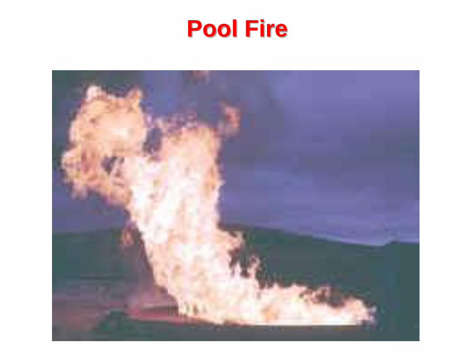
Pool Fire

Pool Fire Model
• Burgess and Hertzberg
m.
0.001H c
H v cp Tb Ta
(K) liquid the of etemperatur initial the isT
(K) etemperatur boiling liquid the is T
).K(kJ.kg liquid the ofcapacity heat the is C
(kJ/kg) point boiling its at fuel of onvaporisati of heat the is H
(kJ/kg) point boiling its at fuel of combustion of heat the is H
skgm in rate burning mass the is m Here,
a
b
1-1-
P
V
C
-1-2
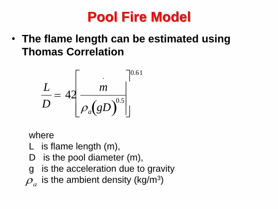
Pool Fire Model
• The flame length can be estimated using
Thomas Correlation
L
D 42
m.
a gD 0.5
0.61
where
L is flame length (m),
D is the pool diameter (m),
g is the acceleration due to gravity
is the ambient density (kg/m3)
a

Explosion Models

BLEVE
B L E VO
I
L
I
N
G
I
Q
U
I
D
X
P
A
N
D
I
N
G
X
P
L
O
S
I
O
N
S
EA
P
O
R
BLEVE is a consequence of holding a pressurized flammable liquids above its boiling point.

Causes of BLEVE
• The immediate cause of the BLEVE is rupture of the
container. If the pressure inside the vessel exceeds the
outside strength of the walls the vessel will fail.
• If the vessel is overfilled and expansion (due to boiling
of liquid) results in a heavy hydrostatic pressure.
• If the vessel is weakened by mechanical damage or by
high temperature resulting from immersion in a fire
then failure can occur.

Mechanism of BLEVE
When BLEVE is initiated, the
liquid boils off rapidly producing a
reaction which turns parts of the
ruptured vessel into rockets which
can travel 2500 ft or more.
The liquid can take fire if it is
flammable and burning material
can spread over a large area. If the
gas or liquid mixes with air a
vapour cloud explosion can occur.

Mathematical Model for BLEVE
• There are many models describing BLEVE. One
such model is given below.
t10 0.60(Wtot )1
6
D 1.836 W 1
3
Here
t10 is the lift-off time in seconds,
Wtot is the total weight of combustibles and air,
D is the maximum diameter of fireball and
W is the weight of combustibles

U V C E
N
C
O
N
F
I
N
E
D
A
P
O
R
L
O
U
D
X
P
L
O
S
I
O
N
S
Vapour Cloud Explosion
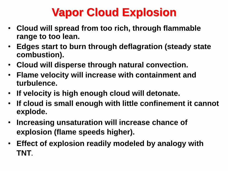
Vapor Cloud Explosion
• Cloud will spread from too rich, through flammable range to too lean.
• Edges start to burn through deflagration (steady state combustion).
• Cloud will disperse through natural convection.
• Flame velocity will increase with containment and turbulence.
• If velocity is high enough cloud will detonate.
• If cloud is small enough with little confinement it cannot explode.
• Increasing unsaturation will increase chance of
explosion (flame speeds higher).
• Effect of explosion readily modeled by analogy with
TNT.

• Size of Clouds
– probability of finding ignition source
– likelihood of generating any overpressure
– magnitude of overpressure
• Cloud composition
– Highly unsaturated molecules are bad
• Weather
– Stable atmospheres lead to large clouds.
– Low wind speed encourages large clouds.
• Source
– flashing liquids seem to give high overpressure
Factors Favoring High Over Pressures

70
160
290
470
670
940
1
2
5
10
15
20
30
35
50
65
Peak
Overpressure
psi
Equivalent
Wind Velocity
mph
Knock personnel down
Rupture eardrums
Damage lungs
Threshold fatalities
50% fatalities
99% fatalities
Effects
Impact of VCEs on People

Impact of VCEs on Facilities
Peak
Overpressure
psi
Typical Damage
0.5 - 1 Glass windows break
1-2
2-3
Common siding types fail:
- corrugated asbestos shatters
- corrugated steel panel joints fail
- wood siding blows in
Unreinforced concrete, cinder block walls fail
3-4
5
Self-framed steel panel buildings collapse
Oil storage tanks rupture
Utility poles snap
7
7-8
Loaded rail cars overturn
Unreinforced brick walls fail

Distance Comparison
1
2
5
10
20
50
100
200
500
1000
INVENTORY
(tons)
18
36
60
90
130
200
280
400
600
820
BLEVE
120
150
200
250
310
420
530
670
900
1150
UVCE
20
30
36
50
60
100
130
FIRE
Distance
in Meters

Mechanical Explosion – Gas Filled Vessel
• Lees (1996) prefers to use Brode equation for the
estimation of the explosion energy of gas-filled vessels.
The following version of the Brode equation in terms of
TNT equivalence has been given in the Second Canvey
Report (HSE, 1981)
E 1.43x10⁶P1 P0 V 1
E is the explosion energy (ton of TNT),
P1 is the initial pressure in the vessel (kPa)
P0 is the pressure of the surrounding (kPa)
V is the volume of the vessel (m3).
The volume can be calculated using Ideal gas law.

Chemical Explosion
• Explosion due to exothermic reaction occurring
internally
• such reaction may involve decomposition of unstable
substances, polymerization of monomers, or
combustion of fuel – oxidant mixtures
• heating and increase of mole- number result in a rise in
pressure to the bursting point of the vessel, etc.
• explosives decomposes quickly that confinement of
the development of pressure are self-imposed
• fire may or may not ensue.

Energy of Explosion
• It is important that the energy of explosion be
estimated correctly
• Use appropriate model to estimate energy
– Combustion
– Heat of reaction
– Physical explosion energy
– etc

TNT Equivalent
• TNT equivalency is a simple method for equating a
known energy of a combustible fuel to an equivalent
mass of TNT.
• The approach is based on the assumption that an
exploding fuel mass behaves like exploding TNT on an
equivalent energy basis.

The equivalent mass of TNT
• A typical value for energy of explosion of TNT is 1120
calories/gram. The heat of combustion for the flammable gas
can be used in place of the energy of explosion for the
combustible gas.
TNT
CTNT
E
Hmm
TNT of explosion ofenergy the is E
nhydrocarbo of mass the is m
(unitless) efficiency explosion empirical the is
(mass) TNT of mass equivalent the is m
TNT
TNT

TNT Equivalent
• The procedure to estimate the damage associated with
an explosion using the TNT equivalent method is as
follows :
– Determine the total amount of flammable material involved in
the explosion.
– Estimate the explosion efficiency and calculate the equivalent
mass of TNT.
– Use the scaling law to estimate the peak side on overpressure.
– Estimate the damage for common structures and process
equipment using table guide.

Multi-Energy Models for Blast Effects
• Recent developments in science suggest too many unknowns for
simple TNT model.
• Key variables to over pressure effect are:
– Quantity of combustant in explosion
– Congestion/confinement for escape of combustion products
– Number of serial explosions
• Multi-energy is consistent with models and pilot explosions.

ALOHA
• A software offered free of charge by the US
EPA.
– Can model dispersion, fire and explosion
• Part of Cameo Suite

Aloha