Embed Size (px)
Citation preview
FIRE FIGHTING ROBOT COMPETITION
ENGINEERS
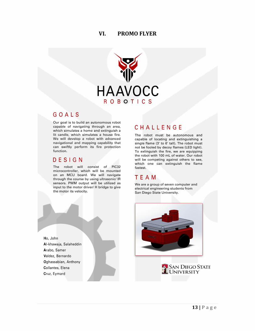
Ho, John Al-khawaja, Salaheddin Arabo, Samer Valdez Bernardo Oghassabian, Anthony Collantes, Elena Cruz, Eymard
1 | P a g e
Table of Contents
I. Introduction ………………..………………………………….…………………….…….2
Abstract ……………………………………………………………………..…..….2 Project Description …………………………………………….......................2 HAAVOCC Functions …………………………………………………………..2
II. Design ……………………………………………………………………………………..…3 Autonomous Design …………………………………………………………...3 Mobility ……………………………………………………………………………..4 Firefighting Capability ………………………………………………………..4 Support Circuitry ……………………………………………………………….4 Mock Up Illustration …………………………………………………………..5 Performance Requirements ………………………………………………..5
III. Testing and Verification ……………………………………………………………6 Hardware ………………………………………………………………………….6
Ultrasonic Sensor ..………………………………………………………...6 IR Phototransistor ………………………………………………………...6 Motors ………….………………………………………………………………6 Motor Encoder ……………………………………………………………...7 Fire Fighting Agent ……………………………………...………….…….7
Software ……………………………………………………….............................7 BenchMarks ……………………………………………………….....................8
IV. Program Management ……………………………………………………9 V. Budget ………………………………………………………..............................12 VI. Promo Flyer ………………………………………………………................13
2 | P a g e
I. INTRODUCTION
Abstract
This robotic project is geared to meet the competition challenge of building an autonomous robot capable of navigating through an arena that simulates a home, find a lit candle that represents a house fire, and extinguish the fire in the fastest possible time. This scenario demonstrates what an autonomous robot is capable of in a real world fire inside a home. Our goal is to develop a robot with advanced navigational and mapping capability that can swiftly perform its fire protection function. Robots with such capability can become a major difference in preventing human and infrastructure casualties caused by fires. Project Description
The Fire Fighting Robot competition is comprised of two phases, both in which each robot must locate and extinguish a single flame source from a candle (3” to 6” tall) located in the arena as quickly as possible and avoid decoy candles (LED light). The robot must perform these tasks autonomously and will be equipped with 100mL of water as its Fire Fighting agent, which can be deployed by any method. Deploying the firefighting agent on a decoy will cause a run to be terminated. In phase 1, robots will traverse the arena alone. In phase 2 the course will be reconfigured and all competing robots will traverse the arena simultaneously. Engaging other robots is allowed and encouraged.
HAAVOCC Robotics’ goal is to outperform all competitors in every aspect of the competition. Based on competition rules, swiftness and accuracy is the key to winning. The ability to precisely navigate and actively map the arena is the keystone of our design—and precision is speed. To achieve precise navigation, we aim to employ an array of sensors. We will utilize ultrasonic sensors to detect obstacles, IR phototransistor sensors to detect flame, and the motor encoders determine distance and direction travelled. This sensor array will be used to provide real-time surroundings feedback into a microcontroller where AEENCA (Advanced Environmental Evaluation, Navigation, and Control Algorithm) resides—our secret sauce.
HAAVOCC Functions:
1. Precision Navigation
2. Advanced Obstacle Detection and Avoidance
3. Advanced Fire Detection
4. State of the Art Fire Extinguishing Method
5. Swift Mobility
3 | P a g e
II. DESIGN
Figure 1: HAAVOCC FUNCTIONAL BLOCK DIAGRAM
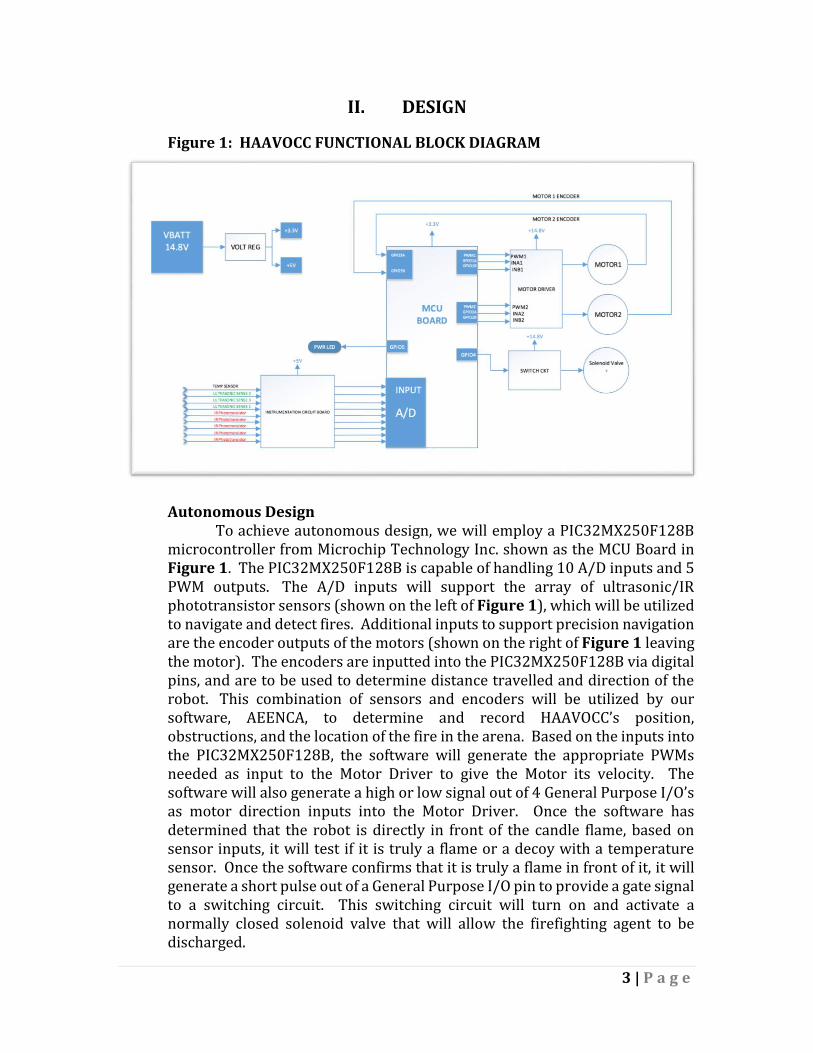
Autonomous Design
To achieve autonomous design, we will employ a PIC32MX250F128B microcontroller from Microchip Technology Inc. shown as the MCU Board in Figure 1. The PIC32MX250F128B is capable of handling 10 A/D inputs and 5 PWM outputs. The A/D inputs will support the array of ultrasonic/IR phototransistor sensors (shown on the left of Figure 1), which will be utilized to navigate and detect fires. Additional inputs to support precision navigation are the encoder outputs of the motors (shown on the right of Figure 1 leaving the motor). The encoders are inputted into the PIC32MX250F128B via digital pins, and are to be used to determine distance travelled and direction of the robot. This combination of sensors and encoders will be utilized by our software, AEENCA, to determine and record HAAVOCC’s position, obstructions, and the location of the fire in the arena. Based on the inputs into the PIC32MX250F128B, the software will generate the appropriate PWMs needed as input to the Motor Driver to give the Motor its velocity. The software will also generate a high or low signal out of 4 General Purpose I/O’s as motor direction inputs into the Motor Driver. Once the software has determined that the robot is directly in front of the candle flame, based on sensor inputs, it will test if it is truly a flame or a decoy with a temperature sensor. Once the software confirms that it is truly a flame in front of it, it will generate a short pulse out of a General Purpose I/O pin to provide a gate signal to a switching circuit. This switching circuit will turn on and activate a normally closed solenoid valve that will allow the firefighting agent to be discharged.
4 | P a g e
Mobility
HAAVOCC is designed to achieve a maximum velocity of 2 feet per second. To perform to this standard, a Dual Motor Driver Carrier and 2 Motors powered by a 14.8 VDC battery coupled to 3-inch diameter wheels are employed. The system is designed with skid steering as a method of maneuvering. Skid steering allows HAAVOCC to make tight turns swiftly.
Firefighting Capability
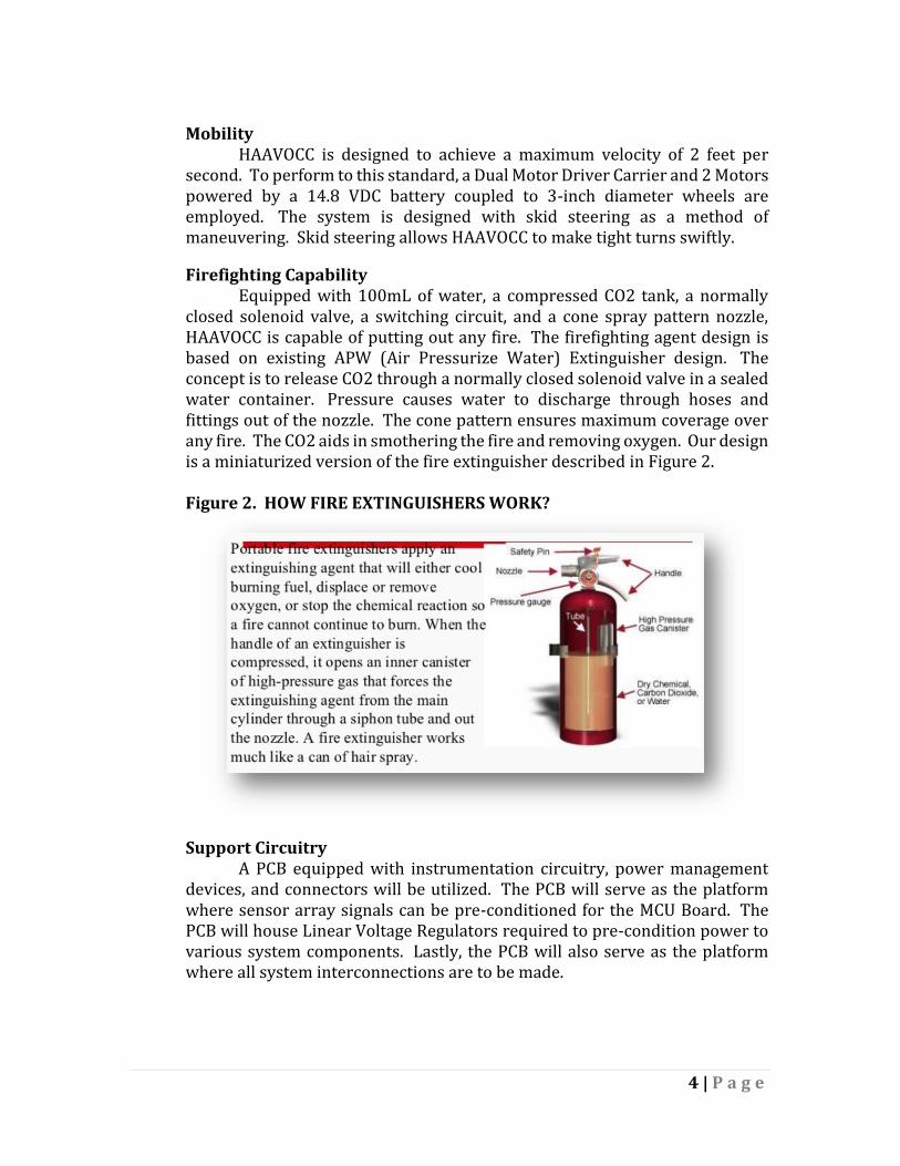
Equipped with 100mL of water, a compressed CO2 tank, a normally closed solenoid valve, a switching circuit, and a cone spray pattern nozzle, HAAVOCC is capable of putting out any fire. The firefighting agent design is based on existing APW (Air Pressurize Water) Extinguisher design. The concept is to release CO2 through a normally closed solenoid valve in a sealed water container. Pressure causes water to discharge through hoses and fittings out of the nozzle. The cone pattern ensures maximum coverage over any fire. The CO2 aids in smothering the fire and removing oxygen. Our design is a miniaturized version of the fire extinguisher described in Figure 2. Figure 2. HOW FIRE EXTINGUISHERS WORK?
Support Circuitry
A PCB equipped with instrumentation circuitry, power management devices, and connectors will be utilized. The PCB will serve as the platform where sensor array signals can be pre-conditioned for the MCU Board. The PCB will house Linear Voltage Regulators required to pre-condition power to various system components. Lastly, the PCB will also serve as the platform where all system interconnections are to be made.
5 | P a g e
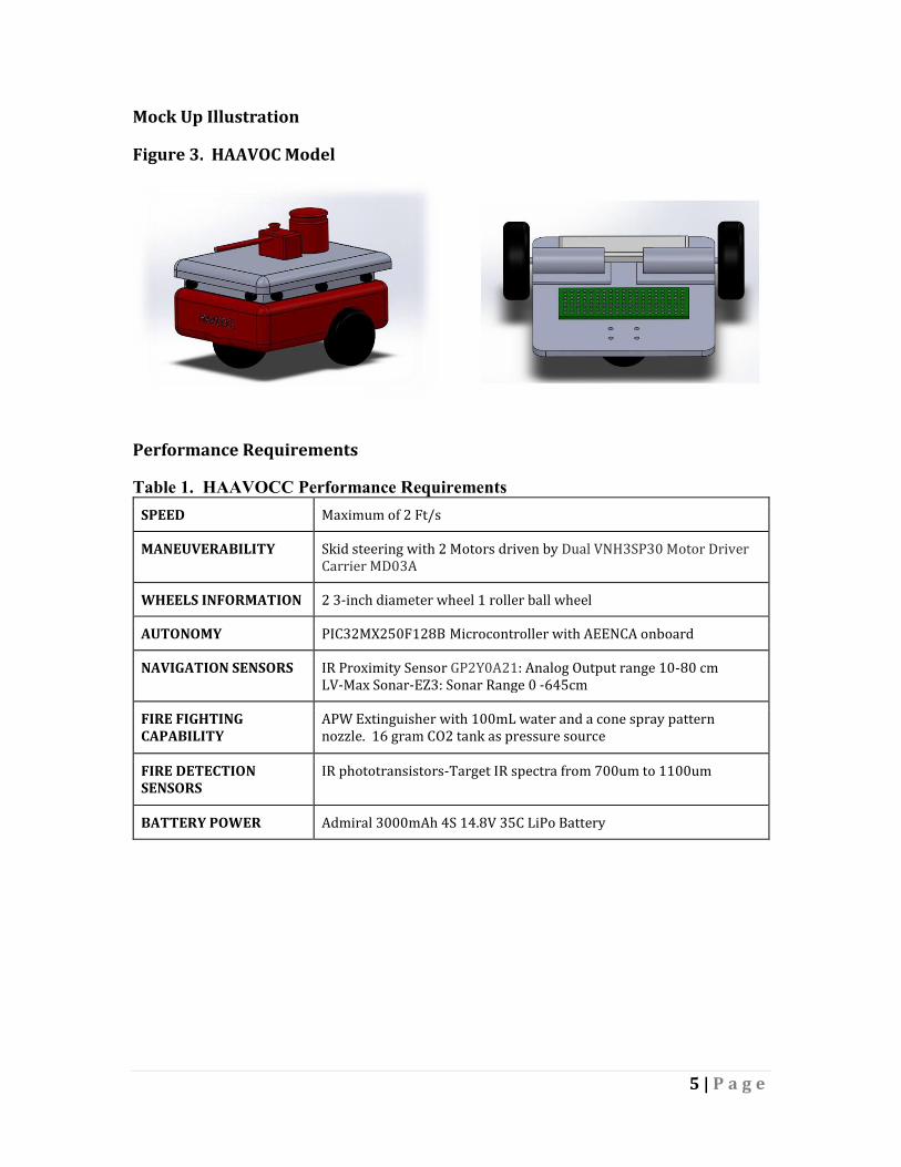
Mock Up Illustration
Figure 3. HAAVOC Model
Performance Requirements
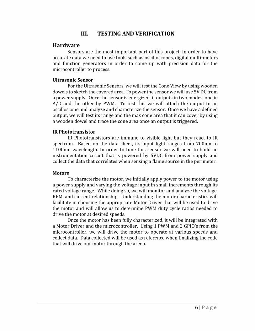
Table 1. HAAVOCC Performance Requirements
SPEED Maximum of 2 Ft/s
MANEUVERABILITY Skid steering with 2 Motors driven by Dual VNH3SP30 Motor Driver Carrier MD03A
WHEELS INFORMATION 2 3-inch diameter wheel 1 roller ball wheel
AUTONOMY PIC32MX250F128B Microcontroller with AEENCA onboard
NAVIGATION SENSORS IR Proximity Sensor GP2Y0A21: Analog Output range 10-80 cm LV-Max Sonar-EZ3: Sonar Range 0 -645cm
FIRE FIGHTING CAPABILITY
APW Extinguisher with 100mL water and a cone spray pattern nozzle. 16 gram CO2 tank as pressure source
FIRE DETECTION SENSORS
IR phototransistors-Target IR spectra from 700um to 1100um
BATTERY POWER Admiral 3000mAh 4S 14.8V 35C LiPo Battery
6 | P a g e
III. TESTING AND VERIFICATION
Hardware Sensors are the most important part of this project. In order to have
accurate data we need to use tools such as oscilloscopes, digital multi-meters and function generators in order to come up with precision data for the microcontroller to process.
Ultrasonic Sensor
For the Ultrasonic Sensors, we will test the Cone View by using wooden dowels to sketch the covered area. To power the sensor we will use 5V DC from a power supply. Once the sensor is energized, it outputs in two modes, one in A/D and the other by PWM. To test this we will attach the output to an oscilloscope and analyze and characterize the sensor. Once we have a defined output, we will test its range and the max cone area that it can cover by using a wooden dowel and trace the cone area once an output is triggered.
IR Phototransistor
IR Phototransistors are immune to visible light but they react to IR spectrum. Based on the data sheet, its input light ranges from 700nm to 1100nm wavelength. In order to tune this sensor we will need to build an instrumentation circuit that is powered by 5VDC from power supply and collect the data that correlates when sensing a flame source in the perimeter. Motors
To characterize the motor, we initially apply power to the motor using a power supply and varying the voltage input in small increments through its rated voltage range. While doing so, we will monitor and analyze the voltage, RPM, and current relationship. Understanding the motor characteristics will facilitate in choosing the appropriate Motor Driver that will be used to drive the motor and will allow us to determine PWM duty cycle ratios needed to drive the motor at desired speeds.
Once the motor has been fully characterized, it will be integrated with a Motor Driver and the microcontroller. Using 1 PWM and 2 GPIO’s from the microcontroller, we will drive the motor to operate at various speeds and collect data. Data collected will be used as reference when finalizing the code that will drive our motor through the arena.
7 | P a g e
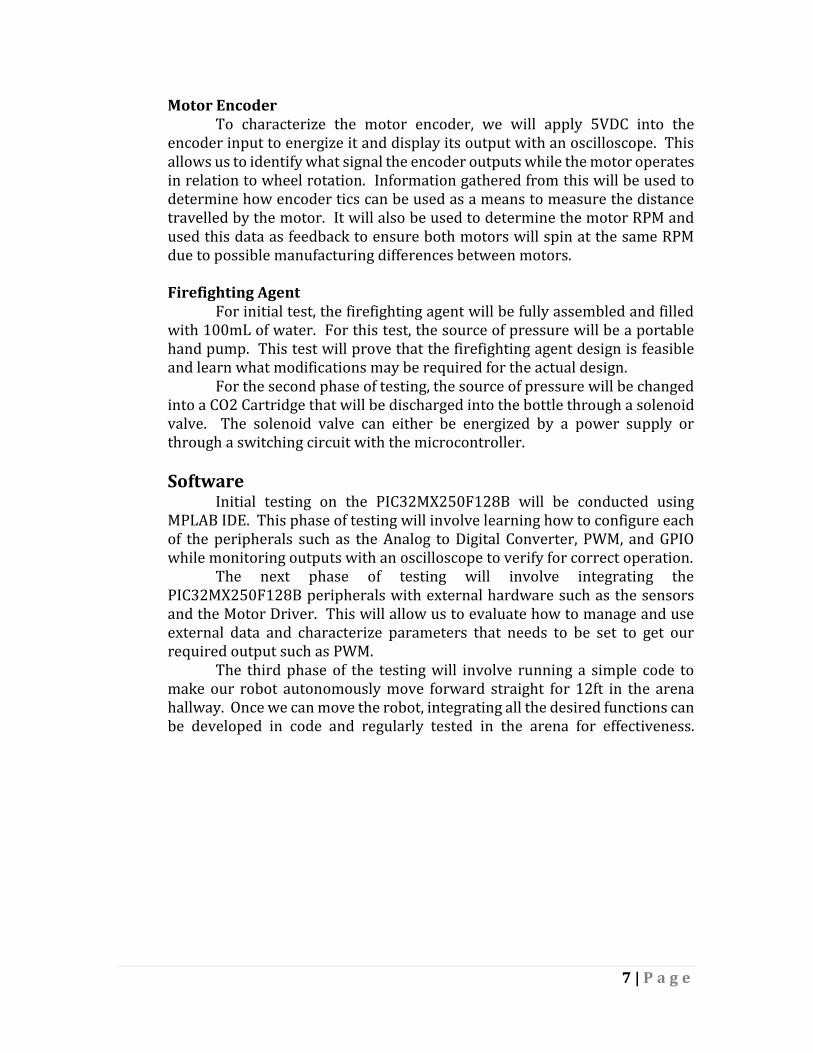
Motor Encoder To characterize the motor encoder, we will apply 5VDC into the
encoder input to energize it and display its output with an oscilloscope. This allows us to identify what signal the encoder outputs while the motor operates in relation to wheel rotation. Information gathered from this will be used to determine how encoder tics can be used as a means to measure the distance travelled by the motor. It will also be used to determine the motor RPM and used this data as feedback to ensure both motors will spin at the same RPM due to possible manufacturing differences between motors. Firefighting Agent For initial test, the firefighting agent will be fully assembled and filled with 100mL of water. For this test, the source of pressure will be a portable hand pump. This test will prove that the firefighting agent design is feasible and learn what modifications may be required for the actual design. For the second phase of testing, the source of pressure will be changed into a CO2 Cartridge that will be discharged into the bottle through a solenoid valve. The solenoid valve can either be energized by a power supply or through a switching circuit with the microcontroller.
Software
Initial testing on the PIC32MX250F128B will be conducted using MPLAB IDE. This phase of testing will involve learning how to configure each of the peripherals such as the Analog to Digital Converter, PWM, and GPIO while monitoring outputs with an oscilloscope to verify for correct operation.
The next phase of testing will involve integrating the PIC32MX250F128B peripherals with external hardware such as the sensors and the Motor Driver. This will allow us to evaluate how to manage and use external data and characterize parameters that needs to be set to get our required output such as PWM.
The third phase of the testing will involve running a simple code to make our robot autonomously move forward straight for 12ft in the arena hallway. Once we can move the robot, integrating all the desired functions can be developed in code and regularly tested in the arena for effectiveness.
8 | P a g e
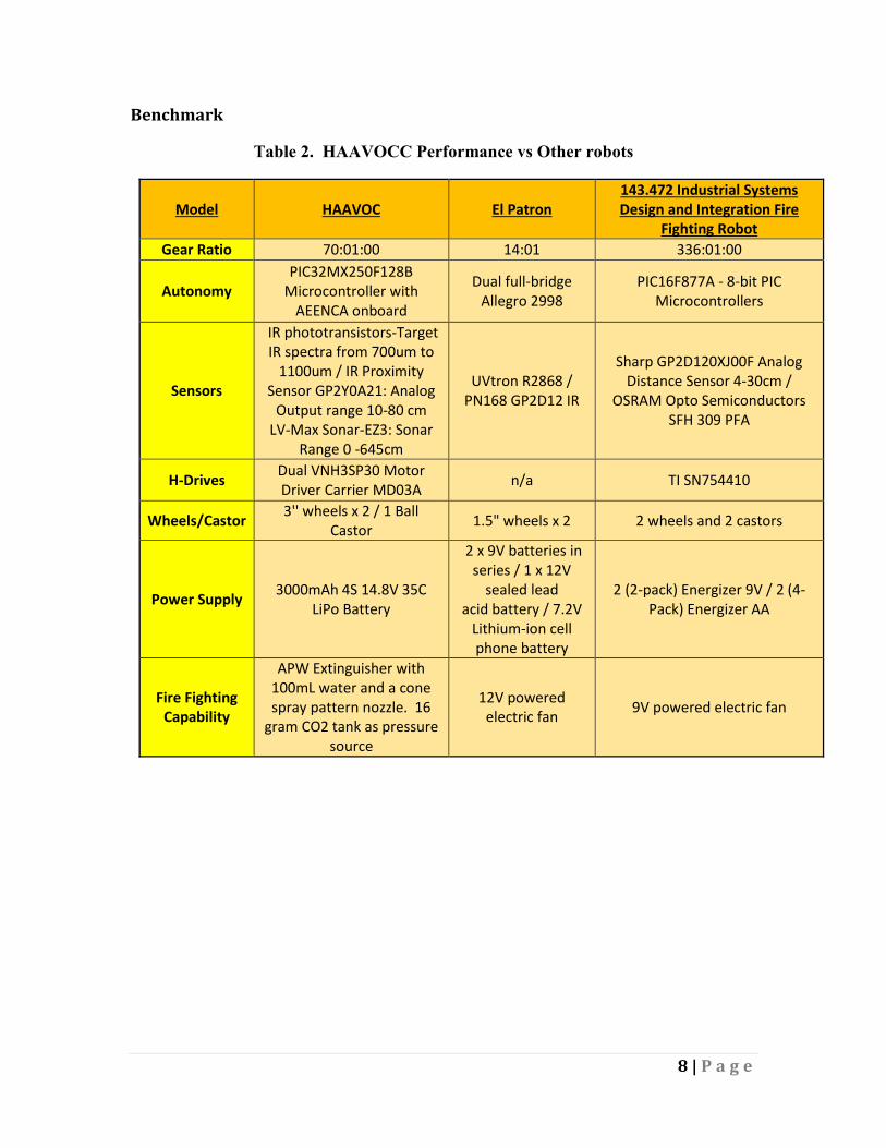
Benchmark
Table 2. HAAVOCC Performance vs Other robots
Model HAAVOC El Patron 143.472 Industrial Systems Design and Integration Fire
Fighting Robot
Gear Ratio 70:01:00 14:01 336:01:00
Autonomy PIC32MX250F128B
Microcontroller with AEENCA onboard
Dual full-bridge Allegro 2998
PIC16F877A - 8-bit PIC Microcontrollers
Sensors
IR phototransistors-Target IR spectra from 700um to
1100um / IR Proximity Sensor GP2Y0A21: Analog
Output range 10-80 cm LV-Max Sonar-EZ3: Sonar
Range 0 -645cm
UVtron R2868 / PN168 GP2D12 IR
Sharp GP2D120XJ00F Analog Distance Sensor 4-30cm /
OSRAM Opto Semiconductors SFH 309 PFA
H-Drives Dual VNH3SP30 Motor Driver Carrier MD03A
n/a TI SN754410
Wheels/Castor 3'' wheels x 2 / 1 Ball
Castor 1.5" wheels x 2 2 wheels and 2 castors
Power Supply 3000mAh 4S 14.8V 35C
LiPo Battery
2 x 9V batteries in series / 1 x 12V
sealed lead acid battery / 7.2V
Lithium-ion cell phone battery
2 (2-pack) Energizer 9V / 2 (4-Pack) Energizer AA
Fire Fighting Capability
APW Extinguisher with 100mL water and a cone spray pattern nozzle. 16
gram CO2 tank as pressure source
12V powered electric fan
9V powered electric fan
9 | P a g e
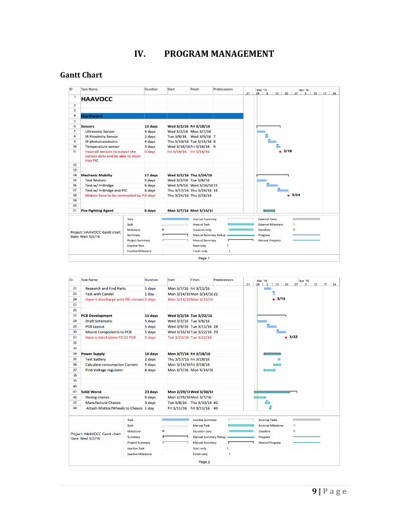
IV. PROGRAM MANAGEMENT
Gantt Chart
10 | P a g e
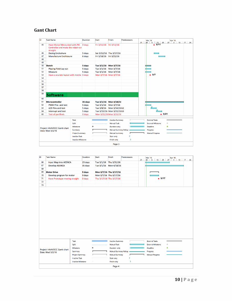
Gant Chart
11 | P a g e
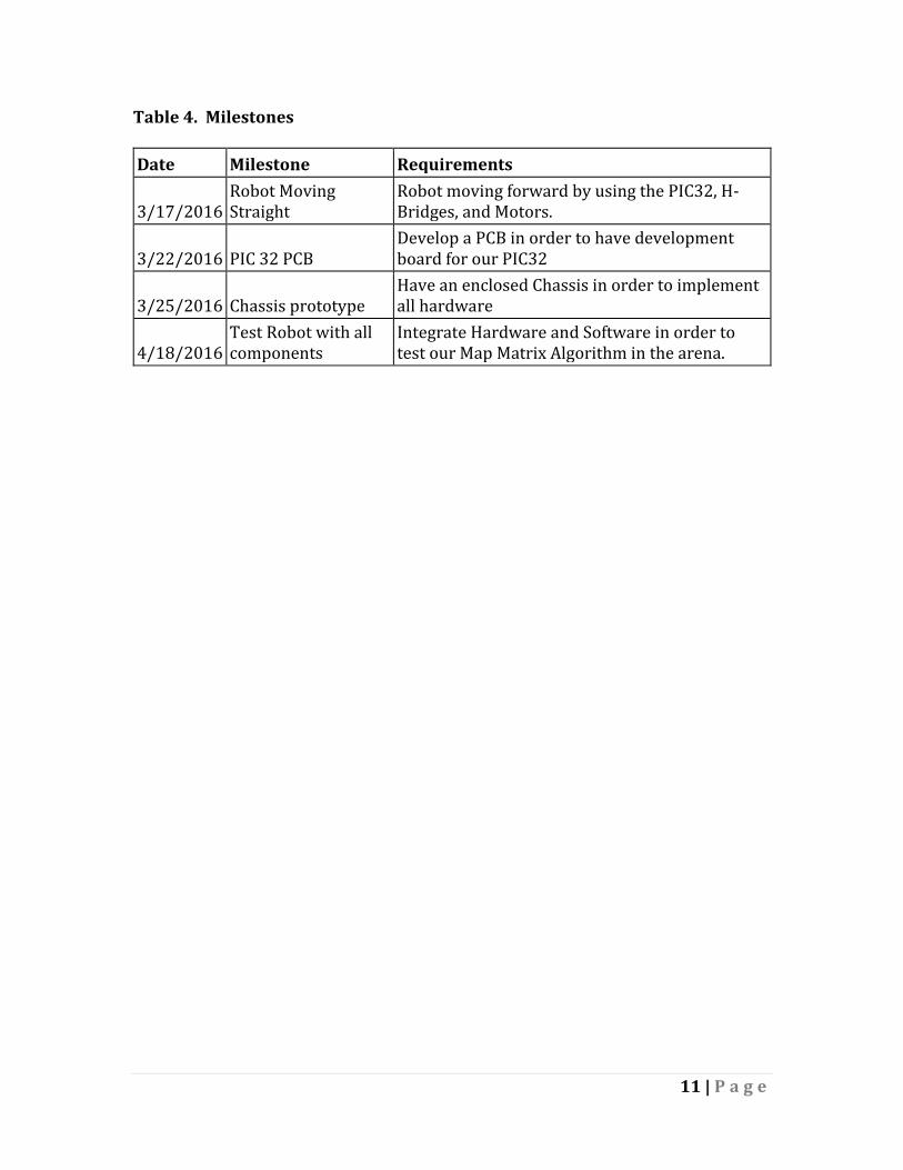
Table 4. Milestones
Date Milestone Requirements
3/17/2016 Robot Moving Straight
Robot moving forward by using the PIC32, H-Bridges, and Motors.
3/22/2016 PIC 32 PCB Develop a PCB in order to have development board for our PIC32
3/25/2016 Chassis prototype Have an enclosed Chassis in order to implement all hardware
4/18/2016 Test Robot with all components
Integrate Hardware and Software in order to test our Map Matrix Algorithm in the arena.
12 | P a g e
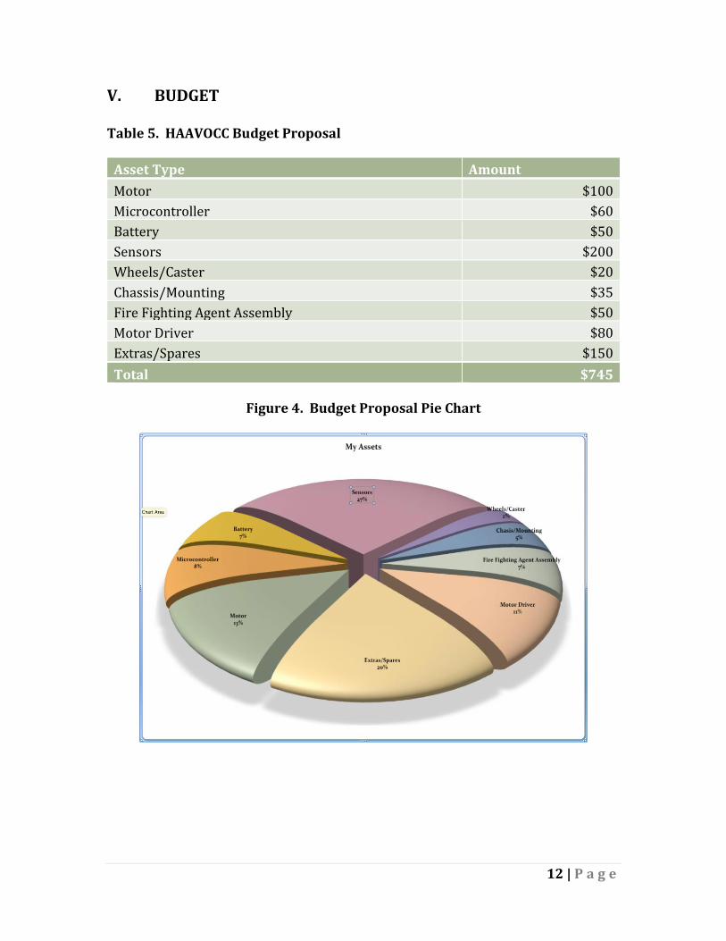
V. BUDGET
Table 5. HAAVOCC Budget Proposal
Asset Type Amount
Motor $100
Microcontroller $60
Battery $50
Sensors $200
Wheels/Caster $20
Chassis/Mounting $35
Fire Fighting Agent Assembly $50
Motor Driver $80
Extras/Spares $150
Total $745
Figure 4. Budget Proposal Pie Chart
13 | P a g e
VI. PROMO FLYER


![Micro Controller Based Fire Fighting Robot[1]](https://img.pdfslide.net/doc/110x75/55205991497959842f8b4a5b/micro-controller-based-fire-fighting-robot1.jpg)


![Fire Fighting Robot Rules[1]](https://img.pdfslide.net/doc/110x75/577d39241a28ab3a6b99233b/fire-fighting-robot-rules1.jpg)