Embed Size (px)
Citation preview

Project Proposal
Fire “Fighting” Competition
Engineering Team Abukar Abdirahim Erika Serrano Dan Bernstein Ryan Torres Maryann Dalal Joseph Villanueva Cody Nnamani
Submitted to: John Kennedy and Lal Tummala Design Co. Ltd, San Diego, CA
March 3, 2016
Sponsored By: Senior Design Project
1
TABLE OF CONTENTS
INTRODUCTION Abstract………………………………………………………………………………….... 2 Competition Description………………………………………..………………….... 2 System Description……………………………………………………………………. 3
DESIGN
Hardware Block Diagram and Software Flow Chart…………………..…….. 4-8 Solidworks Rendering……………………………………………………….......... 9-10 Performance Requirements………………………………………………............... 11
TESTING AND VERIFICATION
Testing Procedures………………………………………………………………….. 12-15 Benchmarks…………………………………………………………………………….. 15
PROJECT MANAGEMENT
Project Plan…………………………………………………………………………….... 16 Milestones………………………………………………………………………………... 17
BUDGET Cost Analysis…………………………………………………………………………….... 17
PROMOTIONAL FLYER……………………………..………………………………………. 18
2
INTRODUCTION
ABSTRACT
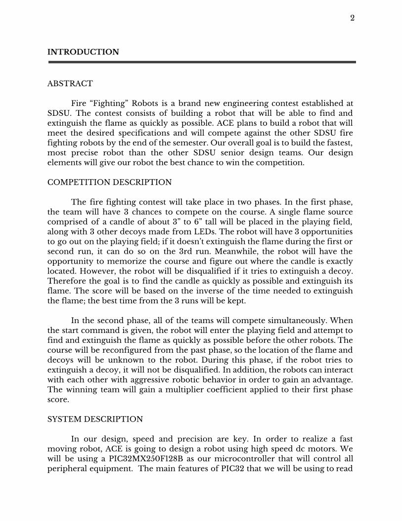
Fire “Fighting” Robots is a brand new engineering contest established at SDSU. The contest consists of building a robot that will be able to find and extinguish the flame as quickly as possible. ACE plans to build a robot that will meet the desired specifications and will compete against the other SDSU fire fighting robots by the end of the semester. Our overall goal is to build the fastest, most precise robot than the other SDSU senior design teams. Our design elements will give our robot the best chance to win the competition.
COMPETITION DESCRIPTION
The fire fighting contest will take place in two phases. In the first phase, the team will have 3 chances to compete on the course. A single flame source comprised of a candle of about 3” to 6” tall will be placed in the playing field, along with 3 other decoys made from LEDs. The robot will have 3 opportunities to go out on the playing field; if it doesn’t extinguish the flame during the first or second run, it can do so on the 3rd run. Meanwhile, the robot will have the opportunity to memorize the course and figure out where the candle is exactly located. However, the robot will be disqualified if it tries to extinguish a decoy. Therefore the goal is to find the candle as quickly as possible and extinguish its flame. The score will be based on the inverse of the time needed to extinguish the flame; the best time from the 3 runs will be kept.
In the second phase, all of the teams will compete simultaneously. When the start command is given, the robot will enter the playing field and attempt to find and extinguish the flame as quickly as possible before the other robots. The course will be reconfigured from the past phase, so the location of the flame and decoys will be unknown to the robot. During this phase, if the robot tries to extinguish a decoy, it will not be disqualified. In addition, the robots can interact with each other with aggressive robotic behavior in order to gain an advantage. The winning team will gain a multiplier coefficient applied to their first phase score. SYSTEM DESCRIPTION
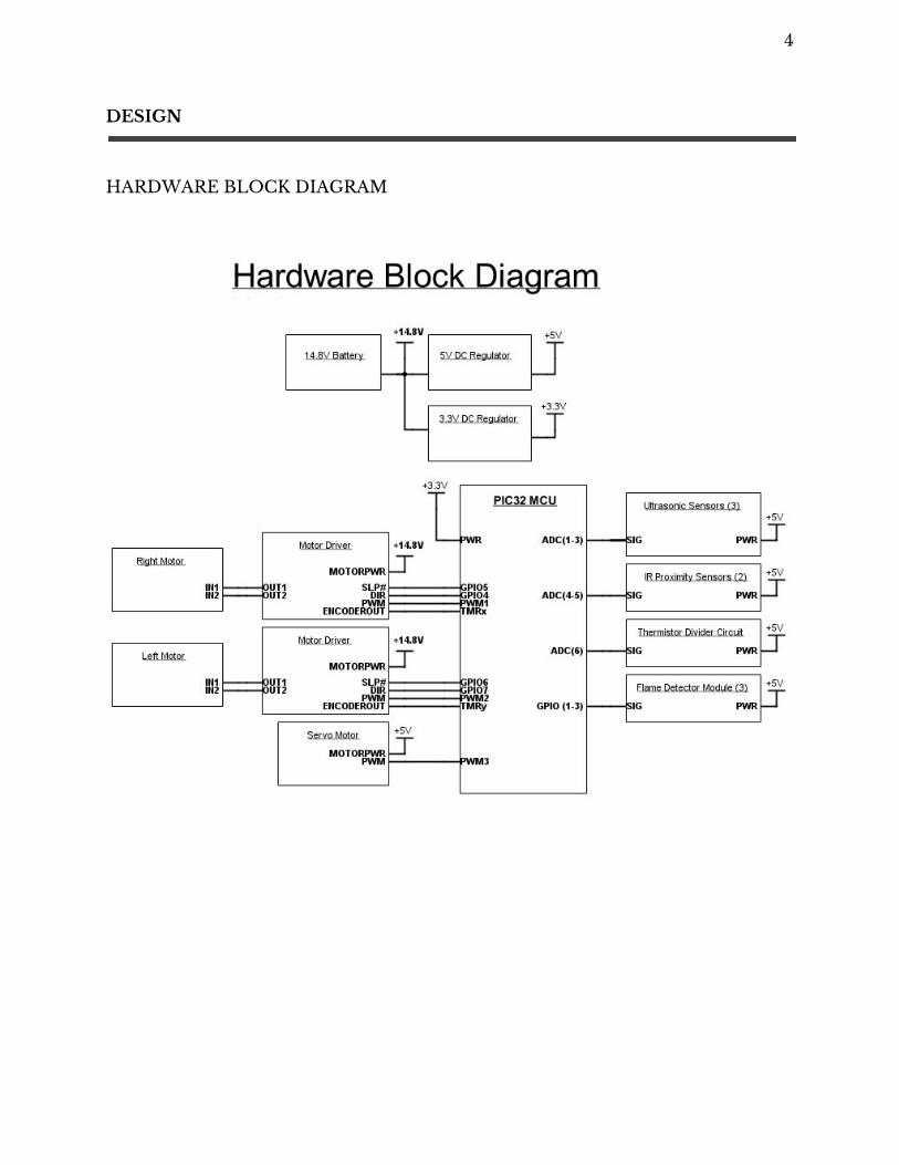
In our design, speed and precision are key. In order to realize a fast moving robot, ACE is going to design a robot using high speed dc motors. We will be using a PIC32MX250F128B as our microcontroller that will control all peripheral equipment. The main features of PIC32 that we will be using to read
3
our sensors and control our motors are PWM, ADC, and to use GPIOs in order to properly sense and interact with the competition course.
To make our robot perform the necessary functions, we will be incorporating feedback from high speed motor encoders, infrared proximity sensors, ultrasonic range finders, and IR flame detectors/phototransistors.
The infrared and proximity sensors will be sensing the distance to the walls of the course. These sensors will be used as feedback to the microprocessor to avoid collisions with the walls or other obstacles while moving through the course. The speed of the motor will be monitored and regulated by the use of the motor encoders.
Our primary method of extinguishing the candle will be to use a
mechanism similar to a crane. We will be using a damp rag suspended by string that is bound to an arm that extends in front of ACE. A DC motor will rotate a reel which the string is wound around in order to lower the rag onto the flame.
4
DESIGN
HARDWARE BLOCK DIAGRAM
5
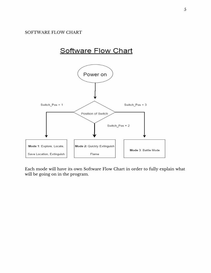
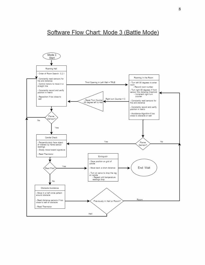
SOFTWARE FLOW CHART
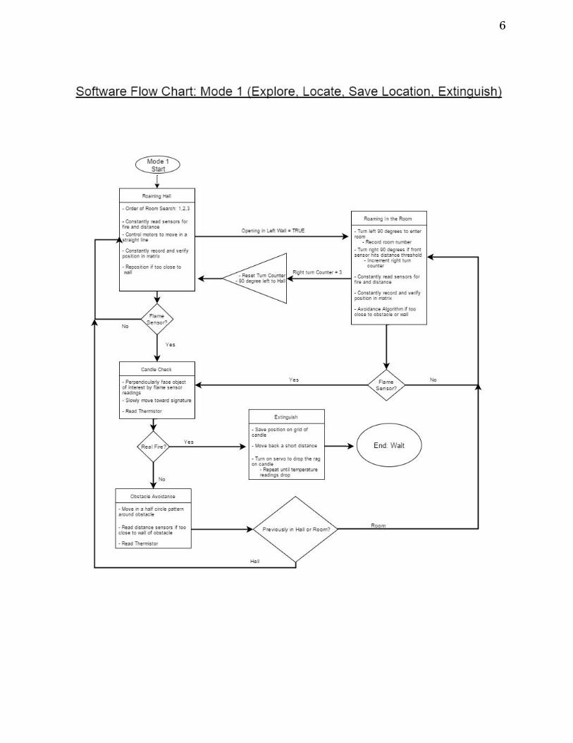
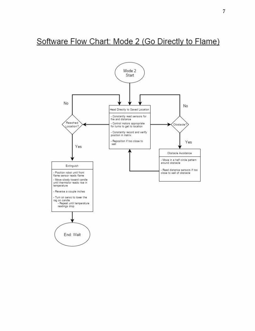
Each mode will have its own Software Flow Chart in order to fully explain what will be going on in the program.
6
7
8
9
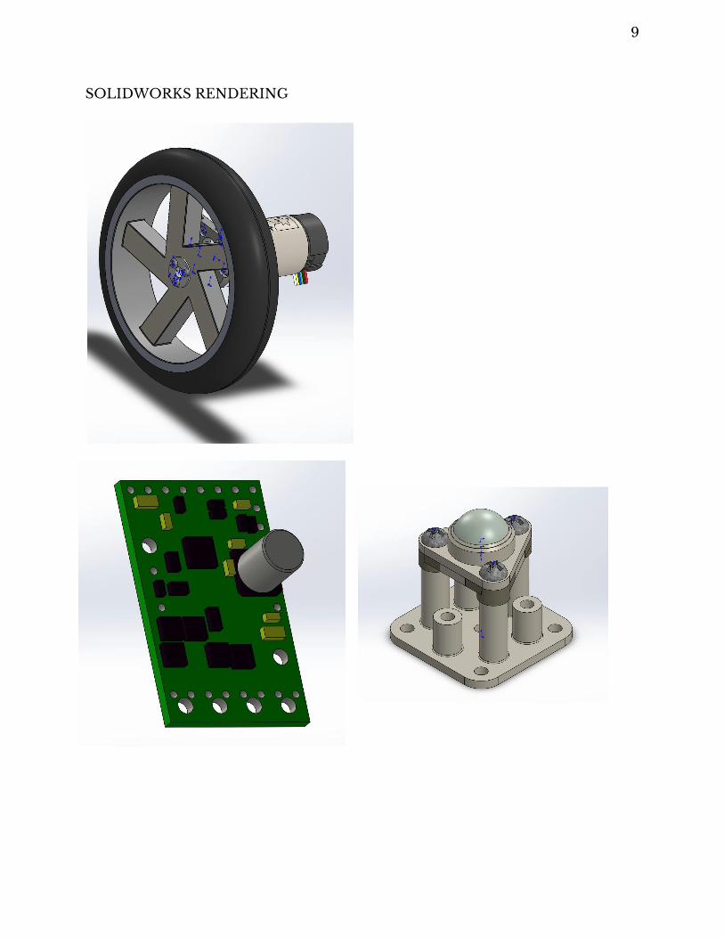
SOLIDWORKS RENDERING

10
11
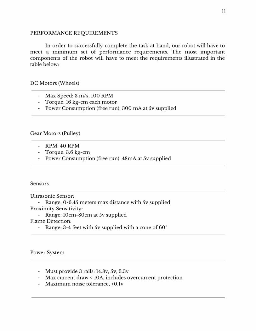
PERFORMANCE REQUIREMENTS
In order to successfully complete the task at hand, our robot will have to meet a minimum set of performance requirements. The most important components of the robot will have to meet the requirements illustrated in the table below: DC Motors (Wheels)
- Max Speed: 3 m/s, 100 RPM - Torque: 16 kg-cm each motor - Power Consumption (free run): 300 mA at 5v supplied
Gear Motors (Pulley)
- RPM: 40 RPM - Torque: 3.6 kg-cm - Power Consumption (free run): 48mA at 5v supplied
Sensors
Ultrasonic Sensor:
- Range: 0-6.45 meters max distance with 5v supplied Proximity Sensitivity:
- Range: 10cm-80cm at 5v supplied Flame Detection:
- Range: 3-4 feet with 5v supplied with a cone of 60°
Power System
- Must provide 3 rails: 14.8v, 5v, 3.3v - Max current draw < 10A, includes overcurrent protection - Maximum noise tolerance, +0.1v
12
TESTING AND VERIFICATION
TESTING PROCEDURES
The results from the testing shall verify how reliable the fire extinguishing robot ACE is able to solve the course and distinguish the difference between a candle’s flame versus an LED turned on, while at the same time cruising the course at the fastest time possible to extinguish the candle’s flame. Hardware Testing
When testing the hardware, each component will be tested individually in order to familiarize ourselves the functionality of the component as well as having the component function properly and provide us with the necessary functionality we desire.
To test the motor, we will test a geared motor with an encoder at no load to understand how the encoder operates in various voltages. The motor power input will vary from 0v to a little past the 12v max in order to observe the capability of the motor, while the encoder attached to the motor will have a fixed voltage of 5v and the output pin.
A third geared motor will be tested however with a smaller dimension that will be used to extinguishing the flame by lowing the cloth onto the flame, to do so we will need to vary the voltages in which we can calculate the RPM for the desired speed to lower the cloth.
The motor drivers will be tested by inputting both power supplies, one to represent the voltage input of the motor and the other a 3.3v to the board. However we will also input a signal via a function generator with a variation of duty cycle up to 80% for flexibility.
As for sensors we will test a variety of sensors that are capable to locate the flame and distinguish the flame from an LED in addition to having the robot navigate the course smoothly.
First, will be a pair of ultrasonic sensors (HC-SR04 and Maxbotix). HC-SR04 will be connected to a power supply at 5V and a wave generator sending a 20 kHz signal at 20% duty cycle in order to read the echo signal as well as the pulse width of the output. With this sensor it is crucial to test the range and the angle of the sensor in order to meet the specs from the data sheet and tune it
13
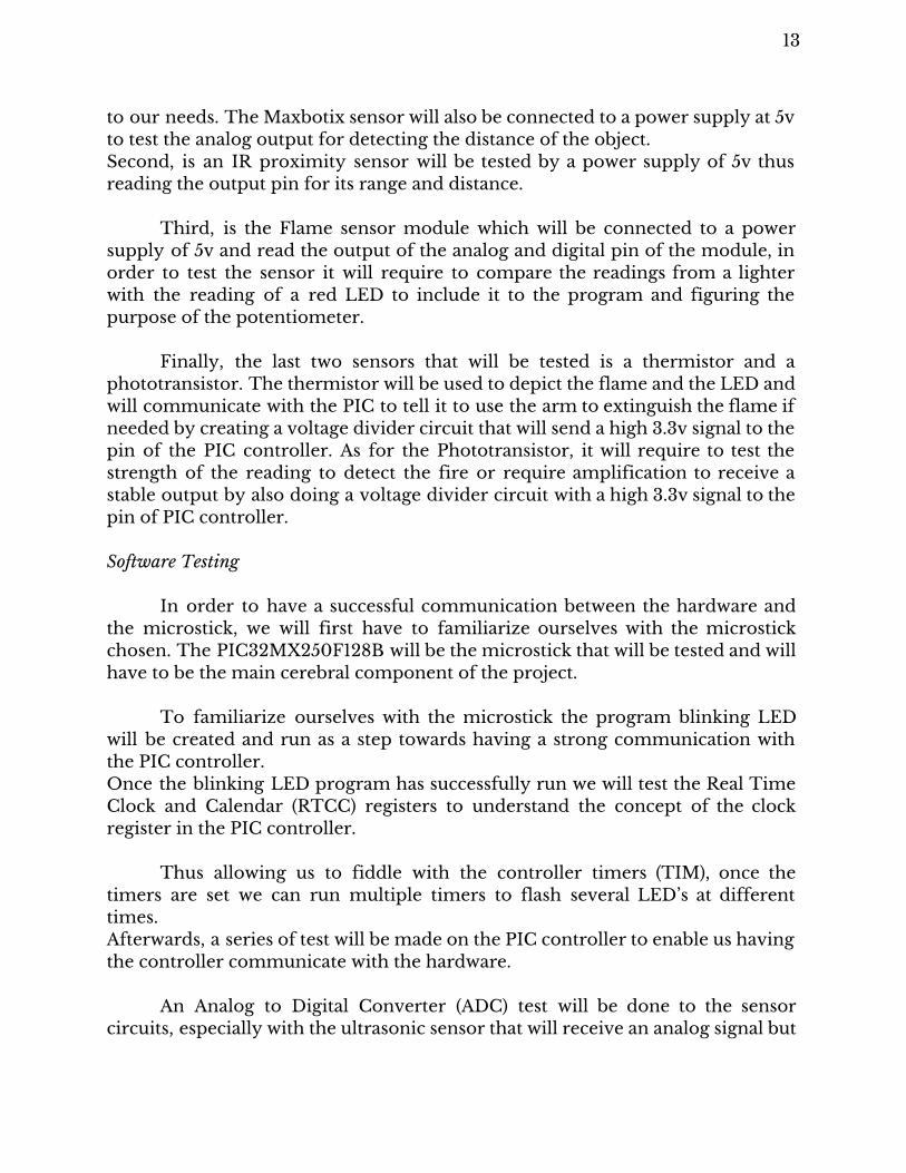
to our needs. The Maxbotix sensor will also be connected to a power supply at 5v to test the analog output for detecting the distance of the object. Second, is an IR proximity sensor will be tested by a power supply of 5v thus reading the output pin for its range and distance.
Third, is the Flame sensor module which will be connected to a power supply of 5v and read the output of the analog and digital pin of the module, in order to test the sensor it will require to compare the readings from a lighter with the reading of a red LED to include it to the program and figuring the purpose of the potentiometer.
Finally, the last two sensors that will be tested is a thermistor and a phototransistor. The thermistor will be used to depict the flame and the LED and will communicate with the PIC to tell it to use the arm to extinguish the flame if needed by creating a voltage divider circuit that will send a high 3.3v signal to the pin of the PIC controller. As for the Phototransistor, it will require to test the strength of the reading to detect the fire or require amplification to receive a stable output by also doing a voltage divider circuit with a high 3.3v signal to the pin of PIC controller. Software Testing
In order to have a successful communication between the hardware and the microstick, we will first have to familiarize ourselves with the microstick chosen. The PIC32MX250F128B will be the microstick that will be tested and will have to be the main cerebral component of the project.
To familiarize ourselves with the microstick the program blinking LED will be created and run as a step towards having a strong communication with the PIC controller. Once the blinking LED program has successfully run we will test the Real Time Clock and Calendar (RTCC) registers to understand the concept of the clock register in the PIC controller.
Thus allowing us to fiddle with the controller timers (TIM), once the timers are set we can run multiple timers to flash several LED’s at different times. Afterwards, a series of test will be made on the PIC controller to enable us having the controller communicate with the hardware.
An Analog to Digital Converter (ADC) test will be done to the sensor circuits, especially with the ultrasonic sensor that will receive an analog signal but
14
needs to be converted to digital to the controller and thus recorded the feedback given.
A PWM test will also be done since we are using motors that requires a PWM to function as well as the Motor Driver. The motor driver needs a PWM input to be able it to change the speed of the geared motors as well affect the motor driver’s direction and to count the distance that has been traveled using the feedback of the encoder.
Finally, ISR will be tested to interrupt the sensors LED blinking as well as being used to recording the mapping program to have the robot know where it is located. Notably, interrupts will also be tested on the motor driver when navigating the course. Testing Procedure for a completed system
Once we have done the individual testing between the hardware and software, it is time to test them together as a completed functional system known as the ACE robot. Furthermore, the test procedures will be done in step in order to pinpoint any errors we may encounter.
The geared motors and the motor drivers need to work together as one to output an identical speed in both motors as well as the same direction. However, we also want the motors to rotate the robot to navigate the robot successfully. In order to so, both the motor driver and the PIC controller has to coexist allowing us to send back and forward signal to the motor via the motor drive and the PIC by having the PIC enable the PWM and directional pin.
Once the motors have been successfully connected to the PIC, now the PIC will need to communicate with the sensors as one when scanning the room and the rest of the course for a candle’s flame or the LED as the decoy in addition to navigating the room without problems in order to so it will require the use on the Analog to Digital Converter (ADC) and well as a battery source.
Afterwards, a rough draft of a program will be tested to map the course and record via its memory the distance it has traveled and needs to travel while having the sensors on and the motors functionally properly.
In order to have the ACE running we will need a battery source, we are consider a source in the range of 12-15v supplying the robot but also have voltage regulators of 3.3 and 5v that will be connected to the controllers to have communication with the whole robot.
15
To test the Power System we are going to use a power supply to simulate battery voltage, measure ripple voltage with the oscilloscope, also add fuses to circuit to prevent damage. We also created a circuit to make our power rails with the voltage regulators, as well as adding decoupling capacitors. It was also necessary to test to see if our 3.3v and 5v rails have a lot of noise.
Later, the PIC controller will have to test the smaller geared motor by inputting a voltage allowing it to drop a cloth from a starting point to the desired point.
After all the previous steps have been successfully completed it will be
time to test the ACE out to roam a room of our choice and distinguish the difference between the flame and LED while also observing the programs functionality. BENCHMARKS
1. The robot will have a smooth transition from acceleration and deceleration via the use of a PWM and a feedback response.
2. Our sensors will need to have a wide range to increase our success to locate the flame.
3. The sensors need to point an angle of 30° to have a wider canvas and detect the flame or any decoys.
4. The mapping program will have to let the robot know the exact position it is on the course as well as record the previous position.
5. The third geared motor will have to be precise in order to extinguish by dropping a cloth onto the flame.
6. The robot needs to derive the difference between the candle’s flame and the LED decoy.
7. Have the robot navigate the course without any obstruction and prevent any collisions.
8. Conduct the square test to have displacement to be minimal when completing the square.
16
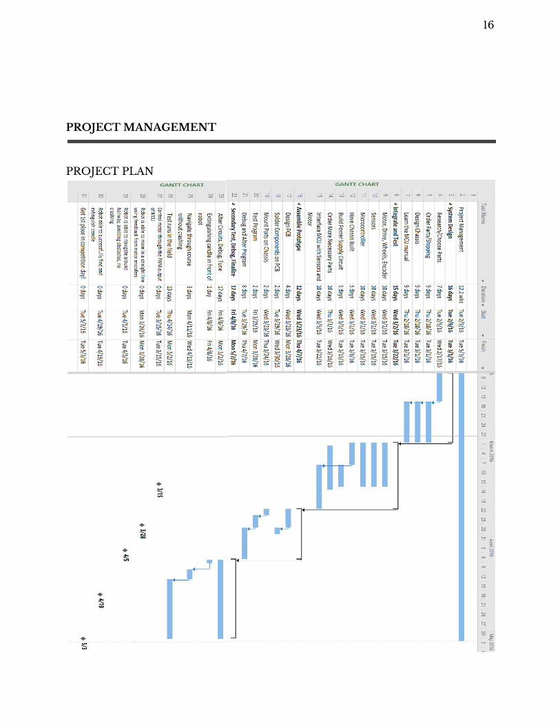
PROJECT MANAGEMENT
PROJECT PLAN
17
MILESTONES
This section explains our planned milestones for our project and provide their dates. 3/15/16: We plan on being able to integrate the motor, motor drivers, and the PIC32 microcontroller. We will be able to control the motor’s speed through the PWM output. 3/28/16: Our prototype ACE will be complete and able to move in a straight line using feedback from motor encoders. 4/5/16: ACE will be able to navigate in the hallway. The robot will be able to avoid obstacles and will not crash into a wall or obstacle. 4/19/16: ACE will be able to navigate around the course to find and extinguish the real candle. ACE should be able to save the position of the candle to decrease time of run in mode 2. 5/3/16: ACE will get 1st place in the competition with other robots! BUDGET
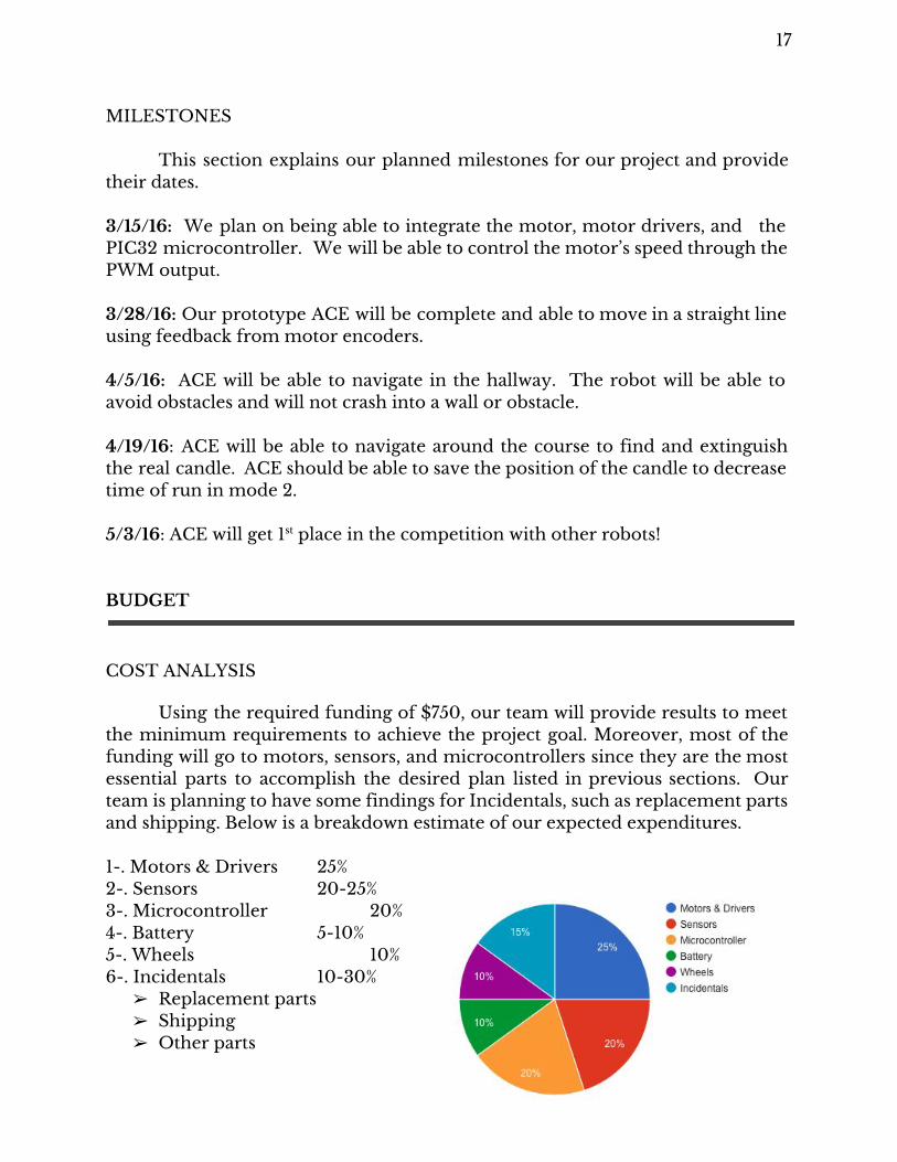
COST ANALYSIS
Using the required funding of $750, our team will provide results to meet the minimum requirements to achieve the project goal. Moreover, most of the funding will go to motors, sensors, and microcontrollers since they are the most essential parts to accomplish the desired plan listed in previous sections. Our team is planning to have some findings for Incidentals, such as replacement parts and shipping. Below is a breakdown estimate of our expected expenditures. 1-. Motors & Drivers 25% 2-. Sensors 20-25% 3-. Microcontroller 20% 4-. Battery 5-10% 5-. Wheels 10% 6-. Incidentals 10-30%
➢ Replacement parts ➢ Shipping ➢ Other parts

18
March 03, 2016
The Competition Fire “Fighting” Robots is a brand new engineering contest established at SDSU. The contest
consists of building a robot that will be able to find and extinguish the flame as quickly as
possible. Our robot is designed to meet the desired specifications and will compete against
the other SDSU fire fighting robots by the end of the semester. Our final vision is to have built
the fastest, most precise robot than the other SDSU senior design teams.
Our Team ACE is designed by a team of qualified students from
the ECE department at San Diego State University. Our
hardware team handled the fabrication of the robot,
while our software team coded the embedded systems
for our microcontroller. A vision will come to light on
May 3, 2016 when our completion unfolds.
Engineers Abukar Abdirahim Erika Serrano Dan Bernstein Ryan Torres Maryann Dalal Joseph Villanueva Cody Nnamani
Contact us: www.ace.sdsu.edu
Sponsored by:


![Legacy Fighting Championship 33 [Legacy Fighting Championship 39]](https://img.pdfslide.net/doc/110x75/55c5abb6bb61eb601f8b4749/legacy-fighting-championship-33-legacy-fighting-championship-39.jpg)