Embed Size (px)
Citation preview
Summary
A large, mostly transparent roof had to be built over the bus station at Amster-dam Central station (Fig. 1 and 2). Due to several tunnel disasters, the fire bri-gade required that if two buses with full fuel tanks were to ignite simultaneously, no glass should fall into the area below during the first 30 minutes of the ensuing fire. This new requirement had to be met without a significant increase in cost and a special glass system had to be developed. Following a theoretical study of glass subjected to fire, specific design criteria were established. Fire tests then demonstrated the ability of the design method of glass to meet the requirements without a significant increase in cost.
ing passengers’ comfort and giving the bus station an image appropriate to the new, contemporary, water-oriented Amsterdam Central.
Steel Structure
The bus roof is 360 m long and con-sists of steel arches, each with a span of over 60 m, spaced 12,5 m on centre. At the river, the arches rest on the edge of the quay, while the opposite supports are on the bus platform. The arches are linked by steel purlins, to which the roofing is fixed. Most of the roof is transparent and uses cold bendable laminated glass.
Glass System
A laminated glass system is used, in which the panes are cold-formed on site using a patented process [1], [2]. The use of cold bendable laminated glass makes it possible to use curved supporting structures throughout.
This avoids segmenting the support-ing structures, by minimizing the num-ber of connectors and hence reducing costs. In addition, cold bendable lami-nated glass is less expensive than hot bendable. Because of these savings, the roof is only around 50% of expected costs.
The panes consist of a 5 mm tem-pered sheet below, with a 4 mm heat-strengthened sheet on top. A plastic film joins the two sheets. The lower sheet is toughened so that it is possible to walk on the glass. Each pane is 3,1 m long and 1,1 m wide. The long sides of each pane are secured to a continuous rolled I-section using an aluminium retaining strip. Stainless steel C-sec-tions are glued to the short edges of the panes in the factory. This allows the glass to be supported on four sides, without the need to fit separate components during construction.
Fire Safety Requirement
Fire Brigade Requirements
Naturally, the structure meets normal fire safety requirements. The future public transport interchange, of which the bus station with its roof forms a part, is so complex on account of its size and its links with other parts of the project that normal fire safety specifications would not be sufficient. The fire brigade therefore formulated specific requirements. These set out the acceptable conditions on the bus plat-
Fire Resistant Roof Glazing Design László Vákár, Head of Structural Design, Eric Kool, Senior Advisor Structural Design, Jan van Wolfswinkel, Advisor Structural Design, Movares, Utrecht, The Netherlands
Introduction
A new design requirement for the bus station roof was added in the middle of the design phase. As less time was avail-able for extensive research, a practical solution was developed with the use of cold bendable laminated glass al-ready selected for the roof. The chosen method is an analysis of the fire behav-iour of the glass and identification of possible causes of fracture. Taking the above as a basis, the glass system had to be detailed such that it could meet the 30 minutes requirement. Full-scale fire tests should validate the effective-ness of the performance-based design of the glass system developed, and hence the provision of the safety level demanded.
Bus Station Roof Bus Station
The roof, which covers a bus platform, is a part of Amsterdam’s IJ river proj-ect. Amsterdam Central is one of the largest public transport interchanges in the Netherlands. The platform will be located between the river IJ and the existing railway station. The roof will cover the entire platform, thus provid-
Peer-reviewed by international ex-perts and accepted for publication by SEI Editorial Board
Paper received: December 6, 2005Paper accepted: January 30, 2006
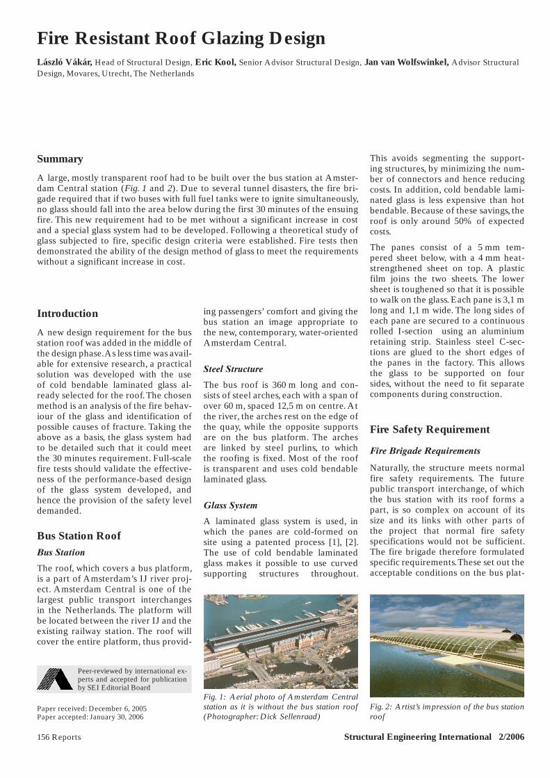
Fig. 1: Aerial photo of Amsterdam Central station as it is without the bus station roof (Photographer: Dick Sellenraad)
Fig. 2: Artist’s impression of the bus station roof
156 Reports Structural Engineering International 2/2006
Report X-143.indd 1Report X-143.indd 1 3/27/06 7:57:47 PM3/27/06 7:57:47 PM
form during a fire on the one hand, and the fire resistance of the structure and its ability to prevent glass from falling down into the area below on the other. These requirements are intended to ensure that passengers can escape and that fire fighting and rescue operations can be carried out safely.
Type of Fire
The fire brigade specified the type of fire to be considered: the fuel tanks of two buses ignite at the same time and in the same place, both tanks are full and the buses provide no protec-tion against the effects of the fire, the combat of the fire being neglected. All involved parties, including the fire bri-gade, consider this a very exceptional event.
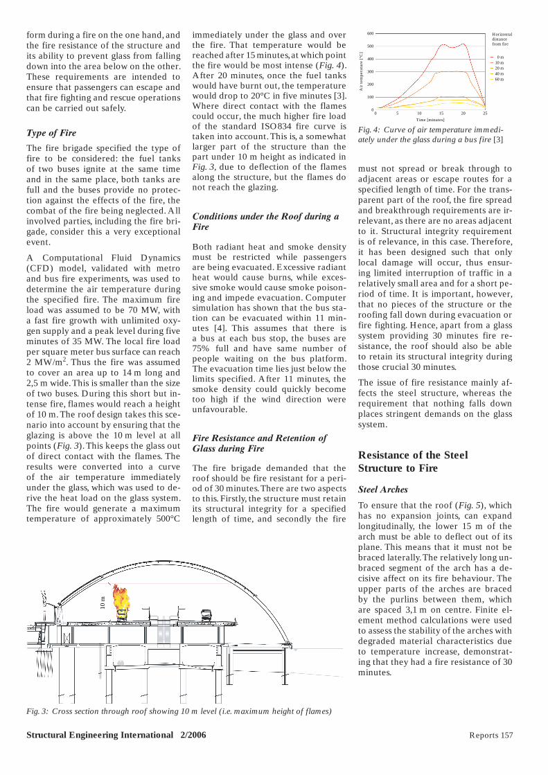
A Computational Fluid Dynamics (CFD) model, validated with metro and bus fire experiments, was used to determine the air temperature during the specified fire. The maximum fire load was assumed to be 70 MW, with a fast fire growth with unlimited oxy-gen supply and a peak level during five minutes of 35 MW. The local fire load per square meter bus surface can reach 2 MW/m2. Thus the fire was assumed to cover an area up to 14 m long and 2,5 m wide. This is smaller than the size of two buses. During this short but in-tense fire, flames would reach a height of 10 m. The roof design takes this sce-nario into account by ensuring that the glazing is above the 10 m level at all points (Fig. 3). This keeps the glass out of direct contact with the flames. The results were converted into a curve of the air temperature immediately under the glass, which was used to de-rive the heat load on the glass system. The fire would generate a maximum temperature of approximately 500°C
immediately under the glass and over the fire. That temperature would be reached after 15 minutes, at which point the fire would be most intense (Fig. 4). After 20 minutes, once the fuel tanks would have burnt out, the temperature would drop to 20°C in five minutes [3]. Where direct contact with the flames could occur, the much higher fire load of the standard ISO834 fire curve is taken into account. This is, a somewhat larger part of the structure than the part under 10 m height as indicated in Fig. 3, due to deflection of the flames along the structure, but the flames do not reach the glazing.
Conditions under the Roof during a Fire
Both radiant heat and smoke density must be restricted while passengers are being evacuated. Excessive radiant heat would cause burns, while exces-sive smoke would cause smoke poison-ing and impede evacuation. Computer simulation has shown that the bus sta-tion can be evacuated within 11 min-utes [4]. This assumes that there is a bus at each bus stop, the buses are 75% full and have same number of people waiting on the bus platform. The evacuation time lies just below the limits specified. After 11 minutes, the smoke density could quickly become too high if the wind direction were unfavourable.
Fire Resistance and Retention of Glass during Fire
The fire brigade demanded that the roof should be fire resistant for a peri-od of 30 minutes. There are two aspects to this. Firstly, the structure must retain its structural integrity for a specified length of time, and secondly the fire
must not spread or break through to adjacent areas or escape routes for a specified length of time. For the trans-parent part of the roof, the fire spread and breakthrough requirements are ir-relevant, as there are no areas adjacent to it. Structural integrity requirement is of relevance, in this case. Therefore, it has been designed such that only local damage will occur, thus ensur-ing limited interruption of traffic in a relatively small area and for a short pe-riod of time. It is important, however, that no pieces of the structure or the roofing fall down during evacuation or fire fighting. Hence, apart from a glass system providing 30 minutes fire re-sistance, the roof should also be able to retain its structural integrity during those crucial 30 minutes.
The issue of fire resistance mainly af-fects the steel structure, whereas the requirement that nothing falls down places stringent demands on the glass system.
Resistance of the Steel Structure to Fire
Steel Arches
To ensure that the roof (Fig. 5), which has no expansion joints, can expand longitudinally, the lower 15 m of the arch must be able to deflect out of its plane. This means that it must not be braced laterally. The relatively long un-braced segment of the arch has a de-cisive affect on its fire behaviour. The upper parts of the arches are braced by the purlins between them, which are spaced 3,1 m on centre. Finite el-ement method calculations were used to assess the stability of the arches with degraded material characteristics due to temperature increase, demonstrat-ing that they had a fire resistance of 30 minutes.
Structural Engineering International 2/2006 Reports 157
10 m
Fig. 3: Cross section through roof showing 10 m level (i.e. maximum height of flames)
600
500
400
300
200
100
00 5 10 15 20 25
Horizontaldistancefrom fire
0 m10 m20 m40 m60 m
Air
tem
pera
ture
[°C
]
Time [minutes]
Fig. 4: Curve of air temperature immedi-ately under the glass during a bus fire [3]
Report X-143.indd 2Report X-143.indd 2 3/27/06 7:57:57 PM3/27/06 7:57:57 PM
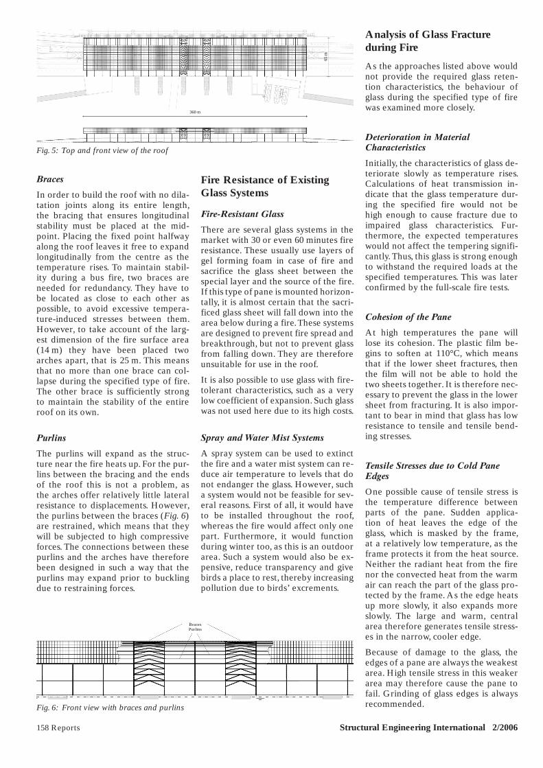
Braces
In order to build the roof with no dila-tation joints along its entire length, the bracing that ensures longitudinal stability must be placed at the mid-point. Placing the fixed point halfway along the roof leaves it free to expand longitudinally from the centre as the temperature rises. To maintain stabil-ity during a bus fire, two braces are needed for redundancy. They have to be located as close to each other as possible, to avoid excessive tempera-ture-induced stresses between them. However, to take account of the larg-est dimension of the fire surface area (14 m) they have been placed two arches apart, that is 25 m. This means that no more than one brace can col-lapse during the specified type of fire. The other brace is sufficiently strong to maintain the stability of the entire roof on its own.
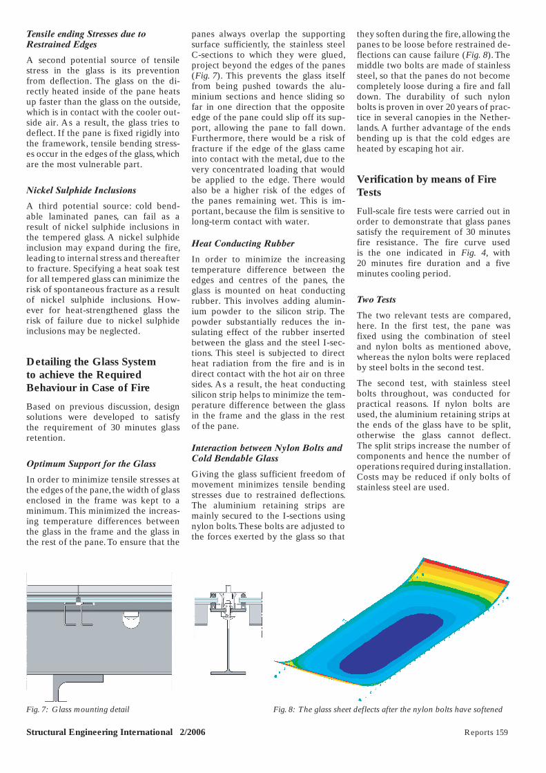
Purlins
The purlins will expand as the struc-ture near the fire heats up. For the pur-lins between the bracing and the ends of the roof this is not a problem, as the arches offer relatively little lateral resistance to displacements. However, the purlins between the braces (Fig. 6) are restrained, which means that they will be subjected to high compressive forces. The connections between these purlins and the arches have therefore been designed in such a way that the purlins may expand prior to buckling due to restraining forces.
Fire Resistance of Existing Glass Systems
Fire-Resistant Glass
There are several glass systems in the market with 30 or even 60 minutes fire resistance. These usually use layers of gel forming foam in case of fire and sacrifice the glass sheet between the special layer and the source of the fire. If this type of pane is mounted horizon-tally, it is almost certain that the sacri-ficed glass sheet will fall down into the area below during a fire. These systems are designed to prevent fire spread and breakthrough, but not to prevent glass from falling down. They are therefore unsuitable for use in the roof.
It is also possible to use glass with fire-tolerant characteristics, such as a very low coefficient of expansion. Such glass was not used here due to its high costs.
Spray and Water Mist Systems
A spray system can be used to extinct the fire and a water mist system can re-duce air temperature to levels that do not endanger the glass. However, such a system would not be feasible for sev-eral reasons. First of all, it would have to be installed throughout the roof, whereas the fire would affect only one part. Furthermore, it would function during winter too, as this is an outdoor area. Such a system would also be ex-pensive, reduce transparency and give birds a place to rest, thereby increasing pollution due to birds’ excrements.
Analysis of Glass Fracture during Fire
As the approaches listed above would not provide the required glass reten-tion characteristics, the behaviour of glass during the specified type of fire was examined more closely.
Deterioration in Material Characteristics
Initially, the characteristics of glass de-teriorate slowly as temperature rises. Calculations of heat transmission in-dicate that the glass temperature dur-ing the specified fire would not be high enough to cause fracture due to impaired glass characteristics. Fur-thermore, the expected temperatures would not affect the tempering signifi-cantly. Thus, this glass is strong enough to withstand the required loads at the specified temperatures. This was later confirmed by the full-scale fire tests.
Cohesion of the Pane
At high temperatures the pane will lose its cohesion. The plastic film be-gins to soften at 110°C, which means that if the lower sheet fractures, then the film will not be able to hold the two sheets together. It is therefore nec-essary to prevent the glass in the lower sheet from fracturing. It is also impor-tant to bear in mind that glass has low resistance to tensile and tensile bend-ing stresses.
Tensile Stresses due to Cold Pane Edges
One possible cause of tensile stress is the temperature difference between parts of the pane. Sudden applica-tion of heat leaves the edge of the glass, which is masked by the frame, at a relatively low temperature, as the frame protects it from the heat source. Neither the radiant heat from the fire nor the convected heat from the warm air can reach the part of the glass pro-tected by the frame. As the edge heats up more slowly, it also expands more slowly. The large and warm, central area therefore generates tensile stress-es in the narrow, cooler edge.
Because of damage to the glass, the edges of a pane are always the weakest area. High tensile stress in this weaker area may therefore cause the pane to fail. Grinding of glass edges is always recommended.
158 Reports Structural Engineering International 2/2006
360 m
65 m
Fig. 5: Top and front view of the roof
BracesPurlins
Fig. 6: Front view with braces and purlins
Report X-143.indd 3Report X-143.indd 3 3/27/06 7:58:03 PM3/27/06 7:58:03 PM
Tensile ending Stresses due to Restrained Edges
A second potential source of tensile stress in the glass is its prevention from deflection. The glass on the di-rectly heated inside of the pane heats up faster than the glass on the outside, which is in contact with the cooler out-side air. As a result, the glass tries to deflect. If the pane is fixed rigidly into the framework, tensile bending stress-es occur in the edges of the glass, which are the most vulnerable part.
Nickel Sulphide Inclusions
A third potential source: cold bend-able laminated panes, can fail as a result of nickel sulphide inclusions in the tempered glass. A nickel sulphide inclusion may expand during the fire, leading to internal stress and thereafter to fracture. Specifying a heat soak test for all tempered glass can minimize the risk of spontaneous fracture as a result of nickel sulphide inclusions. How-ever for heat-strengthened glass the risk of failure due to nickel sulphide inclusions may be neglected.
Detailing the Glass System to achieve the Required Behaviour in Case of Fire
Based on previous discussion, design solutions were developed to satisfy the requirement of 30 minutes glass retention.
Optimum Support for the Glass
In order to minimize tensile stresses at the edges of the pane, the width of glass enclosed in the frame was kept to a minimum. This minimized the increas-ing temperature differences between the glass in the frame and the glass in the rest of the pane. To ensure that the
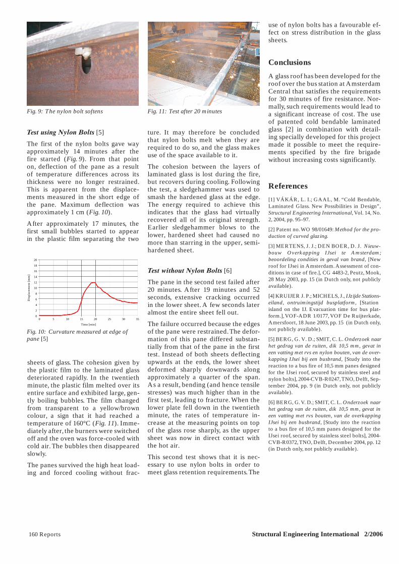
panes always overlap the supporting surface sufficiently, the stainless steel C-sections to which they were glued, project beyond the edges of the panes (Fig. 7). This prevents the glass itself from being pushed towards the alu-minium sections and hence sliding so far in one direction that the opposite edge of the pane could slip off its sup-port, allowing the pane to fall down. Furthermore, there would be a risk of fracture if the edge of the glass came into contact with the metal, due to the very concentrated loading that would be applied to the edge. There would also be a higher risk of the edges of the panes remaining wet. This is im-portant, because the film is sensitive to long-term contact with water.
Heat Conducting Rubber
In order to minimize the increasing temperature difference between the edges and centres of the panes, the glass is mounted on heat conducting rubber. This involves adding alumin-ium powder to the silicon strip. The powder substantially reduces the in-sulating effect of the rubber inserted between the glass and the steel I-sec-tions. This steel is subjected to direct heat radiation from the fire and is in direct contact with the hot air on three sides. As a result, the heat conducting silicon strip helps to minimize the tem-perature difference between the glass in the frame and the glass in the rest of the pane.
Interaction between Nylon Bolts and Cold Bendable Glass
Giving the glass sufficient freedom of movement minimizes tensile bending stresses due to restrained deflections. The aluminium retaining strips are mainly secured to the I-sections using nylon bolts. These bolts are adjusted to the forces exerted by the glass so that
they soften during the fire, allowing the panes to be loose before restrained de-flections can cause failure (Fig. 8). The middle two bolts are made of stainless steel, so that the panes do not become completely loose during a fire and fall down. The durability of such nylon bolts is proven in over 20 years of prac-tice in several canopies in the Nether-lands. A further advantage of the ends bending up is that the cold edges are heated by escaping hot air.
Verification by means of Fire Tests
Full-scale fire tests were carried out in order to demonstrate that glass panes satisfy the requirement of 30 minutes fire resistance. The fire curve used is the one indicated in Fig. 4, with 20 minutes fire duration and a fiveminutes cooling period.
Two Tests
The two relevant tests are compared, here. In the first test, the pane was fixed using the combination of steel and nylon bolts as mentioned above, whereas the nylon bolts were replaced by steel bolts in the second test.
The second test, with stainless steel bolts throughout, was conducted for practical reasons. If nylon bolts are used, the aluminium retaining strips at the ends of the glass have to be split, otherwise the glass cannot deflect. The split strips increase the number of components and hence the number of operations required during installation. Costs may be reduced if only bolts of stainless steel are used.
Structural Engineering International 2/2006 Reports 159
Fig. 7: Glass mounting detail Fig. 8: The glass sheet deflects after the nylon bolts have softened
Report X-143.indd 4Report X-143.indd 4 3/27/06 7:58:06 PM3/27/06 7:58:06 PM
160 Reports Structural Engineering International 2/2006
Test using Nylon Bolts [5]
The first of the nylon bolts gave way approximately 14 minutes after the fire started (Fig. 9). From that point on, deflection of the pane as a result of temperature differences across its thickness were no longer restrained. This is apparent from the displace-ments measured in the short edge of the pane. Maximum deflection was approximately 1 cm (Fig. 10).
After approximately 17 minutes, the first small bubbles started to appear in the plastic film separating the two
ture. It may therefore be concluded that nylon bolts melt when they are required to do so, and the glass makes use of the space available to it.
The cohesion between the layers of laminated glass is lost during the fire, but recovers during cooling. Following the test, a sledgehammer was used to smash the hardened glass at the edge. The energy required to achieve this indicates that the glass had virtually recovered all of its original strength. Earlier sledgehammer blows to the lower, hardened sheet had caused no more than starring in the upper, semi-hardened sheet.
Test without Nylon Bolts [6]
The pane in the second test failed after 20 minutes. After 19 minutes and 52 seconds, extensive cracking occurred in the lower sheet. A few seconds later almost the entire sheet fell out.
The failure occurred because the edges of the pane were restrained. The defor-mation of this pane differed substan-tially from that of the pane in the first test. Instead of both sheets deflecting upwards at the ends, the lower sheet deformed sharply downwards along approximately a quarter of the span. As a result, bending (and hence tensile stresses) was much higher than in the first test, leading to fracture. When the lower plate fell down in the twentieth minute, the rates of temperature in-crease at the measuring points on top of the glass rose sharply, as the upper sheet was now in direct contact with the hot air.
This second test shows that it is nec-essary to use nylon bolts in order to meet glass retention requirements. The
use of nylon bolts has a favourable ef-fect on stress distribution in the glass sheets.
Conclusions
A glass roof has been developed for the roof over the bus station at Amsterdam Central that satisfies the requirements for 30 minutes of fire resistance. Nor-mally, such requirements would lead to a significant increase of cost. The use of patented cold bendable laminated glass [2] in combination with detail-ing specially developed for this project made it possible to meet the require-ments specified by the fire brigade without increasing costs significantly.
References
[1] VÁKÁR, L. I.; GAAL, M. “Cold Bendable, Laminated Glass. New Possibilities in Design”, Structural Engineering International, Vol. 14, No. 2, 2004, pp. 95–97.
[2] Patent no. WO 98/01649: Method for the pro-duction of curved glazing.
[3] MERTENS, J. J.; DEN BOER, D. J. Nieuw-bouw Overkapping IJsei te Amsterdam; beoordeling condities in geval van brand, [New roof for IJsei in Amsterdam. Assessment of con-ditions in case of fire.], CG 4483-2, Peutz, Mook, 28 May 2003, pp. 15 (in Dutch only, not publicly available).
[4] KRUIJER J. P.; MICHELS, J., IJzijde Stations-eiland, ontruimingstijd busplatform, [Station island on the IJ. Evacuation time for bus plat-form.], VOF-ADR 1/0177, VOF De Ruijterkade, Amersfoort, 18 June 2003, pp. 15 (in Dutch only, not publicly available).
[5] BERG, G. V. D.; SMIT, C. L. Onderzoek naar het gedrag van de ruiten, dik 10,5 mm, gevat in een vatting met rvs en nylon bouten, van de over-kapping IJsei bij een busbrand, [Study into the reaction to a bus fire of 10,5 mm panes designed for the IJsei roof, secured by stainless steel and nylon bolts], 2004-CVB-R0247, TNO, Delft, Sep-tember 2004, pp. 9 (in Dutch only, not publicly available).
[6] BERG, G. V. D.; SMIT, C. L. Onderzoek naar het gedrag van de ruiten, dik 10,5 mm, gevat in een vatting met rvs bouten, van de overkapping IJsei bij een busbrand, [Study into the reaction to a bus fire of 10,5 mm panes designed for the IJsei roof, secured by stainless steel bolts], 2004-CVB-R0372, TNO, Delft, December 2004, pp. 12 (in Dutch only, not publicly available).
Fig. 9: The nylon bolt softens
20
18
16
14
12
10
8
6
4
2
00 5 10 15 20 25 30 35
Time [min]
Dis
plac
emen
t [m
m]
Fig. 10: Curvature measured at edge of pane [5]
Fig. 11: Test after 20 minutes
sheets of glass. The cohesion given by the plastic film to the laminated glass deteriorated rapidly. In the twentieth minute, the plastic film melted over its entire surface and exhibited large, gen-tly boiling bubbles. The film changed from transparent to a yellow/brown colour, a sign that it had reached a temperature of 160°C (Fig. 11). Imme-diately after, the burners were switched off and the oven was force-cooled with cold air. The bubbles then disappeared slowly.
The panes survived the high heat load-ing and forced cooling without frac-
Report X-143.indd 5Report X-143.indd 5 3/27/06 7:58:13 PM3/27/06 7:58:13 PM


![[THESIS PROPOSAL] - Penn State College of Engineering. Design the blast resistant glass façade using “Blast‐Resistant Glazing Design” by H. Scott Norville & Edward Conrath in](https://img.pdfslide.net/doc/110x75/5ad8019b7f8b9a9d5c8cc819/thesis-proposal-penn-state-college-of-engineering-design-the-blast-resistant.jpg)