Embed Size (px)
Citation preview
A product of SEGGER Microcontroller GmbH & Co. KG
www.segger.com
Flasher ARM
Manual Rev. 24
User guide of the stand-alone JTAG/SWD programmer for ARM Cores
Document: UM08007
Date: October 19, 2012
2
Disclaimer
Specifications written in this document are believed to be accurate, but are not guar-anteed to be entirely free of error. The information in this manual is subject tochange for functional or performance improvements without notice. Please make sureyour manual is the latest edition. While the information herein is assumed to beaccurate, SEGGER Microcontroller GmbH & Co. KG (the manufacturer) assumes noresponsibility for any errors or omissions. The manufacturer makes and you receiveno warranties or conditions, express, implied, statutory or in any communication withyou. The manufacturer specifically disclaims any implied warranty of merchantabilityor fitness for a particular purpose.
Copyright notice
You may not extract portions of this manual or modify the PDF file in any way withoutthe prior written permission of the manufacturer. The software described in this doc-ument is furnished under a license and may only be used or copied in accordancewith the terms of such a license.
© 2012 SEGGER Microcontroller GmbH & Co. KG, Hilden / Germany
Trademarks
Names mentioned in this manual may be trademarks of their respective companies.
Brand and product names are trademarks or registered trademarks of their respec-tive holders.
Contact address
SEGGER Microcontroller GmbH & Co. KG
In den Weiden 11D-40721 Hilden
Germany
Tel.+49 2103-2878-0Fax.+49 2103-2878-28Email: [email protected]: http://www.segger.com
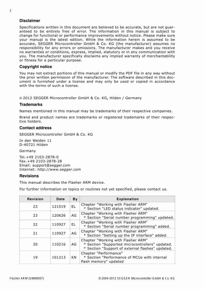
Revisions
This manual describes the Flasher ARM device.
For further information on topics or routines not yet specified, please contact us.
Revision Date By Explanation
23 121019 EL Chapter "Working with Flasher ARM" * Section "LED status indicator" updated.
23 120626 AG Chapter "Working with Flasher ARM" * Section "Serial number programming" updated.
22 110927 EL Chapter "Working with Flasher ARM" * Section "Serial number programming" added.
21 110927 AG Chapter "Working with Flasher ARM" * Section "Setting up the IP interface" added.
20 110216 AGChapter "Working with Flasher ARM" * Section "Supported microcontrollers" updated. * Section "Support of external flashes" updated.
19 101213 KNChapter "Performance" * Section "Performance of MCUs with internal flash memory" updated
Flasher ARM (UM08007) © 2004-2012 SEGGER Microcontroller GmbH & Co. KG
3
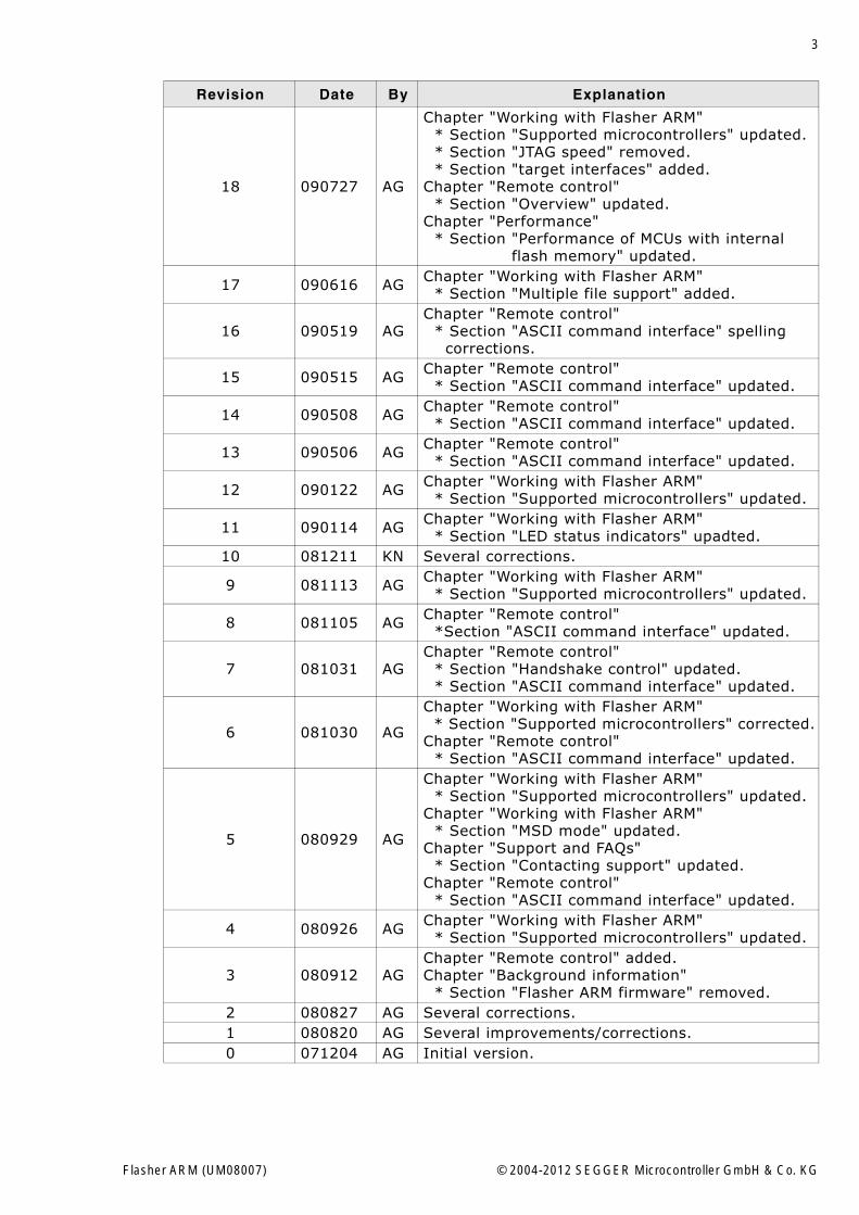
18 090727 AG
Chapter "Working with Flasher ARM" * Section "Supported microcontrollers" updated. * Section "JTAG speed" removed. * Section "target interfaces" added.Chapter "Remote control" * Section "Overview" updated.Chapter "Performance" * Section "Performance of MCUs with internal flash memory" updated.
17 090616 AG Chapter "Working with Flasher ARM" * Section "Multiple file support" added.
16 090519 AGChapter "Remote control" * Section "ASCII command interface" spelling corrections.
15 090515 AG Chapter "Remote control" * Section "ASCII command interface" updated.
14 090508 AG Chapter "Remote control" * Section "ASCII command interface" updated.
13 090506 AG Chapter "Remote control" * Section "ASCII command interface" updated.
12 090122 AG Chapter "Working with Flasher ARM" * Section "Supported microcontrollers" updated.
11 090114 AG Chapter "Working with Flasher ARM" * Section "LED status indicators" upadted.
10 081211 KN Several corrections.
9 081113 AG Chapter "Working with Flasher ARM" * Section "Supported microcontrollers" updated.
8 081105 AG Chapter "Remote control" *Section "ASCII command interface" updated.
7 081031 AGChapter "Remote control" * Section "Handshake control" updated. * Section "ASCII command interface" updated.
6 081030 AG
Chapter "Working with Flasher ARM" * Section "Supported microcontrollers" corrected.Chapter "Remote control" * Section "ASCII command interface" updated.
5 080929 AG
Chapter "Working with Flasher ARM" * Section "Supported microcontrollers" updated.Chapter "Working with Flasher ARM" * Section "MSD mode" updated.Chapter "Support and FAQs" * Section "Contacting support" updated.Chapter "Remote control" * Section "ASCII command interface" updated.
4 080926 AG Chapter "Working with Flasher ARM" * Section "Supported microcontrollers" updated.
3 080912 AGChapter "Remote control" added.Chapter "Background information" * Section "Flasher ARM firmware" removed.
2 080827 AG Several corrections.1 080820 AG Several improvements/corrections.0 071204 AG Initial version.
Revision Date By Explanation
Flasher ARM (UM08007) © 2004-2012 SEGGER Microcontroller GmbH & Co. KG

4
Flasher ARM (UM08007) © 2004-2012 SEGGER Microcontroller GmbH & Co. KG
5
About this document
This document describes the Flasher ARM. It provides an overview over the majorfeatures of the Flasher ARM, gives you some background information about JTAG,ARM general and describes Flasher ARM related software packages available fromSegger. Finally, the chapter Support and FAQs on page 53 helps to troubleshoot com-mon problems.
Typographic conventions
This manual uses the following typographic conventions:
Style Used for
Body Body text.
KeywordText that you enter at the command-prompt or that appears on the display (that is system functions, file- or pathnames).
Reference Reference to chapters, tables and figures or other documents.
GUIElement Buttons, dialog boxes, menu names, menu commands.
Table 1.1: Typographic conventions
Flasher ARM (UM08007) © 2004-2012 SEGGER Microcontroller GmbH & Co. KG
6
EMBEDDED SOFTWARE(Middleware)
emWinGraphics software and GUIemWin is designed to provide an effi-cient, processor- and display control-ler-independent graphical user interface (GUI) for any application that operates with a graphical display. Starterkits, eval- and trial-versions are available.
embOSReal Time Operating SystemembOS is an RTOS designed to offer the benefits of a complete multitasking system for hard real time applications with minimal resources. The profiling PC tool embOSView is included.
emFileFile systememFile is an embedded file system with FAT12, FAT16 and FAT32 support. emFile has been optimized for mini-mum memory consumption in RAM and ROM while maintaining high speed. Various Device drivers, e.g. for NAND and NOR flashes, SD/MMC and Com-pactFlash cards, are available.
emUSBUSB device stackA USB stack designed to work on any embedded system with a USB client controller. Bulk communication and most standard device classes are sup-ported.
SEGGER TOOLS
Flasher Flash programmerFlash Programming tool primarily for microcon-trollers.
J-LinkJTAG emulator for ARM coresUSB driven JTAG interface for ARM cores.
J-TraceJTAG emulator with traceUSB driven JTAG interface for ARM cores with Trace memory. supporting the ARM ETM (Embed-ded Trace Macrocell).
J-Link / J-Trace Related SoftwareAdd-on software to be used with SEGGER�s indus-try standard JTAG emulator, this includes flash programming software and flash breakpoints.
SEGGER Microcontroller GmbH & Co. KG developsand distributes software development tools and ANSIC software components (middleware) for embeddedsystems in several industries such as telecom, medi-cal technology, consumer electronics, automotiveindustry and industrial automation.
SEGGER�s intention is to cut software development-time for embedded applications by offering compact flexible and easy to use middleware,allowing developers to concentrate on their application.
Our most popular products are emWin, a universal graphic software package for embed-ded applications, and embOS, a small yet efficient real-time kernel. emWin, writtenentirely in ANSI C, can easily be used on any CPU and most any display. It is comple-mented by the available PC tools: Bitmap Converter, Font Converter, Simulator andViewer. embOS supports most 8/16/32-bit CPUs. Its small memory footprint makes itsuitable for single-chip applications.
Apart from its main focus on software tools, SEGGER develops and produces programmingtools for flash microcontrollers, as well as J-Link, a JTAG emulator to assist in develop-ment, debugging and production, which has rapidly become the industry standard fordebug access to ARM cores.
Corporate Office:http://www.segger.com
United States Office:http://www.segger-us.com
Flasher ARM (UM08007) © 2004-2012 SEGGER Microcontroller GmbH & Co. KG
7
Table of Contents
1 Introduction ......................................................................................................................9
1.1 Flasher ARM overview ..............................................................................101.1.1 Features of Flasher ARM ...........................................................................101.1.2 Working environment...............................................................................101.2 Specifications..........................................................................................111.2.1 Specifications for Flasher ARM ...................................................................111.2.2 Flasher ARM Download speed ....................................................................11
2 Working with Flasher ARM ............................................................................................13
2.1 Setting up the IP interface ........................................................................142.1.1 Connecting the first time ..........................................................................142.2 Operating modes .....................................................................................152.2.1 J-Link mode............................................................................................152.2.2 Stand-alone mode ...................................................................................192.2.3 MSD mode..............................................................................................192.3 Multiple File Support ................................................................................212.4 Serial number programming......................................................................222.4.1 Serial number settings .............................................................................222.4.2 Serial number file ....................................................................................232.4.3 Serial number list file ...............................................................................232.4.4 Programming process...............................................................................242.4.5 Downloading serial number files to Flasher ARM...........................................252.4.6 Sample setup..........................................................................................252.5 Target interfaces .....................................................................................272.6 Supported microcontrollers .......................................................................282.7 Support of external flashes .......................................................................292.8 Supported ARM Cores ..............................................................................30
3 Remote control...............................................................................................................31
3.1 Overview................................................................................................323.2 Handshake control ...................................................................................333.3 ASCII command interface .........................................................................343.3.1 Introduction............................................................................................343.3.2 General command and reply message format ..............................................343.3.3 Communication port settings.....................................................................343.3.4 Commands to Flasher...............................................................................343.3.5 Reply from Flasher ARM............................................................................38
4 Performance ..................................................................................................................41
4.1 Performance of MCUs with internal flash memory.........................................42
5 Hardware .......................................................................................................................43
5.1 JTAG Connector.......................................................................................445.1.1 Pinout ....................................................................................................445.1.2 Target board design for JTAG ....................................................................455.1.3 Target power supply ................................................................................455.2 Using the JTAG connector with SWD...........................................................465.2.1 Pin Out...................................................................................................465.3 RESET, nTRST.........................................................................................47
Flasher ARM (UM08007) © 2004-2012 SEGGER Microcontroller GmbH & Co. KG
8
5.4 Adapters ................................................................................................ 485.4.1 J-Link JTAG Isolator................................................................................. 485.4.2 Pinout.................................................................................................... 485.5 How to determine the hardware version ..................................................... 49
6 Background information .................................................................................................51
6.1 Flash programming ................................................................................. 526.1.1 How does flash programming via Flasher ARM work ?................................... 526.1.2 Data download to RAM............................................................................. 526.1.3 Available options for flash programming ..................................................... 52
7 Support and FAQs .........................................................................................................53
7.1 Contacting support .................................................................................. 547.2 Frequently Asked Questions...................................................................... 55
8 Glossary.........................................................................................................................57
9 Literature and references...............................................................................................61
Flasher ARM (UM08007) © 2004-2012 SEGGER Microcontroller GmbH & Co. KG
9
Chapter 1
Introduction
This chapter gives a short overview about the Flasher ARM.
Flasher ARM (UM08007) © 2004-2012 SEGGER Microcontroller GmbH & Co. KG
10 CHAPTER 1 Introduction
1.1 Flasher ARM overviewFlasher ARM is a programming tool for microcontrollers with on-chip or external Flashmemory and ARM core. Flasher ARM is designed for programming flash targets withthe J-Flash software or stand-alone. In addition to that Flasher ARM has all of the J-Link functionality. For more information about J-Link please refer to the J-Link / J-Trace User Guide which can be downloaded at http://www.segger.com.Flasher ARM connects via USB or via RS232 interface to a PC, running Microsoft Win-dows 2000, Windows XP, Windows 2003 or Windows Vista. Flasher ARM has a built-in20-pin JTAG connector, which is compatible with the standard 20-pin connectordefined by ARM.
1.1.1 Features of Flasher ARM� Three boot modes: J-Link mode, stand-alone mode, MSD mode� Stand-alone JTAG programmer (Once set up, Flasher can be controlled without
the use of PC program)� No power supply required, powered through USB� Support for ARM7/ARM9/Cortex-M3� Supports internal and external flash devices � 64 MB memory for storage of target program� Can be used as J-Link (JTAG emulator) with a download speed of up to 720
Kbytes/second� Programming speed between 30-300 Kbytes/second depending on target hard-
ware� Serial in target programming supported� Data files can updated via J-Flash� Target interface: JTAG/SWD
1.1.2 Working environmentGeneral
Flasher ARM can be operated from a PC with an appropriate software like J-Flash orin stand-alone mode.
Host System
IBM PC/AT or compatible. CPU: 486 (or better) with at least 182MB of RAM, runningMicrosoft Windows 2000, Windows XP, Windows 2003 or Windows Vista. It needs tohave an USB or RS232 interface available for communication with Flasher ARM.
Power supply
Flasher requires 5V DC, min. 100mA via USB connector. If USB is not connected, theUSB connector is used to power the device. Supply voltage is the same in this case.Please avoid excess voltage.
Installing Flasher ARM PC-software J-Flash
The latest version of the J-Flash software, which is part of the J-Link software anddocumentation package, can be downloaded from our website: http://www.seg-ger.com. For more information about using J-Flash please refer to the J-Flash UserGuide which is also available for download on our website.
Flasher ARM (UM08007) © 2004-2012 SEGGER Microcontroller GmbH & Co. KG
11
1.2 Specifications
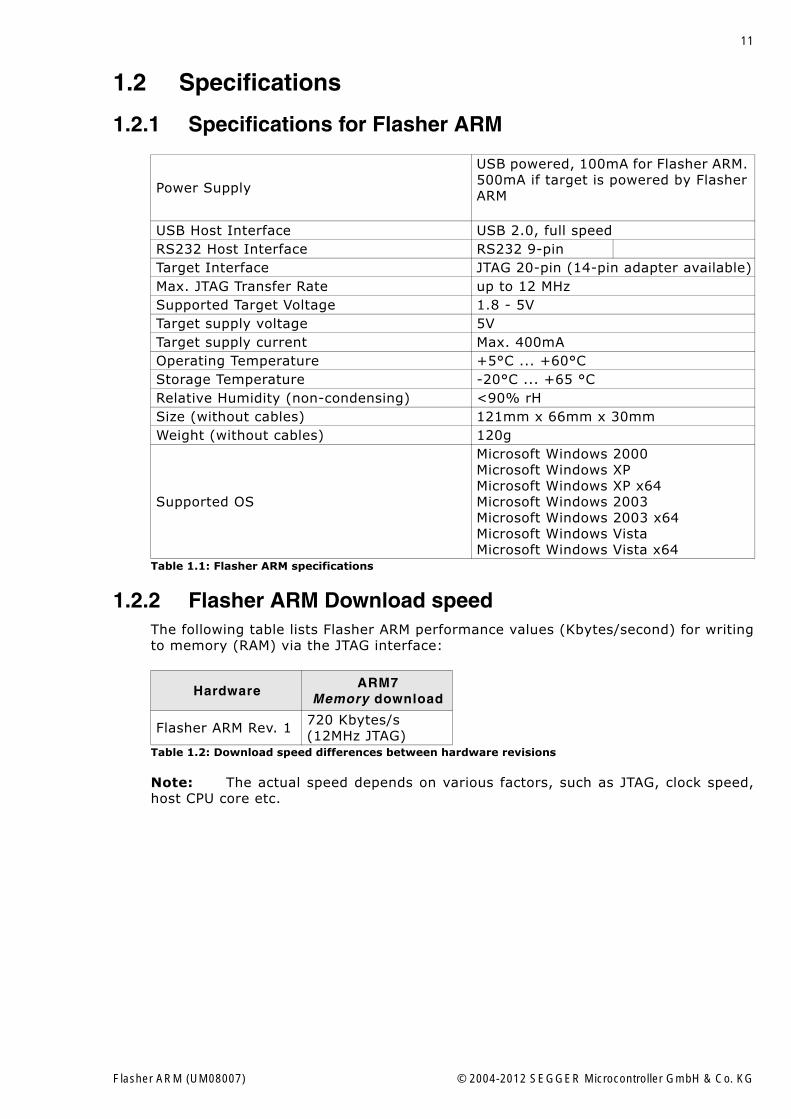
1.2.1 Specifications for Flasher ARM
1.2.2 Flasher ARM Download speedThe following table lists Flasher ARM performance values (Kbytes/second) for writingto memory (RAM) via the JTAG interface:
Note: The actual speed depends on various factors, such as JTAG, clock speed,host CPU core etc.
Power Supply
USB powered, 100mA for Flasher ARM. 500mA if target is powered by Flasher ARM
USB Host Interface USB 2.0, full speedRS232 Host Interface RS232 9-pinTarget Interface JTAG 20-pin (14-pin adapter available)Max. JTAG Transfer Rate up to 12 MHzSupported Target Voltage 1.8 - 5VTarget supply voltage 5VTarget supply current Max. 400mAOperating Temperature +5°C ... +60°CStorage Temperature -20°C ... +65 °CRelative Humidity (non-condensing) <90% rHSize (without cables) 121mm x 66mm x 30mmWeight (without cables) 120g
Supported OS
Microsoft Windows 2000Microsoft Windows XPMicrosoft Windows XP x64Microsoft Windows 2003Microsoft Windows 2003 x64Microsoft Windows VistaMicrosoft Windows Vista x64
Table 1.1: Flasher ARM specifications
HardwareARM7
Memory download
Flasher ARM Rev. 1 720 Kbytes/s (12MHz JTAG)
Table 1.2: Download speed differences between hardware revisions
Flasher ARM (UM08007) © 2004-2012 SEGGER Microcontroller GmbH & Co. KG
12 CHAPTER 1 Introduction
Flasher ARM (UM08007) © 2004-2012 SEGGER Microcontroller GmbH & Co. KG
13
Chapter 2
Working with Flasher ARM
This chapter describes functionality and how to use Flasher ARM.
Flasher ARM (UM08007) © 2004-2012 SEGGER Microcontroller GmbH & Co. KG
14 CHAPTER 2 Working with Flasher ARM
2.1 Setting up the IP interfaceSince hardware version 3 Flasher ARM comes with an additional Ethernet interface tocommunicate with the host system. These Flashers also come with a built-in web-server which allows some basic setup of the emulator, e.g. configuring a defaultgateway which allows using it even in large intranets.
2.1.1 Connecting the first timeWhen connecting Flasher the first time, it attempts to acquire an IP address viaDHCP. The recommended way for finding out which IP address has been assigned toFlasher ARM is, to use the J-Link Configurator. The J-Link Configurator is a small GUI-based utility which shows a list of all emulator that are connected to the host PC viaUSB and Ethernet. For more information about the J-Link Configurator, please referto UM08001, J-Link / J-Trace User Guide, chapter Setup, section J-Link Configurator.The setup of the IP interface of Flasher ARM is the same as for other emulators of theJ-Link family. For more information about how to setup the IP interface of FlasherARM, please refer to UM08001, J-Link / J-Trace User Guide, chapter Setup, sectionSetting up the IP interface. For more information about how to use Flasher ARM viaEthernet or prepare Flasher ARM via Ethernet for stand-alone mode, please refer toOperating modes on page 15.
Flasher ARM (UM08007) © 2004-2012 SEGGER Microcontroller GmbH & Co. KG
15
2.2 Operating modesFlasher ARM is able to boot in 3 different modes:
� J-Link mode� Stand-alone mode� MSD (Mass storage device) mode
If Flasher ARM can enumerate on the USB port, Flasher ARM boots in "J-Link mode".In this mode Flasher ARM can be used as a J-Link. When supply power is enabled andFlasher ARM cannot enumerate, the "stand-alone mode" is started. In this modeFlasher ARM can be used as a stand-alone flash programmer. When the Start/Stopbutton is kept pressed when power supply is enabled, Flasher ARM boots in "MSDmode". In this mode Flasher ARM boots as a mass storage device.
2.2.1 J-Link modeWhen you want to use Flasher ARM for the first time you need to install the J-LinkARM related software and documentation pack. After installation, connect FlasherARM to the host PC via USB. For more information about how to install the J-LinkARM related software and documentation pack please refer to the J-Link / J-TraceUser Guide, chapter Setup which can be downloaded from http://www.segger.com/download_jlink.html.
2.2.1.1 Connecting the target systemPower-on sequence
In general, Flasher ARM should be powered on before connecting it with the targetdevice. That means you should first connect Flasher ARM with the host system viaUSB / RS232 and then connect Flasher ARM with the target device via JTAG. Power-on the device after you connected Flasher ARM to it. Flasher ARM will boot in "J-Linkmode".
Verifying target device connection with J-Link.exe
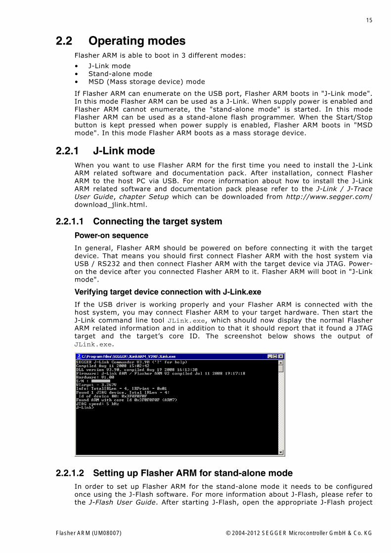
If the USB driver is working properly and your Flasher ARM is connected with thehost system, you may connect Flasher ARM to your target hardware. Then start theJ-Link command line tool JLink.exe, which should now display the normal FlasherARM related information and in addition to that it should report that it found a JTAGtarget and the target�s core ID. The screenshot below shows the output ofJLink.exe.
2.2.1.2 Setting up Flasher ARM for stand-alone modeIn order to set up Flasher ARM for the stand-alone mode it needs to be configuredonce using the J-Flash software. For more information about J-Flash, please refer tothe J-Flash User Guide. After starting J-Flash, open the appropriate J-Flash project
Flasher ARM (UM08007) © 2004-2012 SEGGER Microcontroller GmbH & Co. KG
16 CHAPTER 2 Working with Flasher ARM
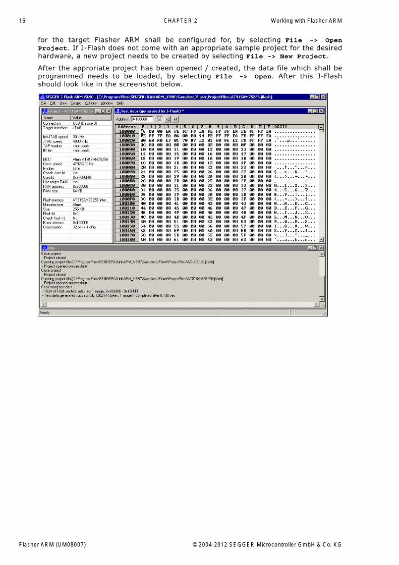
for the target Flasher ARM shall be configured for, by selecting File -> OpenProject. If J-Flash does not come with an appropriate sample project for the desiredhardware, a new project needs to be created by selecting File -> New Project.
After the approriate project has been opened / created, the data file which shall beprogrammed needs to be loaded, by selecting File -> Open. After this J-Flashshould look like in the screenshot below.
Flasher ARM (UM08007) © 2004-2012 SEGGER Microcontroller GmbH & Co. KG
17
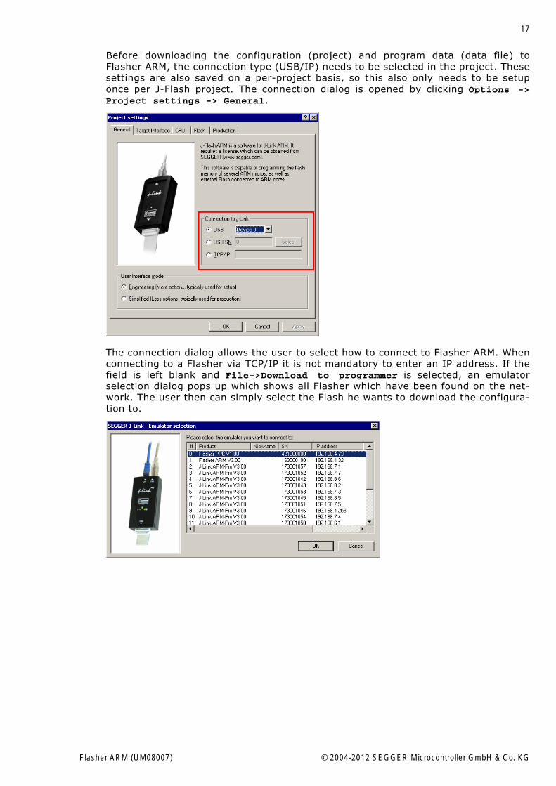
Before downloading the configuration (project) and program data (data file) toFlasher ARM, the connection type (USB/IP) needs to be selected in the project. Thesesettings are also saved on a per-project basis, so this also only needs to be setuponce per J-Flash project. The connection dialog is opened by clicking Options ->Project settings -> General.
The connection dialog allows the user to select how to connect to Flasher ARM. Whenconnecting to a Flasher via TCP/IP it is not mandatory to enter an IP address. If thefield is left blank and File->Download to programmer is selected, an emulatorselection dialog pops up which shows all Flasher which have been found on the net-work. The user then can simply select the Flash he wants to download the configura-tion to.
Flasher ARM (UM08007) © 2004-2012 SEGGER Microcontroller GmbH & Co. KG
18 CHAPTER 2 Working with Flasher ARM
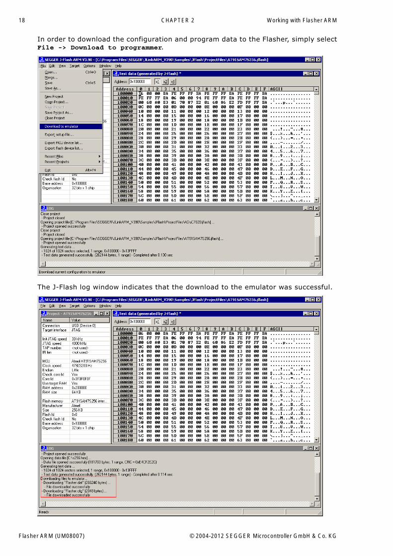
In order to download the configuration and program data to the Flasher, simply selectFile -> Download to programmer.
The J-Flash log window indicates that the download to the emulator was successful.
Flasher ARM (UM08007) © 2004-2012 SEGGER Microcontroller GmbH & Co. KG
19
From now on, Flasher ARM can be used in stand-alone mode (without host PC inter-action) for stand-alone programming.
2.2.2 Stand-alone modeBefore Flasher ARM can be used in stand-alone mode it needs to be configured once.For more information about how to setup Flasher ARM for stand-alone mode, pleaserefer to Setting up Flasher ARM for stand-alone mode on page 15. To boot FlasherARM in the "stand-alone mode", only the power supply to Flasher ARM has to beenabled (Flasher ARM should not be connected to a PC). In the "stand-alone mode"Flasher ARM can be used as a stand-alone flash programmer.
Note: Flasher ARM can only program the target device it was configured for. Inorder to program another target device, you have to repeat the steps described inSetting up Flasher ARM for stand-alone mode on page 15.
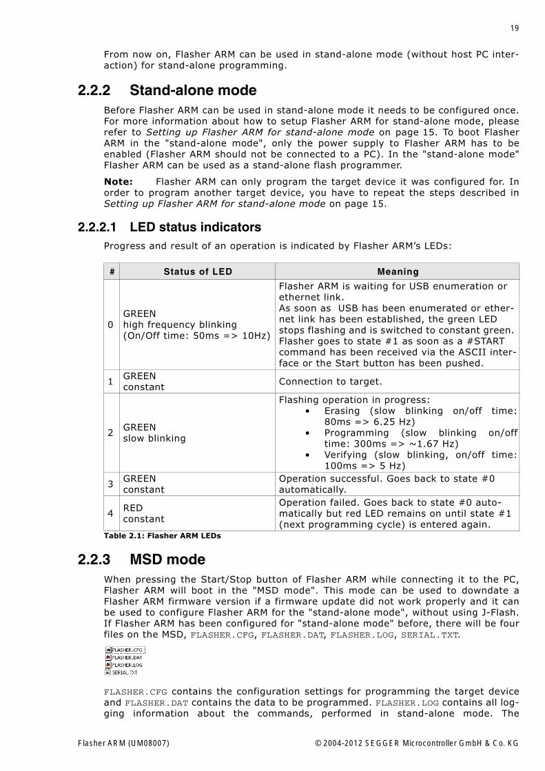
2.2.2.1 LED status indicatorsProgress and result of an operation is indicated by Flasher ARM�s LEDs:
2.2.3 MSD modeWhen pressing the Start/Stop button of Flasher ARM while connecting it to the PC,Flasher ARM will boot in the "MSD mode". This mode can be used to downdate aFlasher ARM firmware version if a firmware update did not work properly and it canbe used to configure Flasher ARM for the "stand-alone mode", without using J-Flash.If Flasher ARM has been configured for "stand-alone mode" before, there will be fourfiles on the MSD, FLASHER.CFG, FLASHER.DAT, FLASHER.LOG, SERIAL.TXT.
FLASHER.CFG contains the configuration settings for programming the target deviceand FLASHER.DAT contains the data to be programmed. FLASHER.LOG contains all log-ging information about the commands, performed in stand-alone mode. The
# Status of LED Meaning
0GREENhigh frequency blinking (On/Off time: 50ms => 10Hz)
Flasher ARM is waiting for USB enumeration or ethernet link.As soon as USB has been enumerated or ether-net link has been established, the green LED stops flashing and is switched to constant green. Flasher goes to state #1 as soon as a #START command has been received via the ASCII inter-face or the Start button has been pushed.
1 GREENconstant Connection to target.
2 GREENslow blinking
Flashing operation in progress:� Erasing (slow blinking on/off time:
80ms => 6.25 Hz)� Programming (slow blinking on/off
time: 300ms => ~1.67 Hz)� Verifying (slow blinking, on/off time:
100ms => 5 Hz)
3 GREENconstant
Operation successful. Goes back to state #0 automatically.
4 REDconstant
Operation failed. Goes back to state #0 auto-matically but red LED remains on until state #1 (next programming cycle) is entered again.
Table 2.1: Flasher ARM LEDs
Flasher ARM (UM08007) © 2004-2012 SEGGER Microcontroller GmbH & Co. KG
20 CHAPTER 2 Working with Flasher ARM
SERIAL.TXT contains the serial number, which will be programmed next. Currently, J-Flash does not support to configure Flasher ARM for automated serial number pro-gramming.
If you want to configure multiple Flasher ARM for the same target you do not have touse J-Flash all the time. It is also possible to copy the FLASHER.CFG and theFLASHER.DAT files from a configured Flasher ARM to another one. To copy these filesboot Flasher ARM in "MSD mode".
Flasher ARM (UM08007) © 2004-2012 SEGGER Microcontroller GmbH & Co. KG
21
2.3 Multiple File SupportIt is also possible to have multiple data files and config files on Flasher ARM, to makeFlasher ARM more easy to use in production environment. To choose the correct con-figuration file and data file pair, a FLASHER.INI file is used. This init file contains a[FILES] section which describes which configuration file and which data file shouldbe used for programming. A sample content of a FLASHER.INI file is shown below:
[FILES]DataFile = "Flasher1.dat"ConfigFile = "Flasher1.cfg"
Using this method all configuration files and data files which are used in the produc-tion only have to be downloaded once. From there on a configuration file / data filepair can be switched by simply replacing the FLASHER.INI by a new one, which con-tains the new descriptions for the configuration file and data file. The FLASHER.INIcan be replaced in two ways:
1. Boot Flasher ARM in MSD mode in order to replace the FLASHER.INI2. If Flasher ARM is already integrated into the production line, runs in stand-alone
mode and can not be booted in other mode: Use the file I/O commands providedby the ASCII interface of Flasher ARM, to replace the FLASHER.INI. For moreinformation about the file I/O commands, please refer to File I/O commands onpage 36.
Flasher ARM (UM08007) © 2004-2012 SEGGER Microcontroller GmbH & Co. KG
22 CHAPTER 2 Working with Flasher ARM
2.4 Serial number programmingFlasher ARM supports programming of serial numbers. In order to use the serialnumber programming feature, the J-Flash project to be used as well as some files onthe Flasher (depending on the configuration) need to be configured first.
In general, Flasher supports two ways of programming a serial number into the tar-get:
1. Programming continuous serial numbers. Serial number is 1-4 bytes in size. Startserial number, increment, serial number size and address is configured in the J-Flashproject.
2. Programming custom serial numbers from a serial number list file. Start line intoserial number list file to get next serial number bytes, line increment, serial num-ber size and address is configured in J-Flash project. Serial number list file needsto be specified and created by user.
In the following some generic information how to setup Flasher ARM & the J-Flashproject for serial number programming are given.
Note: Full serial number programming support has been introduced with V4.51dof the J-Flash software and the Flasher ARM firmware that comes with it.
Note: Currently, programming of serial numbers is only supported for stand-alone mode. Future versions of J-Flash may also support serial number programmingin J-Link mode.
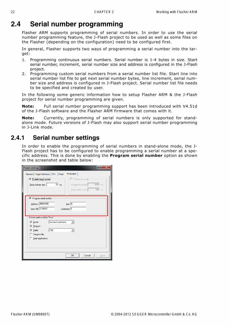
2.4.1 Serial number settingsIn order to enable the programming of serial numbers in stand-alone mode, the J-Flash project has to be configured to enable programming a serial number at a spe-cific address. This is done by enabling the Program serial number option as shownin the screenshot and table below:
Flasher ARM (UM08007) © 2004-2012 SEGGER Microcontroller GmbH & Co. KG
23
2.4.2 Serial number fileWhen selecting File -> Download serial number file to Flasher, J-Flash will cre-ate a Serial number file named as <JFlashProjectName>_Serial.txt. This file isdownloaded as SERIAL.TXT on Flasher ARM. The file is generated based on the serialnumber settings in the J-Flash project and will contain the value defined by the NextSN option. The serial number file can also be manually edited by the user, since theserial number is written ASCII encoded in the SERIAL.TXT file.
2.4.3 Serial number list fileIn order to program custom serial numbers which can not be covered by the standardserial number scheme provided by J-Flash (e.g. when programming non-continuousserial numbers or having gaps between the serial numbers), a so called serial num-ber list file needs to be created by the user.
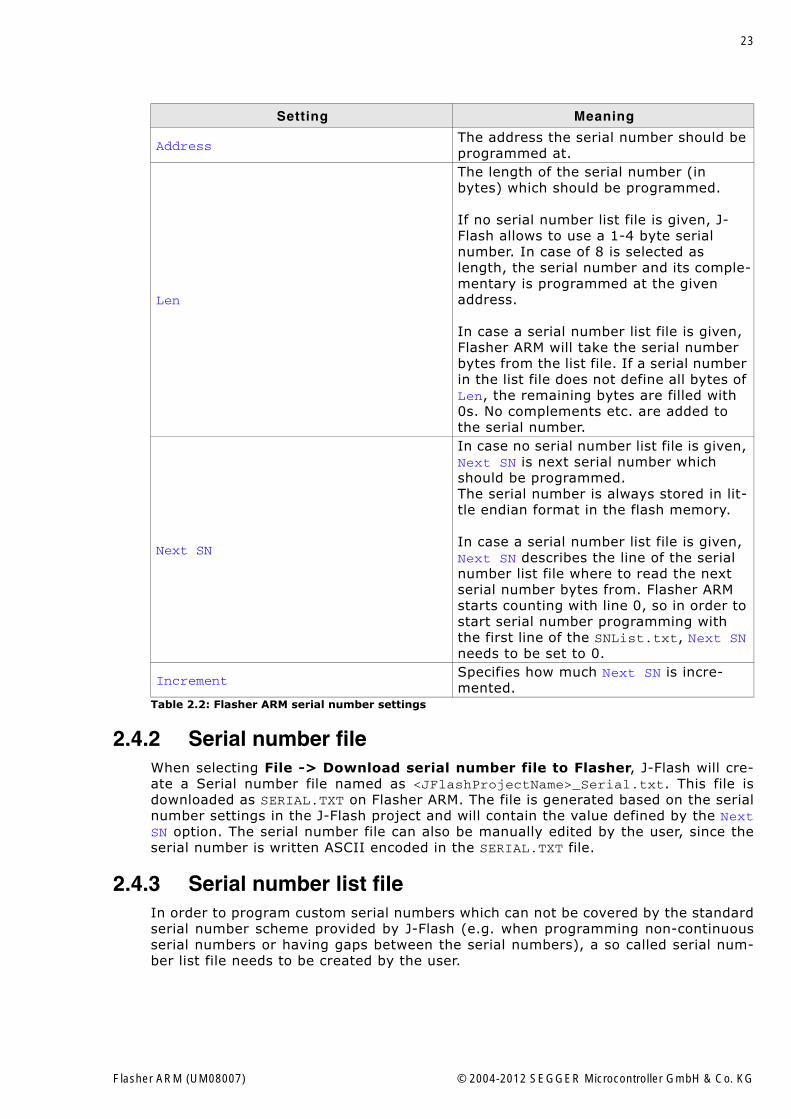
Setting Meaning
AddressThe address the serial number should be programmed at.
Len
The length of the serial number (in bytes) which should be programmed.
If no serial number list file is given, J-Flash allows to use a 1-4 byte serial number. In case of 8 is selected as length, the serial number and its comple-mentary is programmed at the given address.
In case a serial number list file is given, Flasher ARM will take the serial number bytes from the list file. If a serial number in the list file does not define all bytes of Len, the remaining bytes are filled with 0s. No complements etc. are added to the serial number.
Next SN
In case no serial number list file is given, Next SN is next serial number which should be programmed.The serial number is always stored in lit-tle endian format in the flash memory.
In case a serial number list file is given, Next SN describes the line of the serial number list file where to read the next serial number bytes from. Flasher ARM starts counting with line 0, so in order to start serial number programming with the first line of the SNList.txt, Next SN needs to be set to 0.
IncrementSpecifies how much Next SN is incre-mented.
Table 2.2: Flasher ARM serial number settings
Flasher ARM (UM08007) © 2004-2012 SEGGER Microcontroller GmbH & Co. KG
24 CHAPTER 2 Working with Flasher ARM
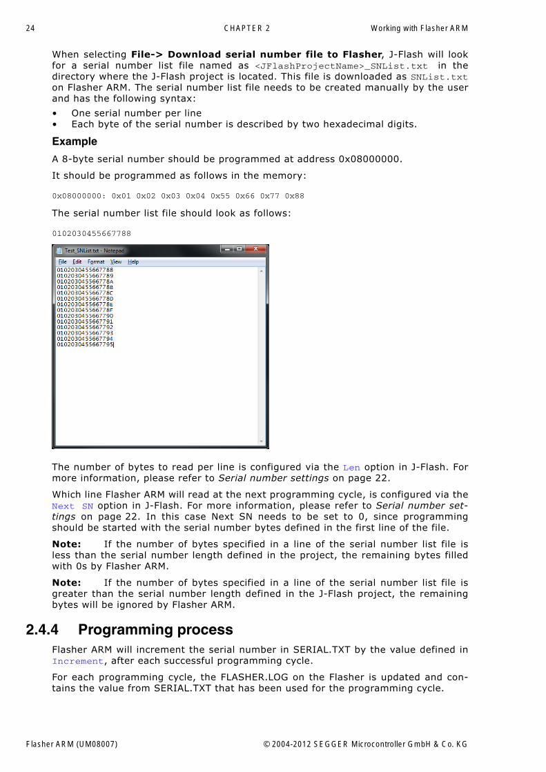
When selecting File-> Download serial number file to Flasher, J-Flash will lookfor a serial number list file named as <JFlashProjectName>_SNList.txt in thedirectory where the J-Flash project is located. This file is downloaded as SNList.txton Flasher ARM. The serial number list file needs to be created manually by the userand has the following syntax:
� One serial number per line� Each byte of the serial number is described by two hexadecimal digits.
Example
A 8-byte serial number should be programmed at address 0x08000000.
It should be programmed as follows in the memory:
0x08000000: 0x01 0x02 0x03 0x04 0x55 0x66 0x77 0x88
The serial number list file should look as follows:
0102030455667788
The number of bytes to read per line is configured via the Len option in J-Flash. Formore information, please refer to Serial number settings on page 22.
Which line Flasher ARM will read at the next programming cycle, is configured via theNext SN option in J-Flash. For more information, please refer to Serial number set-tings on page 22. In this case Next SN needs to be set to 0, since programmingshould be started with the serial number bytes defined in the first line of the file.
Note: If the number of bytes specified in a line of the serial number list file isless than the serial number length defined in the project, the remaining bytes filledwith 0s by Flasher ARM.
Note: If the number of bytes specified in a line of the serial number list file isgreater than the serial number length defined in the J-Flash project, the remainingbytes will be ignored by Flasher ARM.
2.4.4 Programming processFlasher ARM will increment the serial number in SERIAL.TXT by the value defined inIncrement, after each successful programming cycle.
For each programming cycle, the FLASHER.LOG on the Flasher is updated and con-tains the value from SERIAL.TXT that has been used for the programming cycle.
Flasher ARM (UM08007) © 2004-2012 SEGGER Microcontroller GmbH & Co. KG
25
Note: The serial number in SERIAL.TXT will also be incremented in case if serialnumber programming is disabled, to make sure that for the Flasher ARM logfile thereis a reference which programming cycle passed and which not. As long as serial num-ber programming has not been enabled in the J-Flash project, Flasher ARM does notmerge any serial number data into the image data to be programmed.
2.4.5 Downloading serial number files to Flasher ARMDownloading the serial number files needs to be done explicitly by selecting File->Download serial number file to Flasher. Please note that the File -> Downloadconfig & data file to Flasher option does only download the configuration and datafile to Flasher ARM since usually the current serial number used for programmingshall not be reset/overwritten when just updating the image Flasher ARM shall pro-gram.
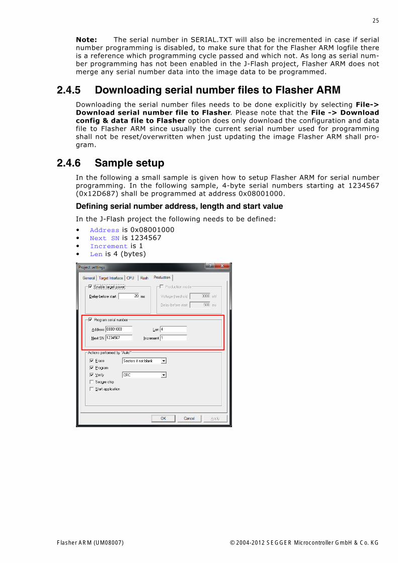
2.4.6 Sample setupIn the following a small sample is given how to setup Flasher ARM for serial numberprogramming. In the following sample, 4-byte serial numbers starting at 1234567(0x12D687) shall be programmed at address 0x08001000.
Defining serial number address, length and start value
In the J-Flash project the following needs to be defined:
� Address is 0x08001000� Next SN is 1234567� Increment is 1� Len is 4 (bytes)
Flasher ARM (UM08007) © 2004-2012 SEGGER Microcontroller GmbH & Co. KG
26 CHAPTER 2 Working with Flasher ARM
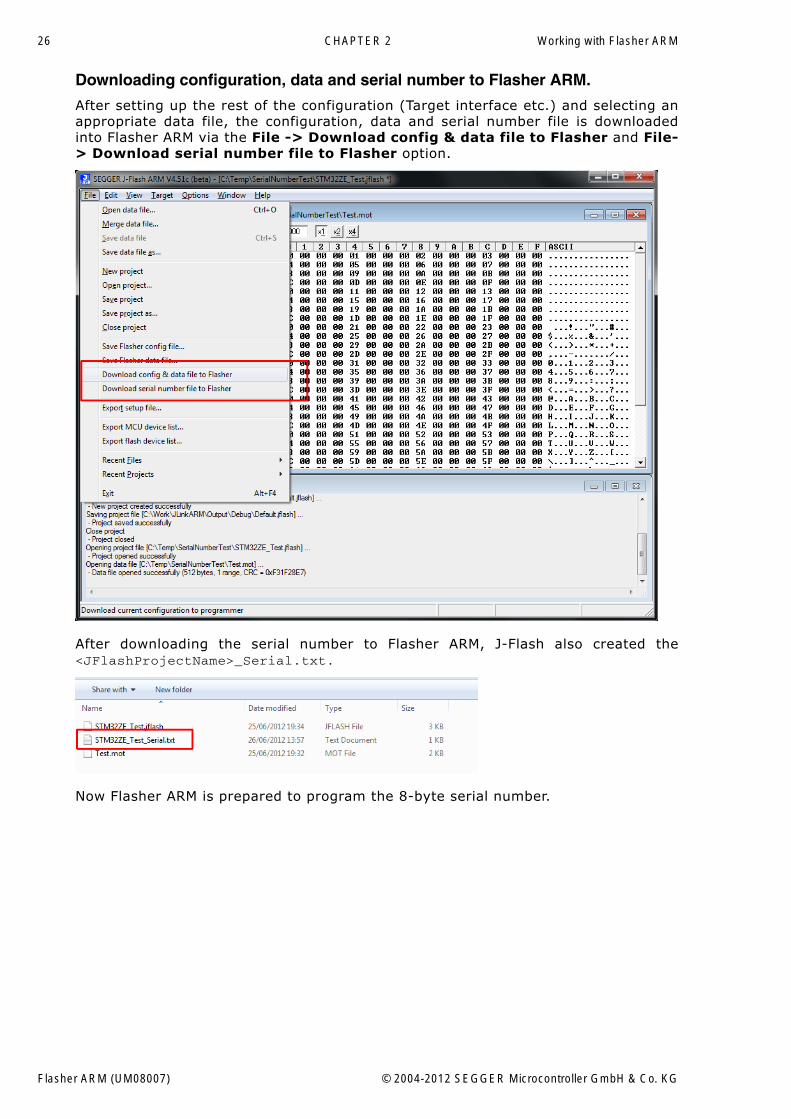
Downloading configuration, data and serial number to Flasher ARM.
After setting up the rest of the configuration (Target interface etc.) and selecting anappropriate data file, the configuration, data and serial number file is downloadedinto Flasher ARM via the File -> Download config & data file to Flasher and File-> Download serial number file to Flasher option.
After downloading the serial number to Flasher ARM, J-Flash also created the<JFlashProjectName>_Serial.txt.
Now Flasher ARM is prepared to program the 8-byte serial number.
Flasher ARM (UM08007) © 2004-2012 SEGGER Microcontroller GmbH & Co. KG
27
2.5 Target interfacesSince Flasher ARM is compatible to J-Link it also supports the same target interfaces.Currently the following target interfaces are supported:
� JTAG� SWD
For more information about the target interfaces itself and the maximum speeds thatcan be used for each target interface, please refer to UM08001, chapter "Workingwith J-Link and J-Trace", section "JTAG interface" and UM08001, chapter "Workingwith J-Link and J-Trace", section "SWD interface".
Note: Flasher ARM currently does not support SWO.
Flasher ARM (UM08007) © 2004-2012 SEGGER Microcontroller GmbH & Co. KG
28 CHAPTER 2 Working with Flasher ARM
2.6 Supported microcontrollersFlasher ARM supports download into the internal flash of a large number of microcon-trollers. The number of supported devices is steadily growing, so you can always findthe latest list of supported devices on our website:
http://www.segger.com/supported-devices.html
Flasher ARM (UM08007) © 2004-2012 SEGGER Microcontroller GmbH & Co. KG
29
2.7 Support of external flashesIn general Flasher ARM supports programming of external flashes. These flashes canbe
� parallel NOR flash� serial NOR flash� NAND flash� DataFlash
If the parallel NOR flash device which is used is not CFI-compliant you have to selectthe flash device in J-Flash explicitly, for a list of all parallel NOR flash devices whichcan be explicitly selected in J-Flash, please refer to UM08003, J-Flash User Guide,chapter Supported Flash Devices. For serial NOR flash, NAND flash and DataFlashdevices a custom RAMCode is needed since the connection of the flash to the CPU dif-fers from device to device. The J-Flash software comes with sample projects for cus-tom RAMCodes. For a complete list of all custom RAMCode projects which come withthe J-Flash software, please refer to: http://www.segger.com/supported-devices.html
Flasher ARM (UM08007) © 2004-2012 SEGGER Microcontroller GmbH & Co. KG
30 CHAPTER 2 Working with Flasher ARM
2.8 Supported ARM CoresFlasher ARM has been tested with the following cores, but should work with anyARM7/9, Cortex-M0/M1/M3 core. If you experience problems with a particular core,do not hesitate to contact Segger.
� ARM7TDMI (Rev 1)� ARM7TDMI (Rev 3)� ARM7TDMI-S (Rev 4)� ARM920T� ARM922T� ARM926EJ-S� ARM946E-S� ARM966E-S� Cortex-M0� Cortex-M1� Cortex-M3� Cortex-M4
Flasher ARM (UM08007) © 2004-2012 SEGGER Microcontroller GmbH & Co. KG
31
Chapter 3
Remote control
This chapter describes how to control Flasher ARM via the 9-pin serial interface con-nector.
Flasher ARM (UM08007) © 2004-2012 SEGGER Microcontroller GmbH & Co. KG
32 CHAPTER 3 Remote control
3.1 OverviewThere are 3 ways to control Flasher ARM operation:
� Manual: Programming operation starts when pressing the button. The LEDs serveas visible indication.
� Via Handshake lines: 3 lines on the serial interface are used.1 line is an input and can be used to start operation,2 lines are outputs and serve as Busy and status output
� Terminal communication via RS232.
Note: All three ways to control Flasher ARM operation are working only if FlasherARM is in standalone mode. In J-Link / MSD mode they have no effect.
Flasher ARM (UM08007) © 2004-2012 SEGGER Microcontroller GmbH & Co. KG
33
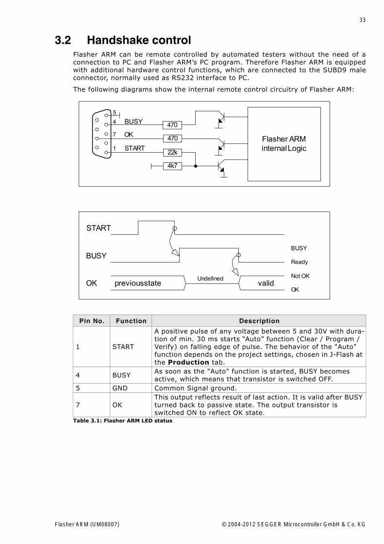
3.2 Handshake controlFlasher ARM can be remote controlled by automated testers without the need of aconnection to PC and Flasher ARM�s PC program. Therefore Flasher ARM is equippedwith additional hardware control functions, which are connected to the SUBD9 maleconnector, normally used as RS232 interface to PC.
The following diagrams show the internal remote control circuitry of Flasher ARM:
Pin No. Function Description
1 START
A positive pulse of any voltage between 5 and 30V with dura-tion of min. 30 ms starts �Auto� function (Clear / Program / Verify) on falling edge of pulse. The behavior of the "Auto" function depends on the project settings, chosen in J-Flash at the Production tab.
4 BUSY As soon as the "Auto" function is started, BUSY becomes active, which means that transistor is switched OFF.
5 GND Common Signal ground.
7 OKThis output reflects result of last action. It is valid after BUSY turned back to passive state. The output transistor is switched ON to reflect OK state.
Table 3.1: Flasher ARM LED status
470
470
22k
4k7
BUSY
OK
STARTFlasher ARMinternal Logic1
4
7
5
START
BUSY
OK previous state validOK
Not OK
Ready
BUSY
Undefined
Flasher ARM (UM08007) © 2004-2012 SEGGER Microcontroller GmbH & Co. KG
34 CHAPTER 3 Remote control
3.3 ASCII command interface
3.3.1 IntroductionOnce set up using J-Flash, Flasher ARM can be driven by any application or just asimple terminal using ASCII commands.
Every known command is acknowledged by Flasher and then executed. After com-mand execution, Flasher sends an ASCII reply message. If an unknown command isreceived, Flasher responds with #NACK.
3.3.2 General command and reply message format� Any ASCII command has to start with the start delimiter #.� Any ASCII command has to end with simple carriage return (ASCII code 13)� Commands can be sent upper or lower case.
3.3.3 Communication port settingsFlasher is driven via a RS232 serial port with the following interface settings:
� 8 data bits,� no parity� 1 stop bit
at 9600 baud.
3.3.4 Commands to FlasherThe following commands are supported by the current version of Flasher firmware:
#AUTO
The #AUTO command behaves exactly as the start button or external remote controlinput.
Usually, the following command sequence will be performed when receiving the#AUTO command:
� Flasher starts erasing� Flasher programs target CPU� Flasher verifies target CPU
Depending on the settings chosen in the Production tab in J-Flash, this sequencecan differ from the one shown above.
Finally, Flasher responds with
� #OK if no error occurred� #ERRxxx if any error occurred during operation. xxx represents the error code,
normally replied to Flasher PC program. The #ERRxxx message may be followedby an additional error text.
During execution of the #AUTO command, Flasher automatically sends �status� mes-sages via RS232 to reflect the state of execution. Typically during execution of #AUTOcommand, Flasher will reply the following sequence of messages:
#ACK#STATUS:INITIALIZING#STATUS:CONNECTING#STATUS:UNLOCKING#STATUS:ERASING#STATUS:PROGRAMMING#STATUS:VERIFYING#OK (Total 13.993s, Erase 0.483s, Prog 9.183s, Verify 2.514s)
Flasher ARM (UM08007) © 2004-2012 SEGGER Microcontroller GmbH & Co. KG
35
#AUTO NOINFO
This command may be used instead of #AUTO, if no status messages from Flashershould be sent during execution. The NOINFO extension is also available for all othercommands.
The command ends with #OK or #ERRxxx
#ERASE
This command can be sent to erase all selected target flash sectors.
Flasher will reply the following sequence of messages:
#ACK#STATUS:INITIALIZING#STATUS:CONNECTING#STATUS:UNLOCKING#STATUS:ERASING#OK (Total 0.893s, Erase 0.483s)
#START
This command can be sent to release Flasher�s target interface. All signals fromFlasher to target will be set into high-Z mode, reset of target will be released. It maybe used to start target application program.
Flasher will reply with the following sequence of messages:
#ACK#STATUS:INITIALIZING#STATUS:CONNECTING#OK (Total 1.148s)
#STATUS
This command can be sent any time, even during other command execution. Flasherresponds with its current state. All defined state messages are described under Replyfrom Flasher ARM on page 38.
#PROGRAM
This command can be used instead of #AUTO to program a target without erasing thetarget before programming and without performing a final verification.
#VERIFY
This command can used to verify the target Flash content against the data stored inFlasher.
#RESULT
This command can be sent any time, even during other command execution. Flasherresponds with the last result of the previously executed command.
#CANCEL
This command can be sent to abort a running program. It may take a while until thecurrent program is actually canceled.
Flasher will respond with:
#ERR007:CANCELED.
Flasher ARM (UM08007) © 2004-2012 SEGGER Microcontroller GmbH & Co. KG
36 CHAPTER 3 Remote control
#BAUDRATE<Baudrate>
This command can be sent in order to change the baudrate of the UART used for theASCII command interface communication. <Baudrate> is expected in decimal format.
If this command succeeds, Flasher responds with:
#ACK#OK
Otherwise it will respond with one of the following error messages:
#ERR255: Invalid parameters
or
#ERR255: Baudrate is not supported
Note: After sending the #BAUDRATE command you will first have to wait until theFlasher responds with the #OK message. It is recommended wait 5ms before sendingthe next command with the new baudrate in order to give the Flasher the time tochange the baudrate.
3.3.4.1 File I/O commandsThe ASCII interface of Flasher ARM also supports file I/O operations via RS232. Thefollowing file I/O commands are supported:
#FOPEN <Filename>
The #FOPEN command is used to open a file on Flasher for further file I/O operations.<Filename> specifies the file on the Flasher which should be opened. If <Filename>can not be found on Flasher a new one will be created.
A typical sequence using the #FOPEN command does look like as follows:
#FOPEN flasher.dat#ACK#OK
Note: Currently only one file can be open at the same time. If #FOPEN is sendand another file is already open, Flasher will respond with:
#ACK#ERR255:A file has already been opened
#FCLOSE
The #FCLOSE command closes the file on Flasher which was opened via #FOPEN. Afterthis command has been issued further file I/O operations except #FDELETE are notallowed until the #FOPEN command is send again.
A typical sequence when using the #FCLOSE command does look like as follows:
#FCLOSE#ACK#OK
Note: When using the #FCLOSE command a file has to be open (previouslyopened by #FOPEN). Otherwise Flasher will respond with the following if no file hasbeen opened:
#ACK#ERR255:No file opened
#FDELETE <Filename>
The #FDELETE command is used to delete a file on Flasher where <Filename> speci-fies the name of the file.
A typical sequence when using the #FDELETE command does look like as follows:
Flasher ARM (UM08007) © 2004-2012 SEGGER Microcontroller GmbH & Co. KG
37
#FDELETE flasher.dat#ACK#OK
Note: If deletion of the file fails for example if the file does not exist, Flasher willrespond with the following sequence:
#ACK#ERR255:Failed to delete file
#FWRITE <Offset>,<NumBytes>:<Data>
The #FWRITE command is used to write to a file on Flasher. <Offset> specifies theoffset in the file, at which data writing is started. <NumBytes> specifies the number ofbytes which are send with this command and which are written into the file onFlasher. <NumBytes> is limited to 512 bytes at once. This means, if you want to writee.g. 1024 bytes, you have to send the #FWRITE command twice, using an appropriateoffset when sending it the second time.
<Offset> and <NumBytes> are expected in hexadecimal format.
#FWRITE 0,200:<Data>#FWRITE 200,200:<Data>
The data is expected in hexadecimal format (two hexadecimal characters per byte).The following example illustrates the use of #FWRITE:
Data to be send: Hello !ASCII values: 0x48, 0x65, 0x6C, 0x6C, 0x6F, 0x20, 0x21
#FWRITE 0,7:48656C6C6F2021
Note: In order to use the #FWRITE command a file has to be opened via the#FOPEN command, first. Otherwise Flasher will respond with the following sequence:
#ACK#ERR255:No file opened
#FREAD <Offset>,<NumBytes>
The #FREAD command is used to read data from a file on Flasher. <Offset> specifiesthe offset in the file, at which data reading is started. <NumBytes> specifies the num-ber of bytes which should be read.
A typical sequence when using the #FREAD command does look like as follows:
#FREAD 0,4#ACK#OK:04:466c6173
If the #FREAD command succeeds, Flasher will finally respond with a #OK:<Num-Bytes>:<Data> reply message. For more information about the Flasher reply mes-sages, please refer to Reply from Flasher ARM on page 38.
Note: In order to use the #FREAD command. A file has to be opened before, viathe #FOPEN command. Otherwise Flasher will respond with the following sequence:
#ACK#ERR255:No file opened
#FSIZE
The #FSIZE command is used to get the size of the currently opened file on Flasher.
A typical sequence when using the #FSIZE command does look like as follows:
#FSIZE#ACK#OK:10 // file on flasher which is currently open, has a size of 16 bytes
Flasher ARM (UM08007) © 2004-2012 SEGGER Microcontroller GmbH & Co. KG
38 CHAPTER 3 Remote control
If the #FSIZE command succeeds, Flasher will respond with a #OK:<Size> reply mes-sage. For more information about the Flasher reply messages, please refer to Replyfrom Flasher ARM on page 38.
Note: In order to use the #FREAD command. A file has to be opened before, viathe #FOPEN command. Otherwise Flasher will respond with the following sequence:
#ACK#ERR255:No file opened
3.3.5 Reply from Flasher ARMThe reply messages from Flasher follow the same data format as commands. Anyreply message starts with ASCII start delimiter #, ends with simple carriage return(ASCII code 13) and is sent in uppercase. In contrast to commands, replies can befollowed by a description message, which gives more detailed information about thereply. This description is sent in mixed case. The #OK reply, for example, is such areply. It is followed by a string containing information about the performance timeneeded for the operations:
#OK (Total 13.993s, Erase 0.483s, Prog 9.183s, Verify 2.514s)
The following reply messages from Flasher are defined:
#ACK
Flasher replies with #ACK message on reception of any defined command before thecommand itself is executed.
#NACK
Flasher replies with #NACK, if an undefined command was received.
#OK
Flasher replies with #OK, if a command other then #STATUS or #RESULT was executedand ended with no error.
#OK:<NumBytes>:<Data>
Flasher replies with #OK:<Len>:<Data> if a #FREAD command was executed. <Num-Bytes> is the number of bytes which could be read. This value may differ from thenumber of requested bytes, for example if more bytes than available, wererequested. <NumBytes> and <Data> are send in hexadecimal format (for <Data>: twohexadecimal characters per byte).
#OK:<Size>
Flasher replies if #OK:<Size> if a #FSIZE command has been executed. <Size> is thesize (in bytes) of the currently opened file. <Size> is send in hexadecimal format.
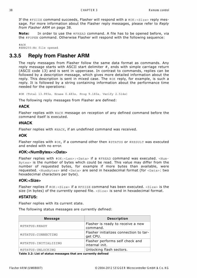
#STATUS:
Flasher replies with its current state.
The following status messages are currently defined:
Message Description
#STATUS:READYFlasher is ready to receive a new command.
#STATUS:CONNECTINGFlasher initializes connection to tar-get CPU.
#STATUS:INITIALIZINGFlasher performs self check and internal init.
#STATUS:UNLOCKING Unlocking flash sectors.Table 3.2: List of status messages that are currently defined
Flasher ARM (UM08007) © 2004-2012 SEGGER Microcontroller GmbH & Co. KG
39
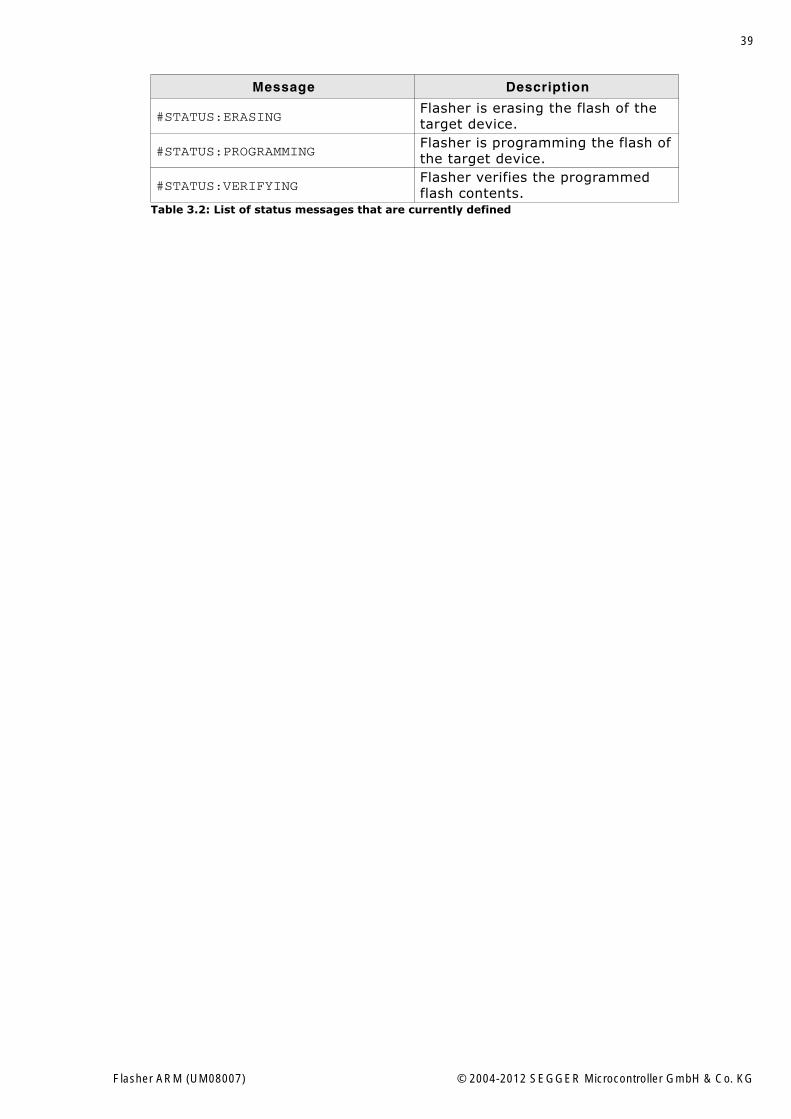
#STATUS:ERASINGFlasher is erasing the flash of the target device.
#STATUS:PROGRAMMINGFlasher is programming the flash of the target device.
#STATUS:VERIFYINGFlasher verifies the programmed flash contents.
Message Description
Table 3.2: List of status messages that are currently defined
Flasher ARM (UM08007) © 2004-2012 SEGGER Microcontroller GmbH & Co. KG
40 CHAPTER 3 Remote control
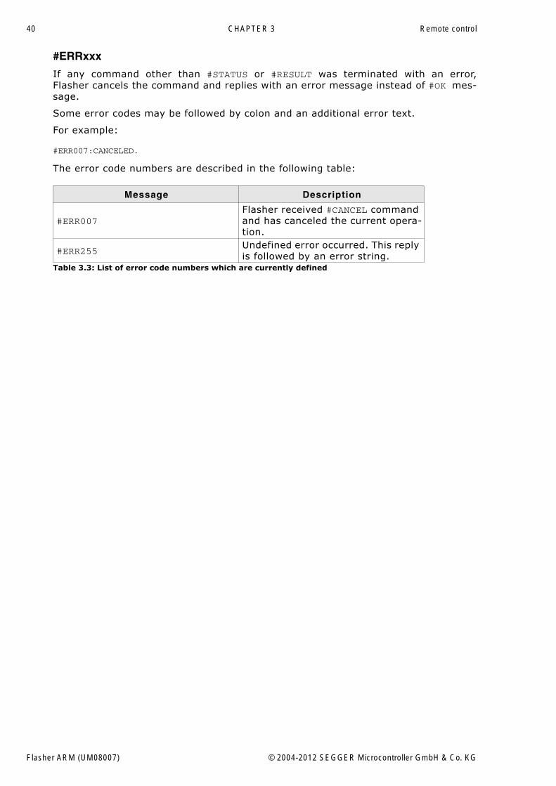
#ERRxxx
If any command other than #STATUS or #RESULT was terminated with an error,Flasher cancels the command and replies with an error message instead of #OK mes-sage.
Some error codes may be followed by colon and an additional error text.
For example:
#ERR007:CANCELED.
The error code numbers are described in the following table:
Message Description
#ERR007Flasher received #CANCEL command and has canceled the current opera-tion.
#ERR255Undefined error occurred. This reply is followed by an error string.
Table 3.3: List of error code numbers which are currently defined
Flasher ARM (UM08007) © 2004-2012 SEGGER Microcontroller GmbH & Co. KG
41
Chapter 4
Performance
The following chapter lists programming performance of common flash devices andmicrocontrollers.
Flasher ARM (UM08007) © 2004-2012 SEGGER Microcontroller GmbH & Co. KG
42 CHAPTER 4 Performance
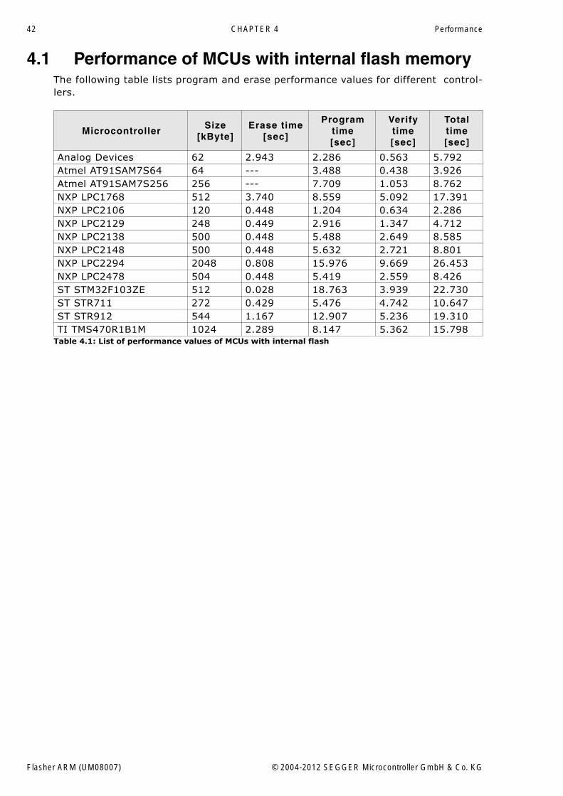
4.1 Performance of MCUs with internal flash memoryThe following table lists program and erase performance values for different control-lers.
MicrocontrollerSize
[kByte]Erase time
[sec]
Programtime[sec]
Verifytime[sec]
Total time [sec]
Analog Devices 62 2.943 2.286 0.563 5.792Atmel AT91SAM7S64 64 --- 3.488 0.438 3.926Atmel AT91SAM7S256 256 --- 7.709 1.053 8.762NXP LPC1768 512 3.740 8.559 5.092 17.391NXP LPC2106 120 0.448 1.204 0.634 2.286NXP LPC2129 248 0.449 2.916 1.347 4.712NXP LPC2138 500 0.448 5.488 2.649 8.585NXP LPC2148 500 0.448 5.632 2.721 8.801NXP LPC2294 2048 0.808 15.976 9.669 26.453NXP LPC2478 504 0.448 5.419 2.559 8.426ST STM32F103ZE 512 0.028 18.763 3.939 22.730ST STR711 272 0.429 5.476 4.742 10.647ST STR912 544 1.167 12.907 5.236 19.310TI TMS470R1B1M 1024 2.289 8.147 5.362 15.798
Table 4.1: List of performance values of MCUs with internal flash
Flasher ARM (UM08007) © 2004-2012 SEGGER Microcontroller GmbH & Co. KG
43
Chapter 5
Hardware
This chapter gives an overview about Flasher ARM specific hardware details, such asthe pinouts and available adapters.
Flasher ARM (UM08007) © 2004-2012 SEGGER Microcontroller GmbH & Co. KG
44 CHAPTER 5 Hardware
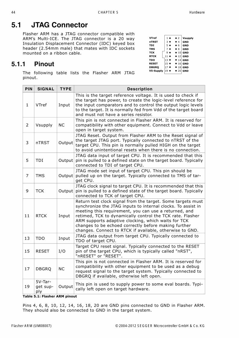
5.1 JTAG ConnectorFlasher ARM has a JTAG connector compatible withARM�s Multi-ICE. The JTAG connector is a 20 wayInsulation Displacement Connector (IDC) keyed boxheader (2.54mm male) that mates with IDC socketsmounted on a ribbon cable.
5.1.1 PinoutThe following table lists the Flasher ARM JTAGpinout.
Pins 4, 6, 8, 10, 12, 14, 16, 18, 20 are GND pins connected to GND in Flasher ARM.They should also be connected to GND in the target system.
PIN SIGNAL TYPE Description
1 VTref Input
This is the target reference voltage. It is used to check if the target has power, to create the logic-level reference for the input comparators and to control the output logic levels to the target. It is normally fed from Vdd of the target board and must not have a series resistor.
2 Vsupply NCThis pin is not connected in Flasher ARM. It is reserved for compatibility with other equipment. Connect to Vdd or leave open in target system.
3 nTRST Output
JTAG Reset. Output from Flasher ARM to the Reset signal of the target JTAG port. Typically connected to nTRST of the target CPU. This pin is normally pulled HIGH on the target to avoid unintentional resets when there is no connection.
5 TDI OutputJTAG data input of target CPU. It is recommended that this pin is pulled to a defined state on the target board. Typically connected to TDI of target CPU.
7 TMS OutputJTAG mode set input of target CPU. This pin should be pulled up on the target. Typically connected to TMS of tar-get CPU.
9 TCK OutputJTAG clock signal to target CPU. It is recommended that this pin is pulled to a defined state of the target board. Typically connected to TCK of target CPU.
11 RTCK Input
Return test clock signal from the target. Some targets must synchronize the JTAG inputs to internal clocks. To assist in meeting this requirement, you can use a returned, and retimed, TCK to dynamically control the TCK rate. Flasher ARM supports adaptive clocking, which waits for TCK changes to be echoed correctly before making further changes. Connect to RTCK if available, otherwise to GND.
13 TDO Input JTAG data output from target CPU. Typically connected to TDO of target CPU.
15 RESET I/OTarget CPU reset signal. Typically connected to the RESET pin of the target CPU, which is typically called "nRST", "nRESET" or "RESET".
17 DBGRQ NC
This pin is not connected in Flasher ARM. It is reserved for compatibility with other equipment to be used as a debug request signal to the target system. Typically connected to DBGRQ if available, otherwise left open.
195V-Tar-get sup-ply
Output This pin is used to supply power to some eval boards. Typi-cally left open on target hardware.
Table 5.1: Flasher ARM pinout
1 2
3 45 6
7 89 10
11 12
13 1415 16
17 1819 20
VTref
nTRSTTDI
TMSTCK
RTCK
TDORESET
DBGRQV5-Supply
Vsupply
GND
GNDGND
GND
GNDGND
GNDGND
GND
Flasher ARM (UM08007) © 2004-2012 SEGGER Microcontroller GmbH & Co. KG
45
5.1.2 Target board design for JTAGWe strongly advise following the recommendations given by the chip manufacturer.These recommendations are normally in line with the recommendations given in thetable Pinout on page 44. In case of doubt you should follow the recommendationsgiven by the semiconductor manufacturer.
5.1.2.1 Pull-up/pull-down resistorsUnless otherwise specified by developer�s manual, pull-ups/pull-downs are recom-mended to be between 2.2 kOhms and 47 kOhms.
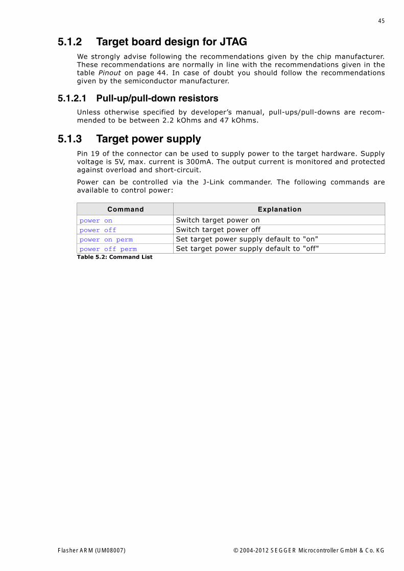
5.1.3 Target power supplyPin 19 of the connector can be used to supply power to the target hardware. Supplyvoltage is 5V, max. current is 300mA. The output current is monitored and protectedagainst overload and short-circuit.
Power can be controlled via the J-Link commander. The following commands areavailable to control power:
Command Explanation
power on Switch target power onpower off Switch target power offpower on perm Set target power supply default to "on"power off perm Set target power supply default to "off"
Table 5.2: Command List
Flasher ARM (UM08007) © 2004-2012 SEGGER Microcontroller GmbH & Co. KG
46 CHAPTER 5 Hardware
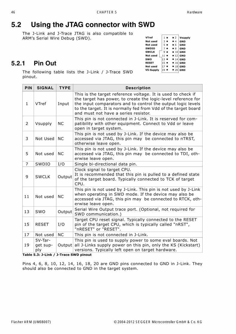
5.2 Using the JTAG connector with SWDThe J-Link and J-Trace JTAG is also compatible toARM�s Serial Wire Debug (SWD).
5.2.1 Pin OutThe following table lists the J-Link / J-Trace SWDpinout.
Pins 4, 6, 8, 10, 12, 14, 16, 18, 20 are GND pins connected to GND in J-Link. Theyshould also be connected to GND in the target system.
PIN SIGNAL TYPE Description
1 VTref Input
This is the target reference voltage. It is used to check if the target has power, to create the logic-level reference for the input comparators and to control the output logic levels to the target. It is normally fed from Vdd of the target board and must not have a series resistor.
2 Vsupply NCThis pin is not connected in J-Link. It is reserved for com-patibility with other equipment. Connect to Vdd or leave open in target system.
3 Not Used NCThis pin is not used by J-Link. If the device may also be accessed via JTAG, this pin may be connected to nTRST, otherwise leave open.
5 Not used NCThis pin is not used by J-Link. If the device may also be accessed via JTAG, this pin may be connected to TDI, oth-erwise leave open.
7 SWDIO I/O Single bi-directional data pin.
9 SWCLK Output
Clock signal to target CPU.It is recommended that this pin is pulled to a defined state of the target board. Typically connected to TCK of target CPU.
11 Not used NC
This pin is not used by J-Link. This pin is not used by J-Link when operating in SWD mode. If the device may also be accessed via JTAG, this pin may be connected to RTCK, oth-erwise leave open.
13 SWO Output Serial Wire Output trace port. (Optional, not required for SWD communication.)
15 RESET I/OTarget CPU reset signal. Typically connected to the RESET pin of the target CPU, which is typically called "nRST", "nRESET" or "RESET".
17 Not used NC This pin is not connected in J-Link.
195V-Tar-get sup-ply
OutputThis pin is used to supply power to some eval boards. Not all J-Links supply power on this pin, only the KS (Kickstart) versions. Typically left open on target hardware.
Table 5.3: J-Link / J-Trace SWD pinout
1 2
3 45 6
7 89 10
11 12
13 1415 16
17 1819 20
VTref
Not usedNot used
SWDIOSWCLK
Not used
SWORESET
Not usedV5-Supply
Vsupply
GND
GNDGND
GND
GNDGND
GNDGND
GND
Flasher ARM (UM08007) © 2004-2012 SEGGER Microcontroller GmbH & Co. KG
47
5.3 RESET, nTRSTThe TAP controller and ICE logic is reset independently from the ARM core withnTRST (DBGnTRST on synthesizable cores). For the ARM core to operate correctly, itis essential that both signals are asserted after power-up.
The advantage of having separate connection to the two reset signals is that it allowsthe developer performing software debug to setup breakpoints, which are retained bythe ICE logic even when the core is reset. (For example, at address 0, to allow thecode to be single-stepped as soon as it comes out of reset). This can be particularlyuseful when first trying to bring up a board with a new ASIC.
You may tie (DBG)nTRST to the core reset, but this removes some of the flexibilityand usefulness of the debug tools. What some designers who are facing similar pinconstraints have done is to implement some kind of reset circuit within their device.This typically will assert both nTRST and the core reset for the initial power-on reset,but subsequent 'warm' resets, where the power to the device is maintained, willcause only the core reset to go LOW.
Flasher ARM (UM08007) © 2004-2012 SEGGER Microcontroller GmbH & Co. KG
48 CHAPTER 5 Hardware
5.4 Adapters
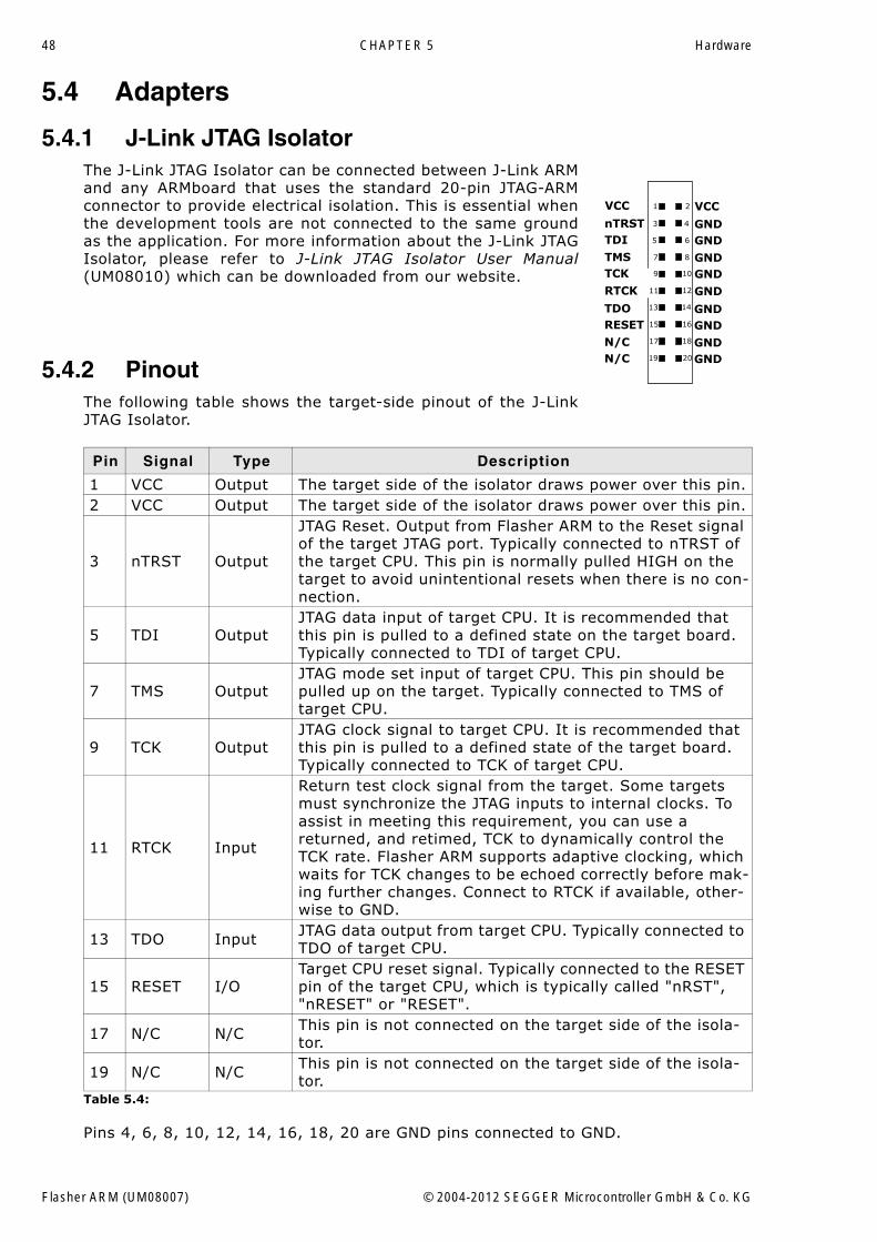
5.4.1 J-Link JTAG IsolatorThe J-Link JTAG Isolator can be connected between J-Link ARMand any ARMboard that uses the standard 20-pin JTAG-ARMconnector to provide electrical isolation. This is essential whenthe development tools are not connected to the same groundas the application. For more information about the J-Link JTAGIsolator, please refer to J-Link JTAG Isolator User Manual(UM08010) which can be downloaded from our website.
5.4.2 PinoutThe following table shows the target-side pinout of the J-LinkJTAG Isolator.
Pins 4, 6, 8, 10, 12, 14, 16, 18, 20 are GND pins connected to GND.
Pin Signal Type Description
1 VCC Output The target side of the isolator draws power over this pin.2 VCC Output The target side of the isolator draws power over this pin.
3 nTRST Output
JTAG Reset. Output from Flasher ARM to the Reset signal of the target JTAG port. Typically connected to nTRST of the target CPU. This pin is normally pulled HIGH on the target to avoid unintentional resets when there is no con-nection.
5 TDI OutputJTAG data input of target CPU. It is recommended that this pin is pulled to a defined state on the target board. Typically connected to TDI of target CPU.
7 TMS OutputJTAG mode set input of target CPU. This pin should be pulled up on the target. Typically connected to TMS of target CPU.
9 TCK OutputJTAG clock signal to target CPU. It is recommended that this pin is pulled to a defined state of the target board. Typically connected to TCK of target CPU.
11 RTCK Input
Return test clock signal from the target. Some targets must synchronize the JTAG inputs to internal clocks. To assist in meeting this requirement, you can use a returned, and retimed, TCK to dynamically control the TCK rate. Flasher ARM supports adaptive clocking, which waits for TCK changes to be echoed correctly before mak-ing further changes. Connect to RTCK if available, other-wise to GND.
13 TDO Input JTAG data output from target CPU. Typically connected to TDO of target CPU.
15 RESET I/OTarget CPU reset signal. Typically connected to the RESET pin of the target CPU, which is typically called "nRST", "nRESET" or "RESET".
17 N/C N/C This pin is not connected on the target side of the isola-tor.
19 N/C N/C This pin is not connected on the target side of the isola-tor.
Table 5.4:
1
3
5
7
9
11
13
15
17
19
VCC
nTRSTTDI
TMSTCK
RTCK
TDORESET
N/CN/C
VCC
GND
GNDGND
GND
GNDGND
GNDGND
GND
2
4
6
8
10
12
14
16
18
20
Flasher ARM (UM08007) © 2004-2012 SEGGER Microcontroller GmbH & Co. KG
49
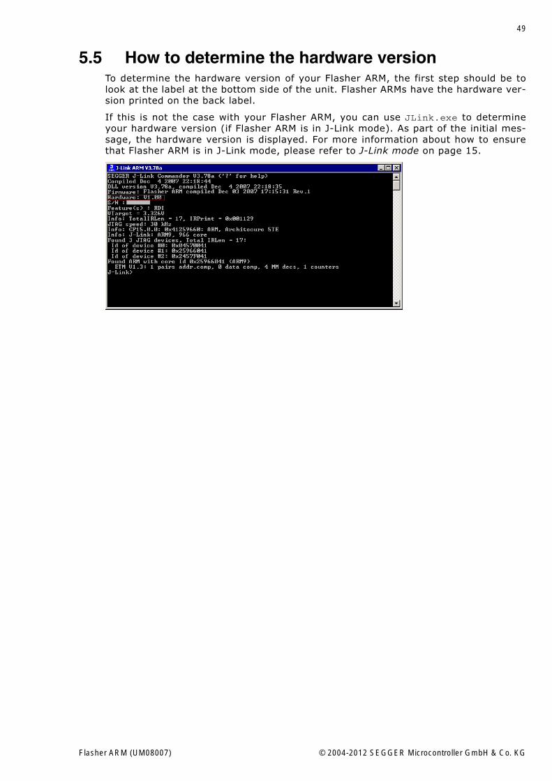
5.5 How to determine the hardware versionTo determine the hardware version of your Flasher ARM, the first step should be tolook at the label at the bottom side of the unit. Flasher ARMs have the hardware ver-sion printed on the back label.
If this is not the case with your Flasher ARM, you can use JLink.exe to determineyour hardware version (if Flasher ARM is in J-Link mode). As part of the initial mes-sage, the hardware version is displayed. For more information about how to ensurethat Flasher ARM is in J-Link mode, please refer to J-Link mode on page 15.
Flasher ARM (UM08007) © 2004-2012 SEGGER Microcontroller GmbH & Co. KG

50 CHAPTER 5 Hardware
Flasher ARM (UM08007) © 2004-2012 SEGGER Microcontroller GmbH & Co. KG
51
Chapter 6
Background information
This chapter provides background information about flash programming in general. Italso provides information about how to replace the firmware of Flasher ARM manu-ally.
Flasher ARM (UM08007) © 2004-2012 SEGGER Microcontroller GmbH & Co. KG
52 CHAPTER 6 Background information
6.1 Flash programmingFlasher ARM comes with a DLL, which allows - amongst other functionalities - readingand writing RAM, CPU registers, starting and stopping the CPU, and setting break-points.
6.1.1 How does flash programming via Flasher ARM work ?This requires extra code. This extra code typically downloads a program into the RAMof the target system, which is able to erase and program the flash. This program iscalled RAM code and "knows" how to program the flash; it contains an implementa-tion of the flash programming algorithm for the particular flash. Different flash chipshave different programming algorithms; the programming algorithm also depends onother things, such as endianess of the target system and organization of the flashmemory (for example 1 * 8 bits, 1 * 16 bits, 2 * 16 bits or 32 bits). The RAM coderequires data to be programmed into the flash memory. The data is supplied bydownloading it to RAM.
6.1.2 Data download to RAMThe data (or part of it) is downloaded to another part of the RAM of the target sys-tem. The Instruction pointer (R15) of the CPU is then set to the start address of theRam code, the CPU is started, executing the RAM code. The RAM code, which con-tains the programming algorithm for the flash chip, copies the data into the flashchip. The CPU is stopped after this. This process may have to be repeated until theentire data is programmed into the flash.
6.1.3 Available options for flash programmingIn general, there are two possibilities in order to use Flasher ARM for flash program-ming:
� Using Flash ARM stand-alone to program the target flash memory (stand-alonemode)
� Using Flasher ARM in combination with J-Flash to program the target flash mem-ory (Flasher ARM in "J-Link mode")
6.1.3.1 Using Flasher ARM in stand-alone modeIn order to use the Flasher ARM in stand-alone mode, it has to be configured first.For more information about how to setup Flasher ARM for using in "stand-alonemode", please refer to Setting up Flasher ARM for stand-alone mode on page 15.
6.1.3.2 J-Flash - Complete flash programming solutionJ-Flash is a stand-alone Windows application, which can read / write data files andprogram the flash in almost any ARM system. Flasher ARM has a build-in license forJ-Flash, so no extra license is required. For more information about J-Flash pleaserefer to the J-Flash User Guide, which can be downloaded from our website http://www.segger.com.
Flasher ARM (UM08007) © 2004-2012 SEGGER Microcontroller GmbH & Co. KG
53
Chapter 7
Support and FAQs
This chapter contains troubleshooting tips together with solutions for common prob-lems which might occur when using Flasher ARM. There are several steps you cantake before contacting support. Performing these steps can solve many problems andoften eliminates the need for assistance. This chapter also contains a collection offrequently asked questions (FAQs) with answers.
Flasher ARM (UM08007) © 2004-2012 SEGGER Microcontroller GmbH & Co. KG
54 CHAPTER 7 Support and FAQs
7.1 Contacting supportBefore contacting support, make sure you tried to solve your problem by trying yourFlasher ARM with another PC and if possible with another target system to see if itworks there. If the device functions correctly, the USB setup on the original machineor your target hardware is the source of the problem, not Flasher ARM.
If you need to contact support, send the following information to [email protected]:
� A detailed description of the problem� Flasher ARM serial number� Information about your target hardware (processor, board, etc.).� FLASHER.CFG, FLASHER.DAT, FLASHER.LOG, SERIAL.TXT file from Flasher ARM. To
get these files, Flasher ARM has to be in MSD mode. For more information abouthow to boot Flasher ARM in MSD mode, please refer to MSD mode on page 19.
Flasher ARM is sold directly by SEGGER.
Flasher ARM (UM08007) © 2004-2012 SEGGER Microcontroller GmbH & Co. KG
55
7.2 Frequently Asked QuestionsMaximum JTAG speed
Q: What is the maximum JTAG speed supported by Flasher ARM?A: Flasher ARM�s maximum supported JTAG speed is 12MHz.
Maximum download speedQ: What is the maximum download speed?A: The maximum download speed is currently about 720 Kbytes/second when down-
loading into RAM. The actual speed depends on various factors, such as JTAG,clock speed, host CPU core etc.
Flasher ARM (UM08007) © 2004-2012 SEGGER Microcontroller GmbH & Co. KG
56 CHAPTER 7 Support and FAQs
Flasher ARM (UM08007) © 2004-2012 SEGGER Microcontroller GmbH & Co. KG
57
Chapter 8
Glossary
This chapter describes important terms used throughout this manual.
Flasher ARM (UM08007) © 2004-2012 SEGGER Microcontroller GmbH & Co. KG
58 CHAPTER 8 Glossary
Adaptive clocking
A technique in which a clock signal is sent out by Flasher ARM. Flasher ARM waits forthe returned clock before generating the next clock pulse. The technique allows theFlasher ARM interface unit to adapt to differing signal drive capabilities and differingcable lengths.
Big-endian
Memory organization where the least significant byte of a word is at a higher addressthan the most significant byte. See Little-endian.
Cache cleaning
The process of writing dirty data in a cache to main memory.
Coprocessor
An additional processor that is used for certain operations, for example, for floating-point math calculations, signal processing, or memory management.
Dirty data
When referring to a processor data cache, data that has been written to the cachebut has not been written to main memory is referred to as dirty data. Only write-backcaches can have dirty data because a write-through cache writes data to the cacheand to main memory simultaneously. See also cache cleaning.
EmbeddedICE
The additional hardware provided by ARM7/9 processors to aid debugging.
Halfword
A 16-bit unit of information.
Host
A computer which provides data and other services to another computer. Especially, acomputer providing debugging services to a target being debugged.
ICache
Instruction cache.
ID
Identifier.
IEEE 1149.1
The IEEE Standard which defines TAP. Commonly (but incorrectly) referred to asJTAG.
Image
An executable file that has been loaded onto a processor for execution.
Instruction Register
When referring to a TAP controller, a register that controls the operation of the TAP.
IR
See Instruction Register.
Joint Test Action Group (JTAG)
The name of the standards group which created the IEEE 1149.1 specification.
Little-endian
Memory organization where the least significant byte of a word is at a lower addressthan the most significant byte. See also Big-endian.
Flasher ARM (UM08007) © 2004-2012 SEGGER Microcontroller GmbH & Co. KG
59
Memory coherency
A memory is coherent if the value read by a data read or instruction fetch is thevalue that was most recently written to that location. Obtaining memory coherency isdifficult when there are multiple possible physical locations that are involved, such asa system that has main memory, a write buffer, and a cache.
Memory management unit (MMU)
Hardware that controls caches and access permissions to blocks of memory, andtranslates virtual to physical addresses.
Memory Protection Unit (MPU)
Hardware that controls access permissions to blocks of memory. Unlike an MMU, aMPU does not translate virtual addresses to physical addresses.
RESET
Abbreviation of System Reset. The electronic signal which causes the target systemother than the TAP controller to be reset. This signal is also known as "nSRST""nSYSRST", "nRST", or "nRESET" in some other manuals. See also nTRST.
nTRST
Abbreviation of TAP Reset. The electronic signal that causes the target system TAPcontroller to be reset. This signal is known as nICERST in some other manuals. Seealso nSRST.
Open collector
A signal that may be actively driven LOW by one or more drivers, and is otherwisepassively pulled HIGH. Also known as a "wired AND" signal.
Processor Core
The part of a microprocessor that reads instructions from memory and executesthem, including the instruction fetch unit, arithmetic and logic unit, and the registerbank. It excludes optional coprocessors, caches, and the memory management unit.
Remapping
Changing the address of physical memory or devices after the application has started
executing. This is typically done to make RAM replace ROM once the initialization hasbeen done.
RTCK
Returned TCK. The signal which enables Adaptive Clocking.
RTOS
Real Time Operating System.
TAP Controller
Logic on a device which allows access to some or all of that device for test purposes.The circuit functionality is defined in IEEE1149.1.
Target
The actual processor (real silicon or simulated) on which the application program isrunning.
TCK
The electronic clock signal which times data on the TAP data lines TMS, TDI, andTDO.
Flasher ARM (UM08007) © 2004-2012 SEGGER Microcontroller GmbH & Co. KG
60 CHAPTER 8 Glossary
TDI
The electronic signal input to a TAP controller from the data source (upstream). Usu-ally, this is seen connecting the J-Link / J-Trace Interface Unit to the first TAP control-ler.
TDO
The electronic signal output from a TAP controller to the data sink (downstream).Usually, this is seen connecting the last TAP controller to the J-Link / J-Trace Inter-face Unit.
Test Access Port (TAP)
The port used to access a device's TAP Controller. Comprises TCK, TMS, TDI, TDO,and nTRST (optional).
Transistor-transistor logic (TTL)
A type of logic design in which two bipolar transistors drive the logic output to one orzero. LSI and VLSI logic often used TTL with HIGH logic level approaching +5V andLOW approaching 0V.
Word
A 32-bit unit of information. Contents are taken as being an unsigned integer unlessotherwise stated.
Flasher ARM (UM08007) © 2004-2012 SEGGER Microcontroller GmbH & Co. KG
61
Chapter 9
Literature and references
This chapter lists documents, which we think may be useful to gain a deeper under-standing of technical details.
Flasher ARM (UM08007) © 2004-2012 SEGGER Microcontroller GmbH & Co. KG
62 CHAPTER 9 Literature and references
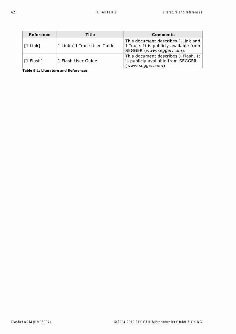
Reference Title Comments
[J-Link] J-Link / J-Trace User GuideThis document describes J-Link and J-Trace. It is publicly available from SEGGER (www.segger.com).
[J-Flash] J-Flash User GuideThis document describes J-Flash. It is publicly available from SEGGER (www.segger.com).
Table 9.1: Literature and References
Flasher ARM (UM08007) © 2004-2012 SEGGER Microcontroller GmbH & Co. KG
63
Index
AAdaptive clocking .................................58
BBig-endian ..........................................58
CCache cleaning ....................................58Coprocessor ........................................58
DDirty data ...........................................58
EEmbeddedICE .....................................58
HHalfword .............................................58Host ...................................................58
IICache ...............................................58ID .....................................................58IEEE 1149.1 ........................................58Image ................................................58Instruction Register ..............................58IR ......................................................58
JJ-Link
Adapters ..........................................48Features ...........................................10Specifications ....................................11Supported chips .......................... 30, 47
Joint Test Action Group (JTAG) ...............58JTAG
PINs ................................................44
LLittle-endian ....................................... 58
MMemory coherency .............................. 59Memory management unit (MMU) ......... 59Memory Protection Unit (MPU) .............. 59
NnTRST .......................................... 44, 59
OOpen collector .................................... 59
PProcessor Core ................................... 59
RRemapping ......................................... 59RESET ............................................... 59RTCK ................................................. 59RTOS ................................................. 59
SSupport ........................................ 53, 57
TTAP Controller .................................... 59Target ............................................... 59TCK .............................................. 44, 59TDI .............................................. 44, 60TDO ............................................. 44, 60Test Access Port (TAP) ......................... 60Transistor-transistor logic (TTL) ............. 60
WWord ................................................. 60
Flasher ARM (UM08007) © 2004-2012 SEGGER Microcontroller GmbH & Co. KG

64 Index
Flasher ARM (UM08007) © 2004-2012 SEGGER Microcontroller GmbH & Co. KG