Embed Size (px)
Citation preview
-
CONNECT SYSTEMS INCORPORATED 1802 Eastman Ave., Suite 116
Ventura, Ca. 93003
Phone (805) 642-7184 Fax (805) 642-7271
FLEX SERIES UNIVERSAL CONTROLLER
FLEX IV DSP DISPATCH CONTROLLER
User’s Instruction Manual
Made in U.S.A. Copyright 2006 By Connect Systems Inc.
CONNECT SYSTEM INC. FLEX IV DSP DISPATCH CONTROLLER Page 2
CONNECT SYSTEMS INCORPORATED 1802 Eastman Ave., Suite 116
Ventura, Ca. 93003
Phone (805) 642-7184 Fax (805) 642-7271
FLEX SERIES UNIVERSAL CONTROLLER
FLEX IV DSP DISPATCH CONTROLLER
User’s Instruction Manual Version 1.08
Made in U.S.A. Copyright 2006 By Connect Systems Inc.
CONNECT SYSTEM INC. FLEX IV DSP DISPATCH CONTROLLER Page 3
Table of Content
GENERAL DESCRIPTION 8
GETTING ADDITIONAL INFORMATION 8
GENERAL OPERATION OF THE SYSTEM 9
PROGRAMMING THE FLEX IV 10 DSP PROGRAM MEMORY.......................................................................................................................... 10 MICROPROCESSOR PROGRAM MEMORY........................................................................................... 10 FLASH PARAMETER PROGRAMMING .................................................................................................. 10 EEPROM PARAMETER PROGRAMMING .............................................................................................. 10
FLEX IV DSP DISPATCH HARDWARE 11 MEMORY ........................................................................................................................................................ 11 SQUELCH DETECT....................................................................................................................................... 11 ZERO CROSSING DETECTOR ................................................................................................................... 12 LTR/DCS/CTCSS GENERATOR.................................................................................................................. 12 CODEC ............................................................................................................................................................. 12 ETHERNET CONTROLLER ........................................................................................................................ 12 RS232 INTERFACE........................................................................................................................................ 12 RS422 INTERFACE........................................................................................................................................ 12 POWER SUPPLY............................................................................................................................................ 12 TEXAS INSTRUMENTS 5510 DSP .............................................................................................................. 12 SILICON LABS F120 MICROPROCESSOR .............................................................................................. 12
CONNECTING FLEX IV TO YOUR NETWORK 13
CONNECTING FLEX IV TO YOUR RADIO 14
INTERCONNECTING FLEX IV AND FLEX III-A 15
CONNECTING FLEX IV TO A DIGITAL DATA SOURCE. 16
INTERNAL SCHEMATIC OF TX AUDIO 17
INTERNAL SCHEMATIC OF RX DET 18
INTERNAL SCHEMATIC OF TX SUB 19
INTERNAL SCHEMATIC OF RX COS AND SENSE 20
INTERNAL SCHEMATIC OF TX KEY 21
INTERNAL SCHEMATIC OF POWER SUPPLY 22
LEVEL CONTROLS FOR THE FLEX IV 23 CONTRAST ..................................................................................................................................................... 23 CTCSS............................................................................................................................................................... 23 DCS/LTR .......................................................................................................................................................... 23 SQUELCH........................................................................................................................................................ 23 PREAMP .......................................................................................................................................................... 23
SELECTED CONNECTORS AND JUMPERS 24
OVERVIEW 25
LTR BUS FOR THE FLEX IV AND FLEX IIIA CONTROLLERS 25
GLOBAL PROGRAMMING AREA 28 REPEATER NUMBER ................................................................................................................................... 28 SITE NUMBER................................................................................................................................................ 28
CONNECT SYSTEM INC. FLEX IV DSP DISPATCH CONTROLLER Page 4
CTCSS PROGRAMMING AREA 29 COURTESY BEEP.......................................................................................................................................... 31 CTCSS DURING HANG TIME..................................................................................................................... 31 SUBSCRIBER ENABLE/DISABLE .............................................................................................................. 31 RESERVE TONE ............................................................................................................................................ 31 NETWORK MODE......................................................................................................................................... 31 PRIORITY LEVEL ......................................................................................................................................... 32 SITE 0 TELCO TYPE..................................................................................................................................... 32 SITE 0 TELEPHONE NUMBER................................................................................................................... 32 SITE 1 REPEATER NUMBER ...................................................................................................................... 32 SITE 1 CODE TYPE ....................................................................................................................................... 32 SITE 1 CODE................................................................................................................................................... 32 SITE 1 TELCO TYPE..................................................................................................................................... 33 SITE 1 TELEPHONE NUMBER................................................................................................................... 33 SITE 2 REPEATER NUMBER ...................................................................................................................... 33 SITE 2 CODE TYPE ....................................................................................................................................... 33 SITE 2 CODE................................................................................................................................................... 33 SITE 2 TELCO TYPE..................................................................................................................................... 33 SITE 2 TELEPHONE NUMBER................................................................................................................... 34 SITE 3 REPEATER NUMBER ...................................................................................................................... 34 SITE 3 CODE TYPE ....................................................................................................................................... 34 SITE 3 CODE................................................................................................................................................... 34 SITE 3 TELCO TYPE..................................................................................................................................... 34 SITE 3 TELEPHONE NUMBER................................................................................................................... 35 SITE 4 REPEATER NUMBER ...................................................................................................................... 35 SITE 4 CODE TYPE ....................................................................................................................................... 35 SITE 4 CODE................................................................................................................................................... 35 SITE 4 TELCO TYPE..................................................................................................................................... 35 SITE 4 TELEPHONE NUMBER................................................................................................................... 35 SITE 5 REPEATER NUMBER ...................................................................................................................... 36 SITE 5 CODE TYPE ....................................................................................................................................... 36 SITE 5 CODE................................................................................................................................................... 36 SITE 5 TELCO TYPE..................................................................................................................................... 36 SITE 5 TELEPHONE NUMBER................................................................................................................... 36 SITE 6 REPEATER NUMBER ...................................................................................................................... 36 SITE 6 CODE TYPE ....................................................................................................................................... 37 SITE 6 CODE................................................................................................................................................... 37 SITE 6 TELCO TYPE..................................................................................................................................... 37 SITE 6 TELEPHONE NUMBER................................................................................................................... 37 SITE 7 REPEATER NUMBER ...................................................................................................................... 37 SITE 7 CODE TYPE ....................................................................................................................................... 37 SITE 7 CODE................................................................................................................................................... 38 SITE 7 TELCO TYPE..................................................................................................................................... 38 SITE 7 TELEPHONE NUMBER................................................................................................................... 38
DCS PROGRAMMING AREA 39 COURTESY BEEP.......................................................................................................................................... 40 DCS DURING HANG TIME.......................................................................................................................... 41 SUBSCRIBER ENABLE/DISABLE .............................................................................................................. 41 RESERVE TONE ............................................................................................................................................ 41 NETWORK MODE......................................................................................................................................... 41 PRIORITY LEVEL ......................................................................................................................................... 41 SITE 0 TELCO TYPE..................................................................................................................................... 42 SITE 0 TELEPHONE NUMBER................................................................................................................... 42 SITE 1 REPEATER NUMBER ...................................................................................................................... 42 SITE 1 CODE TYPE ....................................................................................................................................... 42 SITE 1 CODE................................................................................................................................................... 42 SITE 1 TELCO TYPE..................................................................................................................................... 42 SITE 1 TELEPHONE NUMBER................................................................................................................... 43 SITE 2 REPEATER NUMBER ...................................................................................................................... 43
CONNECT SYSTEM INC. FLEX IV DSP DISPATCH CONTROLLER Page 5
SITE 2 CODE TYPE ....................................................................................................................................... 43 SITE 2 CODE................................................................................................................................................... 43 SITE 2 TELCO TYPE..................................................................................................................................... 43 SITE 2 TELEPHONE NUMBER................................................................................................................... 43 SITE 3 REPEATER NUMBER ...................................................................................................................... 44 SITE 3 CODE TYPE ....................................................................................................................................... 44 SITE 3 CODE................................................................................................................................................... 44 SITE 3 TELCO TYPE..................................................................................................................................... 44 SITE 3 TELEPHONE NUMBER................................................................................................................... 44 SITE 4 REPEATER NUMBER ...................................................................................................................... 44 SITE 4 CODE TYPE ....................................................................................................................................... 45 SITE 4 CODE................................................................................................................................................... 45 SITE 4 TELCO TYPE..................................................................................................................................... 45 SITE 4 TELEPHONE NUMBER................................................................................................................... 45 SITE 5 REPEATER NUMBER ...................................................................................................................... 45 SITE 5 CODE TYPE ....................................................................................................................................... 45 SITE 5 CODE................................................................................................................................................... 46 SITE 5 TELCO TYPE..................................................................................................................................... 46 SITE 5 TELEPHONE NUMBER................................................................................................................... 46 SITE 6 REPEATER NUMBER ...................................................................................................................... 46 SITE 6 CODE TYPE ....................................................................................................................................... 46 SITE 6 CODE................................................................................................................................................... 46 SITE 6 TELCO TYPE..................................................................................................................................... 47 SITE 6 TELEPHONE NUMBER................................................................................................................... 47 SITE 7 REPEATER NUMBER ...................................................................................................................... 47 SITE 7 CODE TYPE ....................................................................................................................................... 47 SITE 7 CODE................................................................................................................................................... 47 SITE 7 TELCO TYPE..................................................................................................................................... 47 SITE 7 TELEPHONE NUMBER................................................................................................................... 48
LTR PROGRAMMING AREA 49 COURTESY BEEP.......................................................................................................................................... 49 SUBSCRIBER ENABLE/DISABLE .............................................................................................................. 49 NETWORK MODE......................................................................................................................................... 49 PRIORITY LEVEL ......................................................................................................................................... 49 SITE 0 TELCO TYPE..................................................................................................................................... 50 SITE 0 TELEPHONE NUMBER................................................................................................................... 50 SITE 1 REPEATER NUMBER ...................................................................................................................... 50 SITE 1 CODE TYPE ....................................................................................................................................... 50 SITE 1 CODE................................................................................................................................................... 50 SITE 1 TELCO TYPE..................................................................................................................................... 50 SITE 1 TELEPHONE NUMBER................................................................................................................... 51 SITE 2 REPEATER NUMBER ...................................................................................................................... 51 SITE 2 CODE TYPE ....................................................................................................................................... 51 SITE 2 CODE................................................................................................................................................... 51 SITE 2 TELCO TYPE..................................................................................................................................... 51 SITE 2 TELEPHONE NUMBER................................................................................................................... 52 SITE 3 REPEATER NUMBER ...................................................................................................................... 52 SITE 3 CODE TYPE ....................................................................................................................................... 52 SITE 3 CODE................................................................................................................................................... 52 SITE 3 TELCO TYPE..................................................................................................................................... 52 SITE 3 TELEPHONE NUMBER................................................................................................................... 52 SITE 4 REPEATER NUMBER ...................................................................................................................... 53 SITE 4 CODE TYPE ....................................................................................................................................... 53 SITE 4 CODE................................................................................................................................................... 53 SITE 4 TELCO TYPE..................................................................................................................................... 53 SITE 4 TELEPHONE NUMBER................................................................................................................... 53 SITE 5 REPEATER NUMBER ...................................................................................................................... 53 SITE 5 CODE TYPE ....................................................................................................................................... 54 SITE 5 CODE................................................................................................................................................... 54 SITE 5 TELCO TYPE..................................................................................................................................... 54
CONNECT SYSTEM INC. FLEX IV DSP DISPATCH CONTROLLER Page 6
SITE 5 TELEPHONE NUMBER................................................................................................................... 54 SITE 6 REPEATER NUMBER ...................................................................................................................... 54 SITE 6 CODE TYPE ....................................................................................................................................... 54 SITE 6 CODE................................................................................................................................................... 55 SITE 6 TELCO TYPE..................................................................................................................................... 55 SITE 6 TELEPHONE NUMBER................................................................................................................... 55 SITE 7 REPEATER NUMBER ...................................................................................................................... 55 SITE 7 CODE TYPE ....................................................................................................................................... 55 SITE 7 CODE................................................................................................................................................... 55 SITE 7 TELCO TYPE..................................................................................................................................... 56 SITE 7 TELEPHONE NUMBER................................................................................................................... 56
REPEATER PARAMETER AREA 57 Programming Access ........................................................................................................................... 57
PROGRAMMING MODE ACCESS CODE................................................................................................. 57 Level Control ........................................................................................................................................ 57
DTMF TELCO LEVEL .................................................................................................................................. 57 DTMF RADIO LEVEL................................................................................................................................... 57 BEEP RADIO LEVEL .................................................................................................................................... 57 BEEP TELCO LEVEL.................................................................................................................................... 57 CW ID RADIO LEVEL .................................................................................................................................. 57 VOICE TELCO LEVEL ................................................................................................................................. 58 PAGING TONE RADIO LEVEL................................................................................................................... 58 REPEAT RADIO LEVEL............................................................................................................................... 58 TELCO RADIO LEVEL................................................................................................................................. 58 RADIO TELCO LEVEL................................................................................................................................. 58 NETWORK RECEIVING HANG TIME...................................................................................................... 58
COS Parameters................................................................................................................................... 59 COS OR INTERNAL SQUELCH.................................................................................................................. 59 COS POLARITY SELECT............................................................................................................................. 59 COS TRIGGER VOLTAGE........................................................................................................................... 59 COS ACQUISITION TIME ........................................................................................................................... 59 COS RELEASE TIME .................................................................................................................................... 59
Sense Parameters ................................................................................................................................. 59 SENSE POLARITY SELECT ........................................................................................................................ 59 SENSE TRIGGER VOLTAGE ...................................................................................................................... 59 SENSE ACQUISITION TIME ....................................................................................................................... 60 SENSE RELEASE TIME................................................................................................................................ 60
LTR Parameters................................................................................................................................... 60 LTR HOLD DELAY........................................................................................................................................ 60 PTT TURN OFF TIME................................................................................................................................... 60 REPEATER TIMEOUT.................................................................................................................................. 60
Tone Panel Parameters........................................................................................................................ 60 ANTI-KERCHUNKING TIME...................................................................................................................... 60 SQUELCH TAIL LENGTH ........................................................................................................................... 60 CTCSS/DCS HOLD DELAY.......................................................................................................................... 61 CROSS BUSY DELAY TIME........................................................................................................................ 61 CROSS BUSY HOLD TIME .......................................................................................................................... 61
LTR Parameters................................................................................................................................... 61 LTR SYNC BIT................................................................................................................................................ 61 PRIORITY LEVEL ......................................................................................................................................... 61 LTR ENCODE POLARITY ........................................................................................................................... 61 LTR DECODE POLARTIY ........................................................................................................................... 61 TEST ID CODE ............................................................................................................................................... 62 IDLE MESSAGE TIMER............................................................................................................................... 62 AREA BIT ........................................................................................................................................................ 62
CONNECT SYSTEM INC. FLEX IV DSP DISPATCH CONTROLLER Page 7
MASTER OR SLAVE ..................................................................................................................................... 62 CTCSS/DCS Parameters ..................................................................................................................... 62
DCS ENCODE POLARITY ........................................................................................................................... 62 DCS DECODE POLARTIY ........................................................................................................................... 62 COURTESY TONE DELAY .......................................................................................................................... 62 SUBSCRIBER HANG TIME ......................................................................................................................... 63 CARRIER DROP DELAY.............................................................................................................................. 63
Common Repeater Parameters........................................................................................................... 63 ACCESS DELAY............................................................................................................................................. 63 STATION IDENTIFICATION MODE ......................................................................................................... 63 REPEATER CW ID INTERVAL................................................................................................................... 63 CW ID SPEED ................................................................................................................................................. 63 CWID FREQUENCY...................................................................................................................................... 64 CWID SEQUENCE CHARACTERS ............................................................................................................ 64 PTT TURN DELAY......................................................................................................................................... 64 COURTESY BEEP FREQUENCY................................................................................................................ 64 REPEATER DISABLE ................................................................................................................................... 64 AUX RELAY.................................................................................................................................................... 64 CROSS BUSY MODE ..................................................................................................................................... 64 RADIO REPEATER GAIN ............................................................................................................................ 65 TELCO REPEATER GAIN ........................................................................................................................... 65
Networking Parameters....................................................................................................................... 65 NETWORK HANG TIME.............................................................................................................................. 65
Miscellaneous Parameters ................................................................................................................... 65 NETWORK ACTIVITY TIME...................................................................................................................... 65 REPEATER INDEX........................................................................................................................................ 66 REPEATER TYPE .......................................................................................................................................... 66
IP LOCAL AREA 67 PRIMARY SUBNET MASK .......................................................................................................................... 67 PRIMARY GATEWAY .................................................................................................................................. 67 PRIMARY MAC ADDRESS .......................................................................................................................... 67 SECONDARY IP ADDRESS.......................................................................................................................... 67 SECONDARY SUBNET MASK .................................................................................................................... 67 SECONDARY GATEWAY ............................................................................................................................ 67 SECONDARY MAC ADDRESS .................................................................................................................... 68
IP REMOTE AREA 69 IP ADRESS....................................................................................................................................................... 69 IP DTMF CODE .............................................................................................................................................. 69 IP MODE .......................................................................................................................................................... 69 IP INDEX.......................................................................................................................................................... 69
FCC NOTICE TO USERS 70
REVISION HISTORY 71
CONNECT SYSTEM INC. FLEX IV DSP DISPATCH CONTROLLER Page 8
GENERAL DESCRIPTION The FLEX IV DSP DISPATCH CONTROLLER by Connect Systems Inc. is a combination LTR Controller and Community Tone Panel, and Network Controller. A built-in LCD digital display allows the user to obtain the maximum power from the on-board microprocessor. All features are user programmable and/or selectable. Additionally, there are four modes of operation to choose from... 1. Standard Community Tone Panel
It supports 51 CTCSS tones and 112 DCS Codes 2. Standard LTR Controller
It supports 250 Users per repeater with up to 20 repeaters in a system.
3. Combination Tone Panel and LTR Controller It allows independent operation of both the LTR Controller and Community Tone Panel
4. Network Controller It allows communication between multiple sites. A user at one site can speak simultaneously at multiple sites.
This product allows the user to eliminate the separate Tone Panel used in competing products and still have both a standard tone panel and a LTR controller. Plus this product is the first panel that will allow the dealer to migrate his user to a full LTR system without giving up the legacy conventional radios by allowing the users conventional radios to communicate with the users LTR radios. Powerful built in standard features make the FLEX IV DSP DISPATCH CONTROLLER the best deal going in Networking Communication Controllers today!
GETTING ADDITIONAL INFORMATION The Connect Systems Inc. web site at www.connectsystems.com has additional information that might help. If you get stuck, you can call the factory at (805) 642-7184.
CONNECT SYSTEM INC. FLEX IV DSP DISPATCH CONTROLLER Page 9
GENERAL OPERATION OF THE SYSTEM When the radio sends a LTR, CTCSS, or DCS signal to the FLEX IV DSP DISPATCH CONTROLLER, the following takes place.
1. The microprocessor decodes the signal and sets up the handshake to establish a normal LTR, CTCSS, or DCS conversation.
2. The microprocessor determines if the repeater number and id
number is set for Network use (LTR) or if the tone is set for Network use (CTCSS) or the code is set for Network use (DCS).
3. If this is a Network call, then the microprocessor transfers
the relevant information from the microprocessor to the DSP.
4. The DSP looks at its preprogrammed table to determine the destinations for the LTR, CTCSS, or DCS code received from the microprocessor.
5. The DSP puts a request to all the different sites for an
LTR, CTCSS or DCS connection. One of four things can happen. a. The site says the system is busy, so come back later. b. If it’s LTR, the site says this repeater is busy but
you can try this other repeater at the site. If it’s CTCSS or DCS the system cannot transfer a call.
c. The site says this channel is not busy and I can accept the call.
d. The site says this channel is in use by the same LTR, CTCSS or DCS code you are requesting so I can accept the call.
6. The DSP establishes connection with the remote site and
starts to transmit and receive the VoIP data. 7. When the remote site receives and accepts a request to
establish communication, the following happens: a. The DSP transfers the code specified by the
originating site to the microprocessor. b. The microprocessor sets up the system to transmit the
specified code to the radio attached. c. The DSP starts to transmit and receive VoIP data.
CONNECT SYSTEM INC. FLEX IV DSP DISPATCH CONTROLLER Page 10
PROGRAMMING THE FLEX IV
Programming the FLEX IV DSP CONTROLLER is unlike any other product made by Connect Systems Inc. There are four sections of memory that has to be programmed. DSP PROGRAM MEMORY This program memory contains the computer program that runs the DSP. This memory is located in FLASH and gets transferred to both internal ram and external ram when the system is first initialized. This program is preset by the factory when shipped and is changed only to add new features or to fix features that should have been working when you bought the unit. MICROPROCESSOR PROGRAM MEMORY This program memory contains the computer program that runs the microprocessor. This memory is located in the internal FLASH of the microprocessor and can be programmed either remotely or by attaching the CSI Model FLEX-M module to the connector on the printed circuit board. This program is preset by the factory when shipped and is changed only to add new features or fix features that should have been working when you bought the unit. FLASH PARAMETER PROGRAMMING This parameter memory is used to hold all the parameters necessary to run the system. It contains the Global parameters, CTCSS parameters, DCS parameters, LTR parameters, Repeater parameters, Local IP parameters, and Global IP parameters. It is located on the same chip but in a different location as the DSP program memory. EEPROM PARAMETER PROGRAMMING This parameter memory is used to hold all the parameters necessary to run the system. It contains the Global parameters, CTCSS parameters, DCS parameters, LTR parameters, and Repeater parameters. To program these different memory sections, it is necessary for the product to be connected to an IP network and the P.C. that does the programming must be able to access the product via the IP network. The P.C. programs we supply require Windows XP with Service pack 2 or later. The details of the programs used to load the different memory sections will be in another manual. When setting up a the system containing both FLEX IV’s and FLEX III-A’s, the FLEX IV must be the master.
CONNECT SYSTEM INC. FLEX IV DSP DISPATCH CONTROLLER Page 11
FLEX IV DSP DISPATCH HARDWARE
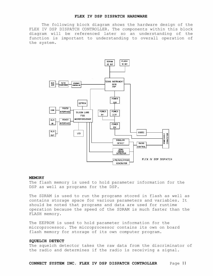
The following block diagram shows the hardware design of the
FLEX IV DSP DISPATCH CONTROLLER. The components within this block diagram will be referenced later so an understanding of the function is important to understanding to overall operation of the system.
MEMORY The flash memory is used to hold parameter information for the DSP as well as programs for the DSP. The SDRAM is used to run the programs stored in flash as well as contains storage space for various parameters and variables. It should be noted that programs and data are used for runtime operation because the speed of the SDRAM is much faster than the FLASH memory. The EEPROM is used to hold parameter information for the microprocessor. The microprocessor contains its own on board flash memory for storage of its own computer program. SQUELCH DETECT The squelch detector takes the raw data from the discriminator of the radio and determines if the radio is receiving a signal.
CONNECT SYSTEM INC. FLEX IV DSP DISPATCH CONTROLLER Page 12
ZERO CROSSING DETECTOR The zero crossing detector consist of a low pass filter with a cutoff of about 250 Hz followed by a circuit that determines zero crossing of the signal coming from the discriminator. The output of the circuitry goes to the microprocessor that is used to decode the signal to extract the CTCSS, DCS or LTR codes. LTR/DCS/CTCSS GENERATOR The various formats are generated using technologies very similar to that employed in the CSI legacy products such as the Models LT-4200 and TP-154. CODEC The codec is a 16 bit A/D converter and 16 bit D/A converter and is used to pass audio signals between the radio and the DSP. ETHERNET CONTROLLER The Ethernet Controller connects the IP network to the DSP. It is used to receive and transmit the VOIP and digital data. RS232 INTERFACE The RS232 Interface is used to transmit and receive RS232 digital data. RS422 INTERFACE The RS422 Interface is used to allow multiple FLEX IV DSP to communicate with each other to form a local area network to allow the system to work as an LTR controller. POWER SUPPLY The power supply consists of both switching and linear supplies to provide a simple and efficient power supply system to power the DSP, Microprocessor, and various interface components. TEXAS INSTRUMENTS 5510 DSP The Texas Instruments DSP contains one of the highest performing 16 bit DSP available. Its 200 MHz speed and large internal memory allows optimum performance for VoIP and other algorithms. SILICON LABS F120 MICROPROCESSOR The Silicon Labs F120 microprocessor is optimized for the encoding and decoding of CTCSS, DCS, and LTR formats. Its 100 MHz speed and single cycle instruction execution is one of the highest performing 8 bit microprocessor available.
CONNECT SYSTEM INC. FLEX IV DSP DISPATCH CONTROLLER Page 13
CONNECTING FLEX IV TO YOUR NETWORK
The RJ45 Jack connects directly to the users IP Network. The network can be a DSL connection to the public Internet, it can be a private network, it can be a Virtual Private Network (VPN), a wireless network such as Motorola’s Canopy, or any other network that is Ethernet compatible and supports the standard Internet protocol. There are four light emitting diodes on the board that are used for diagnostic purposes. They are as follows:
1. D15 is the RX led and it indicates the system is receiving packets from the IP network.
2. D5 is the TX led and it indicates we are sending IP packets to the IP network.
3. D14 is the LNK led and it indicates the cable is plugged into an active network.
4. D6 is the SEL led and it indicates the DSP is communicating with the Ethernet Controller.
CONNECT SYSTEM INC. FLEX IV DSP DISPATCH CONTROLLER Page 14
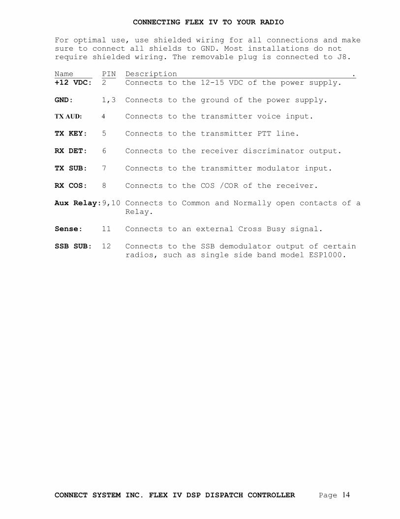
CONNECTING FLEX IV TO YOUR RADIO For optimal use, use shielded wiring for all connections and make sure to connect all shields to GND. Most installations do not require shielded wiring. The removable plug is connected to J8. Name PIN Description . +12 VDC: 2 Connects to the 12-15 VDC of the power supply. GND: 1,3 Connects to the ground of the power supply. TX AUD: 4 Connects to the transmitter voice input. TX KEY: 5 Connects to the transmitter PTT line. RX DET: 6 Connects to the receiver discriminator output. TX SUB: 7 Connects to the transmitter modulator input. RX COS: 8 Connects to the COS /COR of the receiver. Aux Relay:9,10 Connects to Common and Normally open contacts of a Relay. Sense: 11 Connects to an external Cross Busy signal. SSB SUB: 12 Connects to the SSB demodulator output of certain radios, such as single side band model ESP1000.
CONNECT SYSTEM INC. FLEX IV DSP DISPATCH CONTROLLER Page 15
INTERCONNECTING FLEX IV AND FLEX III-A
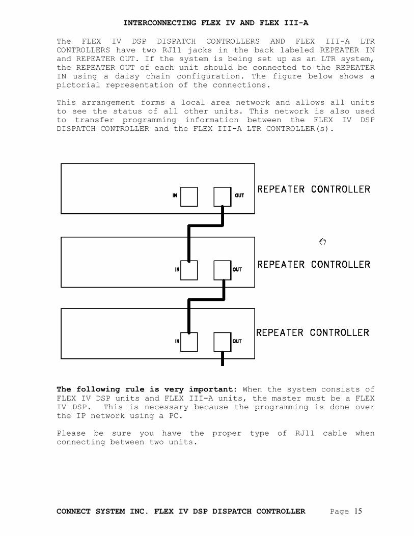
The FLEX IV DSP DISPATCH CONTROLLERS AND FLEX III-A LTR CONTROLLERS have two RJ11 jacks in the back labeled REPEATER IN and REPEATER OUT. If the system is being set up as an LTR system, the REPEATER OUT of each unit should be connected to the REPEATER IN using a daisy chain configuration. The figure below shows a pictorial representation of the connections. This arrangement forms a local area network and allows all units to see the status of all other units. This network is also used to transfer programming information between the FLEX IV DSP DISPATCH CONTROLLER and the FLEX III-A LTR CONTROLLER(s).
The following rule is very important: When the system consists of FLEX IV DSP units and FLEX III-A units, the master must be a FLEX IV DSP. This is necessary because the programming is done over the IP network using a PC. Please be sure you have the proper type of RJ11 cable when connecting between two units.
CONNECT SYSTEM INC. FLEX IV DSP DISPATCH CONTROLLER Page 16
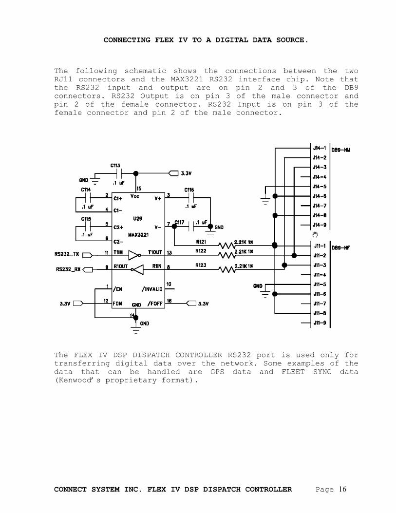
CONNECTING FLEX IV TO A DIGITAL DATA SOURCE. The following schematic shows the connections between the two RJ11 connectors and the MAX3221 RS232 interface chip. Note that the RS232 input and output are on pin 2 and 3 of the DB9 connectors. RS232 Output is on pin 3 of the male connector and pin 2 of the female connector. RS232 Input is on pin 3 of the female connector and pin 2 of the male connector.
The FLEX IV DSP DISPATCH CONTROLLER RS232 port is used only for transferring digital data over the network. Some examples of the data that can be handled are GPS data and FLEET SYNC data (Kenwood’s proprietary format).
CONNECT SYSTEM INC. FLEX IV DSP DISPATCH CONTROLLER Page 17
INTERNAL SCHEMATIC OF TX AUDIO
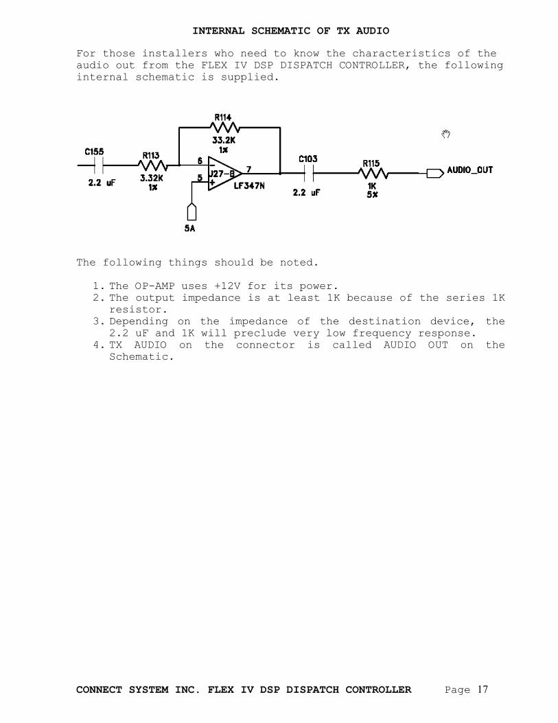
For those installers who need to know the characteristics of the audio out from the FLEX IV DSP DISPATCH CONTROLLER, the following internal schematic is supplied.
The following things should be noted.
1. The OP-AMP uses +12V for its power. 2. The output impedance is at least 1K because of the series 1K
resistor. 3. Depending on the impedance of the destination device, the
2.2 uF and 1K will preclude very low frequency response. 4. TX AUDIO on the connector is called AUDIO OUT on the
Schematic.
CONNECT SYSTEM INC. FLEX IV DSP DISPATCH CONTROLLER Page 18
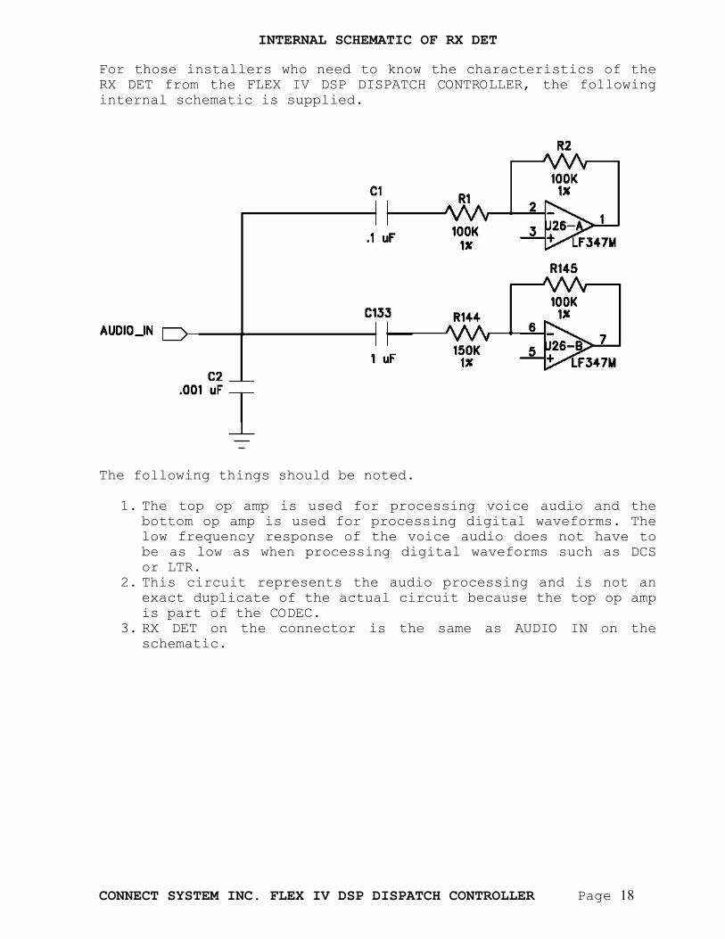
INTERNAL SCHEMATIC OF RX DET
For those installers who need to know the characteristics of the RX DET from the FLEX IV DSP DISPATCH CONTROLLER, the following internal schematic is supplied.
The following things should be noted.
1. The top op amp is used for processing voice audio and the bottom op amp is used for processing digital waveforms. The low frequency response of the voice audio does not have to be as low as when processing digital waveforms such as DCS or LTR.
2. This circuit represents the audio processing and is not an exact duplicate of the actual circuit because the top op amp is part of the CODEC.
3. RX DET on the connector is the same as AUDIO IN on the schematic.
CONNECT SYSTEM INC. FLEX IV DSP DISPATCH CONTROLLER Page 19
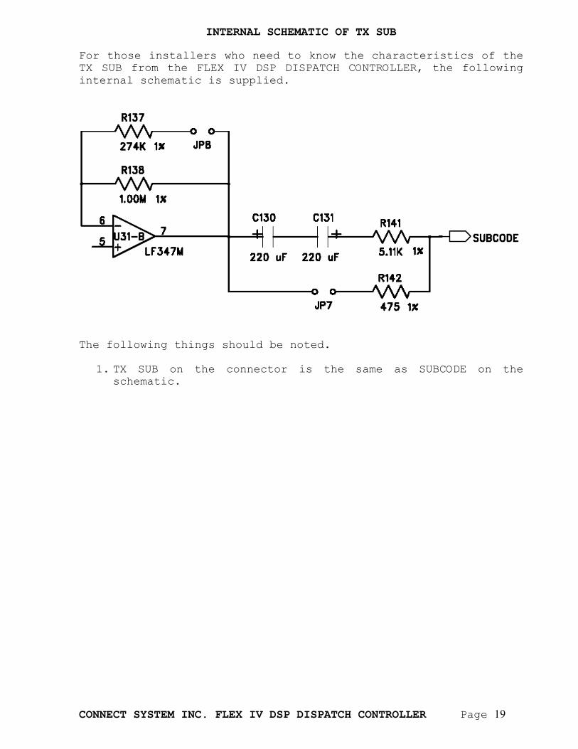
INTERNAL SCHEMATIC OF TX SUB
For those installers who need to know the characteristics of the TX SUB from the FLEX IV DSP DISPATCH CONTROLLER, the following internal schematic is supplied.
The following things should be noted.
1. TX SUB on the connector is the same as SUBCODE on the
schematic.
CONNECT SYSTEM INC. FLEX IV DSP DISPATCH CONTROLLER Page 20
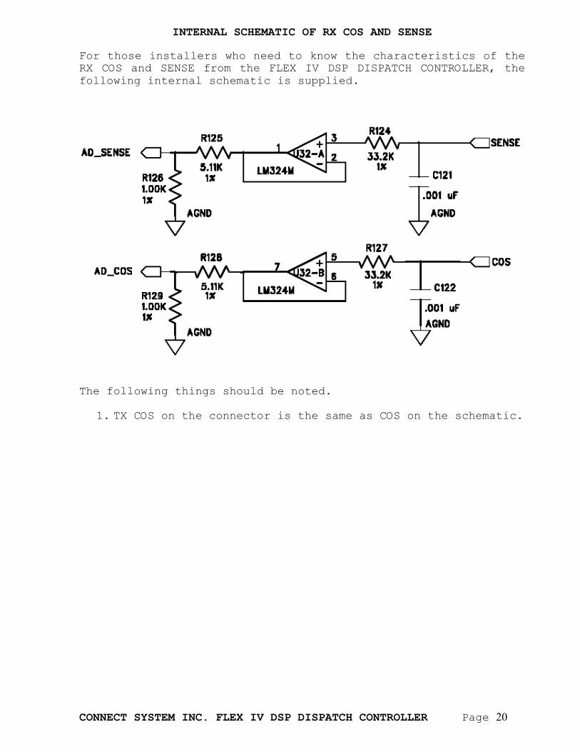
INTERNAL SCHEMATIC OF RX COS AND SENSE
For those installers who need to know the characteristics of the RX COS and SENSE from the FLEX IV DSP DISPATCH CONTROLLER, the following internal schematic is supplied.
The following things should be noted.
1. TX COS on the connector is the same as COS on the schematic.
CONNECT SYSTEM INC. FLEX IV DSP DISPATCH CONTROLLER Page 21
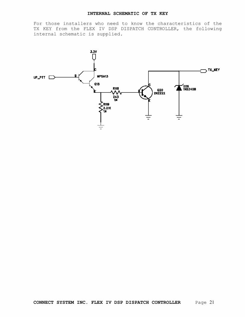
INTERNAL SCHEMATIC OF TX KEY
For those installers who need to know the characteristics of the TX KEY from the FLEX IV DSP DISPATCH CONTROLLER, the following internal schematic is supplied.
CONNECT SYSTEM INC. FLEX IV DSP DISPATCH CONTROLLER Page 22
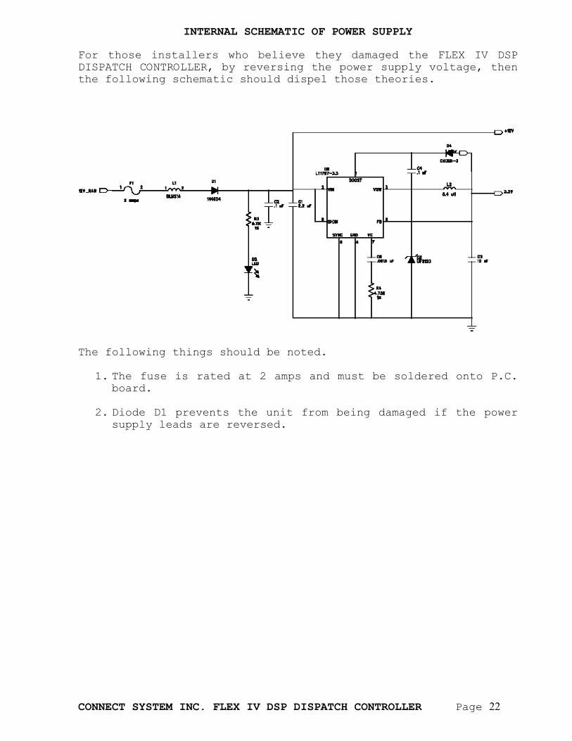
INTERNAL SCHEMATIC OF POWER SUPPLY
For those installers who believe they damaged the FLEX IV DSP DISPATCH CONTROLLER, by reversing the power supply voltage, then the following schematic should dispel those theories.
The following things should be noted.
1. The fuse is rated at 2 amps and must be soldered onto P.C.
board.
2. Diode D1 prevents the unit from being damaged if the power supply leads are reversed.
CONNECT SYSTEM INC. FLEX IV DSP DISPATCH CONTROLLER Page 23
LEVEL CONTROLS FOR THE FLEX IV There are five POTS on the FLEX IV DSP DISPATCH CONTROLLER that are accessible by removing the front plate. The plate can be removed without removing the unit from the rack. CONTRAST The CONTRAST pot is used to adjust the contrast on the LCD. CTCSS The CTCSS pot is used to adjust the level going to the TX SUB point on the removable connector. DCS/LTR The DCS/LTR pot is used to adjust the level going to the TX SUB point on the removable connector. SQUELCH The SQUELCH pot is used to adjust the level it takes for squelch detector to indicate it’s receiving a signal from the mobile or portable radio. PREAMP The preamp is used to adjust the RX IN level going to the CTCSS, DCS, and LTR decoders as well as the audio going to the CODEC. This adjustment is normally set so the data led inside the unit (D27) is just starting to blink. The audio out level is controlled entirely by programming the system. The audio in level is controlled both by the PREAMP pot as well as programming the system.
CONNECT SYSTEM INC. FLEX IV DSP DISPATCH CONTROLLER Page 24
SELECTED CONNECTORS AND JUMPERS J1 is used as a JTAG connector to the DSP. If the system crashed, it might be necessary to reload the DSP program into the FLASH memory through that connector. The method is beyond the capability of most radio dealers so no information will be given on the techniques. J12 is used as a JTAG connector to the microprocessor. If the system crashed, it might be necessary to reload the program into the FLASH memory of the microprocessor through that connector. This is accomplished by the CSI Model FLEX-M, which is a low cost RS232 to JTAG converter. J13 is set for diagnostic modes and testing modes. There are 7 jumpers J13-1 to J13-7 (from right to left). For Flex IV units as network LTR controllers, the settings are as follows. J13-7 is used to set the unit in diagnostic mode 3. J13-6 is the factory test mode. J13-5 is the factory test mode. J13-4 is the factory test mode. J13-3 is used to set the unit in diagnostic mode 1. J13-2 is used to set the unit in diagnostic mode 2. J13-1 J13-4 is the factory test mode. JP6 when inserted will allow the SSB capability of some radios. JP7 when inserted will allow the TX SUB to be directly coupled instead of capacitive coupled. JP8 when inserted, the gain of the TX SUB final amp has a gain of 2.5 and when removed has a gain of 10. JP9 when inserted, the gain of the preamp is 10 and when removed has a gain of 100. JP10 should be inserted when using radios with SSB capability and removed otherwise. JP11 when inserted provides a 619 ohm termination resistor across the RS485 interface and when not inserted, there is no termination resistor.
CONNECT SYSTEM INC. FLEX IV DSP DISPATCH CONTROLLER Page 25
OVERVIEW
The Flex IV Series Networking LTR Controller and Community Tone Panel is a sophisticated networking, dispatch only, trunking Repeater Manager (Controller) and Community Tone Panel for use on LTR trunked repeater systems. The Flex IV Series LTR Controller and Community Tone Panel may not be used with any other makes of LTR controllers including Connect Systems Inc. models LT-4200 or LT-4900. The Flex IV Series LTR Controller and Community Tone Panel provides up to 250 LTR USER ID’s per repeater, 112 DCS users and 51 CTCSS users. There may be up to 20 repeaters per system. The Flex IV Series LTR Controller and Community Tone Panel “talks” to the other controllers on the system using a proprietary RS485 Bus Protocol that transfers both LTR data and Programming data. Other panels use two separate busses. The CSI panels with a front panel LCD display keeps you totally informed about repeater and system status while you are at the repeater site. User ID and other useful data are constantly displayed. Another unique feature is the ability to set levels remotely. Most other panels require you to be at the site and take the repeater out of the rack. This panel allows you to change most levels from thousands of miles away via the Internet.
A CLOSER LOOK
LTR BUS FOR THE FLEX IV AND FLEX III-A CONTROLLERS Select one of the FLEX IV’s as a master. All other FLEX IV’s and FLEX III-A’s are slaves. Each FLEX IV should be programmed over the IP network individually. The FLEX III-A’s will be programmed from the master FLEX IV via cloning. Daisy chain connections are used for the LTR bus. Use the wires provided by CSI to connect the RPTR BUS of each Flex IV or FLEX III-A LTR repeater controller to the next FLEX IV or FLEX III-A repeater controller.
INSTALLATION PROCEDURES
Each FLEX IV controller shipped by CSI has the default settings as follows: IP address: 192.168.1.80 subnet mask: 255.255.255.0 gateway : 192.168.1.254 repeater number: 1 site number: 1.
CONNECT SYSTEM INC. FLEX IV DSP DISPATCH CONTROLLER Page 26
1. Assign each FLEX IV controller a new IP address, a site number and a repeater number. 2. Select one of the Flex IV units as the master at each site. Only one master is allowed at each site. 3. Use FlexCtrl IV.exe to create the .ini file which contains the parameters for each Flex IV unit. 4. Run Flex_PC.exe. Use option D (Load Program Data into Flex IV) to load all parameters into Flex IV. 5. Test each Flex IV unit to make sure it works with its repeater. 6. If you have Flex III-A in the system, you must program the Flex III-A units as slaves and put the parameters for Flex III-A units into the master. 7. Connect the LTR Bus from the master to all slaves at each site. If you are still having problems, call Connect Systems Inc. at 1-800-545-1349 for technical assistance.
CONNECT SYSTEM INC. FLEX IV DSP DISPATCH CONTROLLER Page 27
DIAGNOSTIC MODES
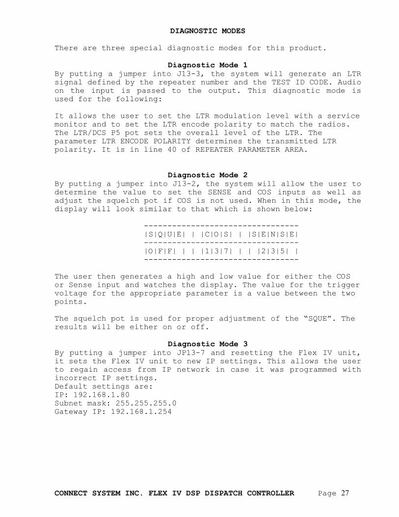
There are three special diagnostic modes for this product.
Diagnostic Mode 1 By putting a jumper into J13-3, the system will generate an LTR signal defined by the repeater number and the TEST ID CODE. Audio on the input is passed to the output. This diagnostic mode is used for the following: It allows the user to set the LTR modulation level with a service monitor and to set the LTR encode polarity to match the radios. The LTR/DCS P5 pot sets the overall level of the LTR. The parameter LTR ENCODE POLARITY determines the transmitted LTR polarity. It is in line 40 of REPEATER PARAMETER AREA.
Diagnostic Mode 2 By putting a jumper into J13-2, the system will allow the user to determine the value to set the SENSE and COS inputs as well as adjust the squelch pot if COS is not used. When in this mode, the display will look similar to that which is shown below: --------------------------------- |S|Q|U|E| | |C|O|S| | |S|E|N|S|E| --------------------------------- |O|F|F| | | |1|3|7| | | |2|3|5| | --------------------------------- The user then generates a high and low value for either the COS or Sense input and watches the display. The value for the trigger voltage for the appropriate parameter is a value between the two points. The squelch pot is used for proper adjustment of the “SQUE”. The results will be either on or off.
Diagnostic Mode 3 By putting a jumper into JP13-7 and resetting the Flex IV unit, it sets the Flex IV unit to new IP settings. This allows the user to regain access from IP network in case it was programmed with incorrect IP settings. Default settings are: IP: 192.168.1.80 Subnet mask: 255.255.255.0 Gateway IP: 192.168.1.254
CONNECT SYSTEM INC. FLEX IV DSP DISPATCH CONTROLLER Page 28
IMPORTANT NOTE In the following sections, we provide full details for each parameter in the FLEX IV setup. For ease of setup of these parameters, refer to the program FlexCtrl.exe on the Program Disc supplied by CSI.
GLOBAL PROGRAMMING AREA
STORED IN INI FILE REPEATER NUMBER *0000#01#MM# MM ranges from 1 to 20 Default = 1 In an LTR system, there are up to 20 repeaters at a given site. Each repeater is a unique number from 1 through 20. If the controllers are using only CTCSS or DCS, then this parameter has no meaning. SITE NUMBER *0000#02#MM# MM ranges from 1 to 99 Default = 1 This networking system supports up to 99 different sites. Each site can have up to 20 repeaters. There is nothing preventing the system designer from having a single physical site having multiple site numbers.
CONNECT SYSTEM INC. FLEX IV DSP DISPATCH CONTROLLER Page 29
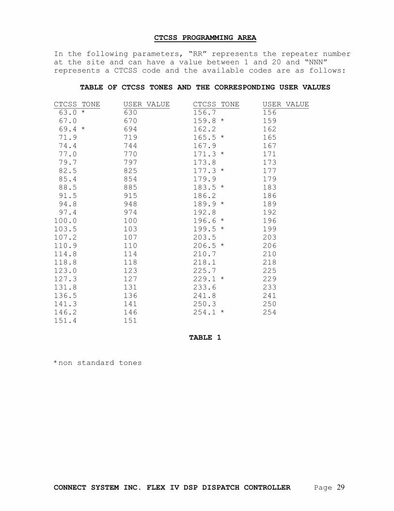
CTCSS PROGRAMMING AREA In the following parameters, “RR” represents the repeater number at the site and can have a value between 1 and 20 and “NNN” represents a CTCSS code and the available codes are as follows:
TABLE OF CTCSS TONES AND THE CORRESPONDING USER VALUES CTCSS TONE USER VALUE CTCSS TONE USER VALUE 63.0 * 630 156.7 156 67.0 670 159.8 * 159 69.4 * 694 162.2 162 71.9 719 165.5 * 165 74.4 744 167.9 167 77.0 770 171.3 * 171 79.7 797 173.8 173 82.5 825 177.3 * 177 85.4 854 179.9 179 88.5 885 183.5 * 183 91.5 915 186.2 186 94.8 948 189.9 * 189 97.4 974 192.8 192 100.0 100 196.6 * 196 103.5 103 199.5 * 199 107.2 107 203.5 203 110.9 110 206.5 * 206 114.8 114 210.7 210 118.8 118 218.1 218 123.0 123 225.7 225 127.3 127 229.1 * 229 131.8 131 233.6 233 136.5 136 241.8 241 141.3 141 250.3 250 146.2 146 254.1 * 254 151.4 151
TABLE 1 *non standard tones

CONNECT SYSTEM INC. FLEX IV DSP DISPATCH CONTROLLER Page 30
CONNECT SYSTEM INC. FLEX IV DSP DISPATCH CONTROLLER Page 31
STORED IN INI FILE
COURTESY BEEP *10RR#NNN#01#J# J = 1 = Enabled, J = 0 = Disabled Default = 0 The courtesy beep is used to indicate to the user that the other party released its PTT. The courtesy beep happens immediately after the COS or internal squelch goes from a true condition to a false condition. This beep indicates to the other party that they can start speaking. In a CTCSS/DCS system, the beep happens during the hang time. In an LTR system there is no hang time so it happens immediately after the turn off code is received. CTCSS DURING HANG TIME
*10RR#NNN#02#J# J = 1 = Enabled, J = 0 = Disabled Default = 1 If the CTCSS during hang time is enabled, the CTCSS continues during hang time even though the user has turned off their radio. If the parameter is disabled, then the CTCSS turns off immediately after the systems goes into hang time. SUBSCRIBER ENABLE/DISABLE
*10RR#NNN#03#J# J = 1 = Enabled, J = 0 = Disabled Default = 0 If subscriber enable/disable is enabled, and the specified tone is received, the system will repeat this conversation on the local repeater. If the feature is disabled, then the conversation will not be repeated. This feature is independent of the network mode. RESERVE TONE
*10RR#NNN#04#J# J = 1 = Enabled, J = 0 = Disabled Default = 0 If a subscriber tone is turned off and reserve tone is enabled, the repeater will come up, but no audio will pass. Beeps indicate reserve tone is active. This feature is typically used for reserving a tone or code on a radio channel without actually using the channel. It prevents nearby repeater operators from using the reserved tone on the same channel. NETWORK MODE
*10RR#NNN#05#J# J = 1 = Enabled, J = 0 = Disabled Default = 1 If the network mode is enabled, then this tone will setup a network call. The actual destination addresses are defined in the Global IP sections of the programming. This feature is independent of the subscriber enable/disable parameter. If this feature is enabled but the subscriber enable/disable feature is disabled, then the output of the VoIP channel will go to the transmitter of the attached repeater and the receiver audio will be sent using VoIP over the network. The receiver from this repeater will not be sent over the transmitter thereby allowing a
CONNECT SYSTEM INC. FLEX IV DSP DISPATCH CONTROLLER Page 32
minimum amount of privacy. If this feature is disabled, then a network call will not be made. PRIORITY LEVEL
*10RR#NNN#07#M# M = 0 – 3 Default = 0 In certain applications, it might be desired to allow certain users to have priority over other users. As an example, the chief of police might want the authority to send a message over all the channels in the network, even if they are currently in use. In the current version, only priority level 0 is used. Priority level 0 does not give priority over any other user SITE 0 TELCO TYPE
*10RR#NNN#08#M# M = 0 – 3 Default = 0 M = 0: Telephone Line not used M = 1: Phone Patch, use speed dial M = 2: Phone Patch, manual dial M = 3: Ring Local Telephone This feature is not supported in the FLEX IV DSP-D DISPATCH CONTROLLER. SITE 0 TELEPHONE NUMBER
*10RR#NNN#09#MMMMMMMMMMMMMMMM# DEFAULT = ALL BLANKS Telephone Number is the speed dial number. The allowable characters for telephone numbers are 0 – 9, *, #, W, T, and blank. “T” is to wait for dial tone and “W” is to wait one second. This feature is not supported in the FLEX IV DSP-D DISPATCH CONTROLLER. SITE 1 REPEATER NUMBER
*10RR#NNN#10#MMNN# MM = SITE = 0 – 99 Default = 00 NN = REPEATER NUMBER = 0 – 20 Default = 00 The repeater number is a number associated with the Global IP table and is used as a shortcut to the full IP address. If the value of the repeater number is 0000, then site 1 will not be used for this particular tone. SITE 1 CODE TYPE
*10RR#NNN#11#M# M = 0 – 5 Default = 0 Code Type is a selectable field indicating if the code at the destination is NONE(0), CTCSS(1), DCS(2), LTR(3), P25(4), or OTHER(5). SITE 1 CODE
*10RR#NNN#12#MMMMMM# MMMMMM = CTCSS,DCS,LTR,P25,OTHER CODE Default = 000000 This is a code corresponding to the code type that is used to tell the remote site how to set up the channel. If the number of characters required by the code is less than 6, then the code is
CONNECT SYSTEM INC. FLEX IV DSP DISPATCH CONTROLLER Page 33
left justified and zeros are filled to the right. As an example, if the DCS code is 023, then MMMMMM = 023000. SITE 1 TELCO TYPE
*10RR#NNN#13#M# M = 0 – 3 Default = 0 M = 0: Telephone Line not used M = 1: Phone Patch, use speed dial M = 2: Phone Patch, manual dial M = 3: Ring Local Telephone The telephone line used with this parameter is actually the telephone line at the remote site. This implies that the destination FLEX IV CONTROLLER at the remote site must be the Public Safety version. This allows the system to make local telephone calls even though the originator of the telephone might be on another continent. SITE 1 TELEPHONE NUMBER
*10RR#NNN#14#MMMMMMMMMMMMMMMM# DEFAULT = ALL BLANKS Telephone Number is the speed dial number. The allowable characters for telephone numbers are 0 – 9, *, #, W, T, and blank. “T” is wait for dial tone and “W” is wait one second. SITE 2 REPEATER NUMBER
*10RR#NNN#15#MMNN# MM = SITE = 0 – 99 Default = 00 NN = REPEATER NUMBER = 0 – 20 Default = 00 The repeater number is a number associated with the Global IP table and is used as a shortcut to the full IP address. If the value of the repeater number is 0000, then site 2 will not be used for this particular tone. SITE 2 CODE TYPE
*10RR#NNN#16#M# M = 0 – 5 Default = 0 Code Type is a selectable field indicating if the code at the destination is NONE(0), CTCSS(1), DCS(2), LTR(3), P25(4), or OTHER(5). SITE 2 CODE
*10RR#NNN#17#MMMMMM# MMMMMM = CTCSS,DCS,LTR,P25,OTHER CODE Default = 000000 This is a code corresponding to the code type that is used to tell the remote site how to set up the channel. If the number of characters required by the code is less than 6, then the code is left justified and zeros are filled to the right. As an example, if the DCS code is 023, then MMMMMM = 023000. SITE 2 TELCO TYPE
*10RR#NNN#18#M# M = 0 – 3 Default = 0 M = 0: Telephone Line not used M = 1: Phone Patch, use speed dial
CONNECT SYSTEM INC. FLEX IV DSP DISPATCH CONTROLLER Page 34
M = 2: Phone Patch, manual dial M = 3: Ring Local Telephone The telephone line used with this parameter is actually the telephone line at the remote site. This implies that the destination FLEX IV CONTROLLER at the remote site must be the Public Safety version. This allows the system to make local telephone calls even though the originator of the telephone might be on another continent. SITE 2 TELEPHONE NUMBER
*10RR#NNN#19#MMMMMMMMMMMMMMMM# DEFAULT = ALL BLANKS Telephone Number is the speed dial number. The allowable characters for telephone numbers are 0 – 9, *, #, W, T, and blank. “T” is wait for dial tone and “W” is wait one second. SITE 3 REPEATER NUMBER
*10RR#NNN#20#MMNN# MM = SITE = 0 – 99 Default = 00 NN = REPEATER NUMBER = 0 – 20 Default = 00 The repeater number is a number associated with the Global IP table and is used as a shortcut to the full IP address. If the value of the repeater number is 0000, then site 1 will not be used for this particular tone. SITE 3 CODE TYPE
*10RR#NNN#21#M# M = 0 – 5 Default = 0 Code Type is a selectable field indicating if the code at the destination is NONE(0), CTCSS(1), DCS(2), LTR(3), P25(4), or OTHER(5). SITE 3 CODE
*10RR#NNN#22#MMMMMM# MMMMMM = CTCSS,DCS,LTR,P25,OTHER CODE Default = 000000 This is a code corresponding to the code type that is used to tell the remote site how to set up the channel. If the number of characters required by the code is less than 6, then the code is left justified and zeros are filled to the right. As an example, if the DCS code is 023, then MMMMMM = 023000. SITE 3 TELCO TYPE
*10RR#NNN#23#M# M = 0 – 3 Default = 0 M = 0: Telephone Line not used M = 1: Phone Patch, use speed dial M = 2: Phone Patch, manual dial M = 3: Ring Local Telephone The telephone line used with this parameter is actually the telephone line at the remote site. This implies that the destination FLEX IV CONTROLLER at the remote site must be the Public Safety version. This allows the system to make local telephone calls even though the originator of the telephone might be on another continent.
CONNECT SYSTEM INC. FLEX IV DSP DISPATCH CONTROLLER Page 35
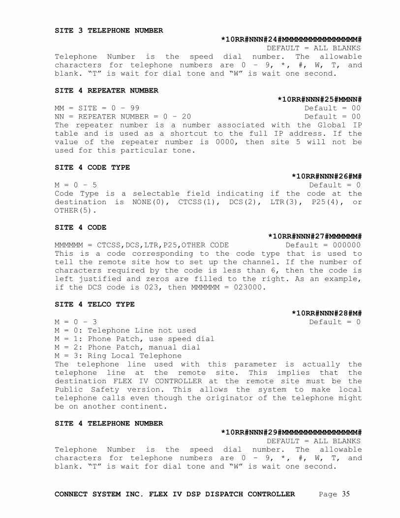
SITE 3 TELEPHONE NUMBER
*10RR#NNN#24#MMMMMMMMMMMMMMMM# DEFAULT = ALL BLANKS Telephone Number is the speed dial number. The allowable characters for telephone numbers are 0 – 9, *, #, W, T, and blank. “T” is wait for dial tone and “W” is wait one second. SITE 4 REPEATER NUMBER
*10RR#NNN#25#MMNN# MM = SITE = 0 – 99 Default = 00 NN = REPEATER NUMBER = 0 – 20 Default = 00 The repeater number is a number associated with the Global IP table and is used as a shortcut to the full IP address. If the value of the repeater number is 0000, then site 5 will not be used for this particular tone. SITE 4 CODE TYPE
*10RR#NNN#26#M# M = 0 – 5 Default = 0 Code Type is a selectable field indicating if the code at the destination is NONE(0), CTCSS(1), DCS(2), LTR(3), P25(4), or OTHER(5). SITE 4 CODE
*10RR#NNN#27#MMMMMM# MMMMMM = CTCSS,DCS,LTR,P25,OTHER CODE Default = 000000 This is a code corresponding to the code type that is used to tell the remote site how to set up the channel. If the number of characters required by the code is less than 6, then the code is left justified and zeros are filled to the right. As an example, if the DCS code is 023, then MMMMMM = 023000. SITE 4 TELCO TYPE
*10RR#NNN#28#M# M = 0 – 3 Default = 0 M = 0: Telephone Line not used M = 1: Phone Patch, use speed dial M = 2: Phone Patch, manual dial M = 3: Ring Local Telephone The telephone line used with this parameter is actually the telephone line at the remote site. This implies that the destination FLEX IV CONTROLLER at the remote site must be the Public Safety version. This allows the system to make local telephone calls even though the originator of the telephone might be on another continent. SITE 4 TELEPHONE NUMBER
*10RR#NNN#29#MMMMMMMMMMMMMMMM# DEFAULT = ALL BLANKS Telephone Number is the speed dial number. The allowable characters for telephone numbers are 0 – 9, *, #, W, T, and blank. “T” is wait for dial tone and “W” is wait one second.

CONNECT SYSTEM INC. FLEX IV DSP DISPATCH CONTROLLER Page 36
SITE 5 REPEATER NUMBER *10RR#NNN#30#MMNN#
MM = SITE = 0 – 99 Default = 00 NN = REPEATER NUMBER = 0 – 20 Default = 00 The repeater number is a number associated with the Global IP table and is used as a shortcut to the full IP address. If the value of the repeater number is 0000, then site 5 will not be used for this particular tone. SITE 5 CODE TYPE
*10RR#NNN#31#M# M = 0 – 5 Default = 0 Code Type is a selectable field indicating if the code at the destination is NONE(0), CTCSS(1), DCS(2), LTR(3), P25(4), or OTHER(5). SITE 5 CODE
*10RR#NNN#32#MMMMMM# MMMMMM = CTCSS,DCS,LTR,P25,OTHER CODE Default = 000000 This is a code corresponding to the code type that is used to tell the remote site how to set up the channel. If the number of characters required by the code is less than 6, then the code is left justified and zeros are filled to the right. As an example, if the DCS code is 023, then MMMMMM = 023000. SITE 5 TELCO TYPE
*10RR#NNN#33#M# M = 0 – 3 Default = 0 M = 0: Telephone Line not used M = 1: Phone Patch, use speed dial M = 2: Phone Patch, manual dial M = 3: Ring Local Telephone The telephone line used with this parameter is actually the telephone line at the remote site. This implies that the destination FLEX IV CONTROLLER at the remote site must be the Public Safety version. This allows the system to make local telephone calls even though the originator of the telephone might be on another continent. SITE 5 TELEPHONE NUMBER
*10RR#NNN#34#MMMMMMMMMMMMMMMM# DEFAULT = ALL BLANKS Telephone Number is the speed dial number. The allowable characters for telephone numbers are 0 – 9, *, #, W, T, and blank. “T” is wait for dial tone and “W” is wait one second. SITE 6 REPEATER NUMBER
*10RR#NNN#35#MMNN# MM = SITE = 0 – 99 Default = 00 NN = REPEATER NUMBER = 0 – 20 Default = 00 The repeater number is a number associated with the Global IP table and is used as a shortcut to the full IP address. If the value of the repeater number is 0000, then site 6 will not be used for this particular tone.
CONNECT SYSTEM INC. FLEX IV DSP DISPATCH CONTROLLER Page 37
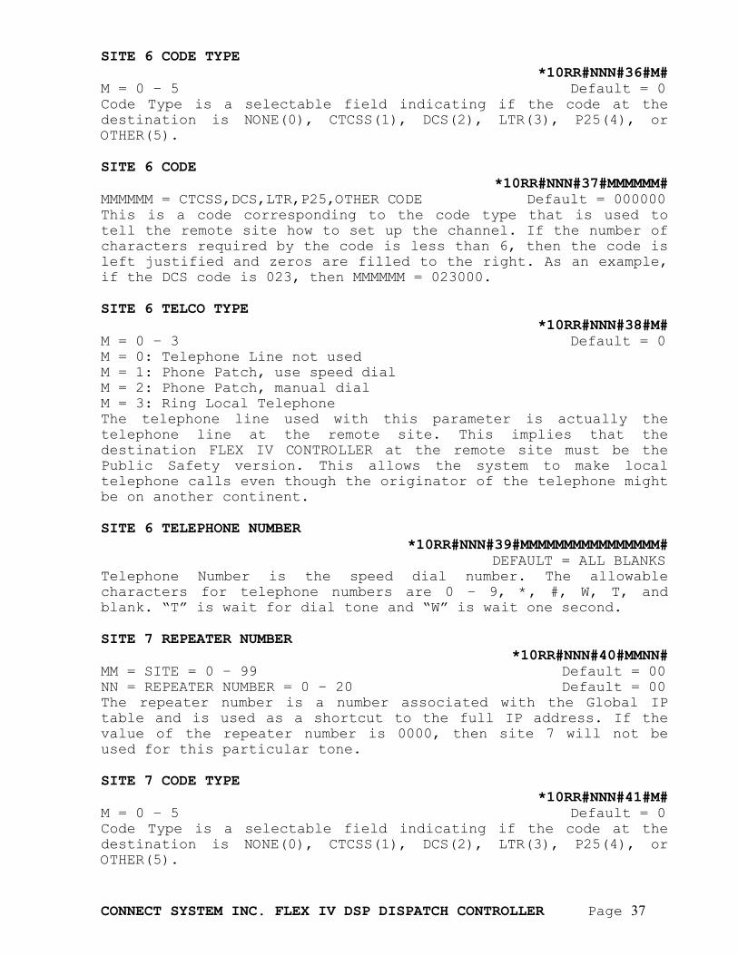
SITE 6 CODE TYPE
*10RR#NNN#36#M# M = 0 – 5 Default = 0 Code Type is a selectable field indicating if the code at the destination is NONE(0), CTCSS(1), DCS(2), LTR(3), P25(4), or OTHER(5). SITE 6 CODE
*10RR#NNN#37#MMMMMM# MMMMMM = CTCSS,DCS,LTR,P25,OTHER CODE Default = 000000 This is a code corresponding to the code type that is used to tell the remote site how to set up the channel. If the number of characters required by the code is less than 6, then the code is left justified and zeros are filled to the right. As an example, if the DCS code is 023, then MMMMMM = 023000. SITE 6 TELCO TYPE
*10RR#NNN#38#M# M = 0 – 3 Default = 0 M = 0: Telephone Line not used M = 1: Phone Patch, use speed dial M = 2: Phone Patch, manual dial M = 3: Ring Local Telephone The telephone line used with this parameter is actually the telephone line at the remote site. This implies that the destination FLEX IV CONTROLLER at the remote site must be the Public Safety version. This allows the system to make local telephone calls even though the originator of the telephone might be on another continent. SITE 6 TELEPHONE NUMBER
*10RR#NNN#39#MMMMMMMMMMMMMMMM# DEFAULT = ALL BLANKS Telephone Number is the speed dial number. The allowable characters for telephone numbers are 0 – 9, *, #, W, T, and blank. “T” is wait for dial tone and “W” is wait one second. SITE 7 REPEATER NUMBER
*10RR#NNN#40#MMNN# MM = SITE = 0 – 99 Default = 00 NN = REPEATER NUMBER = 0 – 20 Default = 00 The repeater number is a number associated with the Global IP table and is used as a shortcut to the full IP address. If the value of the repeater number is 0000, then site 7 will not be used for this particular tone. SITE 7 CODE TYPE
*10RR#NNN#41#M# M = 0 – 5 Default = 0 Code Type is a selectable field indicating if the code at the destination is NONE(0), CTCSS(1), DCS(2), LTR(3), P25(4), or OTHER(5).
CONNECT SYSTEM INC. FLEX IV DSP DISPATCH CONTROLLER Page 38
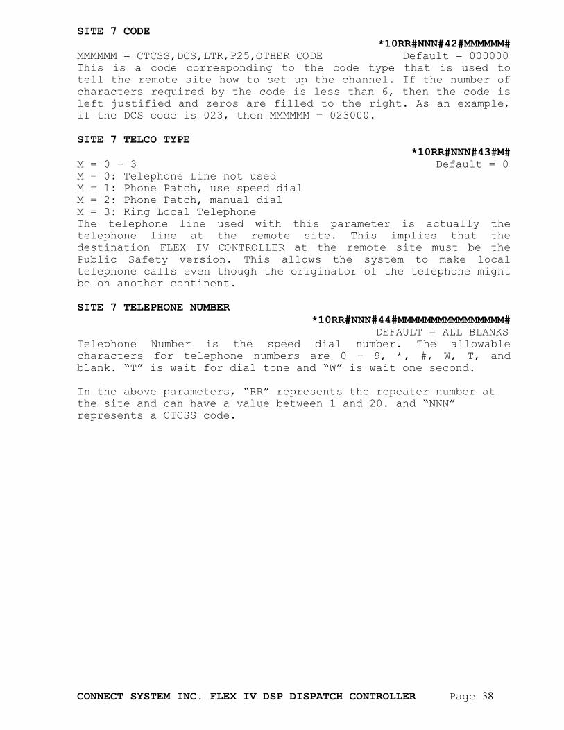
SITE 7 CODE *10RR#NNN#42#MMMMMM#
MMMMMM = CTCSS,DCS,LTR,P25,OTHER CODE Default = 000000 This is a code corresponding to the code type that is used to tell the remote site how to set up the channel. If the number of characters required by the code is less than 6, then the code is left justified and zeros are filled to the right. As an example, if the DCS code is 023, then MMMMMM = 023000. SITE 7 TELCO TYPE
*10RR#NNN#43#M# M = 0 – 3 Default = 0 M = 0: Telephone Line not used M = 1: Phone Patch, use speed dial M = 2: Phone Patch, manual dial M = 3: Ring Local Telephone The telephone line used with this parameter is actually the telephone line at the remote site. This implies that the destination FLEX IV CONTROLLER at the remote site must be the Public Safety version. This allows the system to make local telephone calls even though the originator of the telephone might be on another continent. SITE 7 TELEPHONE NUMBER
*10RR#NNN#44#MMMMMMMMMMMMMMMM# DEFAULT = ALL BLANKS Telephone Number is the speed dial number. The allowable characters for telephone numbers are 0 – 9, *, #, W, T, and blank. “T” is wait for dial tone and “W” is wait one second. In the above parameters, “RR” represents the repeater number at the site and can have a value between 1 and 20. and “NNN” represents a CTCSS code.
CONNECT SYSTEM INC. FLEX IV DSP DISPATCH CONTROLLER Page 39
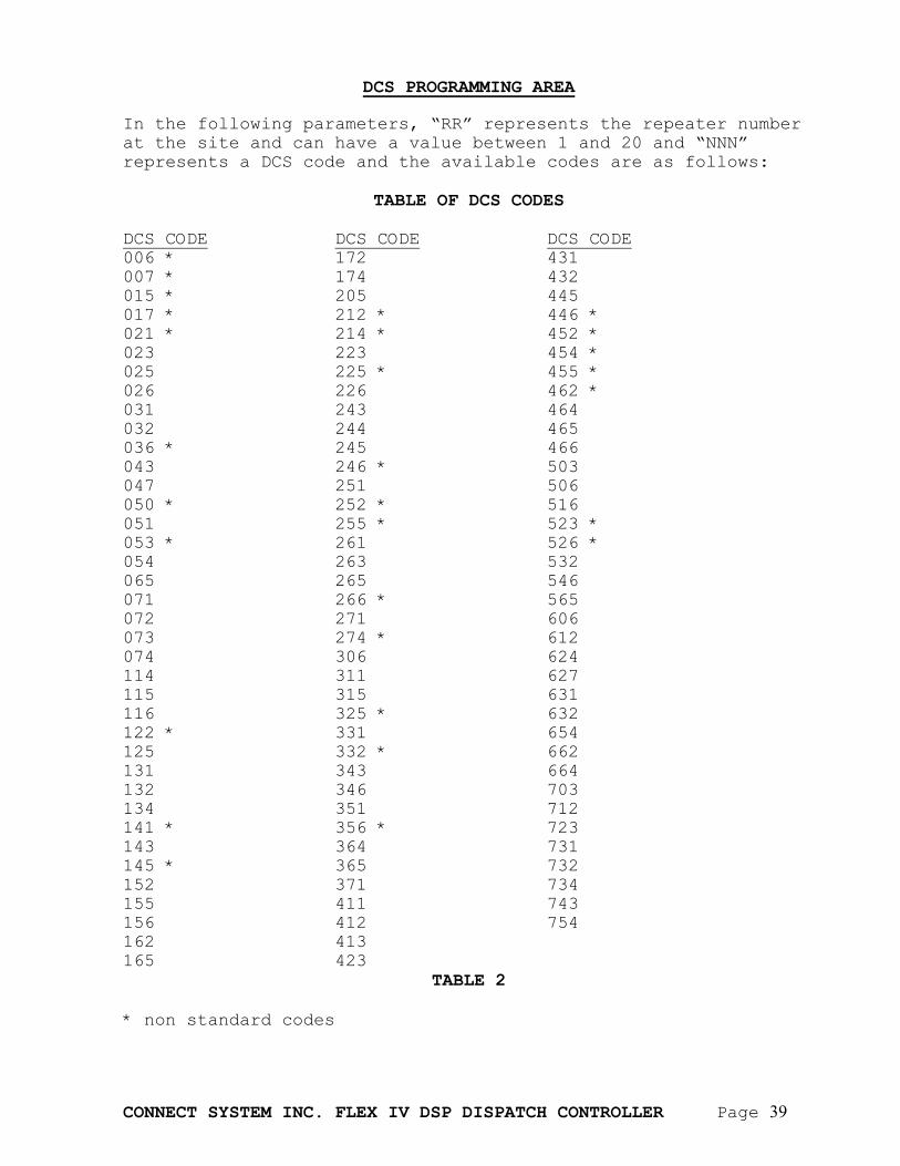
DCS PROGRAMMING AREA In the following parameters, “RR” represents the repeater number at the site and can have a value between 1 and 20 and “NNN” represents a DCS code and the available codes are as follows:
TABLE OF DCS CODES DCS CODE DCS CODE DCS CODE 006 * 172 431 007 * 174 432 015 * 205 445 017 * 212 * 446 * 021 * 214 * 452 * 023 223 454 * 025 225 * 455 * 026 226 462 * 031 243 464 032 244 465 036 * 245 466 043 246 * 503 047 251 506 050 * 252 * 516 051 255 * 523 * 053 * 261 526 * 054 263 532 065 265 546 071 266 * 565 072 271 606 073 274 * 612 074 306 624 114 311 627 115 315 631 116 325 * 632 122 * 331 654 125 332 * 662 131 343 664 132 346 703 134 351 712 141 * 356 * 723 143 364 731 145 * 365 732 152 371 734 155 411 743 156 412 754 162 413 165 423
TABLE 2
* non standard codes
CONNECT SYSTEM INC. FLEX IV DSP DISPATCH CONTROLLER Page 40
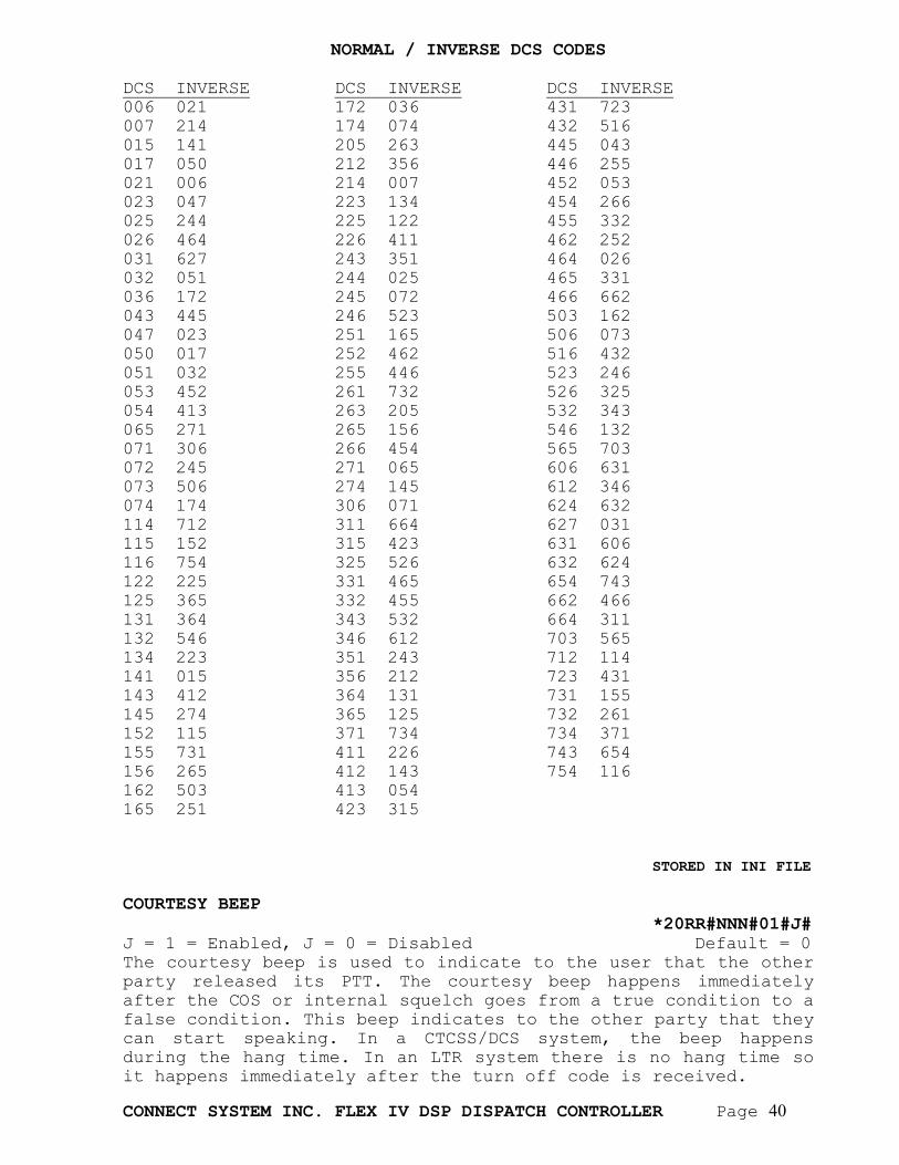
NORMAL / INVERSE DCS CODES DCS INVERSE DCS INVERSE DCS INVERSE 006 021 172 036 431 723 007 214 174 074 432 516 015 141 205 263 445 043 017 050 212 356 446 255 021 006 214 007 452 053 023 047 223 134 454 266 025 244 225 122 455 332 026 464 226 411 462 252 031 627 243 351 464 026 032 051 244 025 465 331 036 172 245 072 466 662 043 445 246 523 503 162 047 023 251 165 506 073 050 017 252 462 516 432 051 032 255 446 523 246 053 452 261 732 526 325 054 413 263 205 532 343 065 271 265 156 546 132 071 306 266 454 565 703 072 245 271 065 606 631 073 506 274 145 612 346 074 174 306 071 624 632 114 712 311 664 627 031 115 152 315 423 631 606 116 754 325 526 632 624 122 225 331 465 654 743 125 365 332 455 662 466 131 364 343 532 664 311 132 546 346 612 703 565 134 223 351 243 712 114 141 015 356 212 723 431 143 412 364 131 731 155 145 274 365 125 732 261 152 115 371 734 734 371 155 731 411 226 743 654 156 265 412 143 754 116 162 503 413 054 165 251 423 315
STORED IN INI FILE
COURTESY BEEP *20RR#NNN#01#J# J = 1 = Enabled, J = 0 = Disabled Default = 0 The courtesy beep is used to indicate to the user that the other party released its PTT. The courtesy beep happens immediately after the COS or internal squelch goes from a true condition to a false condition. This beep indicates to the other party that they can start speaking. In a CTCSS/DCS system, the beep happens during the hang time. In an LTR system there is no hang time so it happens immediately after the turn off code is received.
CONNECT SYSTEM INC. FLEX IV DSP DISPATCH CONTROLLER Page 41
DCS DURING HANG TIME
*20RR#NNN#02#J# J = 1 = Enabled, J = 0 = Disabled Default = 1 If the DCS during hang time is enabled, the DCS continues during hang time even though the user has turned off their radio. If the parameter is disabled, then the DCS turns off immediately after the systems goes into hang time. SUBSCRIBER ENABLE/DISABLE
*20RR#NNN#03#J# J = 1 = Enabled, J = 0 = Disabled Default = 0 If subscriber enable/disable is enabled, and the specified code is received, the system will repeat this conversation on the local repeater. If the feature is disabled, then the conversation will not be repeated. This feature is independent of the network mode. RESERVE CODE
*20RR#NNN#04#J# J = 1 = Enabled, J = 0 = Disabled Default = 0 If a subscriber code is turned off and reserve code is enabled, the repeater will come up, but no audio will pass. Beeps indicate reserve code is active. This feature is typically used for reserving a code on a radio channel without actually using the channel. It prevents nearby repeater operators from using the reserved code. NETWORK MODE
*20RR#NNN#05#J# J = 1 = Enabled, J = 0 = Disabled Default = 1 If the network mode is enabled, then this code will setup a network call. The actual destination addresses are defined in the Global IP sections of the programming. This feature is independent of the subscriber enable/disable parameter. If this feature is enabled but the subscriber enable/disable feature is disabled, then the output of the VoIP channel will go to the transmitter of the attached repeater and the receiver audio will be sent using VoIP over the network. The receiver from this repeater will not be sent over the transmitter thereby allowing a minimum amount of privacy. If this feature is disabled, then a network call will not be made. PRIORITY LEVEL
*20RR#NNN#07#M# M = 0 – 3 Default = 0 In certain applications, it might be desired to allow certain users to have priority over other users. As an example, the chief of police might want the authority to send a message over all the channels in the network, even if they are currently in use. In the current version, only priority level 0 is used. Priority level 0 does not give priority over any other user.
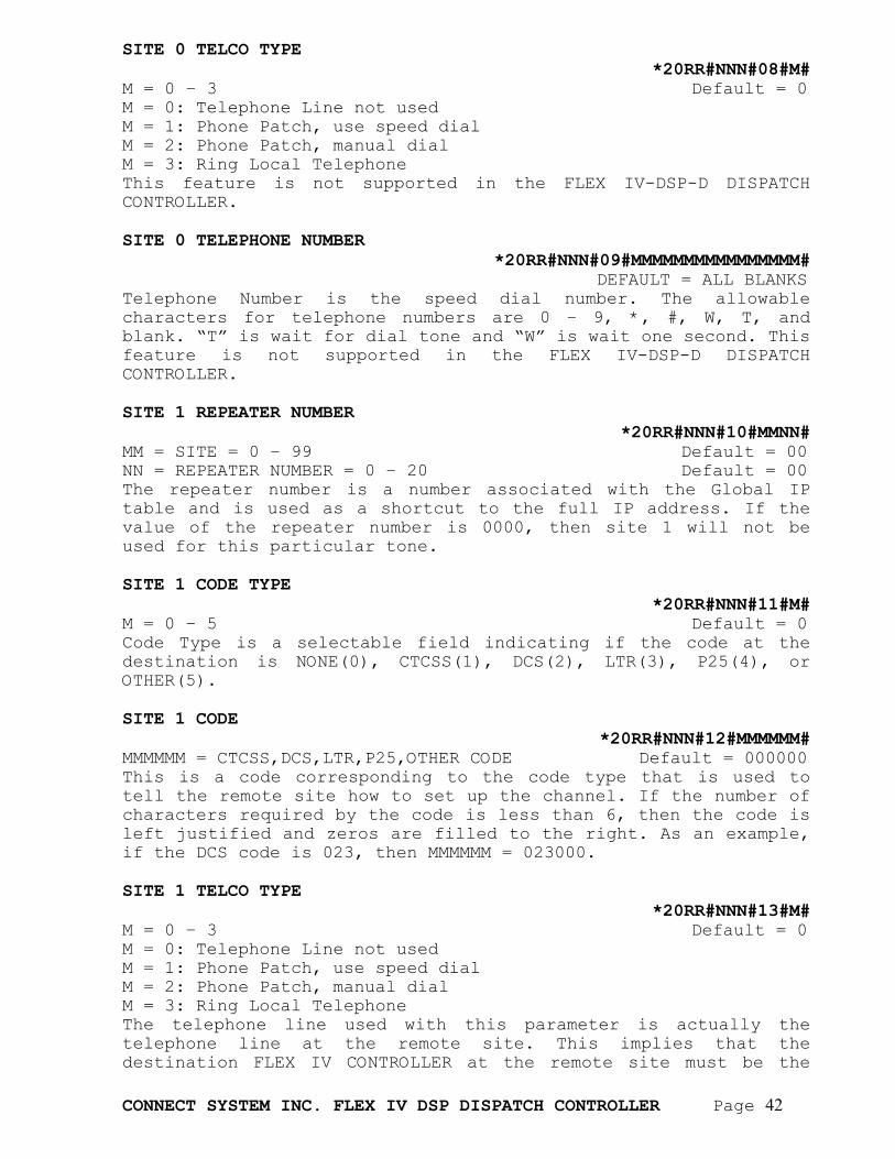
CONNECT SYSTEM INC. FLEX IV DSP DISPATCH CONTROLLER Page 42
SITE 0 TELCO TYPE *20RR#NNN#08#M#
M = 0 – 3 Default = 0 M = 0: Telephone Line not used M = 1: Phone Patch, use speed dial M = 2: Phone Patch, manual dial M = 3: Ring Local Telephone This feature is not supported in the FLEX IV-DSP-D DISPATCH CONTROLLER. SITE 0 TELEPHONE NUMBER
*20RR#NNN#09#MMMMMMMMMMMMMMMM# DEFAULT = ALL BLANKS Telephone Number is the speed dial number. The allowable characters for telephone numbers are 0 – 9, *, #, W, T, and blank. “T” is wait for dial tone and “W” is wait one second. This feature is not supported in the FLEX IV-DSP-D DISPATCH CONTROLLER. SITE 1 REPEATER NUMBER
*20RR#NNN#10#MMNN# MM = SITE = 0 – 99 Default = 00 NN = REPEATER NUMBER = 0 – 20 Default = 00 The repeater number is a number associated with the Global IP table and is used as a shortcut to the full IP address. If the value of the repeater number is 0000, then site 1 will not be used for this particular tone. SITE 1 CODE TYPE
*20RR#NNN#11#M# M = 0 – 5 Default = 0 Code Type is a selectable field indicating if the code at the destination is NONE(0), CTCSS(1), DCS(2), LTR(3), P25(4), or OTHER(5). SITE 1 CODE
*20RR#NNN#12#MMMMMM# MMMMMM = CTCSS,DCS,LTR,P25,OTHER CODE Default = 000000 This is a code corresponding to the code type that is used to tell the remote site how to set up the channel. If the number of characters required by the code is less than 6, then the code is left justified and zeros are filled to the right. As an example, if the DCS code is 023, then MMMMMM = 023000. SITE 1 TELCO TYPE
*20RR#NNN#13#M# M = 0 – 3 Default = 0 M = 0: Telephone Line not used M = 1: Phone Patch, use speed dial M = 2: Phone Patch, manual dial M = 3: Ring Local Telephone The telephone line used with this parameter is actually the telephone line at the remote site. This implies that the destination FLEX IV CONTROLLER at the remote site must be the
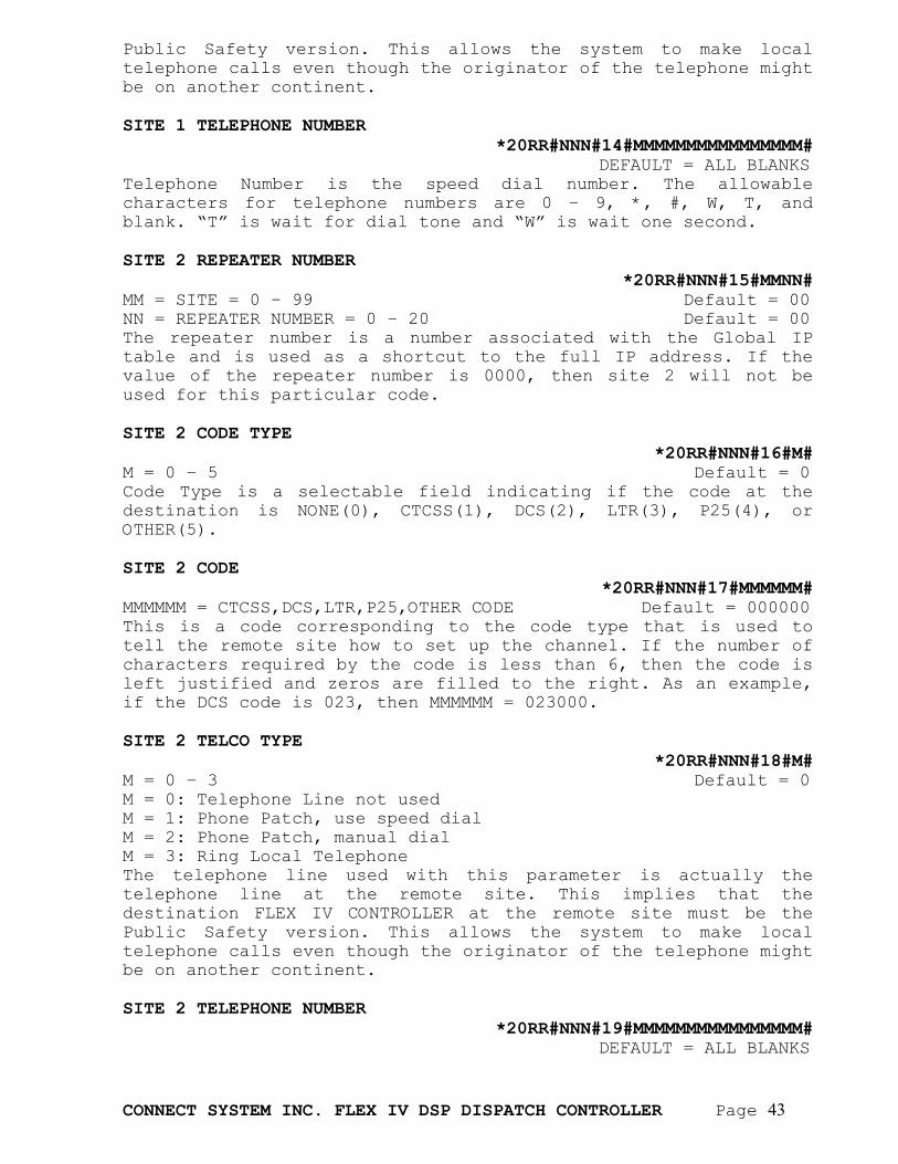
CONNECT SYSTEM INC. FLEX IV DSP DISPATCH CONTROLLER Page 43
Public Safety version. This allows the system to make local telephone calls even though the originator of the telephone might be on another continent. SITE 1 TELEPHONE NUMBER
*20RR#NNN#14#MMMMMMMMMMMMMMMM# DEFAULT = ALL BLANKS Telephone Number is the speed dial number. The allowable characters for telephone numbers are 0 – 9, *, #, W, T, and blank. “T” is wait for dial tone and “W” is wait one second. SITE 2 REPEATER NUMBER
*20RR#NNN#15#MMNN# MM = SITE = 0 – 99 Default = 00 NN = REPEATER NUMBER = 0 – 20 Default = 00 The repeater number is a number associated with the Global IP table and is used as a shortcut to the full IP address. If the value of the repeater number is 0000, then site 2 will not be used for this particular code. SITE 2 CODE TYPE
*20RR#NNN#16#M# M = 0 – 5 Default = 0 Code Type is a selectable field indicating if the code at the destination is NONE(0), CTCSS(1), DCS(2), LTR(3), P25(4), or OTHER(5). SITE 2 CODE
*20RR#NNN#17#MMMMMM# MMMMMM = CTCSS,DCS,LTR,P25,OTHER CODE Default = 000000 This is a code corresponding to the code type that is used to tell the remote site how to set up the channel. If the number of characters required by the code is less than 6, then the code is left justified and zeros are filled to the right. As an example, if the DCS code is 023, then MMMMMM = 023000. SITE 2 TELCO TYPE
*20RR#NNN#18#M# M = 0 – 3 Default = 0 M = 0: Telephone Line not used M = 1: Phone Patch, use speed dial M = 2: Phone Patch, manual dial M = 3: Ring Local Telephone The telephone line used with this parameter is actually the telephone line at the remote site. This implies that the destination FLEX IV CONTROLLER at the remote site must be the Public Safety version. This allows the system to make local telephone calls even though the originator of the telephone might be on another continent. SITE 2 TELEPHONE NUMBER
*20RR#NNN#19#MMMMMMMMMMMMMMMM# DEFAULT = ALL BLANKS
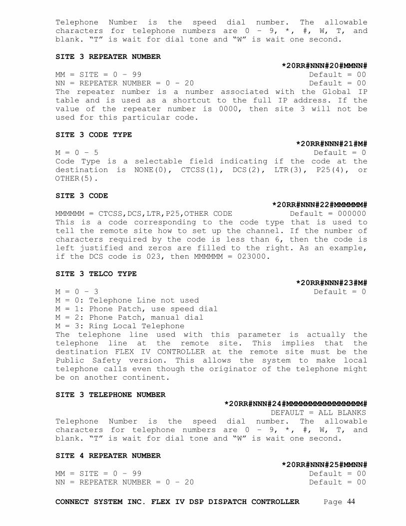
CONNECT SYSTEM INC. FLEX IV DSP DISPATCH CONTROLLER Page 44
Telephone Number is the speed dial number. The allowable characters for telephone numbers are 0 – 9, *, #, W, T, and blank. “T” is wait for dial tone and “W” is wait one second. SITE 3 REPEATER NUMBER
*20RR#NNN#20#MMNN# MM = SITE = 0 – 99 Default = 00 NN = REPEATER NUMBER = 0 – 20 Default = 00 The repeater number is a number associated with the Global IP table and is used as a shortcut to the full IP address. If the value of the repeater number is 0000, then site 3 will not be used for this particular code. SITE 3 CODE TYPE
*20RR#NNN#21#M# M = 0 – 5 Default = 0 Code Type is a selectable field indicating if the code at the destination is NONE(0), CTCSS(1), DCS(2), LTR(3), P25(4), or OTHER(5). SITE 3 CODE
*20RR#NNN#22#MMMMMM# MMMMMM = CTCSS,DCS,LTR,P25,OTHER CODE Default = 000000 This is a code corresponding to the code type that is used to tell the remote site how to set up the channel. If the number of characters required by the code is less than 6, then the code is left justified and zeros are filled to the right. As an example, if the DCS code is 023, then MMMMMM = 023000. SITE 3 TELCO TYPE
*20RR#NNN#23#M# M = 0 – 3 Default = 0 M = 0: Telephone Line not used M = 1: Phone Patch, use speed dial M = 2: Phone Patch, manual dial M = 3: Ring Local Telephone The telephone line used with this parameter is actually the telephone line at the remote site. This implies that the destination FLEX IV CONTROLLER at the remote site must be the Public Safety version. This allows the system to make local telephone calls even though the originator of the telephone might be on another continent. SITE 3 TELEPHONE NUMBER
*20RR#NNN#24#MMMMMMMMMMMMMMMM# DEFAULT = ALL BLANKS Telephone Number is the speed dial number. The allowable characters for telephone numbers are 0 – 9, *, #, W, T, and blank. “T” is wait for dial tone and “W” is wait one second. SITE 4 REPEATER NUMBER
*20RR#NNN#25#MMNN# MM = SITE = 0 – 99 Default = 00 NN = REPEATER NUMBER = 0 – 20 Default = 00
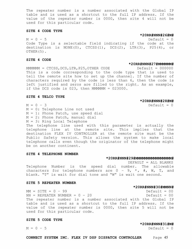
CONNECT SYSTEM INC. FLEX IV DSP DISPATCH CONTROLLER Page 45
The repeater number is a number associated with the Global IP table and is used as a shortcut to the full IP address. If the value of the repeater number is 0000, then site 4 will not be used for this particular code. SITE 4 CODE TYPE
*20RR#NNN#26#M# M = 0 – 5 Default = 0 Code Type is a selectable field indicating if the code at the destination is NONE(0), CTCSS(1), DCS(2), LTR(3), P25(4), or OTHER(5). SITE 4 CODE
*20RR#NNN#27#MMMMMM# MMMMMM = CTCSS,DCS,LTR,P25,OTHER CODE Default = 000000 This is a code corresponding to the code type that is used to tell the remote site how to set up the channel. If the number of characters required by the code is less than 6, then the code is left justified and zeros are filled to the right. As an example, if the DCS code is 023, then MMMMMM = 023000. SITE 4 TELCO TYPE
*20RR#NNN#28#M# M = 0 – 3 Default = 0 M = 0: Telephone Line not used M = 1: Phone Patch, use speed dial M = 2: Phone Patch, manual dial M = 3: Ring Local Telephone The telephone line used with this parameter is actually the telephone line at the remote site. This implies that the destination FLEX IV CONTROLLER at the remote site must be the Public Safety version. This allows the system to make local telephone calls even though the originator of the telephone might be on another continent. SITE 4 TELEPHONE NUMBER
*20RR#NNN#29#MMMMMMMMMMMMMMMM# DEFAULT = ALL BLANKS Telephone Number is the speed dial number. The allowable characters for telephone numbers are 0 – 9, *, #, W, T, and blank. “T” is wait for dial tone and “W” is wait one second. SITE 5 REPEATER NUMBER
*20RR#NNN#30#MMNN# MM = SITE = 0 – 99 Default = 00 NN = REPEATER NUMBER = 0 – 20 Default = 00 The repeater number is a number associated with the Global IP table and is used as a shortcut to the full IP address. If the value of the repeater number is 0000, then site 5 will not be used for this particular code. SITE 5 CODE TYPE
*20RR#NNN#31#M# M = 0 – 5 Default = 0

CONNECT SYSTEM INC. FLEX IV DSP DISPATCH CONTROLLER Page 46
Code Type is a selectable field indicating if the code at the destination is NONE(0), CTCSS(1), DCS(2), LTR(3), P25(4), or OTHER(5). SITE 5 CODE
*20RR#NNN#32#MMMMMM# MMMMMM = CTCSS,DCS,LTR,P25,OTHER CODE Default = 000000 This is a code corresponding to the code type that is used to tell the remote site how to set up the channel. If the number of characters required by the code is less than 6, then the code is left justified and zeros are filled to the right. As an example, if the DCS code is 023, then MMMMMM = 023000. SITE 5 TELCO TYPE
*20RR#NNN#33#M# M = 0 – 3 Default = 0 M = 0: Telephone Line not used M = 1: Phone Patch, use speed dial M = 2: Phone Patch, manual dial M = 3: Ring Local Telephone The telephone line used with this parameter is actually the telephone line at the remote site. This implies that the destination FLEX IV CONTROLLER at the remote site must be the Public Safety version. This allows the system to make local telephone calls even though the originator of the telephone might be on another continent. SITE 5 TELEPHONE NUMBER
*20RR#NNN#34#MMMMMMMMMMMMMMMM# DEFAULT = ALL BLANKS Telephone Number is the speed dial number. The allowable characters for telephone numbers are 0 – 9, *, #, W, T, and blank. “T” is wait for dial tone and “W” is wait one second. SITE 6 REPEATER NUMBER
*20RR#NNN#35#MMNN# MM = SITE = 0 – 99 Default = 00 NN = REPEATER NUMBER = 0 – 20 Default = 00 The repeater number is a number associated with the Global IP table and is used as a shortcut to the full IP address. If the value of the repeater number is 0000, then site 6 will not be used for this particular code. SITE 6 CODE TYPE
*20RR#NNN#36#M# M = 0 – 5 Default = 0 Code Type is a selectable field indicating if the code at the destination is NONE(0), CTCSS(1), DCS(2), LTR(3), P25(4), or OTHER(5). SITE 6 CODE
*20RR#NNN#37#MMMMMM# MMMMMM = CTCSS,DCS,LTR,P25,OTHER CODE Default = 000000
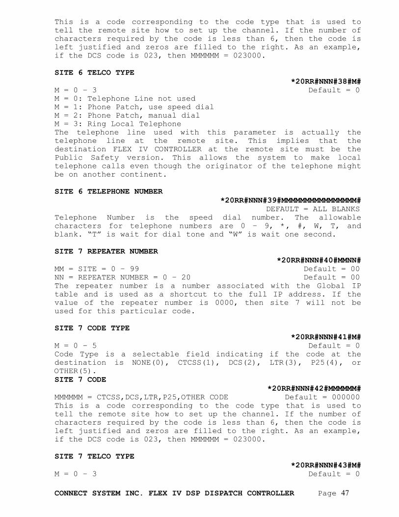
CONNECT SYSTEM INC. FLEX IV DSP DISPATCH CONTROLLER Page 47
This is a code corresponding to the code type that is used to tell the remote site how to set up the channel. If the number of characters required by the code is less than 6, then the code is left justified and zeros are filled to the right. As an example, if the DCS code is 023, then MMMMMM = 023000. SITE 6 TELCO TYPE
*20RR#NNN#38#M# M = 0 – 3 Default = 0 M = 0: Telephone Line not used M = 1: Phone Patch, use speed dial M = 2: Phone Patch, manual dial M = 3: Ring Local Telephone The telephone line used with this parameter is actually the telephone line at the remote site. This implies that the destination FLEX IV CONTROLLER at the remote site must be the Public Safety version. This allows the system to make local telephone calls even though the originator of the telephone might be on another continent. SITE 6 TELEPHONE NUMBER
*20RR#NNN#39#MMMMMMMMMMMMMMMM# DEFAULT = ALL BLANKS Telephone Number is the speed dial number. The allowable characters for telephone numbers are 0 – 9, *, #, W, T, and blank. “T” is wait for dial tone and “W” is wait one second. SITE 7 REPEATER NUMBER
*20RR#NNN#40#MMNN# MM = SITE = 0 – 99 Default = 00 NN = REPEATER NUMBER = 0 – 20 Default = 00 The repeater number is a number associated with the Global IP table and is used as a shortcut to the full IP address. If the value of the repeater number is 0000, then site 7 will not be used for this particular code. SITE 7 CODE TYPE
*20RR#NNN#41#M# M = 0 – 5 Default = 0 Code Type is a selectable field indicating if the code at the destination is NONE(0), CTCSS(1), DCS(2), LTR(3), P25(4), or OTHER(5). SITE 7 CODE
*20RR#NNN#42#MMMMMM# MMMMMM = CTCSS,DCS,LTR,P25,OTHER CODE Default = 000000 This is a code corresponding to the code type that is used to tell the remote site how to set up the channel. If the number of characters required by the code is less than 6, then the code is left justified and zeros are filled to the right. As an example, if the DCS code is 023, then MMMMMM = 023000. SITE 7 TELCO TYPE
*20RR#NNN#43#M# M = 0 – 3 Default = 0
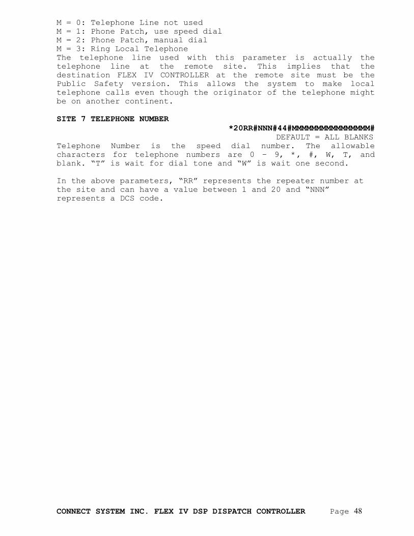
CONNECT SYSTEM INC. FLEX IV DSP DISPATCH CONTROLLER Page 48
M = 0: Telephone Line not used M = 1: Phone Patch, use speed dial M = 2: Phone Patch, manual dial M = 3: Ring Local Telephone The telephone line used with this parameter is actually the telephone line at the remote site. This implies that the destination FLEX IV CONTROLLER at the remote site must be the Public Safety version. This allows the system to make local telephone calls even though the originator of the telephone might be on another continent. SITE 7 TELEPHONE NUMBER
*20RR#NNN#44#MMMMMMMMMMMMMMMM# DEFAULT = ALL BLANKS Telephone Number is the speed dial number. The allowable characters for telephone numbers are 0 – 9, *, #, W, T, and blank. “T” is wait for dial tone and “W” is wait one second. In the above parameters, “RR” represents the repeater number at the site and can have a value between 1 and 20 and “NNN” represents a DCS code.
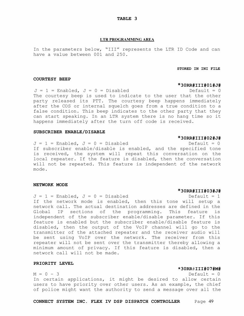
CONNECT SYSTEM INC. FLEX IV DSP DISPATCH CONTROLLER Page 49
TABLE 3
LTR PROGRAMMING AREA
In the parameters below, “III” represents the LTR ID Code and can have a value between 001 and 250. STORED IN INI FILE COURTESY BEEP
*30RR#III#01#J# J = 1 = Enabled, J = 0 = Disabled Default = 0 The courtesy beep is used to indicate to the user that the other party released its PTT. The courtesy beep happens immediately after the COS or internal squelch goes from a true condition to a false condition. This beep indicates to the other party that they can start speaking. In an LTR system there is no hang time so it happens immediately after the turn off code is received. SUBSCRIBER ENABLE/DISABLE
*30RR#III#02#J# J = 1 = Enabled, J = 0 = Disabled Default = 0 If subscriber enable/disable is enabled, and the specified tone is received, the system will repeat this conversation on the local repeater. If the feature is disabled, then the conversation will not be repeated. This feature is independent of the network mode. NETWORK MODE
*30RR#III#03#J# J = 1 = Enabled, J = 0 = Disabled Default = 1 If the network mode is enabled, then this tone will setup a network call. The actual destination addresses are defined in the Global IP sections of the programming. This feature is independent of the subscriber enable/disable parameter. If this feature is enabled but the subscriber enable/disable feature is disabled, then the output of the VoIP channel will go to the transmitter of the attached repeater and the receiver audio will be sent using VoIP over the network. The receiver from this repeater will not be sent over the transmitter thereby allowing a minimum amount of privacy. If this feature is disabled, then a network call will not be made. PRIORITY LEVEL
*30RR#III#07#M# M = 0 – 3 Default = 0 In certain applications, it might be desired to allow certain users to have priority over other users. As an example, the chief of police might want the authority to send a message over all the
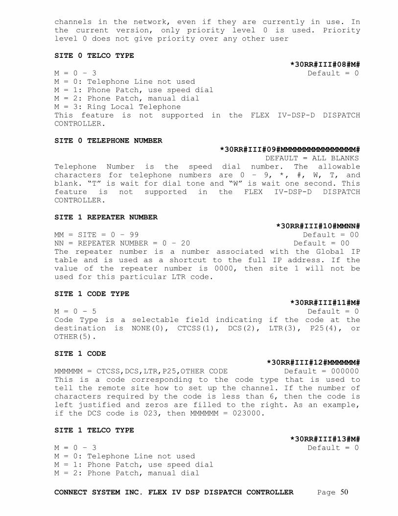
CONNECT SYSTEM INC. FLEX IV DSP DISPATCH CONTROLLER Page 50
channels in the network, even if they are currently in use. In the current version, only priority level 0 is used. Priority level 0 does not give priority over any other user SITE 0 TELCO TYPE
*30RR#III#08#M# M = 0 – 3 Default = 0 M = 0: Telephone Line not used M = 1: Phone Patch, use speed dial M = 2: Phone Patch, manual dial M = 3: Ring Local Telephone This feature is not supported in the FLEX IV-DSP-D DISPATCH CONTROLLER. SITE 0 TELEPHONE NUMBER
*30RR#III#09#MMMMMMMMMMMMMMMM# DEFAULT = ALL BLANKS Telephone Number is the speed dial number. The allowable characters for telephone numbers are 0 – 9, *, #, W, T, and blank. “T” is wait for dial tone and “W” is wait one second. This feature is not supported in the FLEX IV-DSP-D DISPATCH CONTROLLER. SITE 1 REPEATER NUMBER
*30RR#III#10#MMNN# MM = SITE = 0 – 99 Default = 00 NN = REPEATER NUMBER = 0 – 20 Default = 00 The repeater number is a number associated with the Global IP table and is used as a shortcut to the full IP address. If the value of the repeater number is 0000, then site 1 will not be used for this particular LTR code. SITE 1 CODE TYPE
*30RR#III#11#M# M = 0 – 5 Default = 0 Code Type is a selectable field indicating if the code at the destination is NONE(0), CTCSS(1), DCS(2), LTR(3), P25(4), or OTHER(5). SITE 1 CODE
*30RR#III#12#MMMMMM# MMMMMM = CTCSS,DCS,LTR,P25,OTHER CODE Default = 000000 This is a code corresponding to the code type that is used to tell the remote site how to set up the channel. If the number of characters required by the code is less than 6, then the code is left justified and zeros are filled to the right. As an example, if the DCS code is 023, then MMMMMM = 023000. SITE 1 TELCO TYPE
*30RR#III#13#M# M = 0 – 3 Default = 0 M = 0: Telephone Line not used M = 1: Phone Patch, use speed dial M = 2: Phone Patch, manual dial
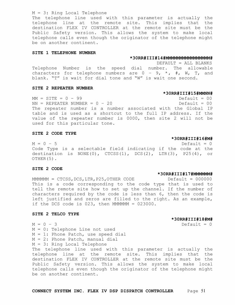
CONNECT SYSTEM INC. FLEX IV DSP DISPATCH CONTROLLER Page 51
M = 3: Ring Local Telephone The telephone line used with this parameter is actually the telephone line at the remote site. This implies that the destination FLEX IV CONTROLLER at the remote site must be the Public Safety version. This allows the system to make local telephone calls even though the originator of the telephone might be on another continent. SITE 1 TELEPHONE NUMBER
*30RR#III#14#MMMMMMMMMMMMMMMM# DEFAULT = ALL BLANKS Telephone Number is the speed dial number. The allowable characters for telephone numbers are 0 – 9, *, #, W, T, and blank. “T” is wait for dial tone and “W” is wait one second. SITE 2 REPEATER NUMBER
*30RR#III#15#MMNN# MM = SITE = 0 – 99 Default = 00 NN = REPEATER NUMBER = 0 – 20 Default = 00 The repeater number is a number associated with the Global IP table and is used as a shortcut to the full IP address. If the value of the repeater number is 0000, then site 2 will not be used for this particular tone. SITE 2 CODE TYPE
*30RR#III#16#M# M = 0 – 5 Default = 0 Code Type is a selectable field indicating if the code at the destination is NONE(0), CTCSS(1), DCS(2), LTR(3), P25(4), or OTHER(5). SITE 2 CODE
*30RR#III#17#MMMMMM# MMMMMM = CTCSS,DCS,LTR,P25,OTHER CODE Default = 000000 This is a code corresponding to the code type that is used to tell the remote site how to set up the channel. If the number of characters required by the code is less than 6, then the code is left justified and zeros are filled to the right. As an example, if the DCS code is 023, then MMMMMM = 023000. SITE 2 TELCO TYPE
*30RR#III#18#M# M = 0 – 3 Default = 0 M = 0: Telephone Line not used M = 1: Phone Patch, use speed dial M = 2: Phone Patch, manual dial M = 3: Ring Local Telephone The telephone line used with this parameter is actually the telephone line at the remote site. This implies that the destination FLEX IV CONTROLLER at the remote site must be the Public Safety version. This allows the system to make local telephone calls even though the originator of the telephone might be on another continent.
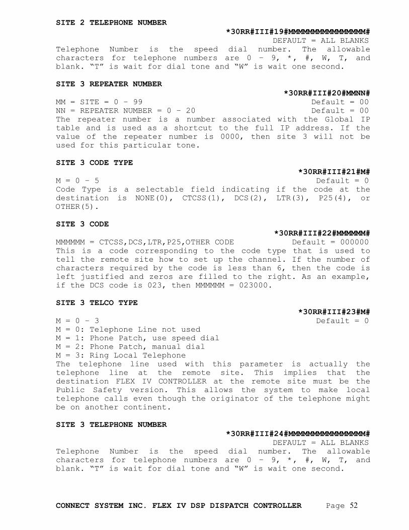
CONNECT SYSTEM INC. FLEX IV DSP DISPATCH CONTROLLER Page 52
SITE 2 TELEPHONE NUMBER *30RR#III#19#MMMMMMMMMMMMMMMM#
DEFAULT = ALL BLANKS Telephone Number is the speed dial number. The allowable characters for telephone numbers are 0 – 9, *, #, W, T, and blank. “T” is wait for dial tone and “W” is wait one second. SITE 3 REPEATER NUMBER
*30RR#III#20#MMNN# MM = SITE = 0 – 99 Default = 00 NN = REPEATER NUMBER = 0 – 20 Default = 00 The repeater number is a number associated with the Global IP table and is used as a shortcut to the full IP address. If the value of the repeater number is 0000, then site 3 will not be used for this particular tone. SITE 3 CODE TYPE
*30RR#III#21#M# M = 0 – 5 Default = 0 Code Type is a selectable field indicating if the code at the destination is NONE(0), CTCSS(1), DCS(2), LTR(3), P25(4), or OTHER(5). SITE 3 CODE
*30RR#III#22#MMMMMM# MMMMMM = CTCSS,DCS,LTR,P25,OTHER CODE Default = 000000 This is a code corresponding to the code type that is used to tell the remote site how to set up the channel. If the number of characters required by the code is less than 6, then the code is left justified and zeros are filled to the right. As an example, if the DCS code is 023, then MMMMMM = 023000. SITE 3 TELCO TYPE
*30RR#III#23#M# M = 0 – 3 Default = 0 M = 0: Telephone Line not used M = 1: Phone Patch, use speed dial M = 2: Phone Patch, manual dial M = 3: Ring Local Telephone The telephone line used with this parameter is actually the telephone line at the remote site. This implies that the destination FLEX IV CONTROLLER at the remote site must be the Public Safety version. This allows the system to make local telephone calls even though the originator of the telephone might be on another continent. SITE 3 TELEPHONE NUMBER
*30RR#III#24#MMMMMMMMMMMMMMMM# DEFAULT = ALL BLANKS Telephone Number is the speed dial number. The allowable characters for telephone numbers are 0 – 9, *, #, W, T, and blank. “T” is wait for dial tone and “W” is wait one second.
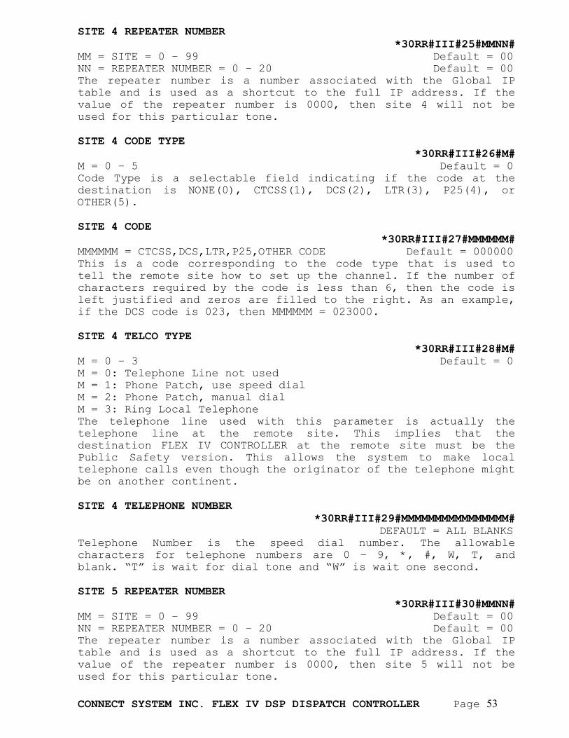
CONNECT SYSTEM INC. FLEX IV DSP DISPATCH CONTROLLER Page 53
SITE 4 REPEATER NUMBER *30RR#III#25#MMNN#
MM = SITE = 0 – 99 Default = 00 NN = REPEATER NUMBER = 0 – 20 Default = 00 The repeater number is a number associated with the Global IP table and is used as a shortcut to the full IP address. If the value of the repeater number is 0000, then site 4 will not be used for this particular tone. SITE 4 CODE TYPE
*30RR#III#26#M# M = 0 – 5 Default = 0 Code Type is a selectable field indicating if the code at the destination is NONE(0), CTCSS(1), DCS(2), LTR(3), P25(4), or OTHER(5). SITE 4 CODE
*30RR#III#27#MMMMMM# MMMMMM = CTCSS,DCS,LTR,P25,OTHER CODE Default = 000000 This is a code corresponding to the code type that is used to tell the remote site how to set up the channel. If the number of characters required by the code is less than 6, then the code is left justified and zeros are filled to the right. As an example, if the DCS code is 023, then MMMMMM = 023000. SITE 4 TELCO TYPE
*30RR#III#28#M# M = 0 – 3 Default = 0 M = 0: Telephone Line not used M = 1: Phone Patch, use speed dial M = 2: Phone Patch, manual dial M = 3: Ring Local Telephone The telephone line used with this parameter is actually the telephone line at the remote site. This implies that the destination FLEX IV CONTROLLER at the remote site must be the Public Safety version. This allows the system to make local telephone calls even though the originator of the telephone might be on another continent. SITE 4 TELEPHONE NUMBER
*30RR#III#29#MMMMMMMMMMMMMMMM# DEFAULT = ALL BLANKS Telephone Number is the speed dial number. The allowable characters for telephone numbers are 0 – 9, *, #, W, T, and blank. “T” is wait for dial tone and “W” is wait one second. SITE 5 REPEATER NUMBER
*30RR#III#30#MMNN# MM = SITE = 0 – 99 Default = 00 NN = REPEATER NUMBER = 0 – 20 Default = 00 The repeater number is a number associated with the Global IP table and is used as a shortcut to the full IP address. If the value of the repeater number is 0000, then site 5 will not be used for this particular tone.

CONNECT SYSTEM INC. FLEX IV DSP DISPATCH CONTROLLER Page 54
SITE 5 CODE TYPE
*30RR#III#31#M# M = 0 – 5 Default = 0 Code Type is a selectable field indicating if the code at the destination is NONE(0), CTCSS(1), DCS(2), LTR(3), P25(4), or OTHER(5). SITE 5 CODE
*30RR#III#32#MMMMMM# MMMMMM = CTCSS,DCS,LTR,P25,OTHER CODE Default = 000000 This is a code corresponding to the code type that is used to tell the remote site how to set up the channel. If the number of characters required by the code is less than 6, then the code is left justified and zeros are filled to the right. As an example, if the DCS code is 023, then MMMMMM = 023000. SITE 5 TELCO TYPE
*30RR#III#33#M# M = 0 – 3 Default = 0 M = 0: Telephone Line not used M = 1: Phone Patch, use speed dial M = 2: Phone Patch, manual dial M = 3: Ring Local Telephone The telephone line used with this parameter is actually the telephone line at the remote site. This implies that the destination FLEX IV CONTROLLER at the remote site must be the Public Safety version. This allows the system to make local telephone calls even though the originator of the telephone might be on another continent. SITE 5 TELEPHONE NUMBER
*30RR#III#34#MMMMMMMMMMMMMMMM# DEFAULT = ALL BLANKS Telephone Number is the speed dial number. The allowable characters for telephone numbers are 0 – 9, *, #, W, T, and blank. “T” is wait for dial tone and “W” is wait one second. SITE 6 REPEATER NUMBER
*30RR#III#35#MMNN# MM = SITE = 0 – 99 Default = 00 NN = REPEATER NUMBER = 0 – 20 Default = 00 The repeater number is a number associated with the Global IP table and is used as a shortcut to the full IP address. If the value of the repeater number is 0000, then site 6 will not be used for this particular tone. SITE 6 CODE TYPE
*30RR#III#36#M# M = 0 – 5 Default = 0 Code Type is a selectable field indicating if the code at the destination is NONE(0), CTCSS(1), DCS(2), LTR(3), P25(4), or OTHER(5).
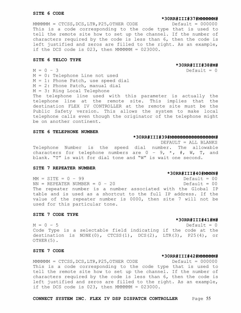
CONNECT SYSTEM INC. FLEX IV DSP DISPATCH CONTROLLER Page 55
SITE 6 CODE *30RR#III#37#MMMMMM#
MMMMMM = CTCSS,DCS,LTR,P25,OTHER CODE Default = 000000 This is a code corresponding to the code type that is used to tell the remote site how to set up the channel. If the number of characters required by the code is less than 6, then the code is left justified and zeros are filled to the right. As an example, if the DCS code is 023, then MMMMMM = 023000. SITE 6 TELCO TYPE
*30RR#III#38#M# M = 0 – 3 Default = 0 M = 0: Telephone Line not used M = 1: Phone Patch, use speed dial M = 2: Phone Patch, manual dial M = 3: Ring Local Telephone The telephone line used with this parameter is actually the telephone line at the remote site. This implies that the destination FLEX IV CONTROLLER at the remote site must be the Public Safety version. This allows the system to make local telephone calls even though the originator of the telephone might be on another continent. SITE 6 TELEPHONE NUMBER
*30RR#III#39#MMMMMMMMMMMMMMMM# DEFAULT = ALL BLANKS Telephone Number is the speed dial number. The allowable characters for telephone numbers are 0 – 9, *, #, W, T, and blank. “T” is wait for dial tone and “W” is wait one second. SITE 7 REPEATER NUMBER
*30RR#III#40#MMNN# MM = SITE = 0 – 99 Default = 00 NN = REPEATER NUMBER = 0 – 20 Default = 00 The repeater number is a number associated with the Global IP table and is used as a shortcut to the full IP address. If the value of the repeater number is 0000, then site 7 will not be used for this particular tone. SITE 7 CODE TYPE
*30RR#III#41#M# M = 0 – 5 Default = 0 Code Type is a selectable field indicating if the code at the destination is NONE(0), CTCSS(1), DCS(2), LTR(3), P25(4), or OTHER(5). SITE 7 CODE
*30RR#III#42#MMMMMM# MMMMMM = CTCSS,DCS,LTR,P25,OTHER CODE Default = 000000 This is a code corresponding to the code type that is used to tell the remote site how to set up the channel. If the number of characters required by the code is less than 6, then the code is left justified and zeros are filled to the right. As an example, if the DCS code is 023, then MMMMMM = 023000.
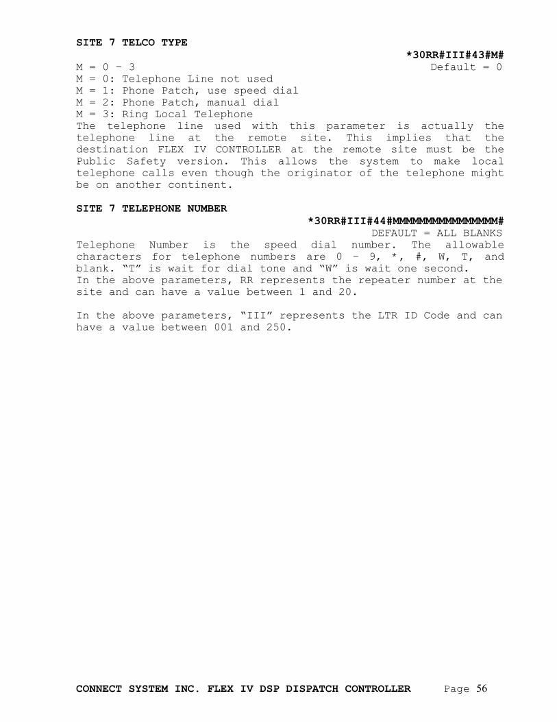
CONNECT SYSTEM INC. FLEX IV DSP DISPATCH CONTROLLER Page 56
SITE 7 TELCO TYPE
*30RR#III#43#M# M = 0 – 3 Default = 0 M = 0: Telephone Line not used M = 1: Phone Patch, use speed dial M = 2: Phone Patch, manual dial M = 3: Ring Local Telephone The telephone line used with this parameter is actually the telephone line at the remote site. This implies that the destination FLEX IV CONTROLLER at the remote site must be the Public Safety version. This allows the system to make local telephone calls even though the originator of the telephone might be on another continent. SITE 7 TELEPHONE NUMBER
*30RR#III#44#MMMMMMMMMMMMMMMM# DEFAULT = ALL BLANKS Telephone Number is the speed dial number. The allowable characters for telephone numbers are 0 – 9, *, #, W, T, and blank. “T” is wait for dial tone and “W” is wait one second. In the above parameters, RR represents the repeater number at the site and can have a value between 1 and 20. In the above parameters, “III” represents the LTR ID Code and can have a value between 001 and 250.
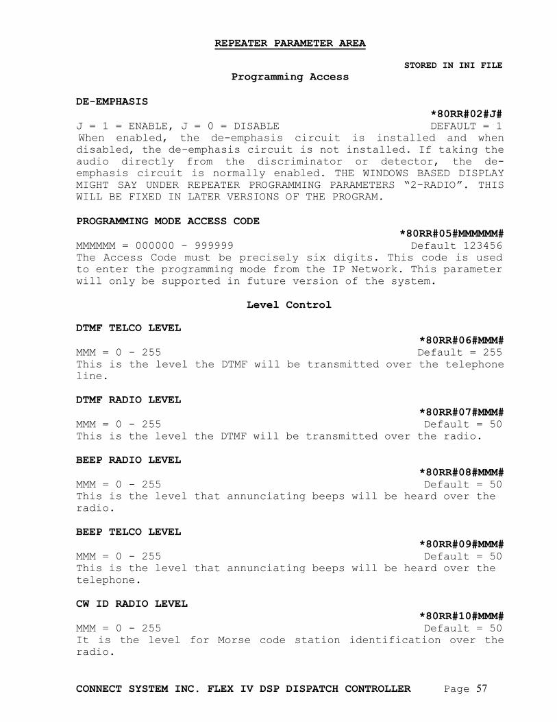
CONNECT SYSTEM INC. FLEX IV DSP DISPATCH CONTROLLER Page 57
REPEATER PARAMETER AREA
STORED IN INI FILE
Programming Access DE-EMPHASIS *80RR#02#J# J = 1 = ENABLE, J = 0 = DISABLE DEFAULT = 1 When enabled, the de-emphasis circuit is installed and when disabled, the de-emphasis circuit is not installed. If taking the audio directly from the discriminator or detector, the de-emphasis circuit is normally enabled. THE WINDOWS BASED DISPLAY MIGHT SAY UNDER REPEATER PROGRAMMING PARAMETERS “2-RADIO”. THIS WILL BE FIXED IN LATER VERSIONS OF THE PROGRAM. PROGRAMMING MODE ACCESS CODE
*80RR#05#MMMMMM# MMMMMM = 000000 - 999999 Default 123456 The Access Code must be precisely six digits. This code is used to enter the programming mode from the IP Network. This parameter will only be supported in future version of the system.
Level Control DTMF TELCO LEVEL
*80RR#06#MMM# MMM = 0 - 255 Default = 255 This is the level the DTMF will be transmitted over the telephone line. DTMF RADIO LEVEL
*80RR#07#MMM# MMM = 0 - 255 Default = 50 This is the level the DTMF will be transmitted over the radio. BEEP RADIO LEVEL
*80RR#08#MMM# MMM = 0 - 255 Default = 50 This is the level that annunciating beeps will be heard over the radio. BEEP TELCO LEVEL
*80RR#09#MMM# MMM = 0 - 255 Default = 50 This is the level that annunciating beeps will be heard over the telephone. CW ID RADIO LEVEL
*80RR#10#MMM# MMM = 0 - 255 Default = 50 It is the level for Morse code station identification over the radio.
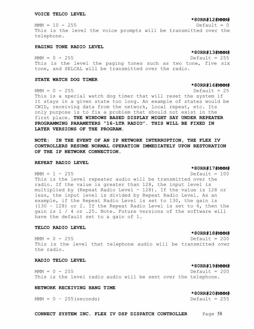
CONNECT SYSTEM INC. FLEX IV DSP DISPATCH CONTROLLER Page 58
VOICE TELCO LEVEL *80RR#12#MMM#
MMM = 10 - 255 Default = 0 This is the level the voice prompts will be transmitted over the telephone. PAGING TONE RADIO LEVEL
*80RR#13#MMM# MMM = 0 - 255 Default = 255 This is the level the paging tones such as two tone, five six tone, and SELCAL will be transmitted over the radio. STATE WATCH DOG TIMER
*80RR#16#MMM# MMM = 0 - 255 Default = 25 This is a special watch dog timer that will reset the system if it stays in a given state too long. An example of states would be CWID, receiving data from the network, local repeat, etc. Its only purpose is to fix a problem that should not exist in the first place. THE WINDOWS BASED DISPLAY MIGHT SAY UNDER REPEATER PROGRAMMING PARAMETERS “16-LTR RADIO”. THIS WILL BE FIXED IN LATER VERSIONS OF THE PROGRAM. NOTE: IN THE EVENT OF AN IP NETWORK INTERRUPTION, THE FLEX IV CONTROLLERS RESUME NORMAL OPERATION IMMEDIATELY UPON RESTORATION OF THE IP NETWORK CONNECTION. REPEAT RADIO LEVEL
*80RR#17#MMM# MMM = 1 - 255 Default = 100 This is the level repeater audio will be transmitted over the radio. If the value is greater than 128, the input level is multiplied by (Repeat Radio Level – 128). If the value is 128 or less, the input level is divided by Repeat Radio Level. As an example, if the Repeat Radio Level is set to 130, the gain is (130 – 128) or 2. If the Repeat Radio Level is set to 4, then the gain is 1 / 4 or .25. Note. Future versions of the software will have the default set to a gain of 1. TELCO RADIO LEVEL
*80RR#18#MMM# MMM = 0 - 255 Default = 200 This is the level that telephone audio will be transmitted over the radio. RADIO TELCO LEVEL
*80RR#19#MMM# MMM = 0 - 255 Default = 200 This is the level radio audio will be sent over the telephone. NETWORK RECEIVING HANG TIME
*80RR#20#MMM# MMM = 0 – 255(seconds) Default = 255
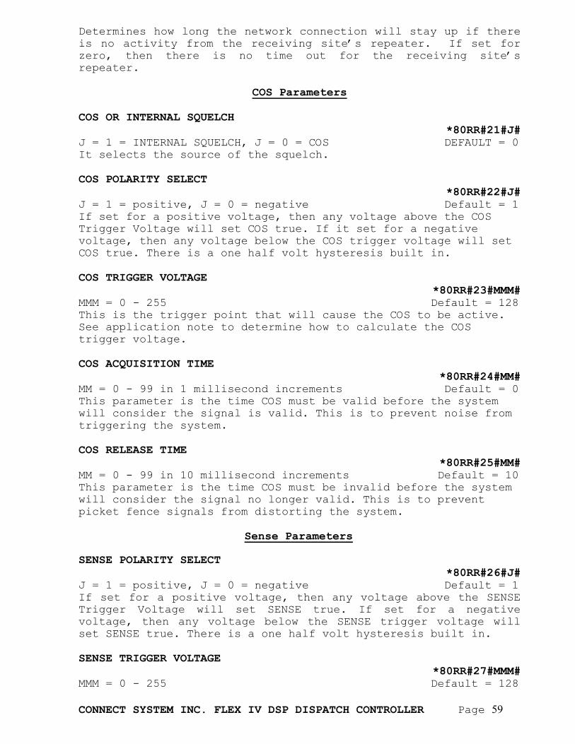
CONNECT SYSTEM INC. FLEX IV DSP DISPATCH CONTROLLER Page 59
Determines how long the network connection will stay up if there is no activity from the receiving site’s repeater. If set for zero, then there is no time out for the receiving site’s repeater.
COS Parameters COS OR INTERNAL SQUELCH
*80RR#21#J# J = 1 = INTERNAL SQUELCH, J = 0 = COS DEFAULT = 0 It selects the source of the squelch. COS POLARITY SELECT
*80RR#22#J# J = 1 = positive, J = 0 = negative Default = 1 If set for a positive voltage, then any voltage above the COS Trigger Voltage will set COS true. If it set for a negative voltage, then any voltage below the COS trigger voltage will set COS true. There is a one half volt hysteresis built in. COS TRIGGER VOLTAGE
*80RR#23#MMM# MMM = 0 - 255 Default = 128 This is the trigger point that will cause the COS to be active. See application note to determine how to calculate the COS trigger voltage. COS ACQUISITION TIME
*80RR#24#MM# MM = 0 - 99 in 1 millisecond increments Default = 0 This parameter is the time COS must be valid before the system will consider the signal is valid. This is to prevent noise from triggering the system. COS RELEASE TIME
*80RR#25#MM# MM = 0 - 99 in 10 millisecond increments Default = 10 This parameter is the time COS must be invalid before the system will consider the signal no longer valid. This is to prevent picket fence signals from distorting the system.
Sense Parameters SENSE POLARITY SELECT
*80RR#26#J# J = 1 = positive, J = 0 = negative Default = 1 If set for a positive voltage, then any voltage above the SENSE Trigger Voltage will set SENSE true. If set for a negative voltage, then any voltage below the SENSE trigger voltage will set SENSE true. There is a one half volt hysteresis built in. SENSE TRIGGER VOLTAGE
*80RR#27#MMM# MMM = 0 - 255 Default = 128
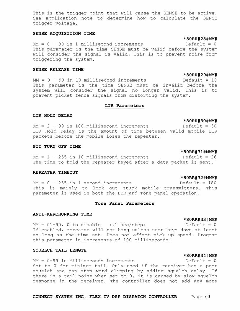
CONNECT SYSTEM INC. FLEX IV DSP DISPATCH CONTROLLER Page 60
This is the trigger point that will cause the SENSE to be active. See application note to determine how to calculate the SENSE trigger voltage. SENSE ACQUISITION TIME
*80RR#28#MM# MM = 0 - 99 in 1 millisecond increments Default = 0 This parameter is the time SENSE must be valid before the system will consider the signal is valid. This is to prevent noise from triggering the system. SENSE RELEASE TIME
*80RR#29#MM# MM = 0 - 99 in 10 millisecond increments Default = 10 This parameter is the time SENSE must be invalid before the system will consider the signal no longer valid. This is to prevent picket fence signals from distorting the system.
LTR Parameters LTR HOLD DELAY
*80RR#30#MM# MM = 2 – 99 in 100 millisecond increments Default = 30 LTR Hold Delay is the amount of time between valid mobile LTR packets before the mobile loses the repeater. PTT TURN OFF TIME
*80RR#31#MMM# MM = 1 – 255 in 10 millisecond increments Default = 26 The time to hold the repeater keyed after a data packet is sent. REPEATER TIMEOUT
*80RR#32#MMM# MM = 0 - 255 in 1 second increments Default = 180 This is mainly to lock out stuck mobile transmitters. This parameter is used in both the LTR and Tone panel operation.
Tone Panel Parameters ANTI-KERCHUNKING TIME
*80RR#33#MM# MM = 01-99, 0 to disable (.1 sec/step) Default = 0 If enabled, repeater will not hang unless user keys down at least as long as the time set. Does not affect pick up speed. Program this parameter in increments of 100 milliseconds. SQUELCH TAIL LENGTH
*80RR#34#MM# MM = 0-99 in Milliseconds increments Default = 0 Set to 0 for minimum tail. Only used if the receiver has a poor squelch and can stop word clipping by adding squelch delay. If there is a tail noise when set to 0, it is caused by slow squelch response in the receiver. The controller does not add any more
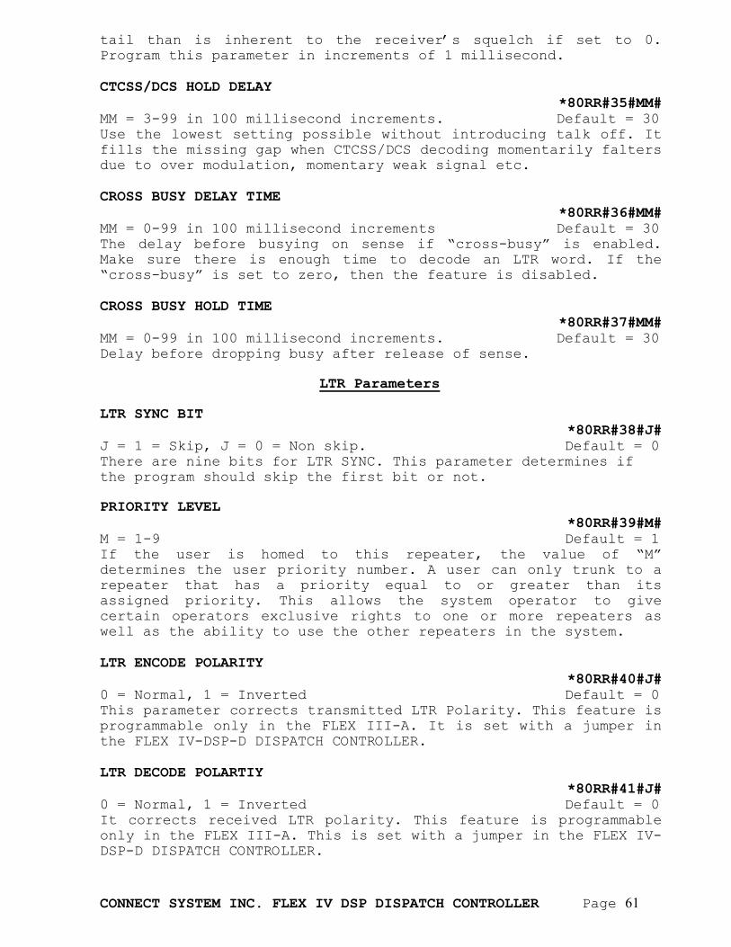
CONNECT SYSTEM INC. FLEX IV DSP DISPATCH CONTROLLER Page 61
tail than is inherent to the receiver’s squelch if set to 0. Program this parameter in increments of 1 millisecond. CTCSS/DCS HOLD DELAY
*80RR#35#MM# MM = 3-99 in 100 millisecond increments. Default = 30 Use the lowest setting possible without introducing talk off. It fills the missing gap when CTCSS/DCS decoding momentarily falters due to over modulation, momentary weak signal etc. CROSS BUSY DELAY TIME
*80RR#36#MM# MM = 0-99 in 100 millisecond increments Default = 30 The delay before busying on sense if “cross-busy” is enabled. Make sure there is enough time to decode an LTR word. If the “cross-busy” is set to zero, then the feature is disabled. CROSS BUSY HOLD TIME
*80RR#37#MM# MM = 0-99 in 100 millisecond increments. Default = 30 Delay before dropping busy after release of sense.
LTR Parameters LTR SYNC BIT
*80RR#38#J# J = 1 = Skip, J = 0 = Non skip. Default = 0 There are nine bits for LTR SYNC. This parameter determines if the program should skip the first bit or not. PRIORITY LEVEL
*80RR#39#M# M = 1-9 Default = 1 If the user is homed to this repeater, the value of “M” determines the user priority number. A user can only trunk to a repeater that has a priority equal to or greater than its assigned priority. This allows the system operator to give certain operators exclusive rights to one or more repeaters as well as the ability to use the other repeaters in the system. LTR ENCODE POLARITY
*80RR#40#J# 0 = Normal, 1 = Inverted Default = 0 This parameter corrects transmitted LTR Polarity. This feature is programmable only in the FLEX III-A. It is set with a jumper in the FLEX IV-DSP-D DISPATCH CONTROLLER. LTR DECODE POLARTIY
*80RR#41#J# 0 = Normal, 1 = Inverted Default = 0 It corrects received LTR polarity. This feature is programmable only in the FLEX III-A. This is set with a jumper in the FLEX IV-DSP-D DISPATCH CONTROLLER.
CONNECT SYSTEM INC. FLEX IV DSP DISPATCH CONTROLLER Page 62
TEST ID CODE
*80RR#42#MMM# MMM = 001 - 250 Default = 002 This ID code with the home repeater equal to this repeater number will be transmitted continuously to allow alignment of the transmitter. IDLE MESSAGE TIMER
*80RR#43#MMM# MMM = 0 – 255 (1 – 255 Seconds) Default = 10 Sets the time interval that the idle message will be sent. If set to zero, the idle message will not be sent. Certain radios may need the idle message to work properly. This parameter is in 1 second increments. AREA BIT
*80RR#44#J# J = 0 = Area 0, J = 1 = Area 1 Default = 0 It determines the area for this repeater. MASTER OR SLAVE
*80RR#45#J# J = 0 = Master, J = 1 = Slave. Default = 1 There can be only one master in the system. The master should be the first physical repeater in the daisy chain and the last and only the last repeater in the daisy chain should have its terminating resistor on the RS485 bus.
CTCSS/DCS Parameters DCS ENCODE POLARITY
*80RR#46#J# J = 0 = Normal, J = 1 = Inverted Default = 0 It corrects transmitted DCS Polarity. This feature is programmable only in the FLEX III-A. This is set using a jumper in the FLEX IV-DSP-D DISPATCH CONTROLLER. DCS DECODE POLARTIY
*80RR#47#J# J = 0 = Normal, J = 1 = Inverted Default = 0 It corrects received DCS polarity. This feature is programmable only in the FLEX III-A. This is set using a jumper in the FLEX IV-D DSP DISPATCH CONTROLLER. COURTESY TONE DELAY
*80RR#48#MM# MM = 0- 99 (.01-.99 Seconds) Default = 10 Delays courtesy beep after the mobile drops its carrier. Program this parameter in increments of 10 milliseconds.
CONNECT SYSTEM INC. FLEX IV DSP DISPATCH CONTROLLER Page 63
SUBSCRIBER HANG TIME *80RR#49#MM#
MM = 0 - 99 (0-9.9 Seconds) Default = 30 Determines how long the carrier remains on after the CTCSS/DCS drops. Program this parameter in increments of 100 milliseconds. CARRIER DROP DELAY
*80RR#50#MM# MM = 00-99, (0 - .99 Seconds) Default = 99 Adjusts how long carrier remains on after CTCSS/DCS drops at end of hang time. Keeping the carrier on quiets the mobile while the mobile CTCSS/DCS decoder is dropping and allows the repeater to go off without a squelch tail heard. The default value is .99 seconds and probably will not need to be changed. Program this parameter in increments of 10 milliseconds Note: The carrier drop delay is additive to hang time and in effect increases the total beyond the value set for hang time.
Common Repeater Parameters ACCESS DELAY
*80RR#51#MM# MM = 0-99, (0-9.9 Seconds) Default = 10 It is user selectable to add delays to compensate for PTT hang after pressing a DTMF key on mobile OR portable radios. Select a value that allows you to hear all of the return DTMF in programming mode without clipping. Program this parameter in increments of 100 milliseconds. STATION IDENTIFICATION MODE
*80RR#52#J# J = 0 = BEACON, J = 1 = Activity Default = 0 In Beacon mode, the Station ID will go out periodically according to the interval. In Activity mode, the Station ID will go out periodically according to the interval but only if there was activity since the last transmission. REPEATER CW ID INTERVAL
*80RR#54#MM# MM = 01-99, 0 to disable (1-99 Minutes) Default = 0 Determines how often the system will send its call sign using voice or Morse code when the system is not in use. Program this parameter in increments of 1 minute. Zero means disabled. CW ID SPEED
*80RR#55#MM# MM = 04-99 (10 Milliseconds for a DI) Default = 5 (20 WPM) Determines how fast the Morse code will be sent. The larger the number, the slower the speed is. A DAH is three times longer than a DI.
CONNECT SYSTEM INC. FLEX IV DSP DISPATCH CONTROLLER Page 64
CWID FREQUENCY *80RR#56#MM#
MM = 1 – 20 Default = 5 It sets the frequency of the Morse code per the user’s preference. By having a different frequency for each repeater, the user can determine which repeater is active if they are being monitored. When “N” = 1, then the frequency is 400 Hz. Each increment of “N” increases the frequency by 100 Hz. CWID SEQUENCE CHARACTERS
*80RR#57#MMMMMMMMMM# MMMMMMMMMM Default blank The station call sign can consist of any letter, number, and a few special characters that can be up to 10 characters in length. Trailing blanks are ignored and any illegal character will be sent. Lower case and upper case letters can be used. PTT TURN DELAY
*80RR#58#MM# MM = 0 = 99 (0 - .99 Seconds) Default = 10 It’s the time to wait after keying the repeater before issuing an LTR or DCS code. This delay compensates for any key-up delay in the transmitter. Program this parameter in increments of 10 milliseconds. COURTESY BEEP FREQUENCY
*80RR#59#MM# MM = 1 – 20 Default = 5 It sets the frequency of the courtesy beep per the user’s preference. By having a different frequency for each repeater, the user can determine which repeater is active if they are being monitored. When “N” = 1, then the frequency is 400 Hz. Each increment of “N” increases the frequency by 100 Hz. REPEATER DISABLE
*80RR#60#M# M = 0 -2 Default = 0 It allows the repeater to be in special modes in case of trouble with co-channel users or other things. 0 = Normal operation 1 = Shut down like the repeater does not even exist 2 = Will transmit GOTO information on its channel but will not act as a repeater. AUX RELAY
*80RR#61#J# J = 0 = Not used, J = 1 = follows PTT Default = 0 It allows the aux relay to be used in place of PTT. It’s useful for positive keying, or the current needed exceeds the capacity of the PTT transistor, or the PTT transistor gets fried. CROSS BUSY MODE
*80RR#62#M# M = 0 - 4 Default = 0
CONNECT SYSTEM INC. FLEX IV DSP DISPATCH CONTROLLER Page 65
If N = 0, Cross Busy is not used for this repeater. The system can process LTR, CTCSS and DCS codes. If N = 1, the system monitors the Carrier. If Carrier is active and there is no LTR code found, the system will be in Cross Busy mode 1 and it will not become active. If N = 2, the system monitors the Carrier. If Carrier is active and there is no LTR code found, the system will be in Cross Busy mode 2, and send out GOTO message using the test ID code. If N = 3, the system looks at the Sense input. If the Sense input is active, the system will be in Cross Busy mode 3 and it will not activate. If N = 4, the system looks at the Sense input. If the sense input is active, the system will be in Cross Busy mode 4 and keep sending out GOTO message using the test ID code. For all cross busy modes except 0, only LTR will be processed. RADIO REPEATER GAIN
*80RR#63#M# M = 1 - 9 Default = 1 It acts as an electronic pre-amp for the audio coming from the radio. Effectively increases the repeater gain. TELCO REPEATER GAIN
*80RR#64#M# M = 1 - 9 Default = 1 It acts as an electronic pre-amp for the audio coming from the telephone jack.
Networking Parameters
NETWORK HANG TIME
*80RR#65#MM# MM = 00 - 99 (0 – 99 Seconds) Default = 20 Determines how long the network connection will stay up if there is no activity from either the local repeater or the remote repeater. The network hang time must be set the same at each site. If set for zero, then it’s for dispatch mode.
Miscellaneous Parameters NETWORK ACTIVITY TIME
*80RR#71#MMM# MMM = 0 – 255 (0 = Disable) Default = 0 This parameter is used to free up the repeater at a given site if during a network call the intended party does not answer within a specified time. Lets assume that a network call goes out on five separate repeater sites. If the person to whom the call is intended answers, then the repeater will remain active for the duration of the call while the other repeater sites will disconnect from the network call and be available for local dispatch. If more than one site responds within the specified time, then the additional sites will remain active for the
CONNECT SYSTEM INC. FLEX IV DSP DISPATCH CONTROLLER Page 66
duration of the call. If the value of this parameter is set to zero, then all sites specified for this call will be active for the duration of the call. REPEATER INDEX
*80RR#72#MM# MM = 0 – 63 DEFAULT = 0 Reserved for future use REPEATER TYPE
*80RR#73#M# M = 0 – 6 DEFAULT = 0 Repeater type defines the configuration of the system. The following defines each of the following types:
1. Conventional: If this repeater type is selected, then the FLEX IV-DSP-D DISPATCH CONTROLLER will be set up to receive and transmit CTCSS, DCS, and LTR type of formats.
2. Console: If this repeater type is selected, then the FLEX IV-DSP-P PUBLIC SAFETY CONTROLLER will be connected and controlled from the console via the four wire balanced audio port.
3. REMOTE: If this repeater type is selected, then the FLEX IV-DSP-D DISPATCH CONTROLLER will work with a repeater that is controlled by the EIA tones.
4. P25: 5. Type 1: 6. Type 2:
CONNECT SYSTEM INC. FLEX IV DSP DISPATCH CONTROLLER Page 67
IP LOCAL AREA
STORED IN INI FILE PRIMARY SUBNET MASK
*60RR#01#MMMMMMMMMMMM# MMM.MMM.MMM.MMM, MMM = 000 - 255 Default = 000000000000 Depending on the network that has been designed, it is possible to have certain controllers on the local area network and some controllers accessible through a gateway and available on the wide area network. The network mask determines which IP addresses are on the local area network and which IP addresses are on the wide area network. PRIMARY GATEWAY
*60RR#02#MMMMMMMMMMMM# MMM.MMM.MMM.MMM, MMM = 000 - 255 Default = 000000000000 If the controllers you are trying to communicate with are not on the local area network, then the system has to send the IP packets through a gateway to reach the wide area network. This is the IP address of the gateway. PRIMARY MAC ADDRESS
*60RR##03#MMMMMMMMMMMM# MMMMMMMMMMMM = 000000000000–FFFFFFFFFFFF(HEX) Default = 000000000 To reach a controller over a local area network it is necessary for each device connected to the network to have a unique address. This unique address is called the MAC (Media Access Controller) address and is stored and used in the Ethernet Controller Integrated Circuit. SECONDARY IP ADDRESS
*60RR#04#MMMMMMMMMMMM# MMM.MMM.MMM.MMM, MMM = 000 - 255 Default = 000000000000 This feature is only supported in the public safety version of the controller. This will only be the device to have two separate IP addresses if you have two separate IP networks. SECONDARY SUBNET MASK
*60RR#05#MMMMMMMMMMMM# MMM.MMM.MMM.MMM, MMM = 000 - 255 Default = 000000000000 This mask determines which IP addresses belong to the local area network and which IP addresses belong to the wide area network for the secondary IP network. SECONDARY GATEWAY
*60RR#06#MMMMMMMMMMMM# MMM.MMM.MMM.MMM, MMM = 000 - 255 Default = 000000000000 This feature is only supported in the public safety version of the controller. This is the IP address for the gateway on the secondary IP network and is only used if the controller you are trying to communicate with is not on the local area network.
CONNECT SYSTEM INC. FLEX IV DSP DISPATCH CONTROLLER Page 68
SECONDARY MAC ADDRESS *60RR##07#MMMMMMMMMMMM#
MMMMMMMMMMMM = 000000000000–FFFFFFFFFFFF(HEX) Default = 000000000 The public safety version of the controller has a duplicate Ethernet Controller. This feature will be used in some versions of the product to allow redundant IP networks. Depending on the system, the MAC address may or may not be the same as the primary MAC address.
CONNECT SYSTEM INC. FLEX IV DSP DISPATCH CONTROLLER Page 69
IP REMOTE AREA STORED IN INI FILE IP ADRESS
*70SS#RR#01#MMMMMMMMMMMM# MMM.MMM.MMM.MMM, MMM = 000 - 255 Default = 000000000000 Each repeater at each site has an IP address. All FLEX IV DSP controllers must be assigned a Static IP address, then the number represents the IP address assigned to the repeater. IP DTMF CODE
*70SS#RR#02#MMMM# RESERVED FOR OTHER SPECIAL APPLICATION IP MODE
*70SS#RR#03#M# RESERVED FOR FUTURE USE IP INDEX
*70SS#RR#04#MM# RESERVED FOR FUTURE USE
CONNECT SYSTEM INC. FLEX IV DSP DISPATCH CONTROLLER Page 70
FCC NOTICE TO USERS 1. This device complies with part 15 of the FCC rules.
Operation is subject to the following two conditions: (1) This device may not cause harmful interference, and (2) This device must accept any interference received, including interference which may cause undesirable operation.
2. This equipment generates and uses radio frequency energy and
if not installed and used properly, i.e. in strict accordance with the service manual, may cause interference to radio or television reception. It has been tested and found to comply with the limits for a Class B computing device pursuant to Subpart J of Part 15 of FCC rules, which are designed to provide reasonable protection against such interference when operated in a residential installation.
3. If this equipment does cause interference to radio or
television reception, which can be determined by turning the equipment off and on, the user is encouraged to try to correct the interference by one or more of the following measures:
a. Reorient the receiving antenna. b. Relocate the equipment with respect to the receiver. c. Move the equipment away from the receiver. d. Plug the equipment into a different outlet so that
equipment and receiver are on different branch circuits.
e. Ensure that card mounting screws, attachment connector
screws, and ground wires are tightly secured. f. If cables not offered by this company are used with
this equipment, it is suggested that you use shielded, grounded cables with in line filters, if necessary.
g. If necessary consult your service representative for
additional suggestions. 4. The manufacturer is not responsible for any radio or TV
interference caused by unauthorized modifications to this equipment. It is the responsibility of the user to correct such interference.
CONNECT SYSTEM INC. FLEX IV DSP DISPATCH CONTROLLER Page 71
REVISION HISTORY July 20, 2006 (Version 1.00) First production Release Sept 11, 2006 (Version 1.01) Corrected minor typos. Deleted installation procedures and diagnostic modes until next version of manual December 8, 2006 (Version 1.02) Made the following changes: 1. Repeater Parameter number 20 changed to NETWORK RECEIVING HANG TIME. 2. Repeater Parameter number 43 called Idle message timer changed from increments of 10 seconds to 1 second 3.Repeater Parameter number 17 called Repeat Radio Level redefined 4. CWID speed changed from 1 millisecond per increment to 10 millisecond per increment for a di. Version 005 of the software has the following major revisions. 1. The microprocessor does not sometimes erase itself when the power is cycled. 2. CWID is implemented 3. The local repeat function delay is changed from about 1 second to about 160 milliseconds 4. Repeater gain is implemented. This will allow the Discriminator input voltage to work from about 50 millivolts to about 3 volts with a repeater output of 100 millivolts to about 3 volts. 5. If network call and if LTR repeater is busy, the network will find an available non busy LTR repeater. Version 006 of the software has the following major revisions. 1. For local repeaters, the voice delay is reduced from 40 milliseconds to 125 microseconds 2. The DCS level is changed from 33 percent of the LTR level to 80% of LTR level. Version 007 of the software has the following major revisions. 1. The time for programming the parameters is reduced from 6 minutes to 1 minute. 2. Changed the LTR decode algorithm to make it more reliable. 3. Fixed a problem where the DCS did not cause the remote sites to turn off. Version 008A of the software has the following enhancements and fixes. 1. Added a function where an external program can be used to monitor the status of the network and the units in your system. 2. Fixed a problem that prevented remote programming of the unit while someone was talking. 3. Added a programmable de-emphasis function to the unit. This change will significantly increase the voice quality if the voice seems tinny.
CONNECT SYSTEM INC. FLEX IV DSP DISPATCH CONTROLLER Page 72
4. Added a watchdog timer to restart the system if the unit was not initialized properly. 5. Added a watchdog timer to restart the system if the communications between the microprocessor and the DSP fails. Version 008B of the software has the following enhancements and fixes: 1. If the system stays in an active state more than a user specified time, the system will restart the system. This “user specified time” is 10 second increments between 10 and 2550 seconds. This is parameter 16 in the repeater section. 2. Changed the logic in the communication between the microprocessor and the DSP so the information will be resent if not received the first time.